

Page 1
Page 2

CONTENTS
1. Description of Machine
2. Sewiight
3. Installing Head into Cabinet
4. Threading the Machine & Needle
5. Threading the Bobbin Case ................................................. 5
........................................................................................................
........................................... ?
............................................................
.......
......................... ..............
” 3
...............
3
4
6. Inserting and Removing the Bobbin Case ......................’T” 6
7. Cleaning the Shuttle Race
8. Preparing for Sewing
9. Starting Sewing
10. Setting the Needle
11. Pushbutt jn Drop Feed (Feed Dog Position Regulator)
12. Regulating the Thread Tension
13. Pushbutton Darner (Presser Foot Pressure Reguiator) .,.’rr 11
14. Winding the Bobbin................................................................................
15. Regulating the Stitch Length for Forward Sewing.
16. Regulating the Stitch Length for Reverse Sewing
I!- Regulating the Stitch Length for Zig-Zag Sewing
18. Regulating Width of Zig-Zag Stitch
19. Regulating Length of Zig-Zag Stitch
20. Inserting the Disc
21-22. Sewing Design
¿0, Oiling...................
24. Button Sewing
25. Making Buttonholes..
26. Darning, Embroidering & Monogramming................. , 2I
27. Narrow Hemmer
28. Sewing Braids............................................................................................ oa
29. Felling........................................
30. Cloth Guide................................................................................................. 24
31. Quilting.......................................................................................................... 24
32. Causes of Common Difficulties
33. Needle & Thread Size
..........................................................
....
.......................................
.
.......................................
............................................’......
....
.............................................................................
...........................................................
........................................
.......
..............................
..................... . . * '
....................................................................................
.................................................................................... 22
......................................................................
..................................................................
...................................................................................
' 9
........................................................ jq
................! ..
....................................................... 14
.ZZ’''.'.','.’.'.'.'' 16.'' 17
......
....... 18
........................................... 19
........................
'.
...............................
..............................
...................................
' ’ ‘ 14
..................
..............'13
...
...............
7
g
g
9
‘‘‘] 12
13
13
«
20
25
26
Page 3

MacJtme.
1 2 3 4 5 6
40
39
10 29 28 27^6
1-2 Pushbutton darner
3 Thread take up lever
4 Upper arm thread guide
5 Arm cover
6 Automatic stitch cam puli lid
7 Zigzag width indicator
9 10 11
8 Spool pin
9 Zigzag width dial
10-11 Zigzag width stoppers
12 Bobbin winder release lever
13 Bobbin winder shaft
14 Bobbin winder push plate
15 Bobbin winder rubber wheel
16 Balance wheel (hand wheel)
17 Pushbutton stitch reverse
18 Stitch length indicator
19 Stitch length dial
20 Vertical arm
21 Sewlight switch knob
22 Bobbin winder thread guide
23-24 Pushbutton drop feed
25 Bed-plate
26 Vertical arm ,
27 Needle clamp screw
28 Needle clamp
29 Needle
30 Needle plate
31 Feed dog
32 Slide plate
33 Hinged presser foot
34 Presser foot thumb screw
35 Presser bar
36-37 Face plate thread guides
38 Thread retainer bar
39 Calibrated thread tension dial
40 Thread take-up spring
Page 4
Beudlfiii
I'he lamp housing is located at the front side
of the arm under the arm cover (Fig. 2).
The light switch knob is located at the riglit
side of the vertical arm. To switch on the
light turn the light-switch knob clockwise or
counter-clockwise. To switch off the light
turn the light-switch knob clockwise or
counter-clockwise. In order to replace a
burnt out bulb with a new one, loosen the
two screws on the top of the arm-cover and
remove the cover. Bulbs (15w) may be
obtained at dealers, department stores and
electricals stores.
Sewlight Switch knob
Fig. 2
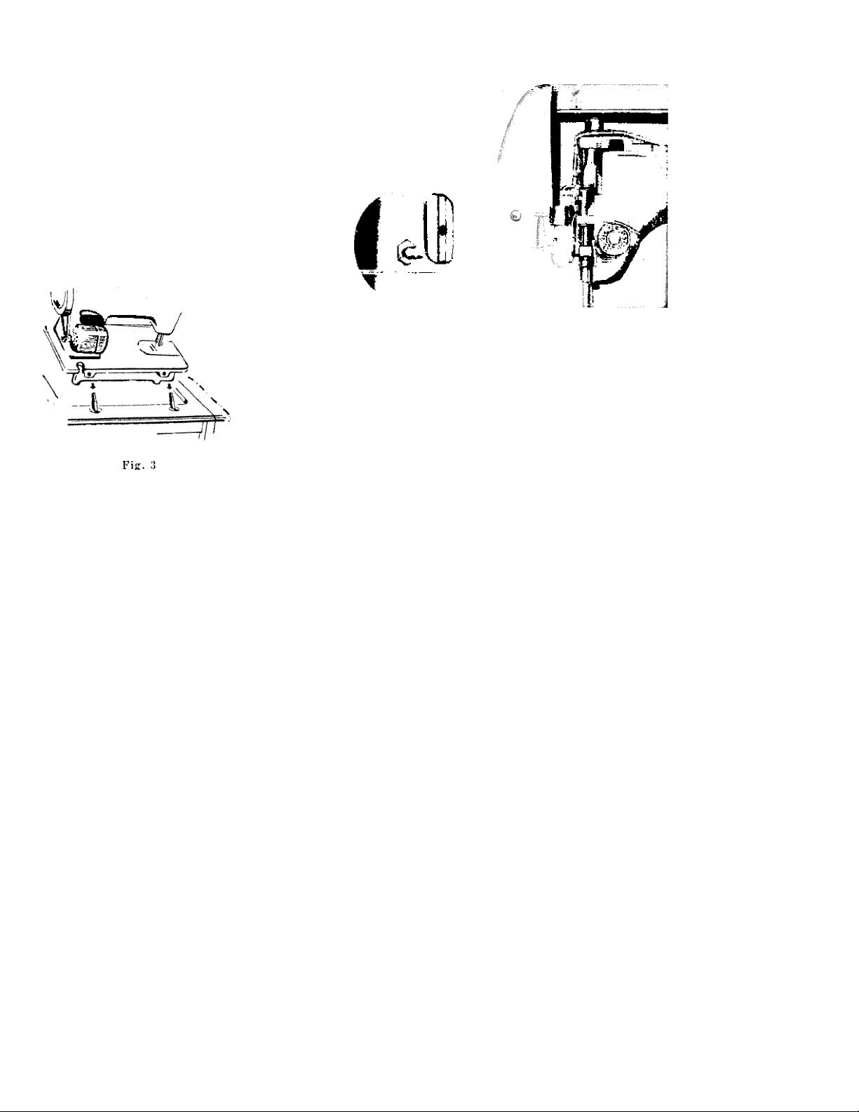
9*ti4kUUHi(^ eMead ¿*tta QaJUaet
1. Loosen the two hinge screws under the holes in the rear
edge of the machine bed. (Fig. 3)
2. Raise hinge pins in the cabinet cutout. Slip machine head
on to the pins and tighten hinge screws securely.
3. Lower machine head to front cabinet flap.
Page 5
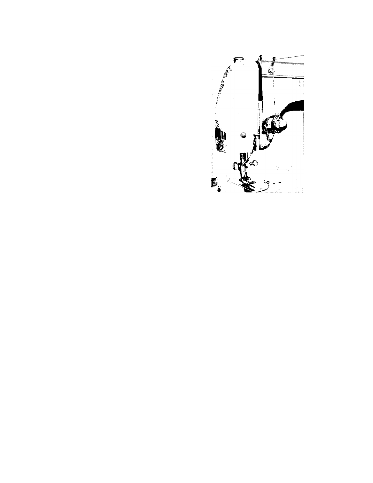
*JU^eadiHf the Maokine. & Needle
1. Turn the balance wheel toward you to raise the needle
bar to its highest position.
2. Place a spool of thread on the spool pin.
3. Lead the thread through the arm thread-guide Fig. 4).
4. Draw the thread down through the thread-guide to the
tension discs from right to left and up.
5. Draw the thread up through the check spring.
6. Draw the thread under the thread retainer bar and take
the thread up, and run the end through the eye of the
thread take-up lever from right to left.
7. Draw the thread down through the face plate guides and
then through the needle clamp thread guide.
8. Draw the end of the thread through the eye of the needle
FROM LEFT TO RIGHT, drawing it through about 3 or
4 inches. You are now ready to sew.
Pig. 4
Page 6
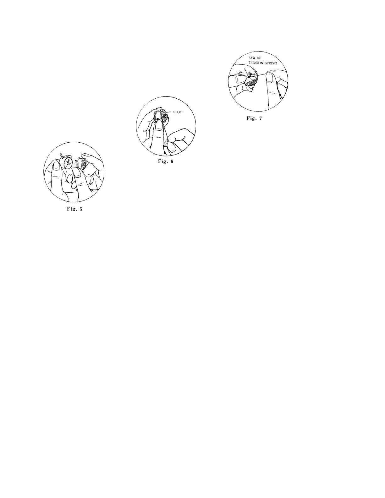
Ute BoJfJUn Qaie.
Before threadinji the bobbin case, study Fig. 5, 6 and 7 to get a
general idea as to how it is done.
1. Hold the bobbin case with your left hand and put the bobbin
into the bobbin case with your right, leaving about two inches
of the thread end unwound
(Fig. 5). As the bobbin is
being inserted in the bob
bin case, the thread flow,
you will note, in clockw'ise
(Fig. 5).
3, I'hen pull it through under the tension spring of the
bobbin case (P'ig. 6) until it enters the delivery eye
(Fig. 7).
2. While holding the bobbin
case as before, grasp the
thread end with your right
hand, guide it into the
cross slot (Fig. 6).
...
Page 7
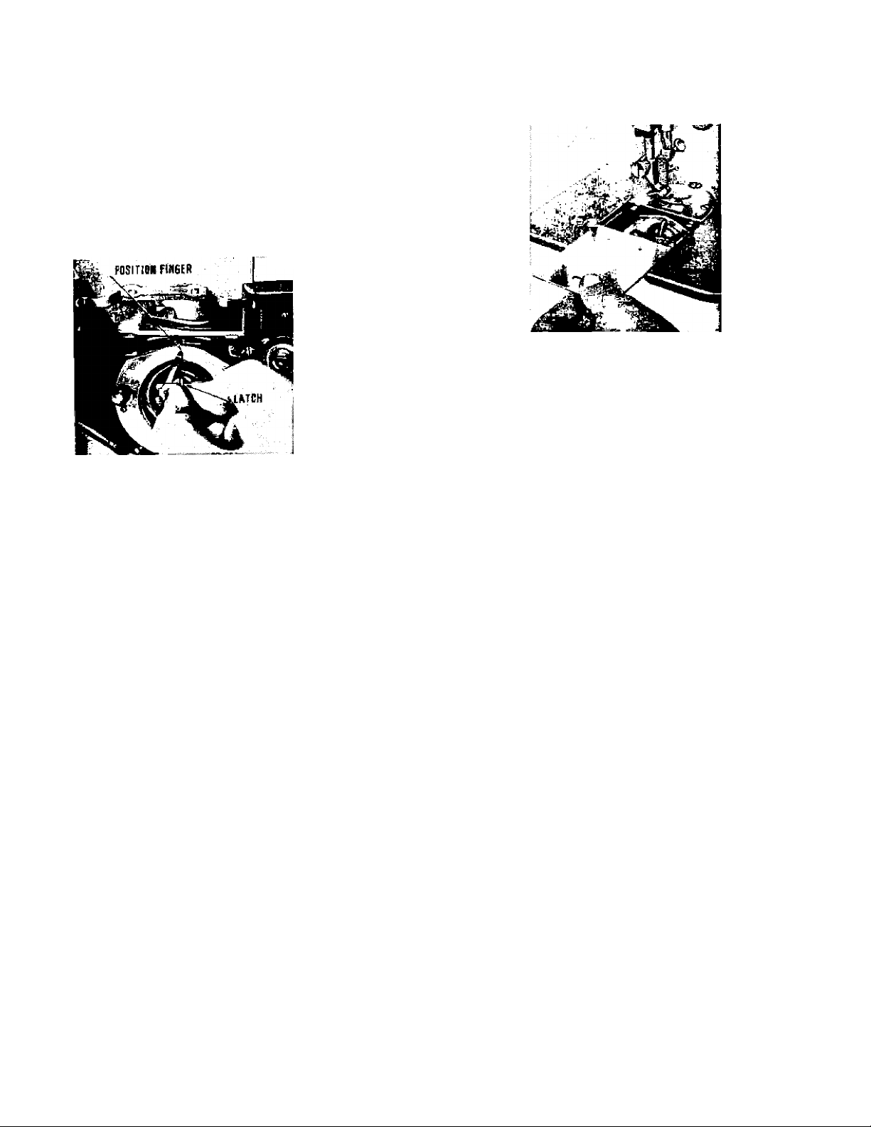
and I\em04un(f, tite RaUt-in Gale
1, Raise the presser bar by lifting the presser bar lifter.
2. Raise the needle bar to its highest position by turning the
balance wheel toward you.
3, - Pull out slide plate (Fig. 8).
4. .‘\fter threading the bobbin case, hold its latch (Fig. 9) betw^een
the thumb and forefinger of left hand, with its position finger
, . opposite the notch at
the top of the shuttle
race and replace it on
the center stud of the
shuttle (Fig. 9).
5. Then release the latch
and press the bobbin case back until the latch catches the
groove near the end of the stud.
6. Allow the end of the thread to hang free.
7. Pull back slide plate.
Fig. 8
To remove the bobbin case do all the above in reverse order.
Pig. 8
Page 8
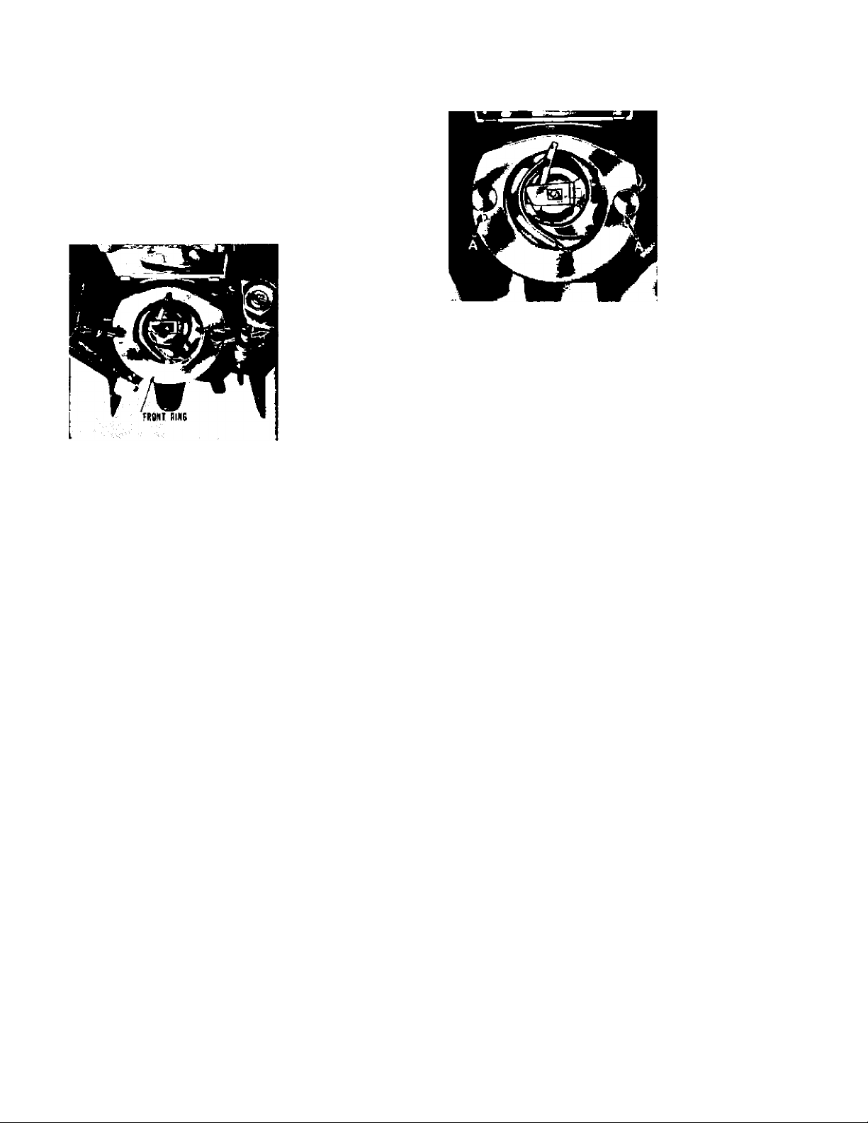
ClzaH.i4Uf, tlm Slu4>tile Rjcux.
When the thread is tangled in the race or lint gets into the
space between the shuttle and shuttle-race, this will cause
abrupt heavy running or complete stoppage of the machine.
When this occurs
L Raise the needle bar to its highest position and take the
bobbin case out.
2. Pull the KNOBS (A) on both side of shuttle race (Fig.
10 & 11) aside, then take out the outside ring and the
shuttle body with your fingers.
Fig. 11
3. After shuttle-race and bobbin case have been cleaned,
put all of them back in reverse order
Fig. 10
Page 9
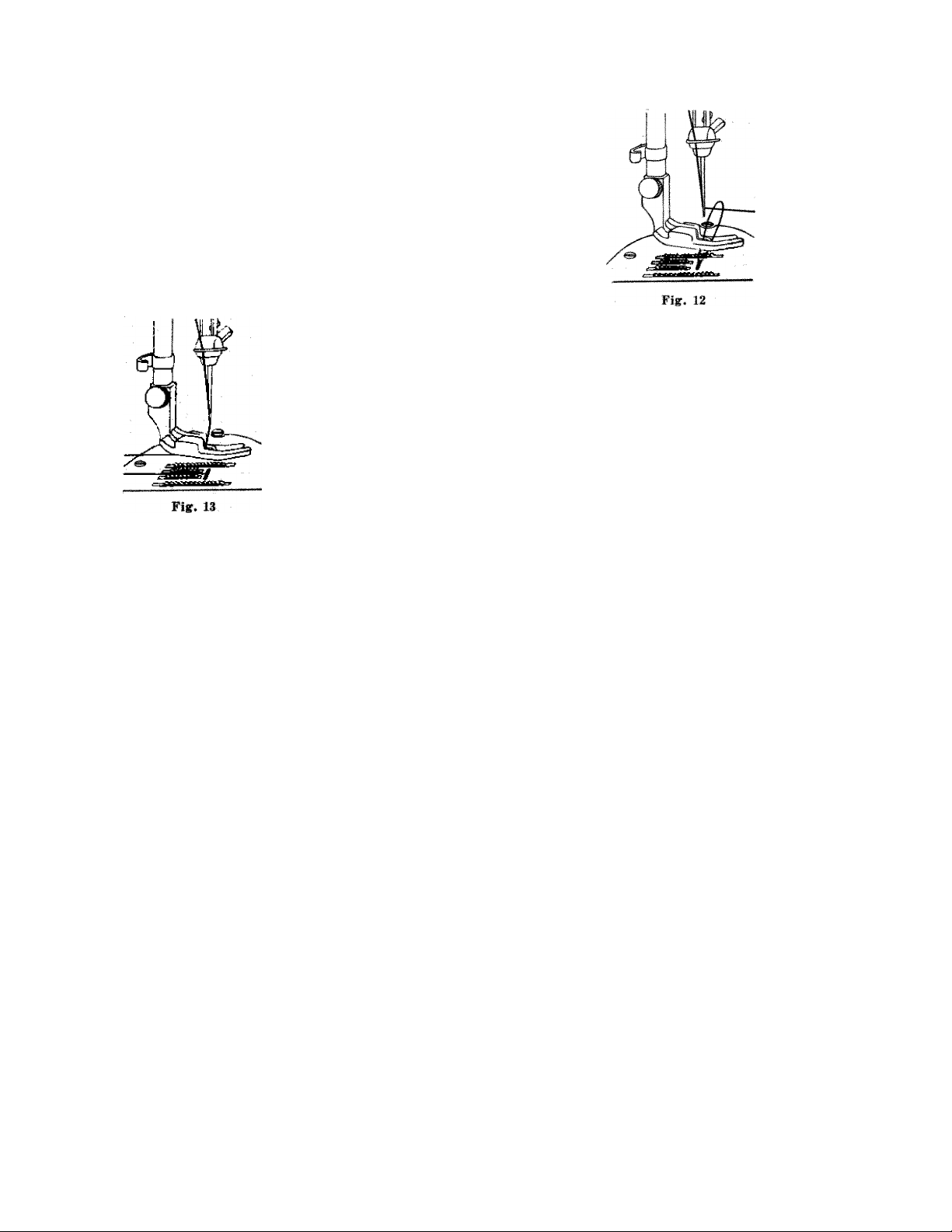
Pfmpxs/UajSf Se4AU4t^
1. Hold the end of the upper-thread with the left hand, leaving
it slack from the hand to the needle.
2. Turn the balance wheel toward you to raise the needle bar to
its highest position.
3. Pull the thread you are holding, as the lower thread will be
brought up with it through the hole in the needle plate, as
shown (Fig. 12).
4 Place both ends of the upper and lower thread to the back of
the presser foot (Fig. 13).
1. Place the fabric to be sewn beneath the presser foot.
2. Lower the presser foot by lowering the presser bar lifter.
3. Start sewing by slowly turning the balance wheel in directic n
toward you while gradually working the foot or knee control
ALWAYS TURN BALANCE WHEEL TOWARD YOU !
Page 10

Setii4iXf, tlte /Needle
1. Turn the balance wheel toward you. raising needle bar to its
highest position, and loosen the needle clamp screw.
2- Hold the needle in the left hand with the point down, and
insert the needle up into the needle clamp as far as it will go,
with its flat surface to the right; then retighten the clamp
screw (Fig. 14).
Puikh*iiio4t ^nofi ^eed i^eed Paidtla*i Pefulatan.)
The PUSHBUTTON DROP FEED is located on the bed of the machine.
It regulates the position of the feed dog for sewing very thin
material and for darning and embroidering.
1. For sewing very thin material, push down the left side
knob (B) until the red mark line reaches the surface of
the plate.
2. For darning, embroidering and tnonogramrning, push
down the left side knob (B) completely and the feed
mechanism will be lowered under the lever of the stitch
plate, so that the material can be moved freely.
3. For normal sewing, push down the right knob (A) com
pletely.
(Fig. 15)
Fif. 16
Page 11

the *7lpiead
Correct Stitch
Needle Thread Tension too strong
Needle Thread Tension too weak
Fig. 18
As all machines are correctly adjusted
before leaving the factory and read
justed before the dealer delivers them
to you, the lower tension seldom re
quires to be altered, but, if this
becomes necessary, tighten the screw
in the tension spring on the outside of
the bobbin case for more tension, or
loosen the screw slightly for lesser
tension (Fig. 16).
For ordinary stitching the tension of the upper and lower
threads should be equal so as to lock both threads in the
center of the material (Fig. 18). If one tension is stronger
than the other, imperfect stitching will result. Fine
materials require a light tension, while heavy materials
require more tension to obtain a perfect stitch.
TO INCREASE the tension, turn the thread tension dial
(Fig. 17) clockwise.
TO LE)SSEN the tension, turn the thread tension dial in
the opposite direction. (When regulating the tension
always have the presser foot down).
\
fig. U
Fig. 17
Page 12

PudJiiuitoH, (PfieAde^ ^oot PnoAiMne. Pe^niaton,]
The PUSHBUTTON DARNER is located on top of the machine
directly over the presser bar (FiR. 19 & 20). It regulates the
pressure of the presser foot for sewing very heavy material, very
thin material, and for darning and embroidering.
1. To eliminate the pressure of the presser foot for darning,
11
embroidering and inonogramming, push down the OUTSIDE
RING of the PUSHBUTTON DARNER (A) and the material
can be moved by hand while the machine is running at a
fair speed. (Fig. 19)
2. To increase the pressure of the presser foot for sewing very
heavy material, normal material and very thin material, push
the PUSHBUTTON DARNER (B) gradually down to increase
the pressure of the presser foot accordingly. (Fig. 20)
Fig. 19
Fig. 20
Page 13

12
Windiw^ the BaLLUi
3|§ To wind the bobbin, the balance wheel must be disconnected from the stitching mechanism,
the balance wheel with your left hand and turn the
stop motion knob (Fig. 22) toward you with your right
hand. This will permit the balance wheel to turn freely
while the needle bar remains motionless. The balance
wheel is now disconnected for the bobbin winding
, operation.
2. Place a spool of thread on the spool pin. Draw thread
from the spool over arm guide down ward across
,, machine from left to right. (Fig. 21)
Pass the thread through the tension disc of the bobbin
winder thread guide located at the right corner of the
machine bed.
4. Now wind the end of the thread around an empty
' bobbin seven or eight times and place the threaded
bobbin on the spindle of the bobbin winder.
5. By pressing on the bobbin winder lever, the small
rubber wheel is brought in contact with the balance
wheel. To lock into position, press bobbin winder lever
until a click is heard. The bobbin winder stop latch
is now touching the shaft of the bobbin. It holds the
bobbin in place.
6. Now manipulate your foot control or knee control in
the same manner as in sewing and when the bobbin is
completely full it will release automatically and stop
turning. Detach bobbin from spindle. Hold balance
wheel firmly with left hand and with the^ right hand
turn stop motion knob away from you until it can not
be moved any further and the needle bar moves with
the turning of the balance wheel.
Page 14

R.e^i4icUiM4f the StUcU Jle*ix^tlt
^ondAMsAxi SeiuiHif
The length of the stitch can be changed with the stitch length
dial (Fig. 23). In order to set a certain length of stitch, turn
the dial from 0~4 until the selected number on the scale is
facing the alignment mark on the stitch length dial. The
length of the stitch is increasing from 0~4. The normal
stitch is 2.
(leAfXxJatiHAf tUe. StitcU jHetUftU
/^e4*e^Ue SetiUAtf
a. Regulate the length of the stitch as for forward sewing
(see above).
b. Push reverse stitch button located above the stitch length
(Fig. 23) as far as it will go. The machine will then sew
in reverse with the same stitch length as previously select
ed. During reverse sewing, push the reverse stitch button
all the time. After release the machine resumes forward
sewing with the same stitch length.
UtA StiioU JBexu^tU Sewixuf
The stitch length dial regulates the length of the zigzag stitch for zigzag sewing in the same
manner as for straight sewing. In order to produce the "Satin Stitch” which is the closest zigzag
stitch, set the stitch length dial close to 0.
Fig. 23
13
Page 15

14
(le^44latit€c^ WuJUlt StitcU
The width of the zigzag stitch is regulated by the zigzag
width dial (Fig. 24). By turning the zigzag width dial,
the zig-zag width indicator appearing in the zigzag
width window, will move from 0~4 and the width of
the zigzag stitch will increase accordingly. In order to
revert to the previously used zigzag wddth, for ex
ample, for sewing on buttons, making buttonholes,
tacking, etc., use the twa> stoppers hw'ated above the
zigzag width wdndow. Untighten the stoppers by turn
ing the lock screw to the left. I'he stoppers can be
moved freely and set at the desired stitch width number.
Fighten the stoppers and fix them at the desired stitch
width number by turning the lock screw to the right.
Fig. 24
The stitch length dial regulaters the length of the zigzag stitch tor zigzag sewing in the same
manner as for straight sewing (See page 13). To produce the "Satin Stitch” which is the closest
zigzag stitch, set the stitch length dial close to 0 and adjust the pushbutton drop feed (feed dog
position regulator) according to the material you are sewing. (See page 9)
Page 16

tUe ^i4jc
To insert a zigzag disc into the machine follow these instructions;
1. Pull lid ;A) open.
2. Push zig zag width dial :Bi to the e.xtrenie right, and keep it
there during insertion. ‘
3. Insert disc onto a.xle ;Ci. Turn disc until it slips down and
the retaining pin ;D) enters hole ; E; in disc.
4. Release dial (B).
5. Close lid (Ah
To remove the disc, open the lid, push dial B) to the right and
pull disc up.
Now you can insert .another disc to produce another design.
Cams attached to the machine)
Fig. 26
Page 17

!î^
<> ■■ . ■■ . ' . . ' >
'' Л >
,;:Â- ^
'Afsli, #‘Éit Ai Aflfc .«A#* ASfc .;4A Sîi-A, A*'aft мЛь, A3fc, ■àais», a,«¡а*,
тМш Я0Щ mßm -»Фт. шпш. srfftwi :мФш »SA,# -тЛт :«Фёш. 5«âlfR xÆim xmiititi хчЯШк x¿:k
Cam No, 1-
Саш No. Hi:
Cam No. 3
Cam Nor !
Cain No. 5 ^
Cam No. 6 ^
Cam No. 7 i
Cam No. Й
Cam No. 9
' ..---. A -f ■■
Page 18

II» Nf'- Ш
li) Nm,. !i
ii: No. Ì3
m iio. 15
m No, 14
in No.' 15
17
./
/ \ / 'Ч .4^'
Ш No. IS
BiNo'i?
!ii No- tS
' -'ï'
Page 19

òdtHtf
To see that your machine is always in smooth running condition
you must keep it oiled at all times. No grease is required. Just
a drop of oil is sufficient at each time of oiling. Points to be oiled
are illustrated in Fig. 28A & 28B. To oil your machine thoroughly,
it will be necessary for you to open arm cover and to turn the
machine over to get to parts underneath the bed.
After oiling, run the machine at high speed for a few minutes to
let the oil penetrate to all parts.
Fig. 2XA
Fig. 2.SB
Page 20

BuiioH. Se44MH^
Turn balance wheel toward you to get needle to its highest
position. Raise presser bar and remove regular presser foot,
attach button sewing foot instead, as shown in Fig. 29. Drop
the feed dog as required for darning and embroidering. Upper
and lower thread tensions remain the same as for ordinary sewing.
Place material or garment with button under the presser foot,
so that holes in button line up with oblong hole in presser foot.
Adjust width of zigzag stitch to permit needle to pass through
center of holes in button.
Before sewing with power, turn balance wheel by hand (toward
you) making one stitch into each hole in the button and be sure that needle will not hit
Then sew five to six stitches to attach button.
When attaching four-hole buttons, first sew one set of two holes, then stitch into second
two holes and lock thread with two or three plain stitches in last hole same as described
same.
set of
:ibove.
Page 21

m
Mahitu^ /¿utionJuUed.
" ¡::L:r ^ ^ a..d set t,. 3.,,... t,^.
.u„..„,.„,e ,„, „„;;;™'I'::::"' '-»'• --
' "i:;:':„s:r;: :™;:‘,T"-';: , ■■' - ^“••“-''<
to « b,K, P„,.,b|.. ,,p„„„-,„pe „1 • ' “" »' «“'>■ W «««r:
":f ir:: 'r: :::srr:b:.r“r:::r - -»
the desired results are obtained.
NOTE: It is suKRested that you make one or two sample button
holes on a clipping of fabric, same as your garment, to test
adiustments of machine and to make corrections, if needed
Also mark with pencil or chalk the position and e.xact length
of buttonhole on garment.
To sow buttonholo, place garmoni under the b,m„„h„|e
pressor (Ob, and start the work with one end „1 ,l,e mark
Page 22

in center of half-moon shaped stitch hole of the presser foot. End of marking must point toward
you. Now start sewing left buttonhole seam and continue sewing until it reaches the gauge of
the buttonhole foot. (This gauge must be set in advance of sewing. Its distance from the needle
should be equal to the desired length of your buttonhole). Leave needle in fabric, raise presser foot
and sew'ing garment half-way around in clockwise direction. Let presser foot down and set zigzag
width as far as it can be moved. Sew four or five stitches which constitute the bar at one end of the
buttonhole. Return zig-zag width to the position between markings 1 and 2 and sew other side of
buttonhole. When arriving at end of buttonhole, again set zig-zag wfidth for sewing second bar with
also four to five stitches. , . .
Remove garment from machine and open buttonhole with buttonhole cutter included m accessories,
or use buttonhole scissors. Work cutting blades only against wooden block and be careful to ayoid
cutting the buttonhole stitching. To make reinforced buttonholes introduce gimp of propei size into
small hole right infront of the half-moon shaped stitch hole of the buttonhole presser foot.
Sew over gimp as machine makes buttonhole seams. For flat buttonholes leave thread tension pretty
much the same as for ordinary sewing.
Push dowm left pushbutton of your pushbutton drop feed, then the feed dog of the machine will drop
and permit the work to be moved by hand in any direction desired. Also remove presser foot and
raise foot lifting lever into horizontal line, and your machine is ready for embroidering and darning.
Embroidery will be done most successfully when material is strectched in an embroidery hoop.
Hold the hoop closely on the machine base with both hands and press the material with your left
index finger in the vicinity of the needle. This will help in holding down the material an wi
prevent the machine from making skip stitches. Manipulate work carefully and be sure to keep finger
out of path of needle to avoid injury. Adjust thread tensions for best appearance ^
work and slightly increase the lower thread tension (bobbin thread) to avoid the lower thieacl trom
being pulled up.
Page 23

22
^a^t/v04At tMemmefi
Turn balance wheel toward you until needle reaches its highest
point. Raise presser bar and remove regular presser foot.
Attach hemmer foot (Fig. 31). Now handle material as follows:
1. Fold over edge of material approximately %" wide, then
fold it over again in the same way for a length of about
2". Insert this folded end from beneath into spiral formed
opening (scroll) of hemmer foot. Move material back and
forth until the hem forms itself in the scroll.
2. Pull material toward you until the beginning of the hem is
Pig. 31
just below the needle.
3. Lower presser foot and begin to sew. Guide material into
hemmer foot while proceeding with work (Fig. 31).
NOTE: Do not crowd material into scroll and do not leave scroll only partly filled by material.
Feed just enough material into the hemmer foot to fill out the scroll.
Instead of a straight stitch, you can also use a zig-zag stitch for this hemming operation. Be
sure however, to adjust the width of the zig-zag stitch to be as wide as the hem itself. Using
a very long .stitch and tight tensions will produce a shell stitch.
Page 24

Se44M4i^ B^aidd,
CS': tlrX -.ach b.-,„li„,
you are sewing. Using neefe thre- d‘’1f ">«erial
enhance the beauty of your brfidinlJ;'“^ contrasting color wdl
Use the hemrner foot for doin,r f at- ,
manner: "■‘f ^^tlling and proceed ... ,u„uwmg
1.
sices facing each other. The right edire of
S™!T '>'>'""'1 'te nghOdg,. Se'°™ pC'”
2.
Sew bo,h piec» of doth „.pdhoo ,pp ^
eTiJe Of lonTf -I 'he right
gufde the hoff of.hemmer foot to
whit tie le '"«enal
while the iSredt'crf the same'iS
mmeria? "hff top pTe^ of
Onen a , ^ ""hows this detail.
^ pen and spread out material and r
FSTii thSofrortfS“' n'atd-iaTiia;;;!
hemrner foot. Sew as yt wo?id'*dn 'he scroll of the
of long toe of hemmer^ftt as hemming. Use left edge
side of it (Fig. 34). «'■'»¡"^1 seam run alonf
in the iollowing
TOP PIECE
BOTTOM PIECE -
--------
Fig:. .33
back on machine right sides
Page 25

24
Qlatk Qi44d&
I'tK' dolh Kuide (FiR. 35) serves as a .ijuitle for straigiu stitch
ing when making wide licms, deep tucks or seam widths which
are greater than presscr foot allows.
It is attaclied to machine as illustnited.
'Fhe (itiiller (Fig. ?S) will enable you to sew e{|ui-distant lines on
jtadded ftibrics without the necessity of marking them in .adwince.
'Fo atlacli the ciuilter to the presser bar of the macliine, first pull long
wire hook out of horse-shoe shtijted clamp. Slide the clamp oti the
presser bar from behind and above ordinary ¡tresser foot, and push
the wire liook into its previous place.
Adjust wire fiook to desired disttince from needle :uid bring it to press
into ftibric. d'hen lighten thumb screw e.xlending bttekward from
horse-shoe shnperl chimp to lock quiller ¡illachment into [tlace. When
sewdiig, wire hook should follow preceding hue of stitching.
Zig-zag stitch (|uilling is done the same as sirthglu stilcii (|uilting with
Fig. 36
the exception of the position of the zig-zag stitch dial vvh.ich should
be set loi' tiny desired width of zig-zag stitch.
2.HiU4*t£^
Page 26

Ga444ei, Q<mu$um %i^ic44lUei.
BREAKING OP THE UPPER THREAD:
1. Incorrect threading
3. Faulty needle, or needle set incorrectly
v5. Needle eye too small for thread used
7. Starting the machine with the take up lever at its highest position
2. Upper thread tension too tight
4. Needle brushing against presser foot or other
attachments
rt. Starting the machine suddenly or with a jerk
BREAKING OF THE LOWER THREAD:
1. Incorrect threading of the bobbin case 2 Lower thread tension too tight
3. Bobbin being wound too fully # Rough edge of hole in needle plate caused by
improper needle action
BREAKING OF THE NEEDLE:
1. Pulling the fabric while machine is running, thus causing the needle to strike the needle plate
2. Using bent needle
SKIPPING STITCHES:
1. Using bent or blunt needles 2. Needle inserted incorrectly
3. Needle threaded improperly 4. Using wrong sized needle
5. Pressure of presser foot insufficient, especially when sewing heavy material
UNEVEN STITCHES:
^ Presser foot not resting evenly on material 2. Feed dog not being high enough
^ Too short stitches used 4. Pulling the cloth while the machine is running
9 Using a too fine a needle with a too coarse thread
Page 27

Sizes & Grades of
-Needles
B or 11
(Medium-Fine)
V2 or 14
(Medium)
_ 1 or 16
(Light-Heavy)
2 or 18
(Medium-Heavy)
3 or 19
(Heavy)
4 or 21
(Extra- Heavy)
needle and thread sizes (USE 1S , .
--------------‘L'SE 15>1 needle ONLY)
Q /vf ' ~r '
"TypTSTFaBriT
....:.........
For house fabrics.
dresses, aprons, curtains^ «'askable cotton
fatoc «'eight woolens,'draperies. '
........................
Lor ba,s. canvas, coarse cloths and heavy ,oods.
__
Done
A& B
Twist
Frimed in Japa„
 Loading...