

Page 1

PR-10159
UL / ULC
Pressure
Reducing Valve
106-PR-10159
S106-PR-10159
A106-RP-10159
OPERATING INSTRUCTIONS MANUAL
TABLE OF CONTENTS PAGE
General Information / Operation 2
Installation 3-4
(S)106-PG – Single Chamber,
Hydraulically Operated Valve 5-6
106-PR Pressure Reducing Pilot 7
Parts and Dimensions 8-11
SA106-PR-10159
WARNING:
1. Read and follow instructions carefully. Proper training and periodic review
regarding the use of this equipment is essential to prevent possible serious injury
and/or property damage. The instructions contained herein were developed for
using this equipment on ttings manufactured by Mueller Co. only, and may not be
applicable for any other use.
2. DO NOT exceed the pressure ratings of any components or equipment. Exceeding
the rated pressure may result in serious injury and/or property damage.
3. Safety goggles and other appropriate protective gear should be used. Failure to do
so could result in serious injury.
F 13902 3/19
Page 2
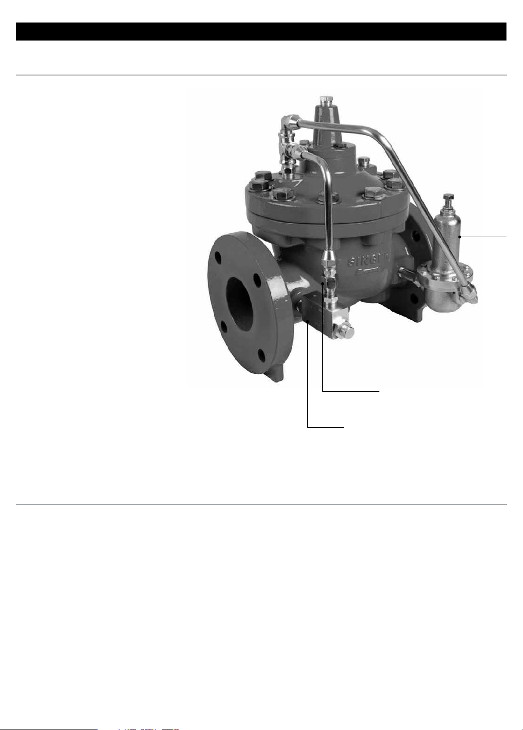
PR-10159 PRESSURE REDUCING VALVE
OVERVIEW
Model PR-10159 is a pilot operated
pressure reducing valve designed
to automatically reduce a high inlet
pressure to a lower outlet pressure.
The valve will maintain a relatively
steady downstream pressure
regardless of fluctuations in the
supply pressure or flow rate.
Maximum Pressure
– For sizes up to and including
4", maximum inlet pressure is
300 psig.
– For the 6" and 8" sizes, the
maximum inlet pressure is
300 psig.
– The outlet pressure setting range
for all sizes is 30-165 psig and
shall not exceed 175 psig.
NOTE: With any manufactured
product there is a risk of
malfunction in service, whether
by operating conditions such as a
plugged strainer or normal wear
and tear. We recommend regular
maintenance with frequency to
suit the importance to customer's
application. We draw attention
to our warranty which limits
our responsibility to defects in
workmanship and materials
only. Visit singervalve.com for
warranty details.
General Information / Operation
Pilot
Fixed
Restriction
Strainer
OPERATION
Model PR-10159 reacts to changes
in downstream pressure via Pilot.
Since the capacity of Pilot is much
larger than that of Fixed Restriction,
the state of the pilot (open or
closed) determines whether the
Main Valve is open or closed. Refer
to Model 106-PG 'Operation' for
more details.
High Downstream Pressure
When there is no demand (and
the downstream pressure is at, or
higher than the setting of Pressure
Reducing Pilot), Pilot closes.
Flow through the pilot circuit is
then directed to the bonnet through
Fixed Restriction and Flow Stabilizer,
pressurizing the bonnet and closing
Main Valve.
Low Downstream Pressure
When flow is required, and
downstream pressure is lower than
the setting of Pilot, the pilot opens.
Flow in the pilot circuit is greater
from the bonnet to downstream.
The bonnet therefore depressurizes,
opening Main Valve.
At zero flow conditions, the
maximum increase in downstream
pressure will be within 10% of the
set pressure or will not exceed
7 psi.
2
Modulating
Under flowing conditions below the
set point of Pilot, the pilot reacts
to small changes in downstream
pressure and modulates the bonnet
pressure (and Main Valve position)
as required to keep the downstream
pressure constant.
The speed of opening and closing
of the main valve depends on the
setting of Model 26 Flow Stabilizer.
Refer to Model 26 instructions for
details and adjustment.
Page 3
PR-10159 PRESSURE REDUCING VALVE
INSTALLATION AND ADJUSTING PROCEDURE
Installation
Installation is to be done in
accordance with NFPA 13, the
Standard for Installation of Sprinkler
Systems, or NFPA 14, the Standard
for Installation of Standpipe and
Hose Systems, as applicable.
1. Model S106-PR-10159 shall be
installed on systems not exceeding
the valve end configurations
working capabilities.
2. Pressure gauges MUST be
installed on the inlet and outlet
piping of the valve.
3. If valve is for use with Standpipe
and Hose Systems, refer to
NFPA 14 for minimum
installation requirements.
2
3
4. Refer to (S)106-PG 'Installation'
for other installation requirements.
5. Installation with loosely held
piping and/or elbows close to the
valve may cause the valve
to pulsate.
NOTE: For a valve intended for use
in sprinkler systems, as indicated
by NFPA 13:
A relief valve at least 1/2" (13 mm)
in size with adequate drainage is
to be installed on the downstream
side of this valve. The relief valve
must be set above the "lock-up" or
"zero flow" shutoff pressure which
is approximately between 4 to
10 psi higher than set pressure.
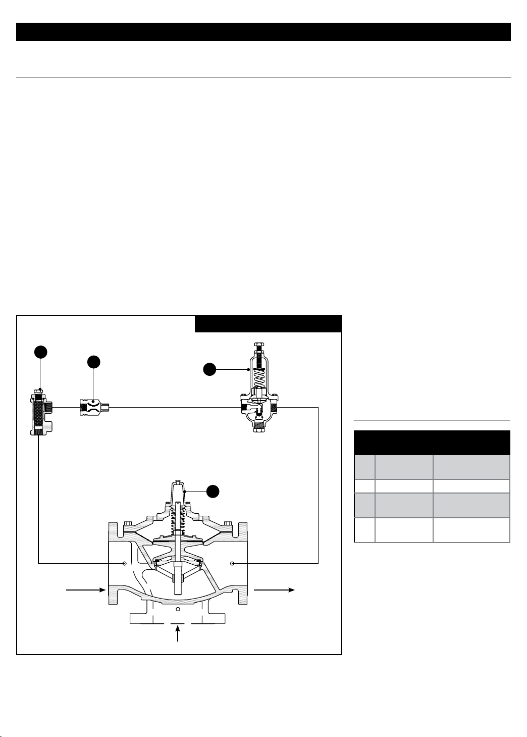
DIAGRAM 1. CONTROL VALVE SCHEMATIC
4
Adjustment
1. Open Isolating Valves (2), (5) and
(7) (if so equipped).
2. Crack outlet stop valve and
slowly open inlet stop valve wide.
3. Bleed air from Main Valve bonnet.
See (S)106-PG 'Installation'.
4. Open outlet stop valve wide.
5. Set reduced (downstream)
pressure by turning Pilot (6) adjusting
screw: To increase pressure, turn
adjusting screw clockwise.
- To reduce pressure, turn adjusting
screw counter-clockwise.
NOTE: There must be flow through
the valve when pressure is adjusted.
6. If the valve does not open
(pressure remains low), check the
adjustment of Pressure Reducing
Pilot (6).
7. If the valve begins to oscillate
or hunt, bleed air from Main Valve
bonnet. See (S)106-PG 'Installation'.
1
Inlet
Inlet
Outlet
NOTE: For dimension information and material specifications see
component data sheets.
PARTS LIST
ID PART DESCRIPTION
1 Main Valve
2 Strainer J0098A
3
4
Tubing Option: Copper.
Fixed
Restriction
Pressure
Reducing Pilot
(S)106-PG or (S)
A106-PG
Model 161-PR,
Range 30-165 psi
3
Page 4
PR-10159 PRESSURE REDUCING VALVE
CARE / MAINTENANCE
Maintenance & Troubleshooting
Testing after installation is to be
done in accordance with NFPA 13 or
NFPA 14, or both NFPA 13 and 14,
whichever is applicable, and tested
periodically thereafter in accordance
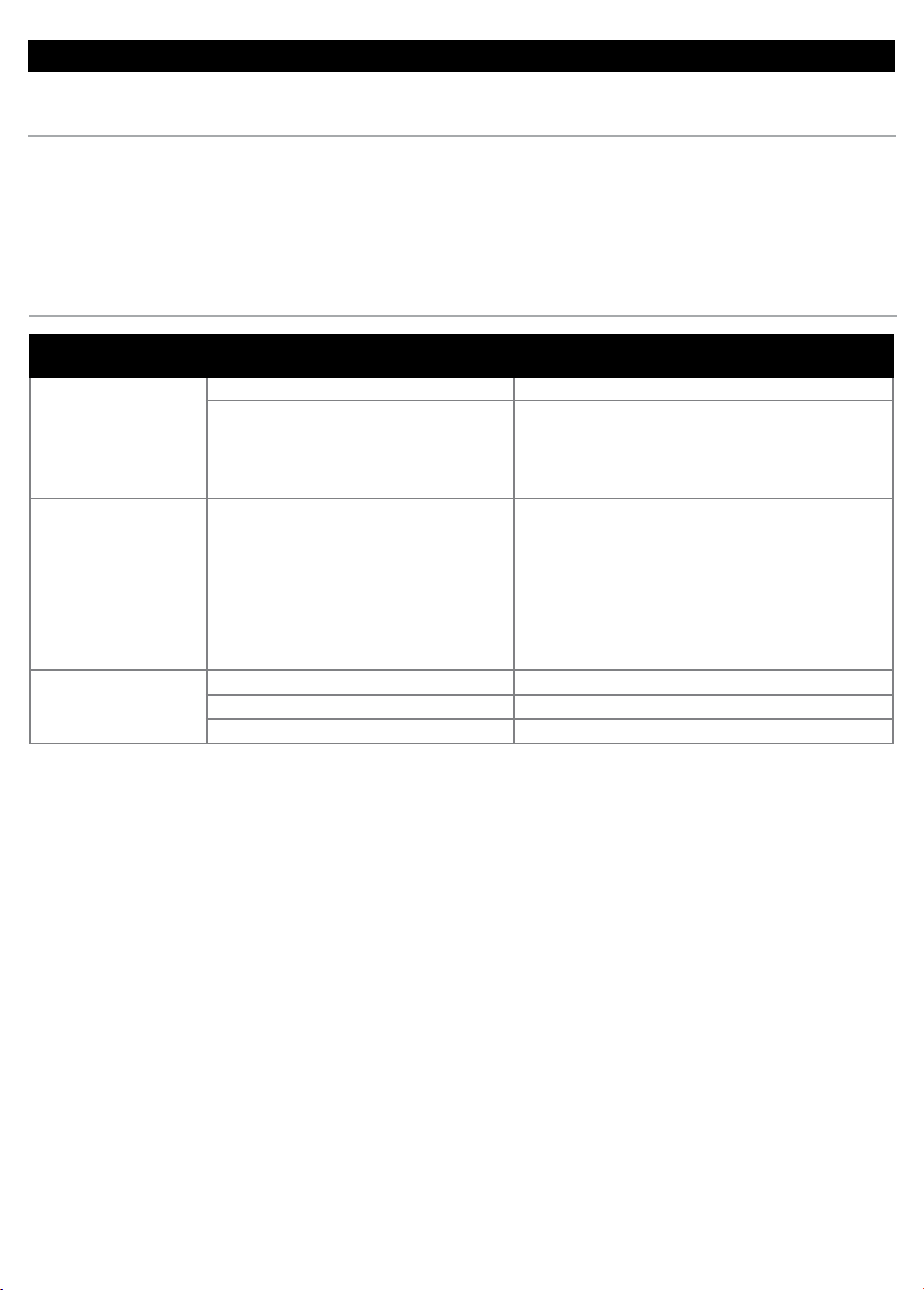
TROUBLESHOOTING
PROBLEM CAUSE SOLUTION
1. Insufcient inlet pressure 1. Check inlet pressure source and increase as needed
2. Pressure in the bonnet not being released: 2. Try the following:
Valve Fails to Open
Valve Fails to Close
Pulsations Occurring
a) Isolating valves on pilot lines closed a) Open valves
b) Pilot components not functioning b) Refer to specic instructions on pilot components
c) Foreign material in pilot system c) Clear obstruction
1. Lack of pressure in bonnet due to: 1. Try the following:
a) Pilot components not functioning a) Refer to specic instructions on pilot components
b) Foreign material in pilot system b) Clear obstructions
c) Ruptured diaphragm c) Replace worn parts
d) Obstruction in the valve d) Remove obstructions
e) Worn main valve disc e) Replace disc
f) Plugged pilot strainer f) Flush strainer free of debris
1. Air in the bonnet 1. Vent air (refer to “Installation” #16)
2. Improper adjustments to pilot components 2. Refer to specic instructions on pilot components
3. Valve oversized 3. Smaller valve may be more suitable
with NFPA 25, the Standard
for Inspection, Testing, and
Maintenance for Water-Based Fire
Protection Systems requirements.
In addition to service suggestions
listed under NFPA 25 refer to
(S)106-PG Service Suggestions.
4
Page 5
PR-10159 PRESSURE REDUCING VALVE
OVERVIEW
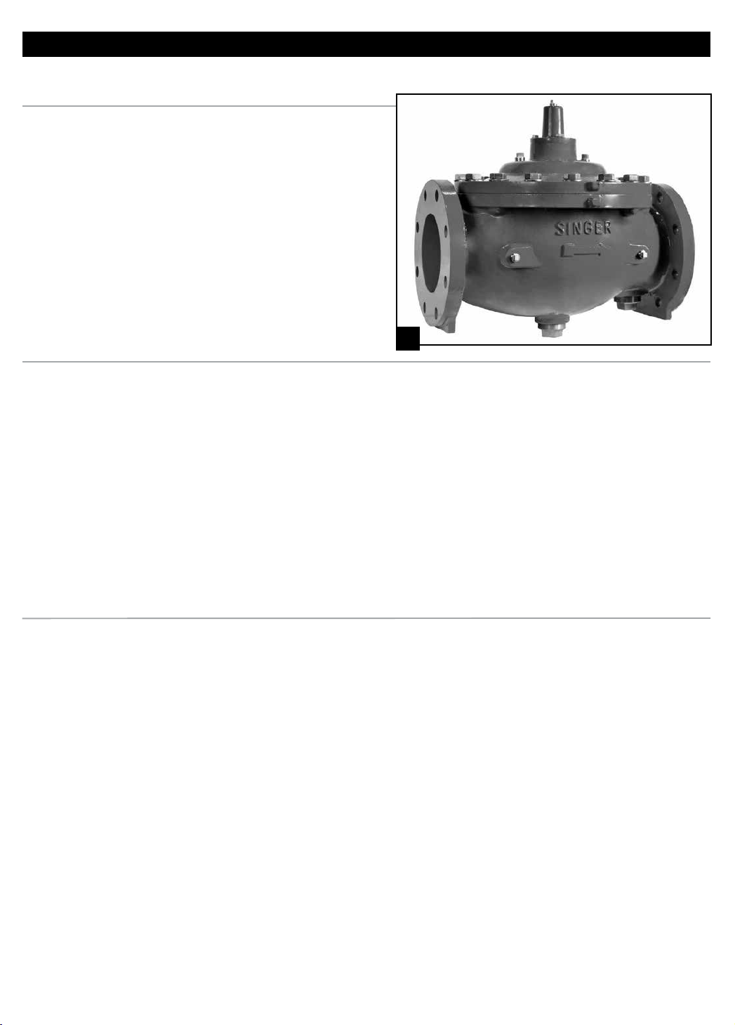
Model 106-PG Main Valve Body Parts
The 106-PG (flat diaphragm)
and (S)106 -PG (single rolling
diaphragm) valves (Pic. A) are
the main valves used for Singer®
control valve systems.
Unless otherwise specified,
the valve is assembled with
components suitable for water
service up to 180° F (80° C). For
other service conditions, contact
your Singer representative.
OPERATION
Opening and Closing
The opening and closing action
is performed by the inner valve
assembly, controlled by the
pressure in the bonnet chamber
above the diaphragm.
The valve opens when:
a) Bonnet chamber is vented
downstream with a minimal
pressure drop of 10 psi across the
main valve.
NOTE: This valve
must be stored
indoors, away from
direct sunlight.
A.
b) Bonnet chamber is vented
to atmosphere with a minimal
pressure drop of 5 psi across the
main valve.
The valve closes when:
a) Bonnet is pressurized by
upstream pressure or an external
pressure (equal to or higher than
line pressure), sealing the inner
valve to the seat area tight.
Modulating
The valve can be made to modulate
by varying the bonnet pressure
between inlet pressure and outlet
pressure. This is done by the
pilot circuit.
INSTALLATION
1. Use washers under nuts when
bolting valve flanges to pipe flanges
to protect the Epoxy Coating.
2. It is recommended that valves
be installed in a horizontal pipe with
the bonnet up for more convenient
access for maintenance. However,
smaller valves (6" and smaller) may
be installed in a vertical pipe if the
order states the orientation.
3. A stable, continuous source of
pressure is necessary to operate a
pilot operated control valve.
4. Operating fluid must be clean
and free of air.
5. Under high velocity conditions,
when the pressure signal is located
at main valve inlet, it may be
adversely affected. When possible,
a more suitable location should be
used. For example, a relief valve will
operate more effectively and control
more accurately if the operating
pressure and sensing pressure is
connected to the header.
6. Six pipe diameters of straight
pipe on the inlet of any control
valve is recommended but:
a) Fully open Gate Valve can be
installed on the inlet of a valve,
provided it is used as an isolating
valve and never used in partially
open condition.
b) A Butterfly Valve with stem
horizontal cannot be installed in
the inlet of a control valve unless
operating pressure and sensing
lines are connected upstream of
the butterfly valve, in a location that
gives true system pressure.
c) A Butterfly Valve with stem
vertical can be installed in the inlet
of a control valve as long as velocity
does not exceed 15 ft / sec. The
butterfly valve can not be used for
throttling. If problems develop at
high flows, operating pressure and
possible sensing can be connected
upstream of the butterfly valve, in a
location that gives true
system pressure.
d) A Control Valve can be installed
with no straight pipe on the inlet
if the operating and sensing lines
are connected to a location that
gives true system pressure. The
connection point should be made
at the pipe center line to avoid air
pick-up at the top of the pipe.
7. This valve is shipped with air
pressure in the bonnet. Do not
open the Bonnet Isolating Valve
until the valve has been installed
and ready for pressurization.
5
Page 6

PR-10159 PRESSURE REDUCING VALVE
(S)106-PG – Single Chamber, Hydraulically Operated Valve
INSTALLATION (CONT.)
8. It is possible that diaphragms
may take a set after shipping and
storage. It is highly recommended
that Bonnet and Body Bolts or Nuts
be tightened after installation but
before pressurizing the valve. If a
leak develops after pressurizing,
de-pressurize the valve and tighten
the bolts or nuts.
9. For most convenient operation
and maintenance, line isolation
valves should be installed.
10. A suitable bypass should be
provided to allow for servicing of the
valve without interrupting the flow.
MAINTENANCE
The Singer® Model (S)106-PG
requires minimal maintenance.
All parts are accessible for
inspection and repair without
removing the valve from the line.
1. Close upstream and downstream
isolating valves.
11. Install pressure gauges
upstream and/or downstream
of valve as appropriate. This will
facilitate ease of setting the
pilot system.
12. A strainer with a suitable
basket should be installed ahead of
the valve to protect it from
foreign material.
13. Sufficient space should be
provided around the valve
for disassembly.
14. Flush system of all debris
before installing the valve.
15. Check direction of flow (inlet
of valve is marked OR an arrow
2. Disconnect body and bonnet
pilot lines.
3. Remove bonnet. If bonnet does
not come free readily, it can be
pried loose with a small pry-bar.
4. Remove inner valve assembly for
inspection. Do not remove seat ring
on the side of body indicates flow
direction) and install the
valve accordingly.
16. Vent air from the bonnet:
Valves with no Limit Switch:
Loosen pipe plug at the centre of
the bonnet to bleed air. If equipped
with position indicator, use bleedvalve on indicator.
Valves with Limit Switch:
Refer to Drawing and use bleed
screw to vent air.
unless inspection shows that it is
damaged or debris is found below
the guide assembly. Be very careful
not to damage the epoxy coating
when removing and installing the
inner valve assembly.
5. Replace worn or defective parts
as necessary and reassemble.
6
Page 7
PR-10159 PRESSURE REDUCING VALVE
DESCRIPTION / OPERATION
161-PR Pressure Reducing Pilot
Model 161-PR is a direct acting,
spring and diaphragm type pressure
reducing pilot. The valve is held
open by an adjustable spring.
INSTALLATION / ADJUSTMENT
1. Install the Pilot as shown in the
enclosed schematic or drawing.
2. Note the direction of flow and
install the valve accordingly.
3. The valve should be installed
with the adjusting screw
pointing up.
MAINTENANCE
Disassembly
1. Close upstream and downstream
isolating valves.
2. Remove the entire pilot from
the system.
3. Remove the adjusting screw.
4. Remove the Body Screws and
remove the spring casing assembly.
5. Loosen the diaphragm if it
adheres to the body and remove the
Stem / Yoke assembly. Be careful
to avoid damage to the stem as
Operation
The setpoint of the Model 161-PR
is determined by the compression
of Spring. The spring provides
Adjustment
1. Turning the Adjusting Screw (#17,
page 10) clockwise increases the
setting of the pilot, providing a
higher downstream pressure.
2. Turning Adjusting Screw
counter-clockwise decreases the
setting of the pilot, providing a lower
downstream pressure.
any additional friction between the
Stem and Guide Bushing can
affect performance.
Inner Valve Replacement
1. Hold the Inner Valve hex in
a vise and use a screwdriver or
similar tool to turn the Yoke.
Diaphragm Replacement
1. Hold the inner valve hex in a
vise and use a screwdriver to turn
the stem counter-clockwise using
the slot at the top of Stem.
a constant downward force on
diaphragm, while the outlet pressure
acting under the diaphragm opposes
the spring, which closes valve.
Note: Range of adjustments and
corresponding pressures are also
shown on the name plate on the
body of the pilot.
SPRING RANGE (PSI)
30 – 165 26
If required, use a secondscrewdriver
or similar tool at the Yoke to prevent
the yoke from turning. When doing
so, take extra care to avoid damage
to the stem guiding surface.
2. Replace the diaphragm in the
same orientation as the original
one, straddling the legs of the yoke.
Assembly
Reassembly is the reverse of
disassembly. Ensure that parts are
replaced in the sequence shown on
the drawing.
ADJUSTMENT
(PSI / TURN)
TESTING PROCEDURE
1. Connect a source of air or water
to the inlet.
2. Attach a 3/8" line with a
pressure gauge and shut-off valve
to the outlet.
3. Back off the adjusting screw, then
proceed to turn it in. The gauge
should show an increase within the
range marked on the valve.
4. Open the shut-off valve slightly
and bleed flow to atmosphere.
Pressure should drop slightly and
return to setting when the shut-off
valve is closed. This check should
be repeated at various settings.
TROUBLESHOOTING
PROBLEM CAUSE SOLUTION
Main Valve Fails to Open 1. Pilot setting too low 1. Raise setting (turn adjusting screw clockwise)
1. Pilot setting too high 1. Lower setting (turn adjusting screw counter-clockwise)
Main Valve Fails to Close
2. Obstruction on seat 2. Locate and remove obstruction
3. Ruptured diaphragm 3. Replace diaphragm
4. Worn inner valve 4. Replace inner valve
7
Page 8
PR-10159 PRESSURE REDUCING VALVE
20
18 52
13
12
11
46
45
49
9
10
8
6
6
17
44
7
5
4
7
5
3
14
19
Two Piece Seat &
Bottom Guide Detail
One Piece Seat &
Bottom Guide Detail
15
17 44
3
14
2
16
1
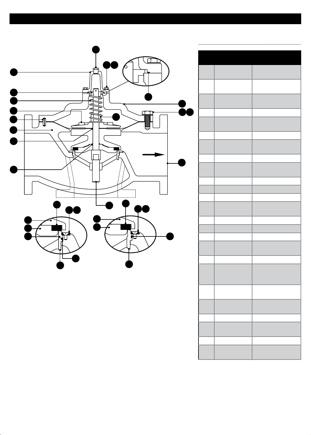
PARTS LIST
ID DESCRIPTION MATERIAL
1 Body
2 Bonnet
3 Seat Ring
51
4 Stem Stainless Steel
5 Disc Retainer
6 Resilient Disc EPDM or Buna-N
7 Inner Valve
8* Diaphragm EPDM or Buna-N
9 Clamp Plate
10 Stem Nut Brass B-16
11 Spring Stainless Steel
12 Guide Bushing Brass B-16
13 Stem Cap
14* Seat Ring Seal Buna-N
15* Stem Cap Seal Buna-N
16 Bonnet Bolt Stainless Steel
17
18 Stem Screw Stainless Steel
19 Bottom Guide
44
45*
46 Locating Pin Stainless Steel
49*
51 Bonnet Washer Stainless Steel
52
Seat Ring
Screws
Seat Retaining
Washer
Diaphragm
Seal
Disc Retainer
Seal
Stem Cap
Washer
Stainless Steel (See
Stainless Steel 2
Bronze (See Note
Parts
Ductile
Iron / NAB / SS
Ductile
Iron / NAB / SS
Note 2)
Ductile Iron (See
Note 3)
Ductile
Iron / NAB / SS
Ductile
Iron / NAB / SS
Ductile
Iron / NAB / SS
Ductile Iron &
4)
Stainless Steel
(See Note 1)
Buna-N
Buna-N
Stainless Steel
*Recommended spare parts (included in Rebuild Kit).
NOTES:
1. Not required on size 2 - 1/2", (One piece seat ring
and guide, shown as item 3).
2. On sizes 2 - 1/2"– 8" items 3 & 19 may be one
piece; material - Stainless Steel.
3. On sizes 2 - 1/2" & 3", material is brass B-16. On
size 4", material is bronze.
4. On size 3", material is bronze B-62.
8
Page 9
SINGER
SINGER
PR-10159 PRESSURE REDUCING VALVE
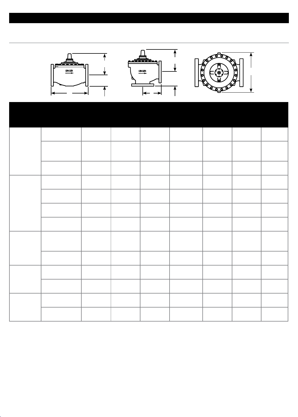
DIMENSIONS
Dimensions
E
D
A
B
E
F
106-PG & A106-PG GLOBE GLOBE & ANGLE ANGLE
A D E C B E F
2 - 1/2"
65 mm
3"
80 mm
4"
100 mm
6"
150 mm
8"
200 mm
NPT / BSPT
150F / PN10,
PN16, PN25,
PN40
300F
NPT / BSPT
150F
300F
PN10, PN16,
PN25, PN40
150F / PN10,
PN16, PN25,
PN40
300F
150F / PN10,
PN16
300F / PN25,
PN40
150F / PN10,
PN16
300F / PN25,
PN40
11"
279 mm
11"
279 mm
11.63"
295 mm
13.50"
343 mm
12"
305 mm
13.25"
337 mm
12.25"
311 mm
15"
381 mm
15.63"
397 mm
20"
508 mm
21"
533 mm
25.38"
645 mm
26.38"
670 mm
3.38"
86 mm
3.50"
89 mm
3.75"
95 mm
3.68" 94
mm
3.75"
95 mm
4.13"
105 mm
7.50"
191 mm
7.50"
191 mm
7.50"
191 mm
8" 203 mm
8" 203 mm
8" 203 mm
4" 102 mm 8" 203 mm
4.60"
117 mm
5.09"
129 mm
5.60"
142 mm
6.34"
161 mm
7.63"
194 mm
7.88"
200 mm
9.15"
232 mm
9.15"
232 mm
11.75"
299 mm
11.75"
299 mm
14.91"
379 mm
14.91"
379 mm
8.19"
208 mm
8.19"
208 mm
8.19"
208 mm
5.50"
140 mm
5.50"
140 mm
5.88"
149 mm
9.25" 235 mm6.63" 168
mm
9.25"
235 mm
9.25"
235 mm
9.25"
235 mm
10.88"
276 mm
10.88"
276 mm
16.63"
422 mm
16.63"
422 mm
21.63"
549 mm
21.63"
549 mm
6" 152 mm 8" 203 mm
6.38"
162 mm
6.38"
162 mm
7.50"
191 mm
7.88"
200 mm
10"
254 mm
10.50"
267 mm
12.75"
324 mm
13.25"
337 mm
C
7.50"
191 mm
7.50"
191 mm
7.50"
191 mm
8" 203 mm
8" 203 mm
8" 203 mm
9.15"
232 mm
9.15"
232 mm
11.75"
299 mm
11.75"
299 mm
14.91"
379 mm
14.91"
379 mm
4"
102 mm
4"
102 mm
4.31"
110 mm
4.63" 118
mm
4"
102 mm
4.38"
111 mm
4.38"
111 mm
5"
127 mm
5.31"
135 mm
6"
152 mm
6.50"
165 mm
8"
203 mm
8.50"
216 mm
9
Page 10
PR-10159 PRESSURE REDUCING VALVE
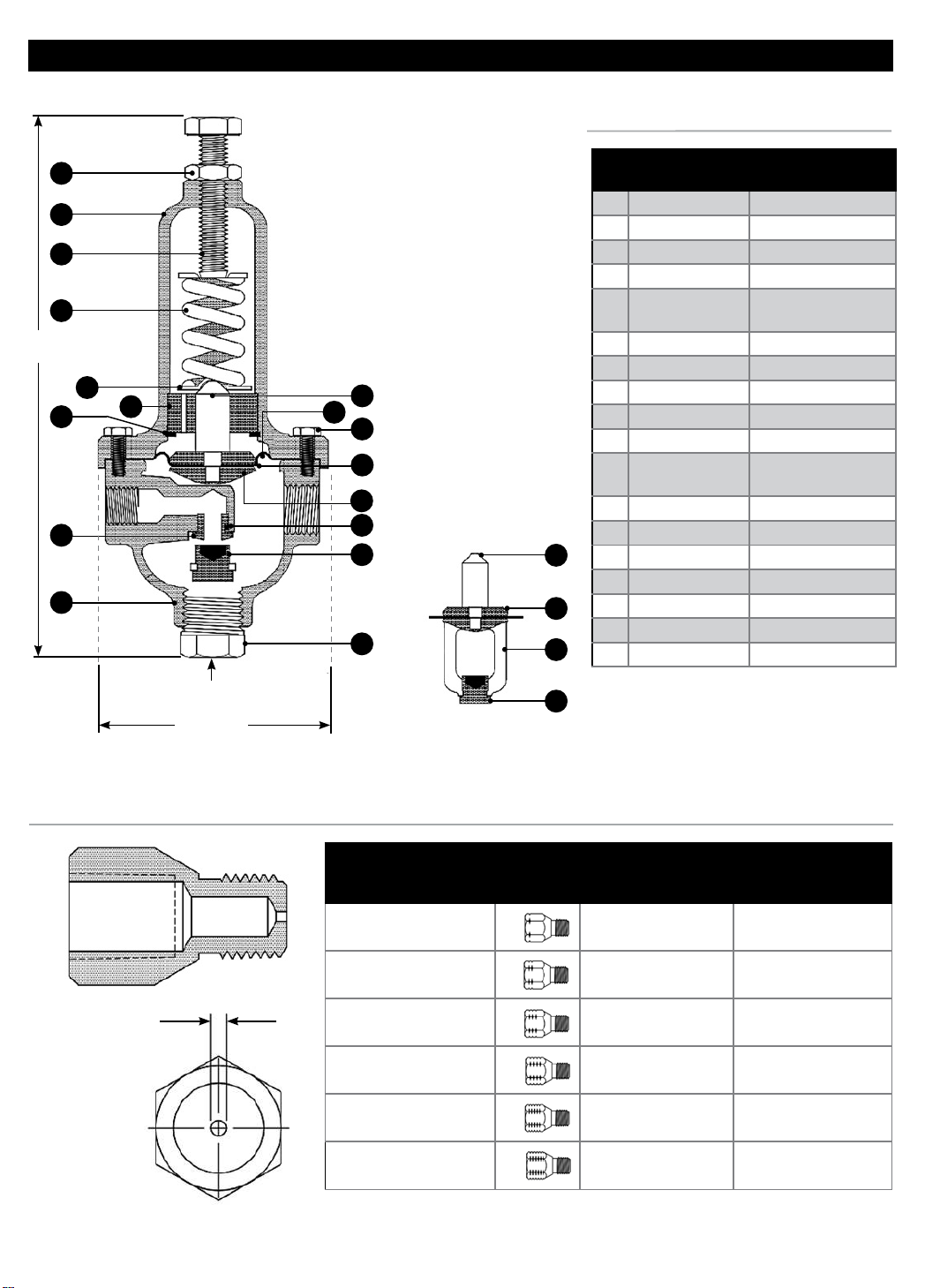
161-PR Pressure Reducing Pilot Parts & Dimensions
PARTS LIST
16
8
17
13
9"
Max
9
Inlet
3/8" NPT
18
1
14
10
ID DESCRIPTION MATERIAL
1 Body Stainless Steel
2 Diaphragm EPDM
3 Outlet Connector Stainless Steel
4 Stem Stainless Steel
5 Inner Valve
6 Yo ke Stainless Steel
7 Clamp Plate Stainless Steel
4
2
11
7
Outlet
3/8" NPT
6
19
5
4
7
20
6
8 Spring Casing Stainless Steel
9 Retaining Ring Stainless Steel
10 Guide Bushing Delrin
Casing Screw
11
13 Spring Spring Steel
14 Spring Step (2) Stainless Steel
16 Locknut Stainless Steel
17 Adjusting Screw Stainless Steel
18 Seat Ring Stainless Steel
19 Seat Ring Seal Buna-N
20 Plug, 1/2 NPT Brass
(8)
Stainless Steel and
EPDM
Stainless Steel
FIXED RESTRICTION
1/4"
NPT
Outlet
3/8" NPT
3 - 3/16" Ø
1/4" NPT
"A" Ø
"A" DIAMETER
1/16" (1.6 mm)
3/32" (2.4 mm)
1/8" (3.2 mm)
1/4" (6.4 mm)
7/64" (2.8 mm)
3/16" (4.8 mm)
NO. OF ID
GROOVES
1
2
3
4
5
6
5
STAINLESS STEEL 303
PART NUMBER
M1009E-SS M1009E-S3
M1149E-SS M1149E-S3
M1010E-SS M1010E-S3
M1997A-SS M1997A-S3
M2023A-SS M2023A-S3
M1813B-SS M1813B-S3
STAINLESS STEEL 316
PART NUMBER
10
Page 11
PR-10159 PRESSURE REDUCING VALVE
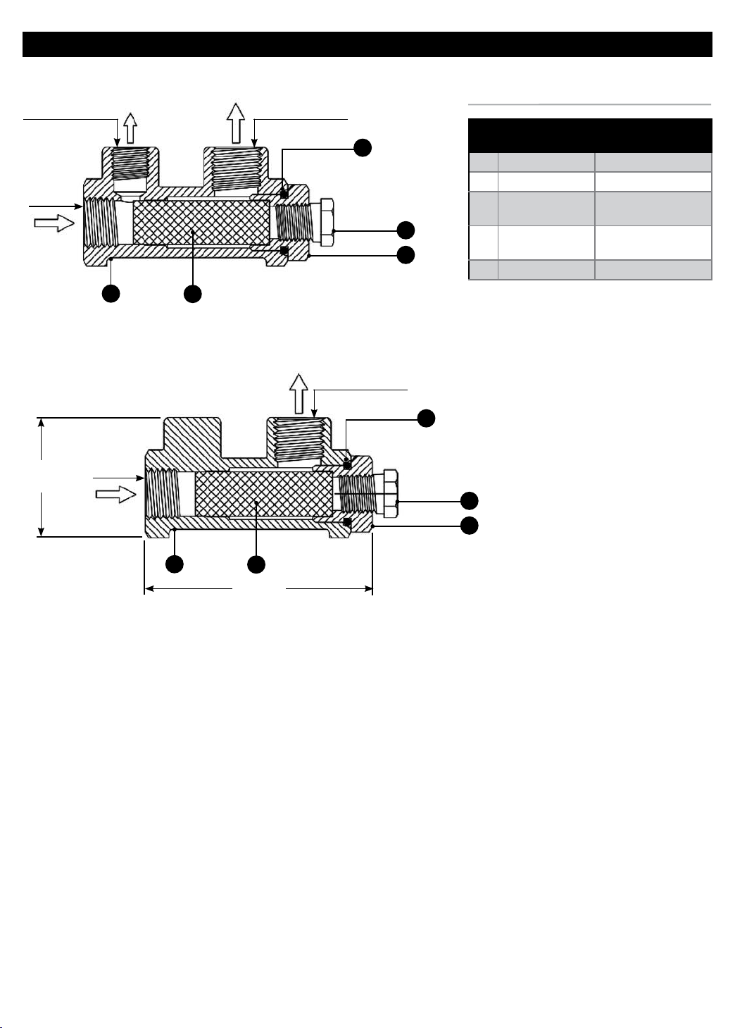
Strainer – Parts & Dimensions
1/4" NPT
3/8" NPT
Flow In
1- 9/16"
(40 mm)
Sensing or Gauge
Connection
1
Model J0097A
3/8" NPT
Flow In
3
Flow Out
3/8" NPT
Flow Out
4
3/8" NPT
PARTS LIST
ID DESCRIPTION MATERIAL
1 Body Stainless Steel 316
2 Screen Retainer Stainless Steel 316
Screen (40
3
5
4
2
5 Blow Down Plug Stainless Steel 316
Mesh)
Screen Retainer
Seal
4
5
2
Stainless Steel 316
Buna-N
1
3
3" (76 mm)
Model J0098A
11
Page 12

MUELLER® | ECHOLOGICS® | HYDRO GATE® | HYDRO-GUARD® | HYMAX® | JONES® | KRAUSZ® | MI.NET® | MILLIKEN® | PRATT® | SINGER® | U.S. PIPE VALVE AND HYDRANT
833.367.6835 – www.singervalve.com – [email protected]
INTERNATIONAL – 1.423.490.9555 – www.mueller-international.com – [email protected]
Mueller refers to one or more of Mueller Water Products, Inc. a Delaware corporation (“MWP”), and its subsidiaries. MWP and each of its
subsidiaries are legally separate and independent entities when providing products and services. MWP does not provide products or services to
third parties. MWP and each of its subsidiaries are liable only for their own acts and omissions and not those of each other. MWP brands include
Mueller®, Echologics®, Hydro Gate®, Hydro-Guard®, HYMAX®, Jones®, Krausz®, Mi.Net®, Milliken®, Pratt®, Singer®, and U.S. Pipe Valve & Hydrant.
Please see muellerwp.com/brands and krauszusa.com to learn more.
Copyright © 2019 Mueller SV, Ltd. All Rights Reserved. The trademarks, logos and service marks displayed in this document are the property of Mueller Water Products, Inc., its afliates or other
third parties. Products marked with a section symbol (§) are subject to patents or patent applications. For details, visit www.mwppat.com. These products are intended for use in potable water
applications. Please contact your Mueller Sales or Customer Service Representative concerning any other application(s).
12
 Loading...