

Page 1
18131)
INSTRUCTIONS
FOR USING
THE SINGER PORTABLE
ELECTRIC SEWING MACHINE
No. 99-13
(ATTACI liVlliN 13 I ¿0360)
WITH KNEE CONTROL
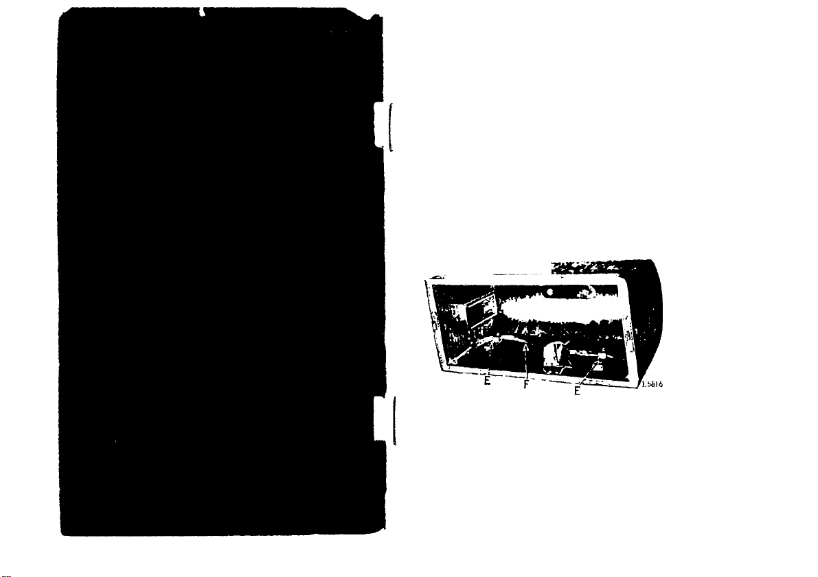
Fia. 1. KnKH I.kIVER IÍÍ PuRlTION IN CoVKU
AfUir miioviiiK llie cover, remove (he knee lever
(F, Fig. 1) from (he two cleats (K, Fig. 1).
NEVER USE OIL ANYWHERE ON THE MOTOR —
Lubricate only with Singer Motor Lubricant and use it
only in the two grease tubes provided for that purpose,
Page 2
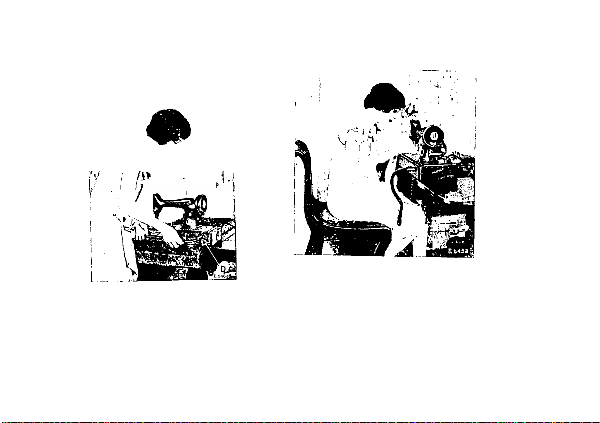
To Adjust the Knee Lever
Ilokl Uio lever iii the hurizoïilal position as sliown
in h'ig. 2, and push the soeket of the lever over
Fia. 2. Pl.\cing Knee Lever in l’osmoN
the stud (n, Fig. 2). Allow the lever to dnip
into the vertie.al i)Osilion as shown in Fig. 2, page 2.
Fiü. 3. Knee Lever in Position Heady
FOU ül'ERATIÜN
Page 3
Motor can be Operated on Either Alternating
Current or Direct Current
The ctccli'ii! iiiulor, which is located at the. liaclc
of Ihu machine, can he opcrateil on oil her altcniating emrent or direct enrrent, as desiiv<l. 'riie
slnndard windiiigs of tlio motor are for ill) volts,
and motors can he fnrnislicd tor any voltage hetweon
100 and 250.
¡Special motors for 32 volts direct current, and
for 50 volts alternating enrrent and direct cuiTont,
have also hcen developed ami aie availahle.
Points to Determine before Connecting
Motor to Electric Service Line
Obtain the following information from the Elec
tric Light ftompany which supplies the electric
current for the circuit to w'hich the mohir is to
he connected:
1. AN'hat is the voltage? 'I'he voltage must he
within the range stamped on the motor nameplate.
2. If the current is alternating, what is the num-
her of cycles? 'I'he mimher of cycles must he
within the range stamped on the motor name plate.
The voltage of any circuit and, if alternating
current, the number of cycles, can he verified by
looking at the name plate on service watt meter
installed by the local Electric Light Company.
To Make the Electrical Connection
Enwind the. electric cord, screw the plug at the
cnil into an electric light socket and turn on the
switch.
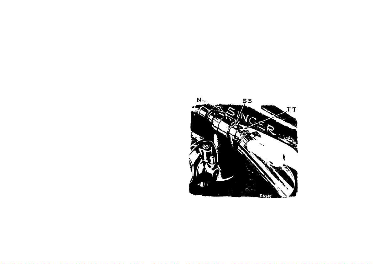
To Turn Singerlight “On” or “Off”
lieach over the toji of the machine and move
the switch lever (N, Eig. -Ij to the right or left a.s
tlcsil'dll.
4
Page 4
6
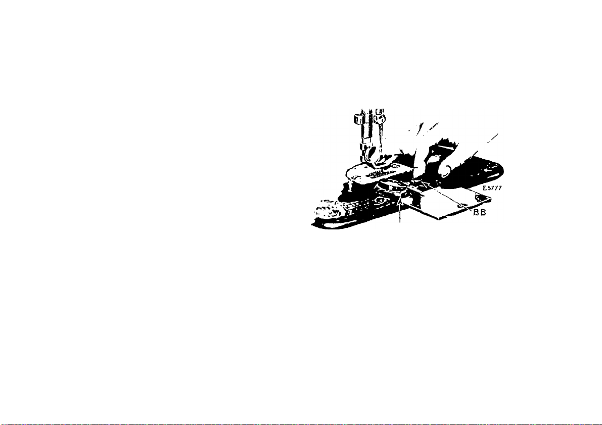
To Remove and Replace the Bulb
To remove the hull), hold the Biogerlight socket
tighllj' with one hand and with the other hand
turn I he shade halfway around until the pin tBB,
hig. ll for the shade is in the slot of the shaile, then
gently slip the shade olT and allow it to hung free as
shown in Kig. -1.
Do not attemi)t to unscrew the hiilh. It is of
the hayonet and socket type and does not unscrew.
1‘ress the hull) into the socket anil at the same
time turn it until the hull) i>in 1'1’T, Kig. 4) is out
of the notch in the socket, then withdraw the
hull) and shade.
To insert a new hull), pass the hull) through the
collar of the shade with the slot of the shade up
ward. Hold the socket tightly with one hand and
at the same time with the other hand pre.ss the
l)ulh into the socket with the hull) i)in (TT, kig.
4) in the slot and turn it until this pin is in the
notch. 'I'lien slip the shade over the socket, the pin
tS.S, I’ig. 4) for the shade entering the slot of the
shade. See that the pin (SSJ is in the groove of
the shade and turn the shade halfway around, or
until it is at the top.
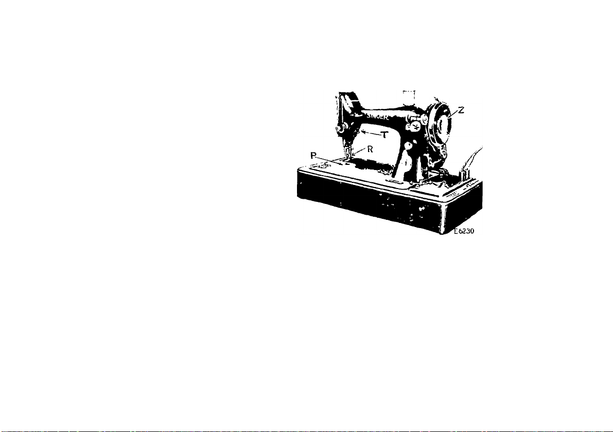
To Operate the Machine
'J’o prevent injury to the presser foot (R, Tig. 5)
and feed (P, Tig. .5), raise the presser foot (R)
hy means of the presser bar lifter (T, ]'’ig. 5).
Us
0. Tuont Vitiw ui«* TUB Macuinu
PlilCU a piece of cloth under the presser foot
and then let the foot down upon it.
Turn on the electric current and lightly press the
knee lever to the right. As you press haidcr against
the knee lever, the speed of the machine is increa.seil,
(he speed being eonirollcd entirely by the degree to
which the knee lever is pushed over. Operate the
machine in this way witliout being threaded, until
you have become accustomed to guiding the ma
terial anil operating the knee lever.
Page 5
To Ensure Perfect Action of the Machine
'I'lic Inilillice wheel iiniisl always turn over towaril
yon.
Do not rnii the luaelhno with the presser foot
resting on the Cecil without cloth nniler the jnesser
toot.
Do not run the niaehine when both bobbin ease
anil neeillo are Ihreaileil unless there is lualerial
umler the [ire.s.ser toot.
Do not try to help the jnaehine by [Killing the
fabric lest you bend Ihe needle. 'I’he inaehine feeds
the work without assistauee.
The slide over the bobbin ease should be kept
elo.sed when the inaehine is in o|)eration.
CAUTION
When through with your sewing, always
turn off the electric switch at the lamp socket.
To Take Out the Bobbin
Draw to the left the slide in the bed of the
inaehine and [iress the forelinger of the right hand
A A
To Pack Up the Outfit
Heniove the [ilng from the electric light socket
and coil the electric cord around the uiachine.
liaise the knee lever to a liorinontal position, re
move it and replace it into the cleats (li, Kig. 1,
page 1) in the cover, lleplace the cover and lock it.
Fio. 5. Tiiif: Boudin
u|ion the bobbin ejector (Bli, Pig. (>); this will
rai.se the bobbin so that it can be easily taken out.
Page 6
10
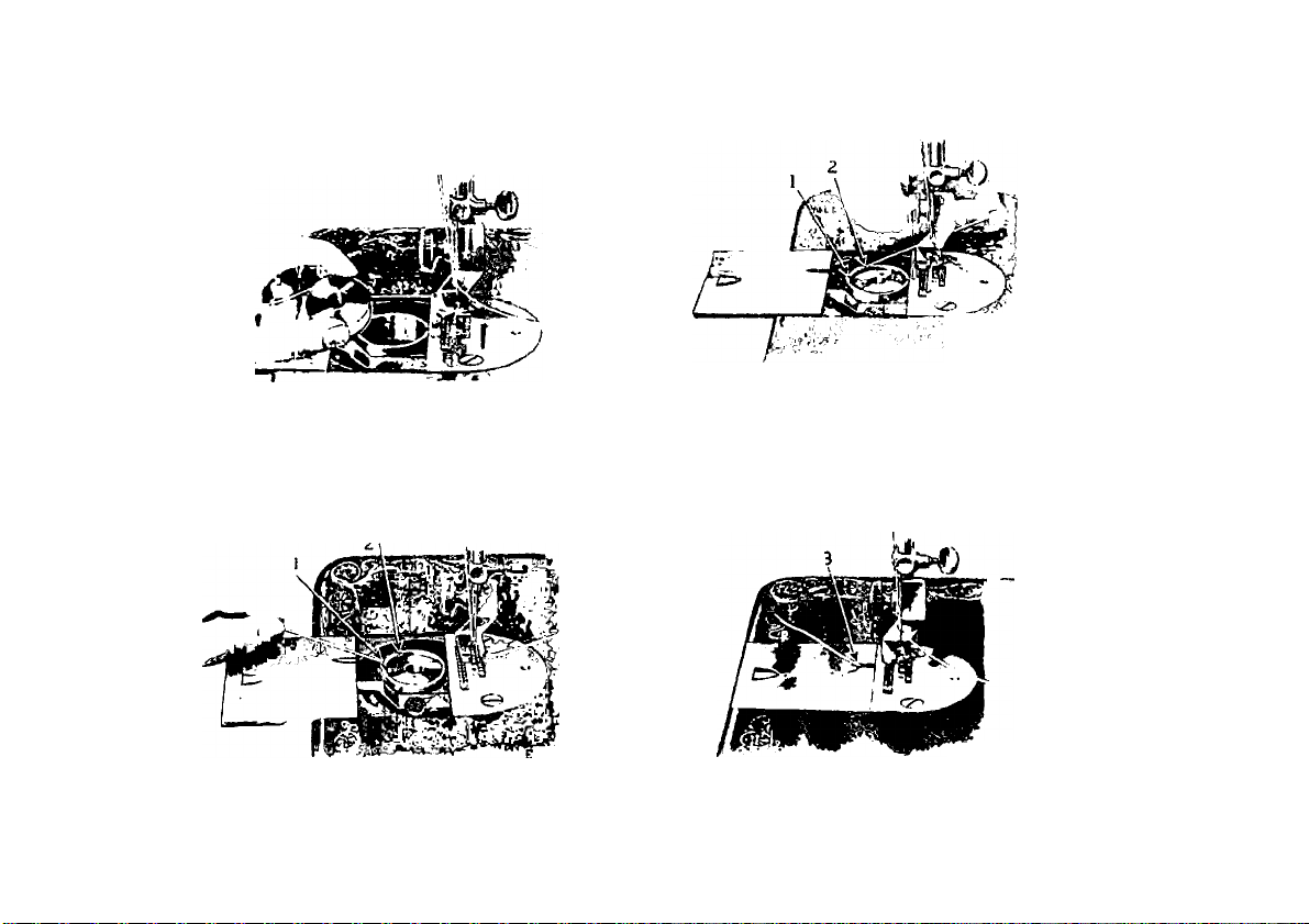
To Wind the Bobbin
lb iri iicec.ssiiU'y bo undiM’sliMul ilio slop iuol.i«)n
C/j, l’’ig. 5, pagò 7) by wliioh Lhu balaiioc wheel
11
7) then np into the lower eyelet (3, Fig. 8) of the
hobbin winder thread guide, into the notch (1, F'ig.
£5780
Flo. S, \Vr^fJ>l^ao TUB liouui.v
E»-05
MACiiiNe 'l'uite.vuKU euu WiNeise 'niK Uüuuik
(U, Fig. 5) ean l)e reloiised when leituired, bhus
peniiil.tiiig the winding of bobbiits wilhout. iiminng
llie slilehing meehanisin. It also allows yon
to wind bobbins wilhonb removing parlially sewn
work and wilhont nnthreading the machine.
To I'elease the balance wheel (U, Fig. 5), turn the
stop motion screw ('/, Fig. 5) over toward yon.
IL is iiocossury to hold the bulanco wiieol >viulc
ooscning me SLop nioiiou ai.iv.«.
loosening the stop inoLiou screw.
I Unte the bobbin on the bobbin winder spindle
(V'V I'ig. S, page 11) and push it up closely against
the shoulder, liaving the small jiin in llie spindle
enter the hole in the side of the hobbin. Fnt the
spool of thread on the spool |im (1, Fig. 7). I ass
the end of the thread into the thread guide (2, Fig.
8) ami piuss the tlinuid Ihrongii tlu* link; in tliL* loftside of the liobbin (5, Fig. 8), from the inside. I’re.ss
I he bobhin winder pulley (J.I, Fig. 8) tiown on the
halunee wheel hiih, and the latch (1111, l-'ig. 8) will
drop down and hohl it. 'I'lien start the lialanee
wheel in motion the same as for sewing.
The end of the thread niiist he held hy the hand
until a few coils are woimd and should then he
hioken oil. When siiilieient thread lues lu'en woiiinl
upon the bobhin, the bobbin winder is antomatieally
reloxsed from tlio balance wheel.
Jf the pressiiie of the rubber ring (,U, l-’ig. 8)
agaiiisl tile hub of the balance wheel is insullieienl
for winding the bobbin, loosen the adjusting screw
(GG, Fig. S) and [iress the bohhin wiiuler lightly
until the rnhher ring is in contact with the hub of
the balance wheel; then tighten the screw.
i
Page 7
13
To Replace the Bobbin
Ilukl the bobbin between the thuinl) ami fovclinger of I he left hand, tlie Uneail leacling on top
fi-oni the rijilit lowaiil the left, as shown in Fig. 9.
FlU. 1). UE1M..»C1.S'U the tiOUUIN
I’laee the bobbin into the bobl)in emse and draw
the thread into the slot (1, Fig. 10; in t-l'n bobbin
ease, as .sliown below.
i;s
Oraw the thread backward between the bobbin
case ami the tension siiring until it reaches the
l*u:. H. BoGiiiji Case n*mtBAUED
notch (2, Fig. 11) then pnll thè thread toward thè
righi, as shown in Fig. 11.
W'hcn clo.sing thè slide, see that thè thread is in
thè slot (3, Fig. 12) in thè right edge of (he slide, as
.shown below,
Fig. io. Tuiie.i.oiNa tue Bouuis Case
nao
nsr.*
Fu;. 12. UndEIC TuUEAUlNO Co.Ml'LE'rKI)
Page 8
1-1
To Set the Needle
'I'uni Uic bivlmuio wliocl ovei' loward you until Iho
iiooillo l):u‘ moves u|) l.o ils lushest point, loosen
tin! (liiiinb screw (ICIi, I’ig. 7, page 10) in the nceille
cliimp (1)1), Fig. 7), limi put tin: iioeillo up into
the clamp as fiir ¡is it will go, with ils Hat side
towaiil the right, then tighten the thumb .screw.
To select the eorieet needle see page 4cS.
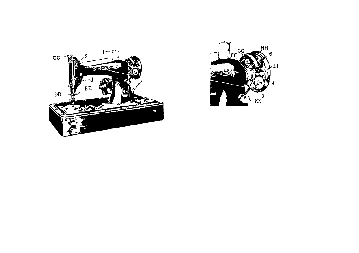
To Thread the Needle
See l‘'i*i. IS ON TUB Foi.lo\vjno Paob
Turn the balance wheel over towaid you until the
thread take-up lever {,5) is rai.sed to its highest
])oint. 1‘laee the spool of threail on the spool pin
at the top of the Jiiachine, lead the thread into the
Ihread guide (1) at the left, down, uiulcr and from
right to left between the tension discs (2), into the
small wire siiring (3), under the t.hrcail regulator (-1.)
at the left (not through the eye in the thread
regulator), up innl from right to left through the
hole in the end of the thread take-up lever (5), tlown
into the eyelet (ti), into the lower wire guide (7),
then from left to right through the eye of the
neeille (8).
Diaw about two inches of thread through the
eye of the jicedle with which to commence sewing.
Instructions for threading the machine for darning
and for embroidery are given on pages 41) and 47.
15
, Eó-HS
i'lij. 13. TiiJtK.1
.VDZN<} TUB
Page 9

1(5
To Prepare for Sewing
Have tlic lake-iip lever at, its liigliest point, llieii
wilh the left haml hold the end of the needle
tliread, leaving it slack from the hand to the neeille.
Fio. U. Duawinu Up tub Bouuin Tukeau
'rum the halanee wheel over towanl you until the
needle moves down and up again to its highest point,
thus catching the bohinn thread; draw up the needle
thrtaul aui.1 the bobbin threatl will come up with it
through the hole in the throat plate (.see I'ig. 1-1).
Lay both threads back under the presser fool.
To Commence Sewing
Place the material beneath the presser foot, lower
the presser foot and commence to sew', prejising the
knee lever to the right to start the machine.
17
To Remove the Work
Let the thread take-up lever rest at its highest
point, rai.se the pie.s.ser foot and draw the fabric back
ami to the left, p,a.ss the threads over the Ihreail
cutter (tj, Pig. 14, page 10) and pull dow'ii lightly to
sever them. Leave the ends of the Ihreail under
the i)ie.s.si'r fool.
Tensions
Por ordinary stitching, the needle and bol.biu
threads should be locked in the. centre of the thickness of the nmicriill, thus:
Fuj. 1;">. 1*KKKKL'T SiTivH
if the tension on l iio neetlle tln-eiul is too tight, or
if that on the bolihin limiacl is too loose, the neetlle
thieail will lie sliaight ahmg the upper surface of
the material, thus:
Fig. 10. 'I'lGiiT NcifOLh: Tension
If the Icitsion on the l>ol>I)iu thi'catl is too tight, or
if that on Iho needle thread is too loosci, the bobbin
thread will lie straight along the under side of the
inatorial, thus:
Fiu. 17. Luosu NKEULk: Tuue.\d Tension
Page 10

IS
To Regulate the Tensions
7'/i(i iensian on llio nced'ii Ihraid altoidd oidy ho
rajtdaled u'hoi llio /j/cssir fool is dtnon. Iliwiiii;
I’lG. IS. NsiiiK.ffl TmiEAO Te.msion
Idw uioiI Hie presaur luol, tuia Ilio simili llimuli aal.
(.1, sliowii ill I'ig. 18, above, and l'’Ì!5. 7, pago IO) al
Ilio frolli of Ilio LiMisiou discs over lo Ilio ri.gliL lo
iiicrcaso Ilio loiisioii. To doiaeaso Ilio toasion, turn
ibis lliiitiib mit ovor lo tho lofi.
Tlio lonsioii OH die bobbin lliioad is legiilaled by
die larger sorow fA.V, Tig. (i, |>ago !)) wliirli is
nearosl Ilio back in Ihe bobbin case lonsion spring.
To inoroase Ilio lonsion. Im a ibis sorow over loward
you. To deoroase Ilio leusion, turn lliis sorow over
from you.
Wlion the lonsion on Ilio bobbin Uiroad lias boon
ouoo pro[iorly adjn.sl.oil, il is soldoni nooo.ssary to
oliungo il, as a oorrooL sliU ll oaii usually bo obtainod
by varying die lonsion on Ilio noodle Ibroail.
To Turn a Corner
»Stop die inaoliino when the noodle is oouinionoing
its upwaril stroke. Kaiso die pressor fool and lur
die work as desired, using die noodle as a pivo'
(lion lower die pro.ssof fool.
19
To Regulate the Length of Stitch
The loiigdi of stiloli is regulated by (ho large
diunib sorow (KK, Fig. 8, page 11) at the front of
the niaeliino near llio bobbin winder.
To leiigdion die stiloli, turn lids tliiinib sorow
ovor lo die right. 'I'o shorton the stitoh, turn this
thumb .sorow ovor lo tho lofl.
To Regulate the Pressure on the Material
For ordinary family .sewing it is seldom nooos.sary
to oliaiigo the prossuro on llio material. If sowing
lino silk or lliiiisy inalorial, liglilen the prossuro by
turning tho dunnb sorow (C(t, Fig. 7, page 10) on
die lop of dio maohiiio ovor to Iho lofl. To inoroaso
the prossuro, turn this Ihunib sorow ovor lo the rigid,
d'lio pressure should be only heavy enough lo
lirevont the inalorial from ri.sing with tho noodle
and lo enable llio food to move the work along
evenly; a heavier prossuro will make tho inaehine
run hard.
To Sew Flannel or Bias Seams
Vise a.short slileh and as light a lonsion as iiossiblo
on the noodle throad so as lo leave the thread loose,
enough in the seam to allow the goods lo strololi if
noecssary.
A Stitch to Ravel Easily
can bo made if desiirod, by having the tension
on llio noodle thread so light (hat the bobbin thread
will not draw into the goods but lie straight, as
she rii in Fig. 17, page 17.
Page 11

20
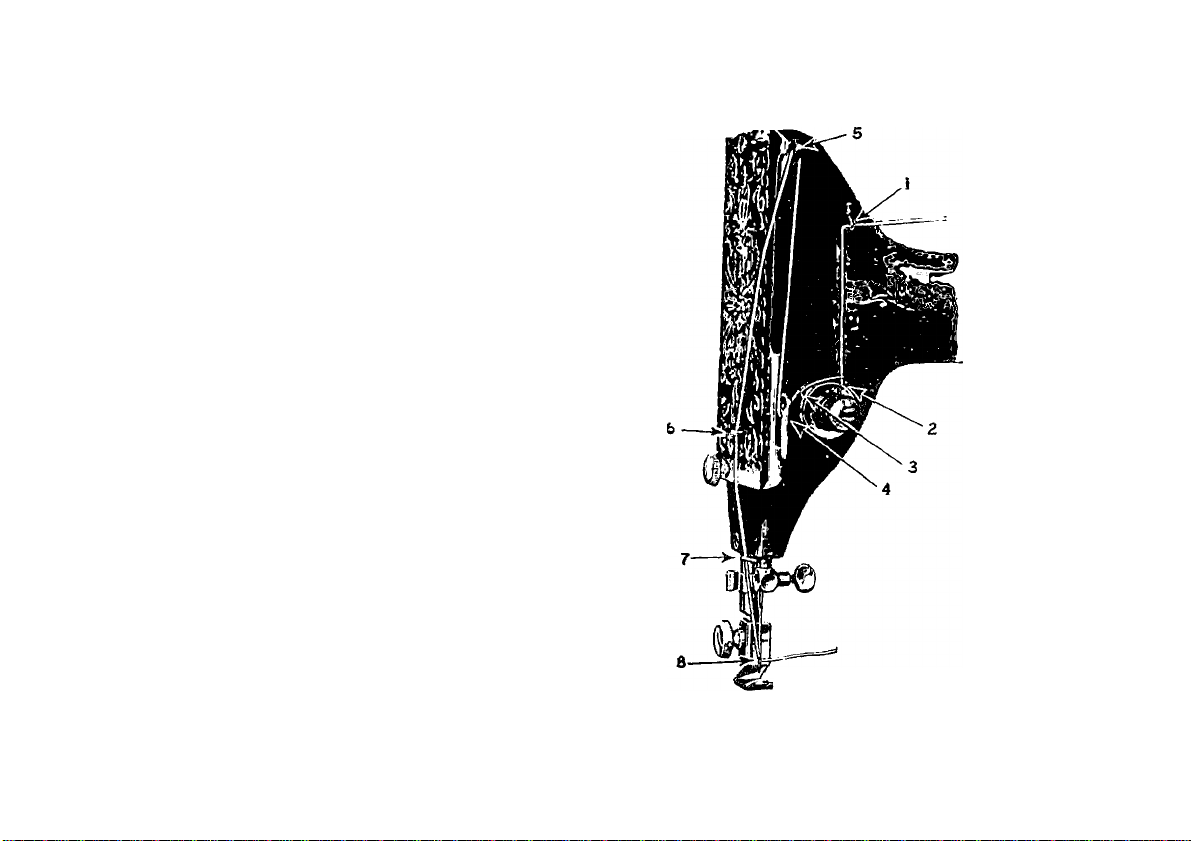
To Oil the Machine
'I'd eiisui'o easy running, Llin inacliine rciiuiius
oiling, anil if usotl conLinuuusly it sliuulil bu oilud
21
To oil the movable parts in the head of the ma
chine, lake out Ihe thumb screw (VV, Kig. 10) near
E62J1
Fw. 19. Fkont View, Saowi-sc Oiling Points
each day. Willi moderati; use an occasional oiling
is suilicient. Oil should hu applied at each of Iho
places .shown by arrows in Kigs. 10 and 2!1. Om;
drop of oil at each point is snllicieut. Oil lioles
are provided in Iho inaehino for bearings which
cannot bo ilireetly reached.
To oil (he mechanisni under the slide, draw Iho
slide isee big. 10) to the left and after removing the.
lint and dust which may have accumulated (see
instruclions on [lages 23 to 2(i, inclusive), i>ut a
few drops of oil on the small piece of felt at the
right of the bobbin ejector. 'I'hc slide should then
be closed.
Pig, :ii). Oiling Points in li.isE üc M.icjiine
the lower end of the face |ilate and loosen the screw
(Idi, big. 19) near the upper end of the face |)late,
then sli]> the face )>late down; put one ilrop of oil
into each of the oil holes and joints thus uneovered,
then replace Ihe face piale and fiusten it as before.
To reach the parts underneath the bed of the
machine, turn the machine back on its hinges and
apiily oil to the oil holes and bearings indicated
by the arrows in h'ig. 20.
Page 12

■23
To Lubricate the Motor
iS’KVWK USK Oth ANYWTIlOlilO ON ТИК
МОЧ’ОИ. W lii-u the niatliiiie ia alii|)[)(;(l from the
Fic. Morou Окалае Tuues
factory, tlio two motor greaae tuhea (GO, Fig.
■Jl) are tilled with aufliiient hihricaut for appro.xiouilely aix moiiLhs’ use, under ordinary eircum-
staiieea.
At loaat once every si.x moulha thereafter, these
greaae tnhea ahoiild Ije relilled with tlie Singer
htolor l.nhrieunt, fnrniahed with the machine. 'Го
do (his, insert the li)) of the tube of lubricant into
the hole at the top of each of the grease tubes
and force the lubricant through each hole until
lioth grease lubes are lilled.
To Clean the Stitch Forming Mechanism
.After conaiilerable use, the stitch forming mechan
ism may become clogged with lint and this may
interfere with the perfect operation of the machine.
Occasionally remove the l)obbin case from the
machine, as instructed below and on the following
page, ainl remove any lint, etc., which has accumu
lated in the machine.
To Remove the Bobbin Case
{Oi-KnAion bei.NU .vr the i'lto.sT or tue Млсшпе)
liaise the needle to il.s highest point by turning
the balance wheel over tou'aril j'ou. IDiaw the
slide plate (Л1М, Fig. 22) slightly to the left, tlien
lift its right hand eiul and ilraw i t toward the neeille
until it is disengaged from the spring in the beil of
the machine.
FtC. 22. SlIDEltEMOVED
Page 13

24
To Replace the Bobbin Case
(OesuATOu BeiNC at tub Fuont or the Machine)
See that the neeille is raised to its highest point
and that the latch (N N, I' ig. 25) is raised from the
slot (UO, J'’ig. 25) and moved toward yon.
Insei't the nail of the forefiiiger of tlie left- liaiul
imdcr llic latch (.NN, Fig. laiso the lalch just
high ciumgh to cliau' the edge at (00, Fig. 211)
and then move it toward you.
Under no circumstances must the screw (PP,
Fig. 23) be loosened. 'I'ho loosening of this screw
will change the clearance for the thread between the
I'lo. Raisinu tub Latch
bobbin case and bobbin case position bracket.
Hold the bobbin ca.se between the forefinger and
the thumb of the left hand as shown in Fig. 21. Tilt
the bobbin case to the left and at the same time
slighlly turn the right or forked end toward you
so that it is moved out of engagement with the
sewing hook. Then tilt the bobbin case toward
the right and remove it (See Fig. 21).
I'lu. 21. Rbmovisg tuu Boubin Case:
Fio. 25. SaowiNO the Bobbin Case
Position Bbacket
Hold the bobbin ca.se between the forefinger and
thumb of (he left hand, a.s shown in Fig. 21. Insert
the forked end of the bobbin case under the throat
[dale so that the fork straddles the end of the
bobbin case iiosition bracket ((¿(¿, Fig. 25). Then
with a slight twisting motion of the bobbin case
to the left and to the back, lightly press it downwanlly until the edge of the sewing hook engages
in the groove under the rim of the bobbin case.
Page 14

2(5
Huviiig set Uic liulibiii ca.se into the correct
position, lock tlie lat(-h (XN, Fi^^ -Jo) in tho notch
(00, i'ig. 25) to hold the boLiljin case in place.
Fio. 26. Iii3PL.\ciN« TUB Sua-o
Thou replace the slide from the right, iis shown
in Fig. 2li, being careful to see that tho two cmls
of tho spring ( K li. Fig. 2(5) enter the grooves on the
uinUaside of the slide.
27
HINTS
Machine Working Heavily. If tho nuichine
runs hard after standing itilo for some time use a
little kerosene in the oiling places, run the machine
rapidlj', then wipe clean anil oil.
To Avoid Breaking Needles. See that tho
pressor foot or attachments are .seimroly fastened by
tho llunnb screw. Do not sew heavy seams or very
thick goods with loo lino a needle. A large needle
and thread lo corresponil .should be lused on heavy
work (.SCO Jingo 18).
See that (he needle is not bent and avoid jmlling
tho material when stitching.
Breaking of Needle Thread. If tho niasllo
thread breaks it may be caused by:
Improjier threading.
'I'ension being too tight.
Needle too lino for size of l.hroail.
I'he thread being too coarse for size of needle.
The needle being bent, having a blunt jioint,
or being .set incorrectly.
Breaking of Bobbin Thread. If the bobbin
thread bi’caks it may be caused by:
Improper threading of bobbin ease.
Tension being too tight.
Skipping of Stitches. 'I'ho needle may not be
..ecurately sot into tho ne.edle bar or tho needle may
■'unt or bent. 'I'lie needle may be too small for
•ead being used.
Page 15

INSTRUCTIONS
FOR USING
ATTACHMENTS
120360
WITH
SINGER SEWING MACHINE
No. 99-13
Page 16

31
FOOT HEMMER—Hemming
Raise the needle to its liighest point. Remove
llie piesser foot, ami attach the foot heimner in its
Imu. 27
phu;e (see Fig. 37). Olip olT the right hand corner
of the cloth, so that it will take the roll easily, turn
np the edge ahont a. (luarter of an inch, insert it in
tlie month of the heinmer and draw or push it along
until under the needle. Then let down the presser
bar ami after taking two or three stitches, draw
gently on the ends of the threiuls to help the work
along till the feeil catches it. In order to produce
a .smooth even hem, the month of the hemmer must
be kept just fell.
Fig. 27 shows also what is known as a bag seam
o" fell, iniule by pmssing two pieces of fabric through
he hemmer together and hemming them dowi|
Page 17

32
FOOT HEMMER—Hemming and Sewing
on Lace
Slart Ilio hem us jnevioiisly ex|)Iuiiicil, uml wlioa
it is well stili teli, raise the needle to its highest imint.
1‘’ш. 2S
Kaise the heiiimer to relieve its pressure on the hem,
puss the end of the luce through the slot in the side
of the heinmer, under the haek of the heumier and
over the hem, as shown in Fig. 23.
'Гаке eare that the hem is not displaced in the
heminer and that the needle goes down through the
lace anil hem together. 'I'lien let down the pressor
bar and guide the lace over the front of the hemmor,
keeiiiug it well into the slot.
FOOT HEMMER—Felling
'I'he two pieces of cloth to be felled should be laid
one over the other, right sides together, the edge
of the under piece being a little farther to the right
than the upper jiiece. Stitch them together, using
the heinmer as a [iresser foot, the front eni! of the
33
heminer forming a guide for the edges of both (lieces,
the upper piece being guided by the inside anil the
Fra. 29
under piece by the ouUide of the ])rojeeting front of
the foot hemiiier (.see Fig. 20j. Then open the work
li'ra. 30
out Hat, wrong side up, the edges standing up
straight, and taking the edges near the beginning of
Page 18

34
Ilio soam in Uic riglit liaiul, and tlie ends of llie
llireads in Un; loft haiul, iliaw l.l;u edges inl.o (lie
lieinmer whieli will Liini tliein as in heinniing. ( iuide
llie seeond l'ow of s(,il.eliiiig liy following (.lie lirst
row will; the inside of the projecting front of the
foot hennner (see h’ig. 30, page 33).
ADJUSTABLE HEMMER—Hemming
Ueinove the pros.ser foot and attach the adjustahle
heminer in its place as shown in I’ig. 31. This
E etili i
Fiu. at
hcininer will tura hems froin indi lo 1 indi wido.
The adjnslnient is made liy ìooscning thè thniiih
screw Oli thè heminer and laoving thè slide to (ho
right or loft iinlil Ilio hcm tiirned is of thè dcsircd
widlh. Entcr thè edge of thè eloth inio (he heiiiiner
under thè scale and drinv it laick and forili nntil
thè heni is forincd, stopping with (he end uinler thè
iieedle. l.owcr thè pre.sser bar and eomnicnco to sew,
heing carefid to so guide eloth as lo kecp heinincr
full. Felling cali ulso ho done wilh thè adjuslahlo
heinnier hy following instriictions oii page 3’J.
35
ADJUSTABLE HEMMER—Wide Hemming
To make ahem more than one inch wide, take out
the thuiiib screw in the heminer and remove the
r'l.:, 32
sliile and ijointer; fohl and erea.se down a hem of the
desired widlh; pass the fold under the e.'iteiisiou at
the right of the henuncr and the euge into the
folder as shown in Eij;. 3'2 and iiroeeed to stitch the
hem.
BINDER—Binding
Ueinove the presser foot and attach the hinder in
its place. Pass the hinding Ihroiigh the scroll of
I he hinder and draw it hack under the needle.
Place the etlge of the goods to he hound hetwcen
the .scrolls of the hinder and draw it under the needle,
liower the pre.sser har ami sew ns usual. T'o make
Ereiich folds (iroceed as directed for hinding e.scept
I’ at the fold is stitched on to the face of the material
Page 19

ilo
iilslcuil i)f oM tliu (st:e l’’ig. AfUir loosfiiiiig
thè biiuler set sci'iiW iiiid luljusting thè hiiiikT, (i e
37
Having ailjiisted the scales for tuck and space as
desired, fold the material anil crease by hand; iiass
kiu. 33
line of sl.itehiiig eoa he brought nearor the centre,
this being lume elTcclive when making 1''rendi fiiMs.
TUCKER
Keaiove the presser foot and attadi the tucker
ia its place. 'I'he width of tlie tuck is detcraiiacd
by the .scale of figures acaicst the needle, which
shows ia eighths and sixteeatlis of aa inch the dis
tance of the edge of the fold from the line of stitching.
'I’lie crea.se or mark for the second and following
tucks is determined by the .scale nearest the operatin'
and this is set by the line in front of the needle hole
in the presser foot. l'‘or blind tucks without spaces
set both .scales at the same figure; to make spaces
bciw.'ea the tucks, move the front scale farther to
the. left until the ilcsired space is obtained.
Fiu. 31
the folded edge between the spring and spur near
you, then between the two blades of the second
scale, and back under the presser foot; draw to the
right against the guide, lower the presser bar; see
that the lever for the nceille clamp to strike is in its
backward position so as to form a crease for the
ne.\t tuck, then i>roceed with the liist tuck.
For the second tuck, fohl carefully at the crease
made by l.he spur and place the edge of the lir.st tuck
inulerneatli .mil against the spur at the left, 'fhe
spur will serve as a guide and will also make a
distinct crease for the next tuck. .Always place the
last tuck against the spur to ensure perfect woi k.
When making the last tuck, the lever upon which
the needle clamp strikes while tucking .should be
raised to its highest point; while the lever is m this
po.silion no crease for a succeeding tuck is made
upon the goods.
Page 20

38
Rüffler
Lines 1, 2, 3, -1 and 5 slniwii in Kij{. 35 indieate
wliori! fill! iiiaUrial is to lie, planed for Various
o()erafioiis, as follows:
8
14 13 E 5152
Fiu. 35. Tue UuFt'i.tac .v.\ii u's F.vkts
Line 1—the correct po.silion for llie inalerial to
which the. riillled material js aiiplied.
Line 2—material to he (iatheroil.
Line 3—ihe facing for the rullle.
Line 4- the strip of piping material.
Line 5—the edge to be piped.
Refer to h'ig. 35 when inserting the material in
the miller.
3'J
The names and u.ses of the principal parts of the
Inltler are as follows:
(Hkis: N4>ü. tN So)
6— Foot—the part by which the rnHler is atliudied
to the presser liar.
7— Fork Arm—Ihe section that must he placed
aslrido the needle clamp.
8— Adjusting Screw the screw that regulates
the fullness of the gather.
9— Projection—the. part that projects throngli the
.slots in the adjnsling lever.
10— Adjusting Lever—the lever that Sets the
miller for plain gathering nr plaiting.
11— Heading Guide— guide for the heading of the
rnllle.
12— Separator Plate—tlie gniile on the mulerside
of the miller, containing several .slots inlo
which the edge of the inalerial is slipped to
keep the heading of the rullle even.
13 Ruffling Blade—the upper hlne steel bhule
with teeth at the end to posh the inalerial in
plails up to the needle.
14—Separator Blade —the lower blue steel lilude
without teeth, which inevenls the teeth of
the milling blade eoming into contact with
the teeth of the feed ihig.
To Attach the Ruffler to the Machine
Raise the needle liar to its highest point and relunve the pre.s.ser foot. Attach the miller foot to the
lire.sser bar by means of the thumb screw, at the
same time placing the fork-arm astride the needle
clamp as shown in Fig. 3li.
Page 21

40
To Adjust the Ruffler for Plain Gathering
liaise llic ailjiisliiij; lever (10, Fig. SOj luul move it
to (lie left so that tlio projeetioii (0, Fig. 3liJ will
enter (lie slot marked “1” in the ailjiisling lever (101
when (he lever i.s released. 'I'he milling blaile will
then move forward and baek onec at every stiteh.
liKsert the material to be riilHed between the two
blue blades, following the line 2 in Fig. Ik'S. Draw
the material slightly baek of the needle, lower the
pres.ser bar and <a)mmenee to sew.
To make a liner gather, shorlen the stroke of
the ruining blade by turning the adjusting screw
(8. Fig. 30) up, also shorten the stiteh. To make
a fidler gather, lengthen the stroke of the ruilling
blade by turning the adjusting screw (S) down,
also lengthen the stitch. By varying these a<ljustments many pleasing varietie.s of work can be
accomplished.
■11
To Make a Ruffle and Sew it to a
Garment in One Operation
Insert the material to be milled between the two
blue blades, its shown in F'ig. 37, following tlie line
1' lo. S7
2, in Fig. Place the garment to which the
rulllo is to be attached, under the. separator blade,
following the line 1, in F'ig. 3.5. Procecrl the same
as for |>lain gathering.
The edge of the milled seam can be bound by
n.sing the biiuler as instructed on (lages 35 ami 3li,
To Ruffle and Sew on a Facing
in One Operation
Insei t the material to be. milled between the two
hlne blade.s, following the line 2, in Fig. 35. I'lacc!
the gaiinent to which the rullle is to be al.tatrhed,
miller the separator blade, following the line i, in
Fig. 35. Place the material for the facing over the
upiier blue blade, as .shown in Fig. 3S, following
the line 3, in F'ig. 35. The facing may be straight
or Idas material. If the facing is to be on the
right side of the garment, place the garment and
Page 22

42
Uu) millo so Ilio wioiijí s¡(li\s aro tojíotlior. If
tilo faoiiii: is lo 1)0 Oll Ilio wrong si.lo, placo ilio right
sillos of the gaiMiwnt ami the vulHe togolhor.
Kuj.
Piping a Ruffle
Insert Ihc rnatorial lo ho riilHod hotwoon the two
hliio hiailos, following the line 2, in l'’ig. 35. 'I’liis
malorial must not he over 114 inches wide, a-s
it is carried through tho rnlllor with the linished
•43
edgo of tho rullio lo thè right of Lho altachnienb
ius shovvn in Kig. 3!).
Tho inatorial for piping must inoiusuro ahout },(
indi wido \idicn foldod in tho contro and is usually
cut oli tho hia.s. I lai'O tho liiping inatcrial in tho
rulllcr, following tho lino -1, in Kig. 35, with tho
foldod edgo of Ilio piping lo Ilio riglit. 'l’Ilo mate
rial to which tho piping ami riillliiig aro lohosown
shoiiltl ho foldod oii (ho edgo and iiisortod in tho
rulllcr, following tho lino 5, in Kig. 35.
To Adjust thè Ruffler for Plaiting
Uiiiso Lho adjusLing Icvor (1Ü, Kig. 40) and movo
it to thè right so that thè projoction (9, Kig. 4Ü)
Kn:. Il)
will Ciller tho slot marked ‘'5” in Ilio adjusting
lover when the lover is roloascd. 'I'lio rulfling hlado
will then move forward and hack once at every
live stitches. Insert the material to ho plailed
hetween the two him: hlados, following the lino
’2, ill K’ig. 35. 'riio fiilliioss of the phiils is regnlaled
hy tho adjusting .screw (8, Kig. 4D) and Ilio length
of siiteli. 'Го тако a fuller plait, turn tho adjust
ing screw (S) down, also lengthen tho siiteli. 'Го
make a Гшег plait, turn the adjusting screw (8) up,
also shorten the sliitch.
Page 23

u
To Adjust the Ruffler for Group
Plaiting and Gathering
naiting ana Vjatnering
Tlu! riililer ßim l)c adjusted for group ]>!ail.iiig hy
lifting the adjusLiiig luvor (10, Tig. and i>lac.ing
E.')l|7¡
Pro. 4t
it on top of tile projerlioti (0, Tig. 41) at the point
indicated hy the star on the ailjusting lever. 'I’liis
shouUl he done at the ])oinl.s where you wish to
make the space hetweeii the plails. The ruifler will
then .slop and plain stitching will he made. \\ hen
the desired space has been made, adjust the lever
(10) so that the projection (9) enlers the slot marked
Jly alternalely inakiiijj groups of plaits and
plain spaces, as shown in ]''ig. 41, very attractive
Work can he proiluced.
To Oil the Ruffler
Occasionally apply a drop of oil to the working
parts of the rulller at each of the places indicated hy
arrows in Tig. 41. After oiling, operate the rufller
on a waste piece of material to iirevent the oil from
soiling the work. If the rulller does not plait evenly,
a drop of oil may remedy the trouble.
45
To Use the Cloth Guide
To ensure accurate guiding of the work w'lien
sewing close to the edge of the goods, the cloth
E64№
Iffa. 12
guide (V, h’ig. 42) should be used. TasLen the
cloth guide to the bed of the machine by means
of the clami>ing thumb screw (W, Tig. 42), inserting
the thumb screw inl.o either one of the two screw
holes in the bed of the machine. The cloth guide
can be adjusted to bring the edge of the goods
as close to the lino of stitching as desired.
Page 24

-its
EMBROIDERY AND DARNING
^\’lliIc! eiiil)miili;ry iiiid ilartiltiii i;aii Ix! done on tlio
iiuif.liiiui wlien llireadiid foi’ itgidai- aiAvins, Um ! use
of feed cover i)lale ;i'2()22 (Y, l'’is. I2. paj^e, 47) is
п•elmllnended. :w movaliUs eoidael, willi llie feed in
some eases inighl. iiiOeifei'e willi Ihc handling of Uie
work.
Do not ehango the adjn.stinent of the feed dog in
any way as it is i;.sseiitial Unit iLs po-sition slioiild
remain as originally li.ved.
\Vhen feial cover plate (Y, Fig. 43) is useil, it
is neees.sary to pass the needle thread through the
eye in the ihread regulator (X, Fig. -13) at the left of
the tension ili.sir.s, and not amiev Ilia Ihnud rajntator.
With this e.veeption the threading is the same as for
regular sewing (.see Fig. 13, page IS).
Keinove the presser foot and let down the ])ies.ser
har lifter to restore the tiaision on the niu'dle thread,
which is releaseil and inoperative when the lifter is
raised.
3'o attach the feed cover plate, draw to the left the
slide that covers the hohhin ca.se anil insert the
downwardly projecting hooks on the cover plate
under the edge of the throat ]>late and push to
the right. .After hr'inging the hole at the right of
the cover plate in line with the hole in the throat
plate, pre.ss the cover into position, and close the
slide (see Fig. -13).
Feed cover plates are not included in the regular
sets of attaelnnents; they are on .sale at all ¡singer
shops.
Instructions for embroidering are contained in the
“Singer Instructions for Art F.mbroidery,” sold by
the Singer Sewing hlachine Company at a reason
able price.
47
EW36
Fic. 43. Macuink TuttB.u>Ki> roii EMunoiuBur .vnii D.uinino
Page 25

48
RELATIVE SIZES OF NEEDLES AND THREAD
(Class and Variety of Needles Used, 15 x 1)
OK
NblEHLlOa
9
n
11
ll)
18
19
21
Very thin Mualins, Cambrics,
Very iinu Culioocs, Linens,
Shirtintid, fine Silk Guuds,
etc.
S)iirliiig.s, Slicetiugs, Oulicous.
Muslins, Silk and general
dumoslic iiooila and all cluiucs
of general work.
All kind.'* of heavy Culicooa,
light Woolen GooiU, heavy
Silk, Seaming, Stitching, etc.
Tickings, Woolen Goodd,
Trouaerd, lloya’ Clothing,
Coi'dotd, Cloukd, Mantled, etc.
Heavy Woolens, Tickingd, 2-1 to 30 Colton
Bugd, Heavy Coats, 'I'rouders, E Silk I’wist 1
etc. Heavy Clothing gciteruny. GOloSOTiinen j
Bags, Coarse Cloths and Heavy
When sending Gruel'S far
the size required.
OK WUiOv Sll.K ou
Lincitii« etc.
Goods.
needles always specify
SIZES OK COll’ON, 1
LINEN TllUKAD
100 to 150 Cotton
OO & , GOO Silk
Twist
80 to lot) Colton
0 Silk Twist
GO to 80 Cotton
A & В Silk Twist
•10 to GO Cotton
C Silk Twist
30 to <10 Colton
D Silk Twist
40 to GO Linen
or very
Coarse Cotton
1
 Loading...