

Page 1
Page 2

USE ONLY SINGER* OILS
and LUBRICANTS
They insure freedom from lubricating trouble and give
longer life to sewing equipment
The following are the correct lubricants for this machine:
TYPE B — MANUFACTURING MACHINE OIL, HEAVY
GRADE
When a stainless oil is desired, use:
TYPE D — MANUFACTURING MACHINE OIL, STAIN
LESS, HEAVY GRADE
OTHER SINGER LUBRICANTS
TYPE E - STAINLESS THREAD LUBRICANT
For lubricating the needle thread of sewing machines for
stitching fabrics or leather where a stainless thread lubri«
cant Is required,
TYPE F ^ MOTOR OIL
For oil lubricated motors and plain bearings in power
tables and transmitters.
NOTEs All of the above oils are available in 1 qyort^
I gallon and 5 gallon cam or m 55 gallon drums,
SEAR LUBRICANT
This specially prepared grease is recommended for gear
lubrication on manufacturing sewing machines,
BALL BEAR1N6 LUBRICANT
This pure grease is specially designed for the lubrication
of ball bearings and ball thrust bearings of motors and
electric transmitters, ball bearing hangers of power tables^
©tc Fwnished in 1 lb, and 4 lb.
CopyrighI, U. S. A„ 1914, 1915, 1922, 1926, 1933, 1935, 1936 and 1937,
by The Singer Manufacturing Company
Ail Rights Reserved for oil Countries
^ Reg. U. S. Pot. Off.
Page 3
TO ALL WHOM IT MAY CONCERN:
The improper placing or renewal of the Trade-Mark “SINGER” or
any other of the Trade-Marks of The Singer Manufacturing Company
(all of which are duly Registered Trade-Marks) on any machine that
has been repaired, rebuilt, reconditioned, or altered in any way whatsoever
outside a SINGER factory or an authorized SINGER agency is forbidden.
DESGRIPTION
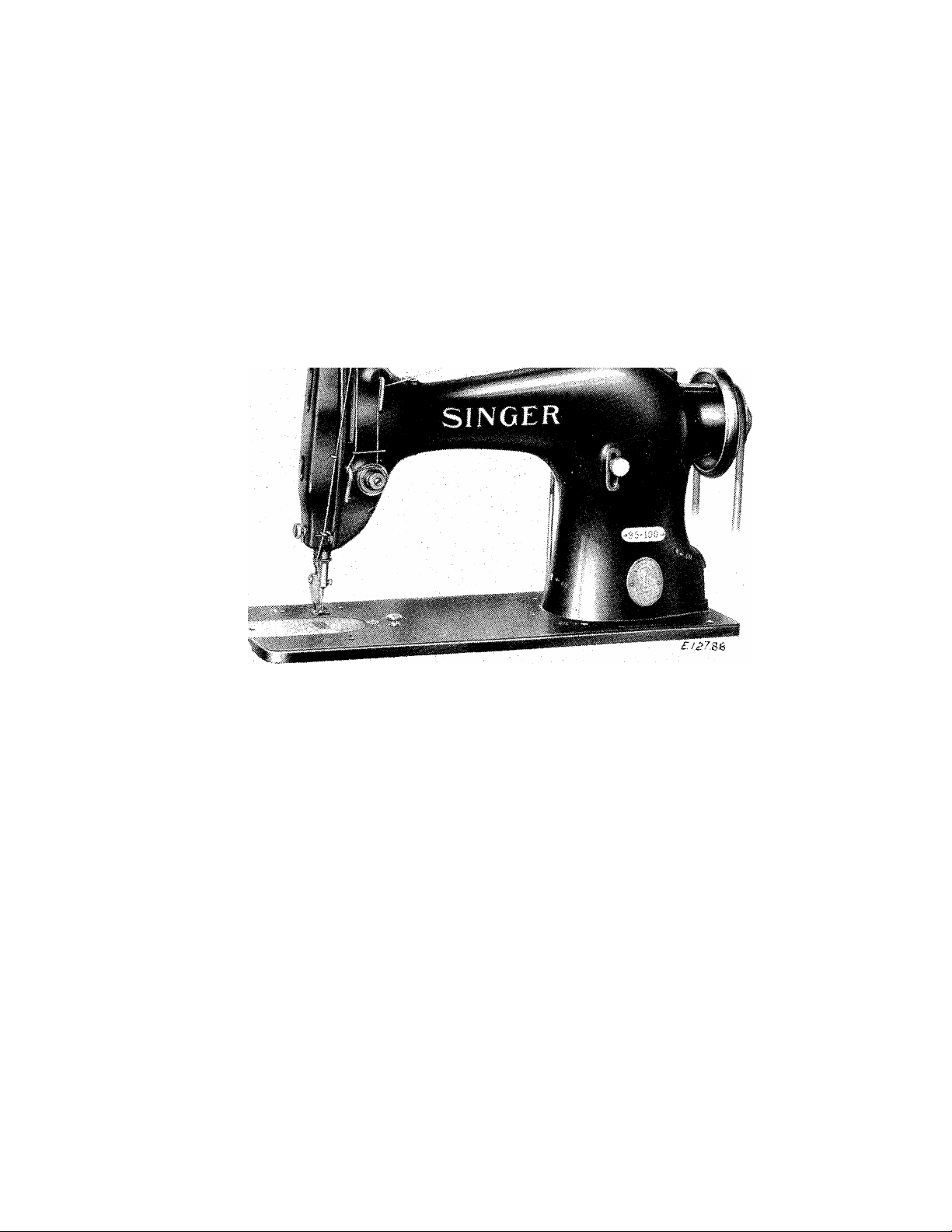
MACHINE: 95-30 makes the lock stitch and Is designed for sewing
light and medium weight fabrics. It has a gear-driven rotary hook.
The needle bar stroke Is 1-9/64 inches.
The machine is equipped with heavy gear shafts and three plain
bearings for the arm shaft.^^^^
MACHINE 95-100 is the same as Machine 95-80 except that it is
equipped with ball bearings at both ends of the arm shaft, the in
termediate bearing being a plain bearing.
MACHINES 95-80 and 95-100'should be run at- speeds not exceed
ing 3500 stitches per minute for the first two or three days, af
ter which they can be driven up to their maximum speed of 4200
stitches per minute, depending upon the nature of the work and the
ability of the operator.
Page 4
To Lubricate the Machine
USE "TYPE B" or "TYPE D" OIL, sold only by Singer Sewing
MacbIne company. For description of these oils, see Inside of
front cover.
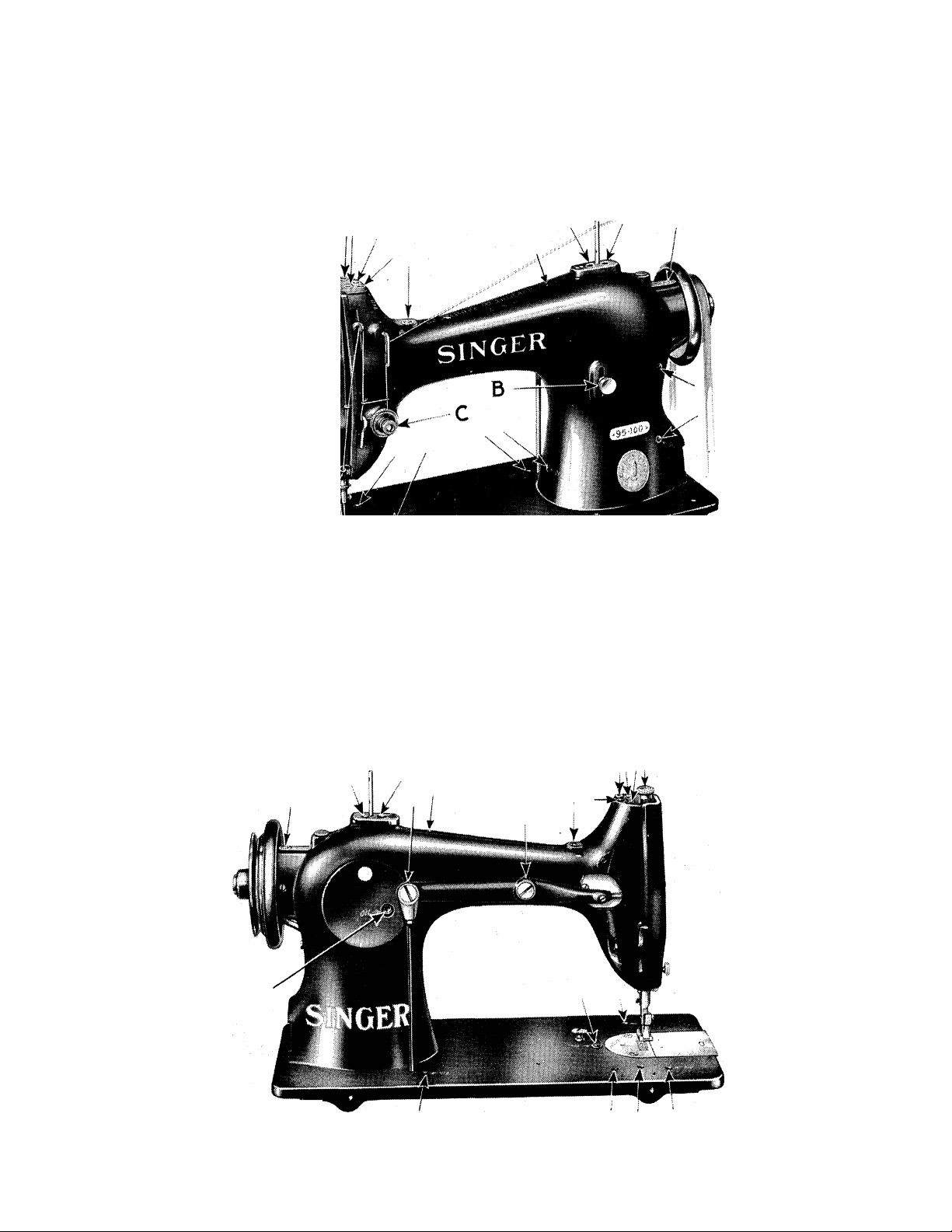
Fig.2. Oiling Points at Front of Machine
Oil should be applied as shown by arrows In Figs.2,3 and 6,
and, when used continuously, the iTEchlne should be oiled at least
four times each day. Keep all wicklng saturated with oil.
£/¿»543
Flg.3* Oiling Points at Back of №chlne
Page 5
use GEAR LUBRICANT in the gear cases of these machines.
When the machines leave the factory, the gear cases are packed
with sufficient GEAR LUBRICANT for approximately 160 hours of
of operatlcm.
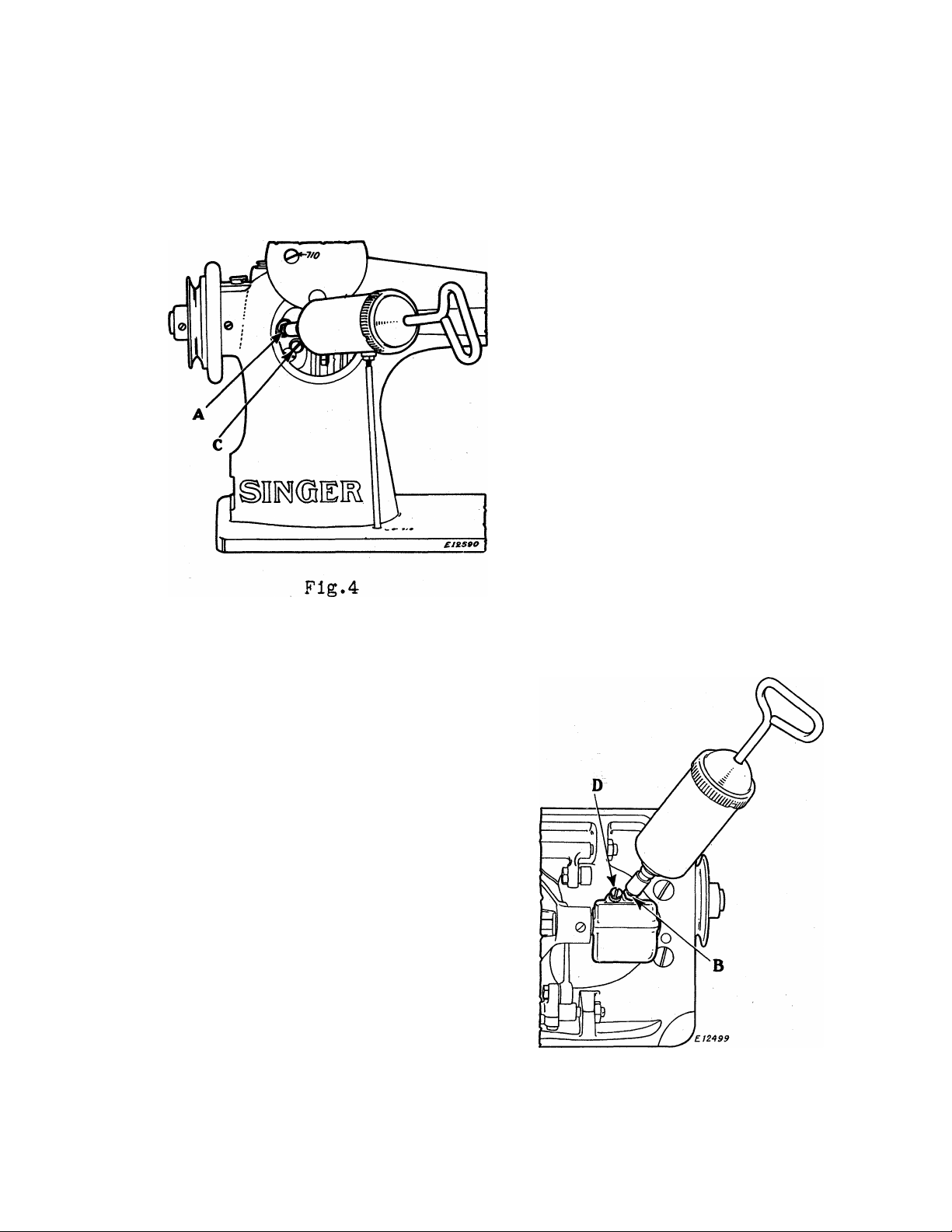
Replenish the gear cases
at (A) and (B), Figs. 4 and 5
with GEAR UJBRICANT every 160
hours of opérât im.
Alemlte Grease Guns,
SINGER NO. 121587 (3 oz. ca
pacity) or SINGER NO. 121588
(1/2 Ih. capacity) provide the
most ccxivenlent means of apply
ing GEAR LUBRICANT to the
gears.
To supply grease to the
upper gear case (Flg.4), have
the machine In its normal
working position, remove the
level hole screw (C,Fig.4) and force the lubricant into the Ale
mlte fitting (A,Fig.4) until
it emerges from the level hole
at (C), then replace the screw
(C).
To supply grease to the
lower gear case (Fig.5), lay
the machine back on the table,
remove the level hole screw
(D,Fig.5) and force the lubri
cant into the Alemlte fitting
(B,Fig.5) until it emerges
from the level hole at (D),
then replace the screw (D).
Flg.5.
CAUTION - To avoid overfilling of the gear cases, do. not turn
the balance vheel when grease is being applied through the Alemlte
fittings.
Page 6
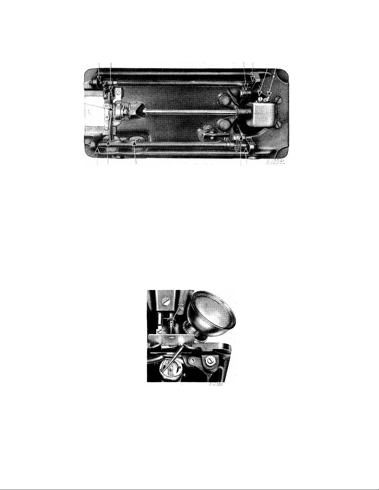
Fig.6. Oiling Points In Base of Machine
D iB
At least four times each day apply ONE DROP of oil to the
bobbin case holder bearing In the sewing hook race, as shown In
Fig.7.
Fig.7. Oiling Point In Hook xRace
CAUTION. NEVER OIL THE SEWING HOOK PJ^lCE THROUGH THE' NEEDLE
HOLE IN THE THROAT PLATE, NOR FLOOD THE HOOK WITH OIL.
Page 7
Needles
Needles for Machines 95-SO and 95-100 are of Class and Variety
S8 X 1, and are furnished In Sizes 9, 11, 13, 14, 16, 17, IS, 19
and 21.
The size of the needle to be used should be determined by the
size of the thread which must pass freely through the eye of the
needle. Rough or uneven thread, or thread which passes with dif
ficulty through the eye of the needle, will interfere with the
successful use of the machine.
Orders for needles must specify the QUANTITY required, the
SIZE NUMBER, also the CLASS and VARIETY NUMBERS separated by an x.
The following Is an example of an Intelligible order;
"100 No.16, 88 X 1 Needles"
The best stitching results will be obtained by using the
needles furnished by the Singer Sewing Machine Company.
Thread
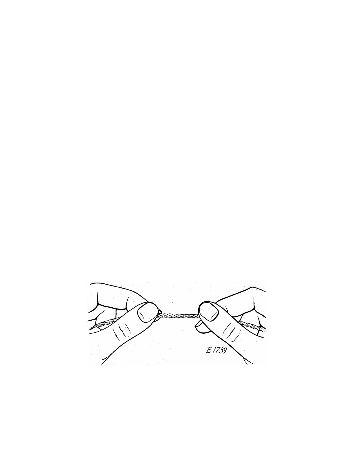
Left twist thread should be used in the needle,
Either right
or left twist thread can be used in the bobbin.
Fig.8. How to Determine the Twist
Hold the thread as shown above. Turn the thread over toward
you between the thumb and forefinger of the right hand; If left
twist, the strands will wind tighter; If right twist, the strands
will unwind.
Page 8

6
Relative Sizes of Needles and Thread
The following sizes of needles and thread are recommended ac
cording to the class of work:
Sizes
of
Needles
14
16
and
17
18
19
Classes of Work
Shirtings, Sheetings, Calicoes, Muslins,
Silks, Dress Goods and all classes of
general work.
All kinds of heavy Calicoes, light
Woolen Goods, heavy Silk, Seaming,
Stitching, etc.
Tickings, Upholstery, Woolen Goods,
Trousers, Boys^ Clothing, Cloaks, etc.
Heavy Woolens, Tickings, Bags, Heavy
Coats, Trousers, Heavy Clothing gener
ally.
Sizes of
Cotton, Linen
or Silk
60 to 80 Cotton
A and B Silk
40 to 60 Cotton
C Silk
30 to 40 Cotton
D Silk
24 to 30 Cotton
E Silk
60 to 80 Linen
21
Bags, Course Cloths and Heavy Goods.
16 to 20 Cotton
40 to 60 Linen
To Insure Perfect Action of the Machine
The balance wheel must always turn over toward the operator.
DoTiot run the machine with the presser foot resting on the
feedwithout cloth under the presser foot.
Do not run the mchlne when both bobbin case and needle are
threaded unless there Is material under the presser foot.
" Do not try to help the machine by pulling the fabric lest you
bend the needle. The machine feeds the work without assistance.
The slide over the bobbin case should be kept closed when the
machine Is In operation.
Page 9
7
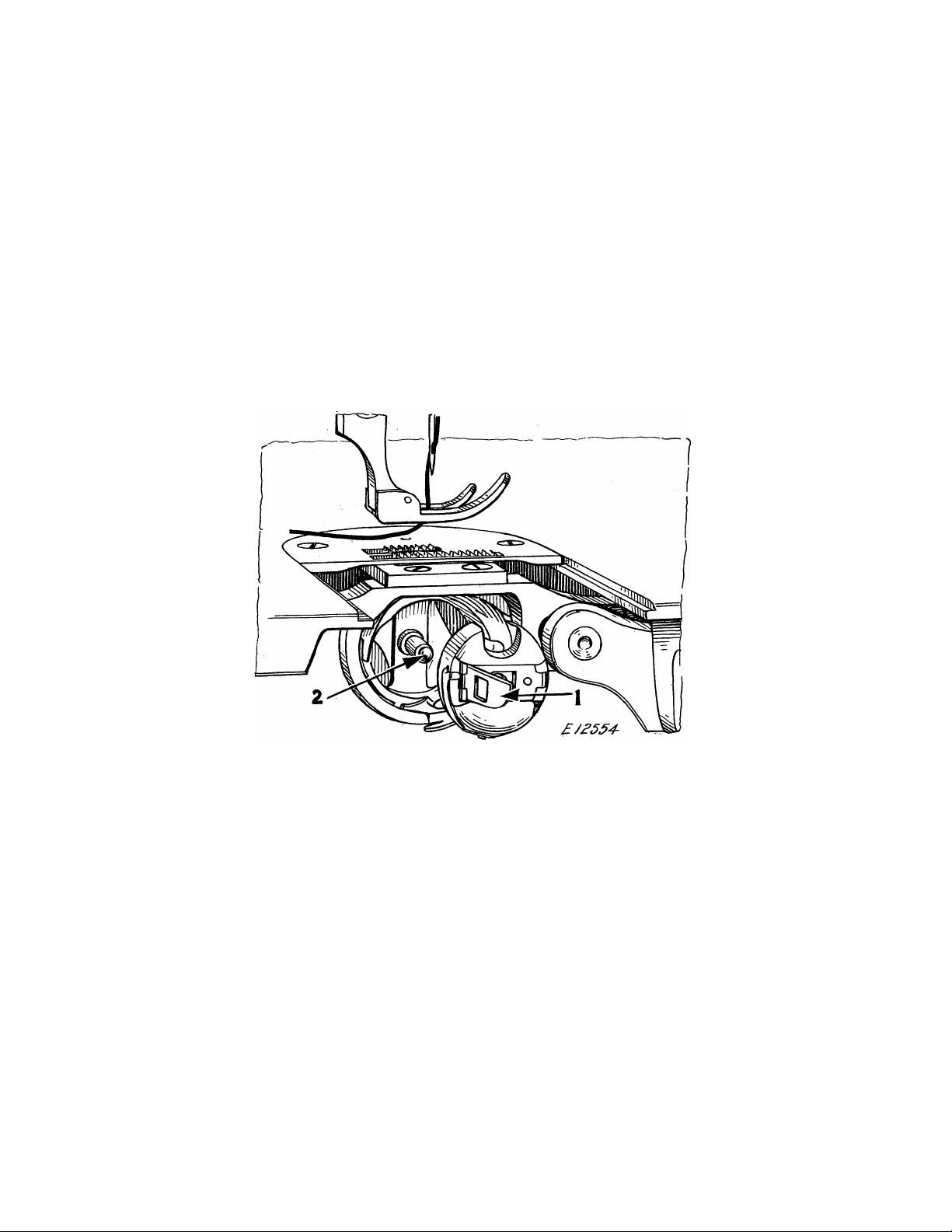
To Remove the Bobbin
Turn the balance, wheel over toward you until the needle moves
up to Its highest point. Draw out the slide In the bed of the ma-
Flg.9. Removing the Bobbin
chine. Open the bobbin case latch (l,Flg.9) and, by means of
this latch, remove the bobbin case from the sewing hook.
While the latch remains open, the bobbin will be retained In
the bobbin case. Release the latch, turn the open end of the bob
bin case downward and the bobbin will drop out.
Page 10

8
To Wind the Bobbin
(See Fig.10)
Fasten the bobbin winder to the table with Its driving pulley
In front of the machine belt, so that the pulley will drop away
from the belt when sufficient thread has been wound upon the bob
bin.
£/г557
Fig.10. Winding the Bobbin
Place the bobbin on the-bobbin winder spindle and push It on
as far as It will go.
Pass the thread down through the thread guide (1) in the ten
sion bracket, around the back of, and between,the tension discs
(2). Then wind the end of the thread around the bobbin a few
times, push the bobbin winder pulley over against the machine
belt and start the machine.
When sufficient thread has been wound upon the bobbin, the
bobbin winder will stop automatically.
If the thread does not wind evenly on the bobbin, loosen the
screw (A) In the tension bracket and move the bracket to the
right or left as may be required, then tighten the screw.
The amount of thread wound on the bobbin Is regulated by the
screw (B). To wind more thread on the bobbin, turn the screw (B)
Inwardly. To wind less thread on the bobbin, turn this screw
outwardly.
Bobbins can be wound while the machine Is stitching.
Page 11

^ :0'
To Thread the Bobbin Case
Hold the bobbin between
the thumb and forefinger of
the right hand, as shown In
Fig.11, the thread drawing on
the bottom from the left to
ward the right.
C/P5
Fig.11
with the left hand hold the bob
bin case as shown in Fig.11, the
slot In the edge being near the top,
and place the bobbin Into It.
Then pull the thread Into the slot
In the edge of the bobbin case as
shown in Fig. 12; draw the thread under
the tension spring and Into the deliv
¿■72560
ery eye at the end of the tension
spring (see Fig.13).
Fig. 12
Fig.13
Page 12

10
To Replace the Bobbin Case
After threading, take the bobbin case by the latch and place
the bobbin case on the center stud (2,Fig.9) of the bobbin case
Fig.14. Bobbin Case Threaded and Replaced
holder; release the latch and press the bobbin case back until
the latch catches the groove near the end of the stud (See Fig.9).
Allow about two Inches of thread to hang free, ind replace the
slide In the bed of the machine.
To Set the Needle
Turn the balance wheel over toward you until the needle bar
moves up to Its highest point; loosen the screw In the lower end
of the needle bar and put the needle up Into the bar as far as It
will go, with the long groove of the needle toward the left and
the eye of the needle directly In line with the arm of the ma
chine, then tighten the screw.
Page 13

11
upper Threading
Pass the thread from the unwinder, or from the spool on the
spool pin on the top of the machine, from right to left through
£/2639
Fig.15. Upper Threading
the top hole (1) in the thread retainer, from left to right
through the center hole (2) in the thread retainer, and from
right to left through the bottom hole (3) in the thread retainer,
down under and from right to left between the tension discs (4),
into the thread take-up spring (5), under the slack thread regu
lator (6), up and back of the wire thread guide (7), up and from
right to left through the hole in the end of the thread take-up
''lever (8), down through the thread guide (9), down through the
thread eyelet (10), Into the thread guide (ll), and from left to
right through the eye of the needle (12). Draw about two Inches
of thread through the eye of the needle with which to commence
sewlno:.
Page 14

12
To Prepare for Sewing
Vlth the left hand hold the end of the needle thread, leaving
It: slack: fГОШ the hand to the needle^ turn the balance wheel over
Fig.16. Drawing Up the Bobbin Thread
toward you until the needle moves down and up again to its highest
point, thus catching the bobbin thread; draw up the needle thread
and the bobbin thread will come up with it through the hole in the
throat plate (see Fig.16). Lay both threads back under the presser foot.
To Commence Sewing
Place the material beneath the presser foot, lower the presser
foot and commence to sew, turning the balance wheel over toward
you. ■ .
To Remove the Work
Let the thread take-up lever rest at its highest point, raise
the presser foot, draw the work back and cut the threads close to
the goods.
Page 15

13
Tensions
For ordinary stitching, the needle and bobbin threads should
be locked in the center of the thickness of the material, thus:
Fig.17. Perfect Stitch
If the tension on the needle thread Is too tight, or If that
on the bobbin thread Is too loose, the needle thread will lie
straight along the upper surface of the mterlal, thus:
Fig.18. Tight Needle Thread Tension
If the tension on the bobbin thread is too tight, or If that
on the needle thread Is too loose, the bobbin thread will lie
straight along the under side of the material, thus:
Fig.19. Loose Needle Thread Tension
To Regulate the Tensions
THE TENSION ON THE NEEDLE THREAD SHOULD BE REGULATED ONLY
WHEN THE PRESSER FOOT IS DOWN. Having lowered the presser foot,
turn the small thumb nut (C,Flg.2), at the front of the tension
discs, over to the right to Increase the tension. To decrease
the tension, turn this thumb nut over to the left.
The tension on the bobbin thread Is regulated by the large
screw (FF,Fig.ll) In the tension spring on the outside of the
bobbin case. To increase the tension, turn this screw over to
the right. To decrease the tension, turn this screw over to the
left.
When the tension on the bobbin thread has been once properly
adjusted. It Is seldom necessary to change It, as a correct stitch
can usually be obtained by varying the tension on the needle
thread.
Page 16

14
To Regulate the Length of Stitch
The -length of stitch is regulated by the thumb screw (B,Flg.
2) in the slot on the front of the upright part of the arm. To
lengthen the stitch, loosen this thumb screw and move it down
ward. To shorten the stitch, loosen this thumb screw and move
It upward. When the desired length of stitch has been obtained,
tighten the thumb screw (B).
To Regulate the Pressure bn the Material
The pressure on the material Is regulated by the thumb screw
(D,Flg.2) . To Increase the pressure, turn this thumb screw over
to the right. To decrease the pressure, turn this thumb screw
over to the left.
SINGER Needles should be used
in SINGER Machines.
These Needles and their Containers
are marked with the
Company’s Trade-Mark “SIMANCO.*” 1
Needles in Containers marked
“FOR SINGER MACHINES”
are NOT SINGER made needles. 2
Page 17

INSTRUCTIONS
FOR
ADJUSTERS AND A\ACHINISTS
Page 18

16
To Set the Needle Bar at the Correct Height
See that the needle Is pushed up into the needle bar as far
as It will go, then remove the face plate.
The needle bar,
which is in the machine
when shipped from the
factory, has two timing
marks near its upper
end. Rotate the bal
ance whee1 unt i1 the
needle bar moves down
to its lowest position.
The UPPER TIMING MARK
on the needle bar
should then be centered
with the lower end of
the needle bar bushing,
as shown at (D) in Fig.
20. In case the needle
bar is not set at the
correct height, loosen
screw (E,Flg.20) and
move the needle bar up
or down until the UPPER
TIMING MARK is centered
with the lower end of
the needle bar bushing,
as shown at (D,Fig.20),
then securely tighten
screw (E).
Fig.20
Needle Bar Set at Correct Height
In the event that
the setting of the
needle bar bushing has
been disturbed, thus making it impossible to set the needle bar
for correct height by centering the upper timing mark with the
lower end of the needle bar bushing, turn the balance wheel to
bring the hook point to the center of the needle, loosen screw
(E) and move the needle bar up or down to bring the top of the
needle eye 1/32 inch below the point of the hook, then securely
tighten screw (E). Loosen the needle bar bushing set screw at
the top of the machine arm and, while the hook point is at the
center of the needle and 1/32 inch above the top of the needle
eye, move the needle bar bushing up or down to bring its lower
end exactly even with the LOVER TIMING MARK on the needle bar,
then securely tighten the needle bar, bushing set screw.
Page 19

17
To Time the Sewing Hook
Remove presser foot, slide plate, throat plate and bobbin
case. Take out the two screws (E2,Flg.20) and remove feed dog.
Fig.21. Needle and Sewing Hook Correctly Timed
To determine that the hook Is correctly timed, place a new
needle In the machine, then turn the balance v^eel over toward
you until the LOWER TIMING MA.RK on the needle bar Is centered
with the lower end of the needle bar bushing as shown at (Q,Flg.
21)vWhen the needle bar Is on Its upward stroke. With the
needle bar In this position, the point of the hook should be at
the center of the needle as shown at (R,Flg.21). The Inset In
circle at the left of Fig.21 plainly shows this position of the
hook point relative to the needle.
Page 20

18
In case the hook is not correctly timed, loosen the three
screws (L,Flg.22) In the hub of the hook. These three screws
can be reached from the top of the machine bed through the open-
Flg.22. View of Underside of Machine
Showing Bobbin Case Holder Position Bracket (H)
and Adjustments on Pfeichlne
Ing left by the removal of the throat plate, although, for pur
poses of Illustration, the screws are shown only In the view of
the underside of the machine In Fig.22. Rotating the balance
wheel of the machine will bring these screws, one at a time,
directly under the throat plate opening where they can be easily
reached with a screwdriver from the top of the machine bed.
After loosening the three screws (L,Flg.22) turn the hook on
Its shaft to bring the point of the hook at the center of the
needle as shown at (R,Fig.21), then tighten the three screws (L,
Fig.22).
The hook should be set as close as possible to the needle
without touching. If the hook Is too close to the needle or too
far away from It, loosen the three screws (L,Fig.22) and the bush
ing screw (J,Fig.22) and drive the bushing (K,Fig.22) In or out,
as may be required, until the hook Just clears the needle, being
very careful not to damage the bushing, then securely tighten the
bushing screw (J) and the three screws (L).
Page 21

19
To Remove and Replace the Sewing Hook
Remove the needle, slide plate and bobbin case. Take out the
screw (G,Fig.22) and remove the bobbin case holder position
Fig.23. Showing Correct Position of Thread Guard (U) and
Bobbin Case Holder (P) for Removal of Sewing Hook
bracket (H,Fig.22). Loosen the three set screws (L,Fig.22) in
the hub of the hook, then turn the balance vdieel over toward you
until the feed bar (S,Fig. 23) is raised to its highest point.
Turn the sewing hook until the thread guard (U,Fig.23) is at the
bottom, as shown in Fig.23, and turn the bobbin case holder (P,
Fig.23) until it is in the position shown in Fig.23. The sewing
hook can then be removed from the hook shaft.
When placing a new sewing hook on the shaft, have the thread
guard (U) of the hook at the bottom and the bobbin case holder
(P) turned to the position shown in Fig.23, so that the hook will
clear the feed bar (S).
When the hook is in position on the shaft, turn the bobbin
case holder (P,Fig.23) until the notch (T,Fig.23) is at the top,
then replace the bobbin case holder position bracket (H,Fig.22)
being careful to see that the position stud (M,Fig.22) enters the
notch at the top of the bobbin case holder, as shown in Fig.22,
Page 22

20
then securely fasten the position bracket by means of the screw
(G,Fig.22). Replace the needle and time the sewing hook as In
structed on pages 17 and 18. When tightening the three screws
(L,Fig.22) In the hub of the hook, draw the hook shaft toward the
needle bar end of the mchlne and press the hook toward the bal
ance wheel to take up the end play In the shaft. Then replace
the bobbin case and slide plate.
To Remove and Replace the
Sewing Hook Shaft
Remove the sewing
hook as Instructed on
page 19. Take out
the screw (V,Flg.24)
and remove both sec
tions of the gear
case (V,Fig.24), then
wipe the grease away
from the gears.
Before removing
the hook shaft (X,Flg.
25) from the machine,
the gears (Y and Z,
Fig.25) should be
marked with chalk or
red pencil on one of
the teeth of the gear
(Y) and the space of
the gear (Z) In which
the marked tooth
meshes. This Is Im
portant, as the gears
may become dislodged
when removing the
hook shaft, and the
marks will enable you
to retain the origin
al relative positions
Fig.24. Vlev^k of Underside of №chlne of the gears.
Showing Gear Case
To remove the hook shaft, loosen the two set screws in the
gear (Y,Fig.25), then insert the new hook shaft Into the gear
Page 23

SI ■
(y), from the right hand end, pushing thp old shaft out of the
gear toward the needle bar by means of the new shaft, as shown
Fig.85. Removing and Replacing Sewing Hook Shaft
In Fig.25. By removing the old shaft In this manner, the rela
tive positions of the gears (Y and Z) will not be disturbed.
When placing the new shaft In position In the machine, see that
the flat portion near one end of the shaft Is at the right so
that one of the set screws In the gear (Y,Flg.25) will bear
against It when the gear Is fastened In position on the shaft.
The shaft should be set so that Its left end Is flush with the
front (left hand) side of the body of the sewing hook.
When the shaft Is correctly positioned, securely tighten the
two set screws In the gear (Y), making sure that one of these two
screws bears against the flat portion of the shaft.
Time the sewing hook as Instructed on pages 17 and 18.
Replace the gear case and securely fasten It In position by
means of the screw (V,Flg.24).
Page 24

22
To Adjust the Thread Take-up Spring
The thread take-up spring (Ci2,Flg.26) should be set so that
when the eye of the needle reaches the goods on the downward
Fig.26. Adjustment of Thread Take-up Spring
stroke of the needle bar, the spring will be through acting and
will rest against the stop on-the thread take-up spring regulator.
If the thread take-up spring Is not correctly set, as Instructed
above, loosen the set screw (R2,Flg.26) In the arm of the machine,
and turn the tension stud (S2,Flg.26) to the right for more move
ment of the spring or to the left for less movement. When the
spring Is-correctly set, securely tighten the set screw (R2).
The tension on the thread take-up spring (Q2) Is regulated
by turning the tension stud (S2) to the right to Increase the
tension, or to the left to decrease the tension. The tension on
the thread take-up spring should be just sufficient to take up
the Slack of^the needle thread until the eye of the needle
reaches the goods In Its descent.
Timing of the Feeding Mechanism
When the machine leaves the factory, the feed eccentric Is
correctly set by having the timing screw In the eccentric enter
the groove In the arm shaft. If, for any reason. It may be nec
essary to alter the timing of the feed eccentric, loosen the
timing screw and the set screw, turn the eccentric as required
tighten the set screw only.
Page 25

THE IMPORTANCE OF
USING SINGER* PARTS AND NEEDLES
IN SINGER MACHINES
The successful operation of SINGER machines can only be assured
if SINGER parts and needles are used. Supplies are available at all
SINGER Shops for the Manufacturing Trade, and mail orders will receive
prompt attention.
Page 26

Page 27

SINGER Needles should be used
In SINGER Machines.
These Needles and fheir Confolrsers
are marked with the
Gomparsy*$ Trode«Mark“SiMANCO.^
Needles In Containers marked
"FOR SINGER MACHINES**
are NOT SINGER made needles»
Page 28

 Loading...