

Singer 831U, 832U User Manual
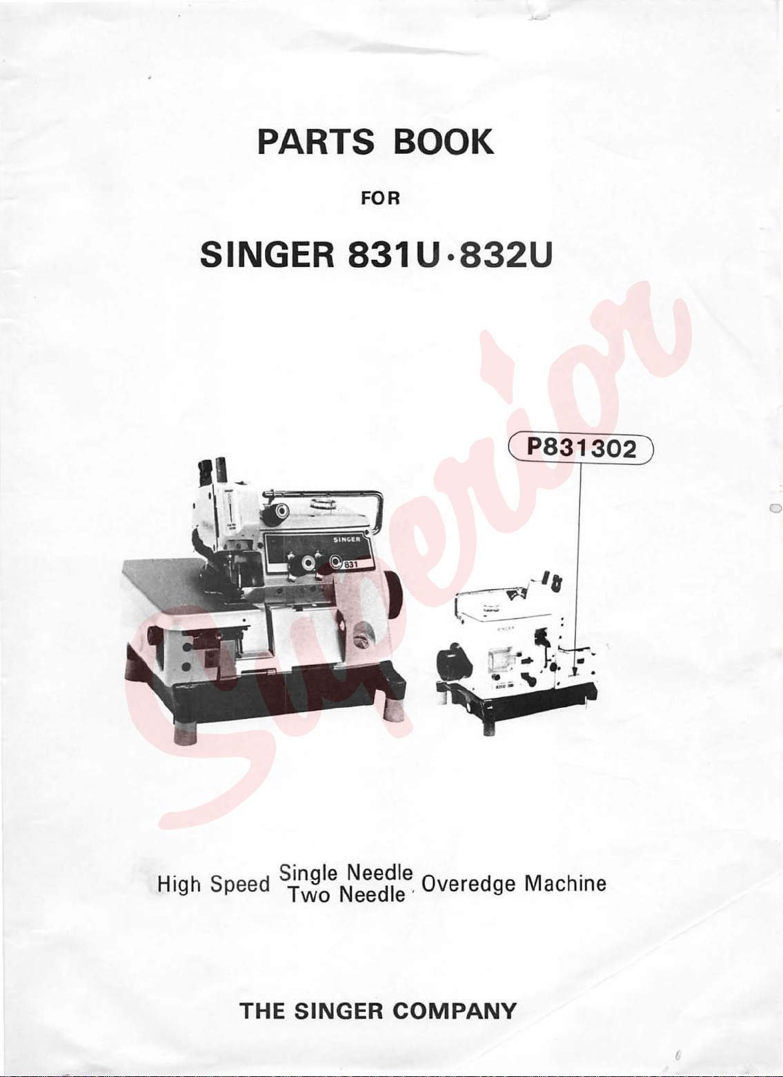
PARTS BOOK
FOR
SINGER
831U·832U
P831302
0
High Speed Sin_gle Needle Overedge
Two
THE SINGER
Needle ·
COMPANY
Machine
1.
2.
This
parts
number
These
is
same
pages
book
from
can
as
How
be
shown
A-H,
to
used
for
on
the
Z, Y on
use
ordering
upper
this
001-().
3.
When
I 000000-0-00 I
4.
When
But
by
sembled
5.
The
to
6.
After
when
the
parts
be
the
the
parts
parts.
which
fitted.
page
column
please
column
the
parts
assembly
number
Therefore,
9,
please
for
the
refer
for
the
assembly
number
please
refer
parts
to
the
parts
is
marked
to
different
number
number
so
order
the
different
number
that
with * is
CONTENTS
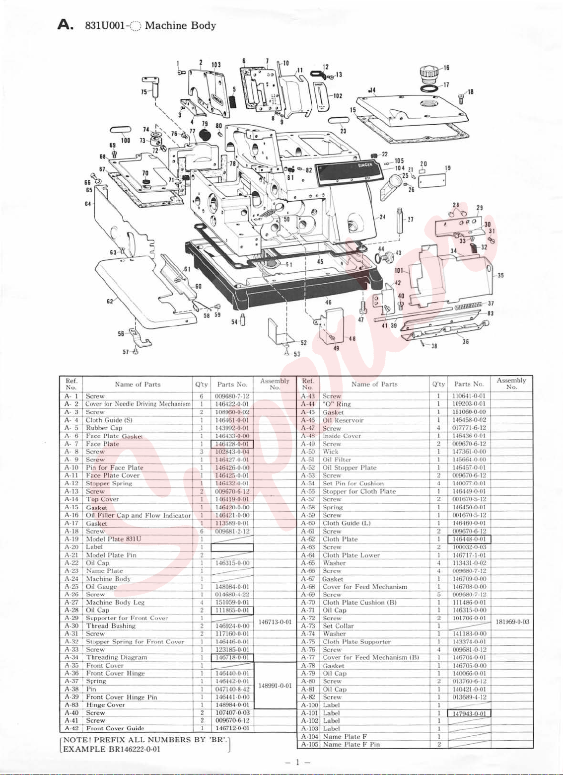
A.
831U001-() Machine Body
831
U001-()
B .
C.
831U001-() Looper Mechanism
D .
831
U001-() Feed Mechanism. . . . . . . . . . . . . . . . . . 4
E .
831
U001-:::::::
831
U001-:::)
F .
G .
831
U001-:::::>
H.
831
U001-() Needle Cooler . . . . . . . . . . . . . . . . . . . . 8
831U002-() (Bulky Knit Work).
I .
J .
831
U003-() (Blind Stitch Hemming) . . . . . . . . . . . 9
831
U004-() (Blind Stitch Hemming)
I' .
1'.
831U006-:::::::
M.
831
U005-:::) (Serging)
M:
831
UOIO-:::::::
K.
831
U008-:::::>
L.
831U009-:::::;
N.
831
UOll-:::::::
N'.
S31U012-:::::>
K'.
831U007-:::::>
P . Cord Guide
Q . Ruffler Interlocking
Y . Accessories
Z.
Machine
a . Common
832U021-:::::::
b
· (Light Work) · ·
832U022-:::::::
c · (Light and Medium Work)· · · · · · · · ·
832U023-:::::::
d
· (Light and Medium
Crank
Shaft
Knives
and
Threading.
Lubrication. . . . . . . . . . . . . . . . . . . . . . . 7
(Serging)
(Taping on Light, Medium Work)
(Ruffling)
(Ruffling (W/Piping) )
(Taping on Bulky Knit Work)
(Chain-back)
(Tum-down Hemming)
..................................
..................................
Base
Plate
and
Parts
for All 832U Varieties
Needle Gauge
Needle Gauge
Needle Gauge
....................
and
Needle
Bar
Mechanism.
................
Presser
Foot
Mechanism.
. . . . . . . . . . . . . . . . . . . . . . . 6
...............
...........
.........................
.........................
.........................
..............
......................
............
Parts
Thread
Assembly
Unwinder 3 THF
1.8
2.2
2.2
...........
........
.........
mm
.. · .. · ....
mm
mm 2
Work)'········
. . . 2
. . . . . . 5
...
......
the
parts
of
cover
parts
or
parts
is
I~
is
shown
the
parts
not
the
parts
parts
,
1
3
9
10
10
11
11
12
13
14
15
15
16
17
18
19
20
20
·
21
832U024-() Needle Gauge 3 mm
b
· (Light and Medium
, 832U025-() Needle Gauge 3 mm
c · (Light and Medium Work)· · · · · · · · ·
,
832U026-:::) Needle Gauge
d
· (Bulky Knit Work) · · · ·
832U027-()
e · (Bulky Knit Work) · · · · · · · · · · · · ·
, 832U028-() Needle Gauge
e · (Bulky Knit Work)
f
· (Extra Heavy
,
f
· (Extra Heavy Work) · · · · · · · · · · · · · ·
g · (Ruffling) · · ·
,
g · (Ruffling) · · · ·
h ·
,
h
· (Ruffling (W /Piping)) ·
. 832U041-() Needle Gauge
l · (Taping on Light, Medium
k 832U045-() Needle Gauge
· (Taping on Bulky Knit Work)· · · · · ·
m.
n · (Piping)
z .
DIFFERENT PARTS LIST
INDEX
1
book
the
parts
of
the
catalogue
parts
assembly
list
on
in
the
can
lapped
together
list
on
832U031-() Needle Gauge 3 mm
832U032-() Needle Gauge 3 inm
832U033-:::::>
832U034-:::::::
832U037-C·::
832U038-() Needle Gauge
832U049-c·::
832U050-()
Thread
..........................................
of
the
machine
book
(or
correction
show
the
I,
column,
be
together
with
the
Needl~
Needle Gauge
Needle Gauge
Needle Gauge
···
(Ruffling
Needle Gauge
···
(Chain-back) · · · · ·
Needle Gauge
Unwinder 4
all
the
number
page
37.
the
parts
please
arranged_in
with
the
fitting
page
37.
Gauge
Work)··············
(W
/Piping)) · · · · · · ·
THF
.....................
......................
is
cannot
1.8
mm
2.2
mm
2.2
mm
2.2
mm
2.2
mm
2.2
mm
2.2
mm 3
2.2
mm
2.2
mm
2.2
mm
2.2
mm .
sheet).
parts
I
order
the
except
parts
Work)··
which
be
form
........ · ....
.. · ..
.. · ..
plate
for
831U-
supplied.
the
parts
of
the
parts
as
a unit.
· · · · · · ·
..
· · · · · · ·
..
· · · ·
....
......
.. · ..
· · · ·
Work)'··
.. · ....
· · · ·
..
· · ·
..
as-
22
22
23
24
25
26
27
28
29
30
·
·
32
34
·
· · v
I,
33
3
36
37
45
1
~
A.
831
65
64
UOOl-()
Machine
Body
35
62
I
5~
~
57
~
Ref.
Ko
.
I
A·
A- 2 Cover for l'\ccdlc Drivmg Mechanism
A- 3
A· 4
A- 5
A- 6
A- 7
8 Screw
A·
A· 9
A-10
A-l l Face Pla
A-
12
A-
13
A-14
A-
15
A-
16
;mGas
A-18
~
A-20 L
A-21 I :'-lode!
A-22
A-23
A-
24
A-25 Oi l
A-26
A-27
A-28 I O
A -29
A ·30 I
A-3 1 Scre w
A-32
A-33 Screw
A-34
A-35
A-36
A-37 Spnng
A-38
A-39
A-
83 Hinge
~
A-41 Screw
A-42 ;
NOTE!
EXAMP
Name
of Part
Screw
Screw
Cloth
Guid
ce
Plate Ga
Plat
for Face
pper Spr
Cover
t
iller Cap
ke
t
abe
l
1l
Cap
arne
Plat
Gauge
rew
il Cap
rter
ead
Cover II
Cover llinRe
Cover
nt
Cover G,Jdc
PREF
e (5)
sket
e
Plate
te Co
ver
ing
and l
Plate 831 U
Pla
te
Pin
e
Bo
dy
e B
ody
Leg
---
for Front C
B
u s
hm~
Sprmg
D1agram
ingc
--
IX
ALL
--
for Front Cover
Rubber Cap
Fa
Face
Sere\\'
Pin
Sto
Screw
T op
Gaske
Oil F
Screw
~lode!
0
:"
~lachine
Sc
:\lachin
Suppo
Thr
Stopper
Threading
From Co'"cr
Front
Ptn
Front
Screw
Fro
LE BRI46222-0-0 I
s
~
'low Indicator
-
over
Pin
NUMBE
ff_J
A
Q"ty
Pans i'\o.
6
009680
22:0:01
I
1464
2
I 08960·0-02
I
146461-0-01
I
14
3992·
146433-0-00
I
146-128-0-
I
I
1028-l3-0·0.1
3
I
1464
27-0-0~-
14
6426-0·00 A-52
I
I
146-125·
146-13
I
2
I
I
I
I
6
I
I
2
I
I
}-'~
I
I 148084
I 01461!0-4-22
4
2 111865-0-
I
2
2 117160·0·01
I
I 123185-0
I 146718·0-01 A-77
I
I
I
I 1464-10·0-0l
I 146442-0-01 A-80
I 0.17140·8··12
I 14644 1·0·00 A-82
I
2 107407-02
I 146712-0-
RS
BY
2·0·01
009670-6-12 A-56
146419-0-01
146,120-0-00 A-58
146421·0·
)
13
589·0-01 A·
009681
::::::=:----
--
--
151059-0-0l
146924:0:00
--
14
64-16-o:ol
-
14
8984-0-
009670
'BR'.
sse
-7-
12
0·0
1
01
----
--
f--
0·0
I
00
t-
-2-
12
-0-
01 A-
01
146713·0-
--
-01
14
8991·0·01
01
03
·6· 1
~
01
I
I
52
~
mbly Ref.
No
. No.
A-43
A-
A-45
A-
A-47
A-48
A-49
A-50
A-5
A-53
A-54
A
A-59
A-61
A-62
A
A-64
A-65
A -66
A
AA-70
A-71
A-72
01
A-73
A-74
A-75
A-76
A-78
A-79
A-8 1
A-100
A-1
A-102
A-103
A·I04
A-105
-I
r\'amc
of
Part
---
Sere\
\'
44
"
Gasket
46
Oil l<escrvoir
Scr
lnsi
Screw
W
1
Oil
Oil
Screw
Set Pin for Cus
St
-57
Sc
Spring
Screw
Cl
60
Scr
Clo
-&1
Scre
Cloth Plate Lo w
\\'asher
Scr
-67
Gasket
68
Co
69
ScrC\\'
Clo
O
Sere
Se
W
Cloth
Scr
Cover
Gasket
Oil
Screw
Oil
Screw I
Lab
~~
~
Lab
Label I
Name Plat
Nam
---
0"
!linK
__
ew
deC~
--
ick
F1
ltcr
St<>pper Pla
OPI>Cr
for C loth
rew 2
---
oth
Guide (L) I
ew
th !'late
w 2
--
ew
---
ver
for
Feed Mechanism I
th !'late
il Cap I
ashe
Cush1on
'"
t C
olla
r
r
Plate Supporter
ew
fur Fe
('<!
Cap
Cap
el I
·
el
e F I
e Plate F Pin 2
s
te
hTon
Plat
e
er
----·-'---:j
(B) I 111486-0·
~lcchanism
-
·-
(Fl)
Q
'ty
Parts t"o.
I 110641-0-01
I
09203·0·0 I
I
I !
51
060-0-00
I 146-1
4 01777 1-6-12
I 146-1
2 009670-6-12
I 147361-0-00
I
14566-1-0-00
I
I
16457 -0·0 I
I
009670-6-12
2
4
I 10077 ·0·0 I
I 16-149-
I
00
1670
--
6-
,,1
I
I 0016
146-160·0·0 I
-----
2 009670-6-12
I
1464
I 00032-0-03
I 1·16717-1-01
113431-0-02
009680-7--,2
~
I 146709-0-00
'1
46708·0·00
009680-7-12
~
1463
2
10~
I
I 141183-0-00
I 1•13374-0-01
~
009681-0-12
r-r--
14670.1·0·0 I
I 146705·0-00
I 140066·0·0 1
2 013760-6·12
I 1·10.121·0·01
0 13689
I
''17943-0-01
I
--
-
----
--
58-0-02
36·0·01
0-0 I
-5-
--
150-0-
70-5- 12
48·0·0 I
!5-0-00
-'
1-12
-
12
-
01
01
Assemb
ly
Ko.
181969·0·03
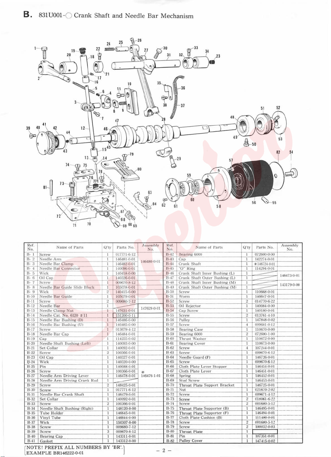
B. 831U001
-() Cra
nk
Shaft
and
Need
le Bar M e
chani
sm
71
70
nc
r.
No
.
R-
1
2
R-
B·
3
B· ·I
5
B·
B· 6
7 Scr
B·
8 Need le
B·
ll- 9 Wi
B-10
13
-11
B-12
"ir.i3 Needle Clamp l'\ut I 147631-0-01
11
·14
B-15
B-16
B-17
B-18
B-19
B-20
B-21 Set
B-22
B-23 Oil C
6·
24
B-25 Pin I 140088-0-01
B-26 Screw
B-
27
B-28
B-29
IB
-30
B-31
B-32
B-33 Scr
B-
34
B-
35 Tube
B-36
B-
37
B
-38
B-39 Scre w
13-
40 Bearing
B-4 1
NOTE
[
EX
AMPLE
Name
of
Part
s
Screw
Needle
Arm
Needle
Bar
Needle
\\'
ick
Oil Cap
Need
Screw
Needle
Need
Needle
Needle Bar Bus
Screw
l'\ecdle Bar
Ca p
Need
Scre
Wick
Needle
Needle
Screw
Screw
Needle
Set Colla
Ne
Vin
Wic k I
Screw
Gasket
! P REFIX A
Clamp
Bar
Connector
ew
Bar
Guide Slide Bl
ck
le
Bar
Guide
Bar
le
Cat. No.
6120
;:
Bar Bush
Cap
le Shaft Bushing
Collar
w 2 100366-0-01
ap
Ar m Driving
Ar m D
rivi
Ba r
Cra
r I 140092-0-01
ew
ed le
Shaft Bu
Holder
yl
T u
be
Cap
II
ing
(0)
hing
(U) I 146485-0-
(Left)
Lever
ng
Crank Rod
nk Sha
ft
sh ing
(Right)
LL
NUMBERS BY 'BR'.l
BRI46222·0·01
ock
Q't
y
Parts No.
I 017771-6-12
I 14648 1-0-01
I 146482-0-01
I 140096-0-0 I
I 140418-0-
I 140326-0-01
I 009670-8-12
I 105078-0·01
2 140415-0-
I 105079-0-01
2 009680·
I
-
I
151200-0-11
I 146486-0-00
I 013679-4-12
I 14&184-0-01
I
11
4255-0-02
I 140093-0-00
I 140092-0-01
I 140327-0-01
I 140320-0-
I
100366-0-01
I 146478-0-01
I
148425-0-01
2
--
I
017n l -6-12
146479-0-
I
100366-0-
2
I 148120-0I 146645
I 146644-0-
150307-0-
I 009680-7-12
009670-8-12
3
I 143311-0I 143312-0-
7.
-0-01
00
00
00
00
01
01
00
12
00
00
01
00
A
ssembly
No
.
14&180
-0-01
147629-0-
ll'
146476-1-01
-
R
ef.
No.
B-42
Rearing
13-43
Ca
B-44
Cra
B-45
"
0" Ring
B-46 C
rank Shaft
13-47 C
rank
Crank Sh
B-48
B-49
Cra
B-50
Sc
B-51
\Vo
R-
52
Screw
B-53 Oil Rejec
01
R-54 Ca p
B-55 Screw
B-56
Pulley
B-57
Screw
B-
58
Bearing
B-
59 Bearing
B-
60
Thrust Washer
B-61 Bearing Cover
B-
62
Sc
B-
63
Sc
B-64
Needle Guard
B-65
Scr
66
B-
C
loth Plat
B-
67
Cloth
B-
68
Spring
B-
69
St
B-70
Throa
B-
71
Nut
B-72 Screw
B-
73
Screw
B-74
Screw
B-
75
T hroat Plate Su
B-76
Throat
B-77
Clo
B-78 Screw
13
-79 Screw
B-
80
T hr oa t P late
B-
81
Pin
Pull
B-82
2-
p
nk Shaft
Sh a
nk Sh
rew
rm
Screw
rew
rew
e w
Plate L
ud Scr
t P la te
th P l
ey
Cover
Name
of
Part
6000
Inn
er Bus
ft Outer Rus
aft Inn
er Bus
aft Outer Bushi
tor
Case
6000
(F )
e L
ever Stoppe
ever
ew
Support
pporter
P la
te
Suppor
ate
Cushion (
s
hing
hing
hing
Bracket
te r
Bl
(B)
tFl
ng
A
sse
mbl
Q'ty
Parts No.
I
072600-0-00 I
I 142274-0 01
I
..
1~672~
0-0
I
(L)
(L)
(M)
(1\ll
r
114294-0-01
I
I
I
--
I
I 110668-0-01
I 1·16647-0-01
2 014770-6-22
I 140084-0-
I 140180-0-01
2 013761 -4-10
I
14
4 009681-0-1
11
I
2 O
I 110672-0-00
I 110673-0-00
4 I 07244 -0·0 I
I 009670-6-1
146726-0-01
I
I 009670-6·12
I 146454-0-01
I 1
14645~-0-01
I
I
146453-0
I
1
I
021670
I
009671-4· 1
2 01806 1-ti
2
001680-5·1~
I 146495·0-01
I 1-1
I
11
2 001
~
Hl00:12·ll·tl:l
I
I ltl7:l51-0 -t
I
147415-0-
1
--
--
--
00
7848·0·02
~
0670-0-00
i2600·1·00
~
46
451-0-01
-0
1
467~
5-0-01
-2-0~
~
-:!'
2 I
649-1
-0-lll
14&;-t).(l! I
6!10
-5-12
ll
02
I
:\
o.
146473-0-01
1
43179
-0-
00
y
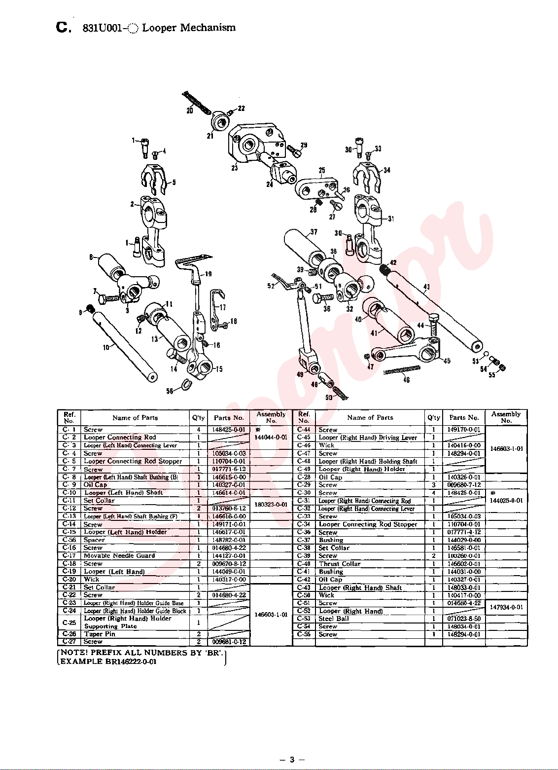
C.
831U001-()
Looper
Mechanism
Ref.
No.
c.
1
Screw
C-2 Looper
C-3 Looper
C-4 Screw
Looper
C-
5
C-
7
Screw
C-8 Looper
C-
9 Oil
C-10
Looper
C-11
Set
C-12
Screw
C-13
Looper
C-14
Screw
C-15
Looper
C-56
Spacer
Screw
C-16
Movable
C-17
C-18
Screw
C-19
Looper
C-20
Wick
C-21
Set
C-22
Screw
C-23
Looper
C-24
Looper
Looper
C-25
Supporting
C-26
Taper
C-27
Screw
NOTE!
(
EXAMPLE
Name
Connecting
(Left
Hand)
Connecting
(Left
Hand)
Cap
(Left
Collar
!f:,eft
Hand)
(Left
Needle
(Left
Collar
(Right
(Right
(Right
Pin
PREFIX
BR146222-0-0l
of
Parts
Rod 1
Connecting
Rod
Shaft
Hand)
Shaft
Hand)
Guard
Hand)
Hand)
Holder
Hand)
Holder
Hand)
Plate
ALL
NUMBERS
Stopper
Bushing
Shaft
Bushing
Holder
Guide
Guide
Holder
Lever
(F)
(B)
Base
Block
Q'ty
Parts
4 148425·0-01
~
1
1
105034-0·03
---
1 110704-0-01
1 017771-6-12
1
146615-0-00
1
140327-0-01
1
146614-0-01
1
2
013760-6·12
---
1
\
146616-0-00
1
149171-0-01
1 146617-0-01
1
148782-0-01
1
014680-4-22
1 144127-0-01
2 009670-8-12
1
144049-0-01
1
140317-0-00
1
2
014680·4·22
---
1
1
---
1
---
~
2
2 009681-0-12
---
BY 'BR·.]
No.
Assembly
No. No. No.
•
144044-0-01
180323-0-01
146603-1-01
Ref.
C-44
C-45
C-46
C·47
C-48 Looper (Right Hand) Holding Shaft
C-49
C-28
C-29
C-30
C-31
C-32
C-33
C-34
C-36
C-37
C-38
C-39
C-40
C-41
C-42 Oil
C-43
C-50
C-51
C-52
C-53
C-54
C-55
Name
of
Parts
Screw
Looper (Right Hand) Driving Lever
Wick
Screw
Looper
(Right
Hand)
Connecting
Connecting
Hand)
Hand)
Holder
Rod
Shaft
Rod
Lever
Stopper
Oil
Cap
Screw
Screw
Looper
Looper
Screw
Looper
Screw
Bushing
Set
Collar
Screw
Thrust
Bushing
Cap
Looper
Wick
Screw
Looper
Steel
Screw
Screw
(Right
Hand)
(Right
Hand)
Connecting
Collar
(Right
(Right
Ball
Q'ty
Parts
149170-0-01
1
1
1 140416-0-00
--
1 148294-0-01
1
1
---
1 140326-0-01
---
009680· 7-12
3
4 148425-0-01
1
1
---
1 105034-0-03
---
110704-0·01
1
017771-4-12
1
1 144029-0-00
1 146581-0-01
2 100260-0-01
146602-0-01
1
144031-0-00
1
1
140327-0·01
1 148033-0-01
140417-0-00
1
1
014680-4-22
1
1 071023-8-50
---
1 148034-0-01
1 148294-0-01
No.
Assembly
146603-1-01
lit
144025-0-01
147934-0·01
-3-
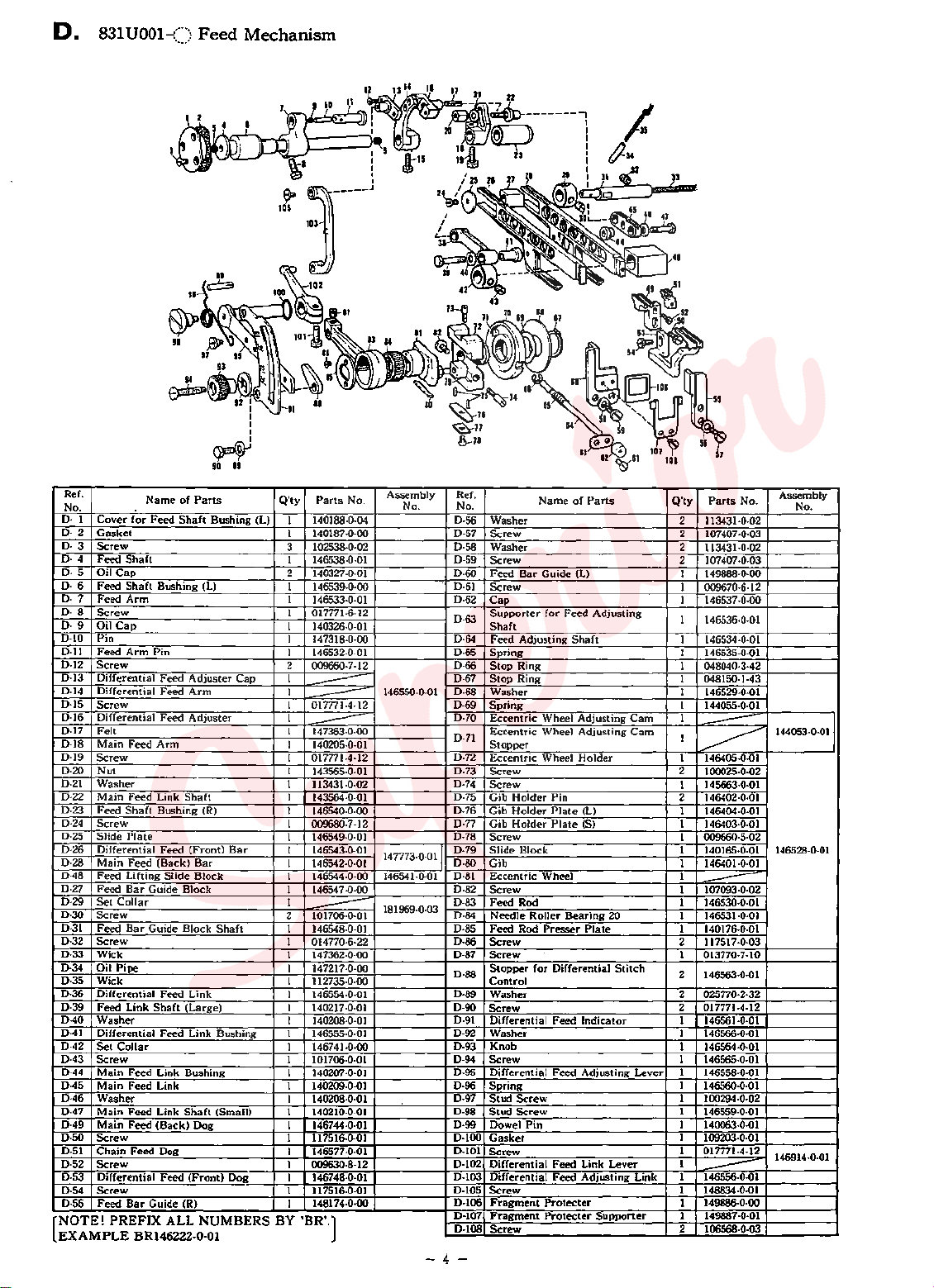
D.
831
UOOl-()
Feed
Mechanism
Ref.
No.
D· 1
Cover
D·
2
D·
3
4
D·
5
D·
D-6 Feed
7 Feed
D·
8
D·
D·
9
D·lO
D·ll
D·l2
D-13
D-14
D-15
D·16
D-17
D·18
D-19
D·20
D·21
D-22
D-23
D·24
D·25
D-26
D·28
D·48
D-27
D-29
D·30
D-31
D·32
D-33
D·34
D-35
D·36
D·39
D-40
D-41
D-42
D-43
D-44
D·45
D-46
D-47
D·49
D-50
D-51
D-52
D-53 Differential
D-54
D-55
NOTE!
EXAMPLE
for
Gasket
Screw
Feed
Shaft
Oil
Cap
Shaft
Arm
Screw
Oil
Cap
Pin
Feed
Arm
Screw
Differential Feed
Differential Feed
Screw
Differential Feed
Felt
Main
Feed
Screw
Nut
Washer
Main
Feed
Feed
Shaft
Screw
Slide
Plate
Differential Feed (Front)
Main
Feed
Feed
Lifting Slide
Feed
Bar
Set
Collar
Screw
Feed
Bar
Screw
Wick
Pipe
Oil
Wick
Differential
Feed Link
Washer
Differential
Set
Collar
Screw
Main
Feed
Main
Feed Link
Washer
Main
Feed
Main
Feed
Screw
Chain
Feed
Screw
Screw
Feed
Bar
PREFIX
BR146222-0-0l
Name
of
Parts
Feed
Shaft
Bushing (L)
Bushing (L)
Pin
Adjuster
Arm
Adjuster
Arm
Link
Shaft
Bushing (R)
(Back)
Guide
Guide
Feed
Shaft
Feed
Link Bushing 1
Link
(Back)
Dog
Feed
Guide (R)
Bar
Bar
Block
Block
Block
Shaft
Link
(Large)
Link Bushing 1
Shaft
(Small)
Dog
(Front)
Dog
Q'ty
Cap
ALL NUMBERS BY 'BR'.
No.
7 -0·00
Assembly
No. No.
146550-0-01
I47773·0·011
146541·0·01
I81969·0-03
Parts
140188-0-04
1
1 140187-0·00
3
102538·0·02
1
146538·0·01
2 140327-0-01 D-60
1
146539-0·00
1
146533·0·01
1
017771·6·12
1
140326-0-01
1
147318-0·00 D·64 Feed
146532-0-01
1
2
009660-7·12
1
1
---
1
017771·4·12
--
1
1
147363·0·00
--
1
140205-0-01
1 017771-4-12
1
143565·0·01
1
113431-0-02
1
143564-0-01
1
146540-0-00
1 009680-7 ·12
1 146549-0·01
1 146543-0·01
1 146542-0·01
1 146544-0·00
1
14654
1
2 101706-0·01
---
1
146548-0·01
1
014770·6·22
1
147362-0·00
1
147217·0·00
1
112735-0-00 Control
146554-0-01
1
1 140217·0·01
1
140208·0·01
146555·0·01
1
146741·0·00
1
101706·0·01
140207-0·0I
1
140209-0-01
1
140208·0·01
140210·0·01
1
1 146744-0·01 D·99
1 117516-0-01
1
146577·0·01
1 009630-8-12
1
146748·0·01
1 117516-0·01
148174·0·00
1
Ref.
D-56
D-57
D-58
D-59
D-61
D-62
D·63
D-65
D-66
D-67
D-68
D-69
D-70
D-71
D-72
D-73
D-74
D-75
D-76 Gib
D-77
D-78
D-79
I
D-80
D-81
D-82
D-83
D-84
D-85
D-86
D-87
D-88
D-89
D-90
D-91
D-92
D-93
D-94
D-95
D·96
D-97
D-98
D-100
D-101
D·102
D-103
D-105
D-106
D-107
D-108
-4-
Cam
Cam
Lever
Link
Q'ty
Name
of
Parts
Washer
Screw
Washer
Screw
Feed
Bar
Guide
Screw
Cap
Supporter
Shaft
Adjusting
Spring
Stop
Ring
Stop
Ring
Washer
Spring
Eccentric Wheel Adjusting
Eccentric Wheel
Stopper
Eccentric Wheel
Screw
Screw
Gib
Holder
Holder
Gib
Holder
Screw
Block 1
Slide
Gib
Eccentric Wheel 1
Screw
Feed Rod I
Needle Roller
Feed Rod
Screw
Screw
Stopper
Washer
Screw
Differential
Washer
Knob
Screw
Differential
Spring
Stud
Screw
Stud
Screw
Dowel
Gasket
Screw
Differential
Differential
Screw
Fragment
Fragment
Screw
(L)
for
Feed
Adjusting
Shaft
Adjusting
Holder
Pin 2
Plate
(L)
Plate
(S)
Bearing
Presser
for
Pin
Protecter
Protecter
Differential
Feed
Feed
Feed
Feed
20 1 146531·0-01
Plate
Stitch
Indicator
Adjusting
Link Lever
Adjusting
Supporter
Parts
No.
2 113431·0·02
2 107407-0.03
2
113431·0-02
2
107407·0-03
1
149888·0·00
1
009670·6·12
1
146537·0·00
146536-0-01
1
1
146534·0·01
1
146535·0·01
048040-3-42
1
1
048150·1·43
1
146529·0·01
1
144055·0·01
1
1
---
~
1
146405-0.01
2
100025·0·02
1 145663·0·01
146402·0·01
1
146404·0·01
1
146403·0·01
1 009660-5-02
140165·0·01 146528·0·01
1
146401·0·01
I I07093·0-02
--
146530·0·01
1 140176-0-01
2 117517-0-03
1 013770·7-10
2
146563·0·01
2
025770·2·32
2 017771-4-12
1
146561·0·01
1
146566·0·01
1
146564·0·01
1
146565·0·01
1
146558·0·01
1
146560·0·01
1
100294·0·02
1
146559·0·01
1
140063·0·01
1
109203·0·01
1
017771·4·12
1
~
1
146556-0-01
1 148834·0.01
1 149886·0·00
1 149887.0-01
2
106568-0-03
Assembly
No.
144053-0-011
146914·0-01
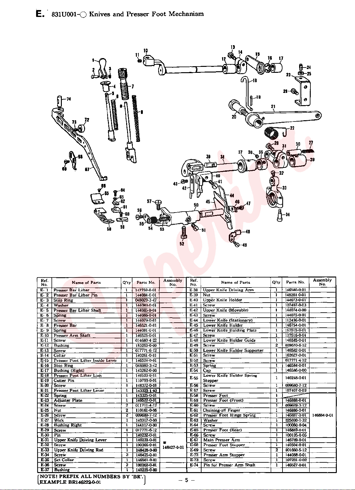
E.
831U001-() Knives
V"
\'"Y
~
18
85
~82
and
r:84
83
Presser
Foot
Mechanism
B--24
Zk~~
28~
e
21
~~
51
58
Q'ty
Parts
No.
140248·0·01
Assembly
No.
NOTE!
[
EXAMPLE
PREFIX
ALL
BR14Q23..0.01
NUMBERS
BY
'BR'.)
146884-0-01
-5-
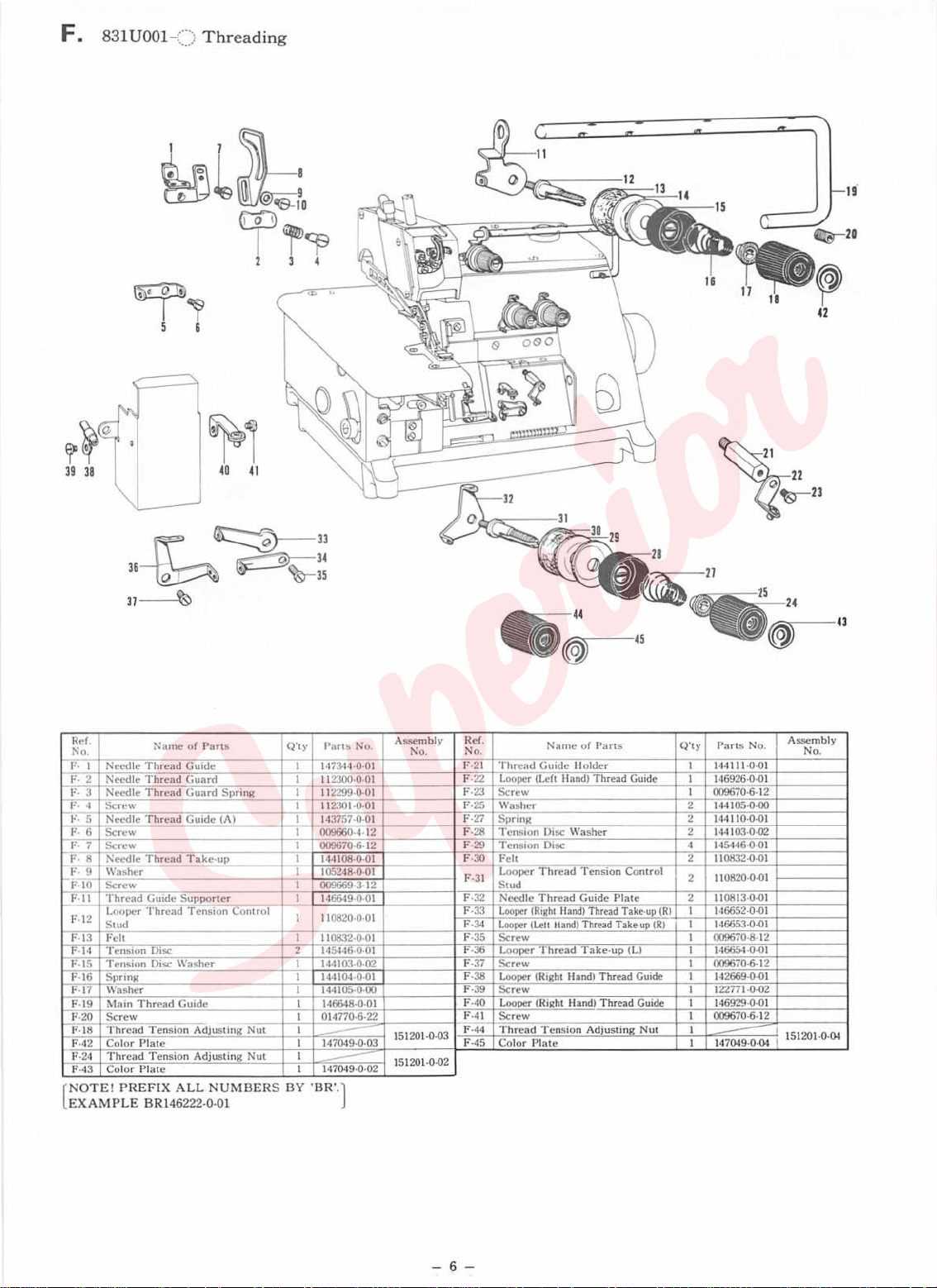
F. 831
UOOl
-()
Threading
~
,
40
41
Re
f.
No.
I
F·
F· 2
3
F·
--v:--4
F- 5
F· 6 Sc re w I 009660·4· 12
t-F
. 7
F·
8
I-p
: 9
F-
10
IJ:.JI .
F-12
F-13 Fe
F·l4
-·
15
F
f..
f6
F-17 Washer I
F-19
F-
20 Screw
F-18 Thre
F-42 Color Pl
F-24 Thread Tension
F-43 Color
NOT E!
[
EXAMP
Name of Parts
Needle Thread
dle Thread Guard
Nee
Need
le Thr
Sc
rew I
Needle
Sc
rew I 009670-6-12
Needle
Washer I
Sc
rew I
T hread Guid
L
ooper Thread
Stud
lt
Tensi
on Disc
T
ens
ion Disc Was
Sp
ring I 144104·0·01
Main
Thread Guide I 146648-0-01
ad Ten
PREF
LE
Guide
ead
Guar
d S
prin
Thread G
Thread
Plat
uid
e
(A)
T a ke-up I 14•1108·0·01
e Supporter I
T ens io n Coot
her
sion
Adjusti
ate
e I 147049·0·02
ng Nut I
Adjusting
IX ALL NUMB
BRl4
6222
-0-01
Q't
g I
rol
Nut I
ERS
BY '
y
Parts No.
I 14734
I
I
I
I
2 145446-0-01
I 1
4·0·
112300·0
112299·0·0 I
112301·0·01
14
3757·0·01
105248·0·01
009669·3· 12
14
6649·0·01
11
01!20·0·01
11
0832·0·01
44
103·0·02
144105·0·
I
01
4770·6-22
I 147049-0-03
--
--
BR'.)
01
·0
1
00
A
sse
mbly Ref.
No.
151201·0·03
151201·0·02
Nam
No
.
F-21
Thread Guid
Looper (Left
F-22
F-23
Sc
rew I
Washer
F-25
F-27 Spri
F-28
F-29
F-30
F-31
F-32 Needle
F-33 L
F-34 Looper
F-35 Scre w I 009670·8· 12
F-36
F-37 Scre w I 009670-6- 12
F-38
F-39 Screw I 122771·0·02
F-40 Looper (Right Hand) Threa
F-41 Screw
-
FF-45
ng
Tension Disc Was
Tension Disc
Fe
lt
L
ooper Thread
St
ud
ooper (Right
L
ooper Thread
Loo
per (Ri
44
Thread Tension
Co
lor Plate I
e of Parts
e Ho lder I 144111·0·01
II and)
Thread Guide
her
Ten
sion Contr ol
Thread
Guide Plat
Hand) T
hread
(Lett
Hand)
ght Hand) Thread Guide I 142669·0·01
Take-up (RI I 146652
Thread Take-up (R) I 146653·0·01
T a
ke-u
p (L)
d Guide I 146929·0·01
Adju
stin
S<
Q'
ty Parts No.
I
14
692
6·0
009670·6· 12
2 144105·0·
2
14411
2 144103·0·02
4 145446·0·01
2 110832·0·01
2
e 2 110813·0·01
I
I 009670·6·12
Nut
I
0·0·
110820·0·
14
6654 .o.OJ
14
7049·0·04 I 151201·0·
-
-0-0
·01
00
01
01
ssembly
A
No
.
1
04
-6
-
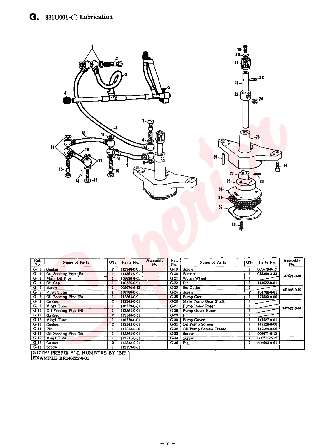
G.
831
UOOl-()
u
Lubrication
••-1
2oa.
21.
~2
Ref.
No.
G· 1
Gasket
Oil Feeding Pipe (B)
G·2
3 Main Oil
G·
G-
4
Oil
Screw
5
G·
Vinyl
G·
6
Oil Feeding
G-
7
G-
8
Gasket
9 Vinyl
G·
Oil
G·10
G·ll
Gasket
G-12 Vinyl
G-13
Gasket
G-14
Pin
Oil Feeding Pipe (B)
G-15
G-16 Vinyl
G-17
Gasket
G-18
Screw
NOTE!
(
EXAMPLE
Name
Pipe
Cap
Tube
Pipe
Tube
Feeding
Pipe
Tube
Tube
PREFIX
BR146222-0-0l
of
Parts
(B)
(B)
ALL
NUMBERS BY
Q'ty
Parts
2 112348·0·01
112364;0·01
1
1 146636-0·01
1 140325-0-01
1
009670·6-12
1 140780-0·01
1
112364-0-01
2
112348-0-01
1
140779-0·01
1
112364-0-01
2
112348-0-01
1 140778-0-01
2 112348-0-01
1
147318-0·00
1
112364-0-01
1
147211·0·01
2
112348-0·01
1
112359-0·01
'BR'.]
No.
Assembly
No. No.
Ref.
G-19
G-20
G-21
G-22
G-23
G-24
G-25
G·26
G-27
G-28
G-29
G-30
G-31
G-32
G-33
G·34
G-35
Name
Screw
Washer
Worm Wheel
Pin
Set
Collar
Screw
Pump
Case
Main
Pump
Pump
Inner
Pump
Outer
Pin
Pump
Cover
Oil
Pump
Pump
Screen
Screen
Oil
Screw
Screw
Pin
of
Gear
Roter
Roter
Parts
Shaft
Frame
Q'ty
Parts
009670·8·12
1
1
025350·3·32
1
1 144622-0-01
-----
1
2
101706-0-01
---
1 147522-0-00
1
1
1
-----
---
1
1 147527-0-01
---
---
1
147528-0-00
1
147529-0-00
3 009671-0-12
2 009711-2-12
2
508693-0-01
No.
Assembly
No.
147521-0-01
181995-0·011
147523-0-01
-7-
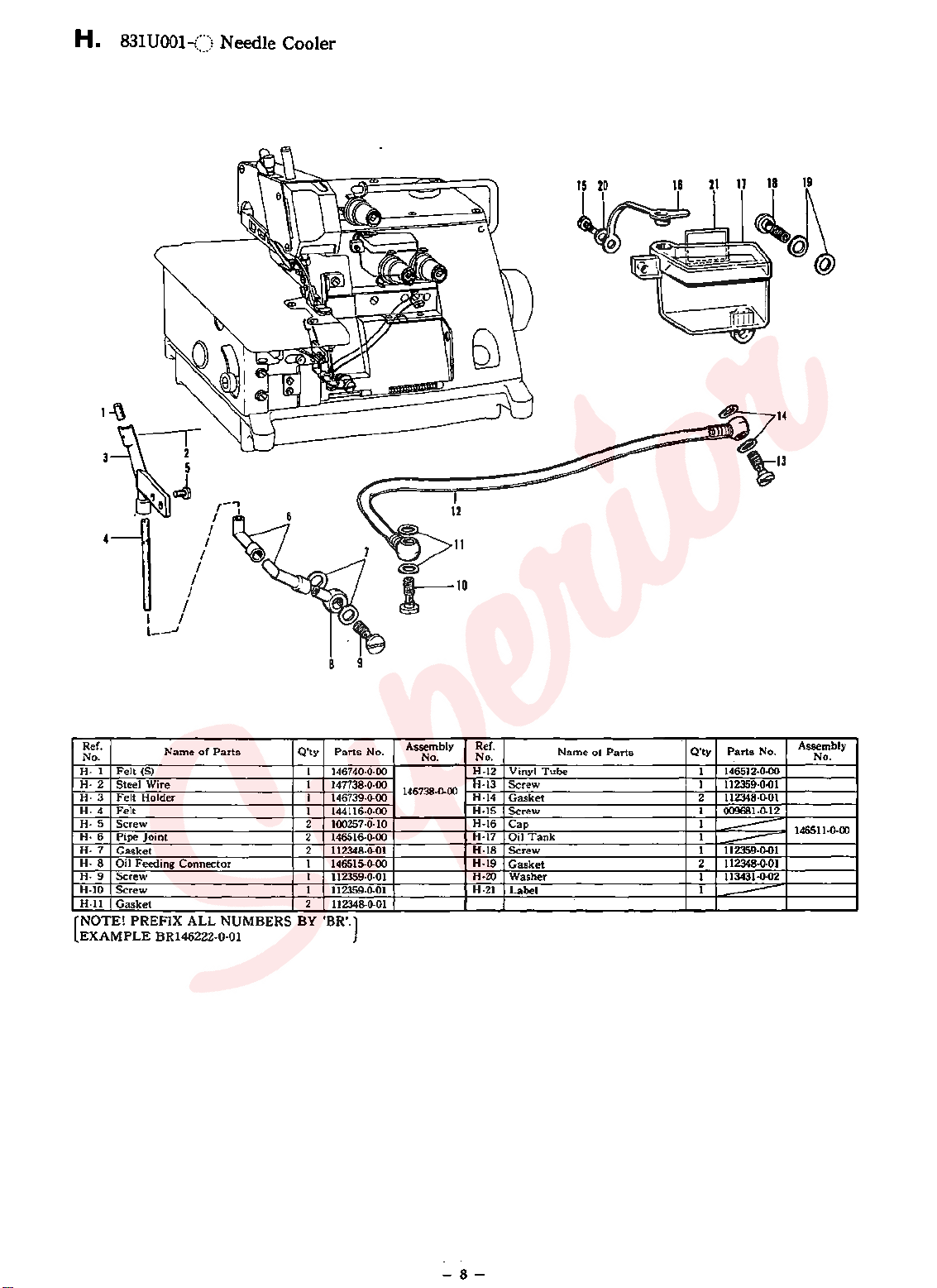
H.
831
UOOI-{) Needle Cooler
Ref.
No.
H·
1
H-2
H·
3
H·
4
H· 5 Screw
H-6
H·
7
H-8
H- 9
H-10
H-11
NOTE!
[
EXAMPLE
Name
of
Parts
Felt
(S)
Steel Wire 1
Felt
Holder
Felt
Pipe
Joint
Gasket
Oil Feeding
Screw
Screw
Gasket
PREFIX
Connector
ALL
BR146222-0-0l
Q'ty
Parts
1 146740·0·00
147738-0-00
1 146739-0-00
1 144116-0-00
2 100257-0·10
2 146516-0.00
2
112348-0-01
1 146515-0-00
1 112359-0.01
1
112359·0.01
2
112348-0.01
NUMBERS BY 'BR'.)
r·o
Assembly
No.
146738-0-00
No.
Ref.
No.
H·12
H-13
H-14
H-15
H-16
H-17
H-18
H-19
H-20
H-21
Vinyl
Screw
Gasket
Screw
Cap
Oil
Tank
Screw
Gasket
Washer
Label
Tube
Name
ot
Parts
Q'ty
Parts
1 146512·0·00
112359-0.()1
1
2
112348-0-01
1 009681-0-12
1
~
1
112359-0.01
1
112348-0-01
2
----
1 113431·0·02
1
----
No.
Assembly
No.
146511-0-00
8
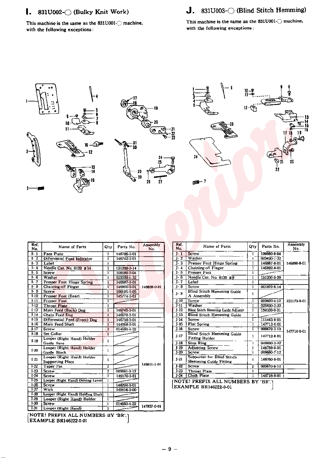
I.
831U002-()
This
machine
with
the
is
the
following
(Bulky
same
as
exceptions
Knit
the
831U001{)
:
Work)
machine,
J.
This
with
831
U003-()
machine
the
following
is
the
(Blind
same
as
exceptions
Stitch.
the
831U001<:) machine,
:
Hemming)
~4
i-5
s-&
9----4?
~7
to-O~
11~
~~
~
~13
~II
3--
Ref.
No.
J. 1
J.
2
J.
3
J.
4
J.
5
J. 6
J.
7
I·
8 Chaining-off
I· 9
1·10
1-11
1-12
1-13
1-14
1·15
1·16
1-17
1-18
1·19
1·20
1·21
1·22
1·23
1·24
1-25
1-26
1-27
1-28
1-29
1-30
1-31
NOTE!
[
EXAMPLE
Name
of
Parts
Face
Plate
Differential
Label
Needle
Screw
Washer
Presser
Screw
Presser
Presser
Throat
Main
Chain
Differential
Main
Screw
Set
Looper (Right
Guide
Looper (Right
Guide Block
Looper (Right Hand)
Supporting
Taper
Screw
Screw
Looper (Right Hand) Driving Lever
Screw
Wick
Looper (Right Hand) Holding Shaft
Looper (Right
Screw
Looper
Feed
Cat.
No. 6120 #
Foot
Foot
Foot
Plate
Feed
(Back)
Feed
Dog
Feed
Feed
Shaft
Collar
Base
Plate
Pin
(Right
PREFIX
BR146222·0-01
Indicator
Hinge
Spring
Finger
(Rear)
Dog 1
(Front)
Hand)
Holder
Hand)
Holder
Holder
Hand)
Holder
Hand)
ALL
NUMBERS
14
Dog
a
14
~11
~19
Q'ty
Parts
1 146706-0-01
1 146742-0-01
1
1
151200-0-14
1 100080-0-04
1 025030-1-32
1 146887-0-01
1 146900·0·01
1 100105-0-05
1
145774-0·01
1
1
--
146745-0-01
1
146578-0-01
1 146750-0-01
1 144068-0-01
2 014680·4·22
1
~
1
~
1
~
1
~
2
2
009681-0·12
---
1
149170-0-01
1
~
1
148294-0-01
1
140416-0-00
1
~
1
~
1
014680·4·22
__.;::::;:;:=-
1
BY
'BR'.)
No.
.
.
20
~~~
~23
241
25
29
,~~
28
26
21
Assembly
No.
146898-0-01
146611·1·01
147937-0-01
1-f
4
...
~~
5
.·
~
---1
Ref.
No.
1·
1
1·
2
J·
3
1·
4
J.
5
J·
6
J·
7
J·
8
J·
9
HO
J-11
J-12
J-13
J·14
J-15
J-16
1·17
1·18
J-19
1·20
J·21
J-22
J-23
1·24
NOTE!
[
EXAMPLE
Name
Screw
Washer
Presser
Foot
Chaining-off
Presser
Foot
Needle
Cat.
Label
Screw
Blind
Stitch
A Assembly
Screw
Washer
Blind
Stitch
Blind
Stitch
Screw
Flat
Spring
Screw
Blind
Stitch
Fitting
Holder
Stop
Ring
Adjusting
Screw
Supporter
Hemming
Screw
Throat
Plate
Cloth
Plate
PREFIX
BR146222·0-01
Hemming
Screw
for
Guide
\-8
~
of
Parts
Hinge
Spring
Finger
No. 6120
Hemming
Guide
Hemming
Hemming
Blind
Fitting
ALL
NUMBERS
#9
Guide
Adjuster
Guide 1
Guide
Stitch
9 8
ll=~L~
12~---
" .
--
~13
l=
~15
11 18
19
~~Jq
~21
20
22
Q'ty
Parts
1 100080-0·04
1 025030-1-32
1
146887·0·01
1 146892-0-01
1
1 151200-0-09
---
1
1 001670-6-14
1
~
009660-4-12
1
1 025030-2-32
1 150339-0-01
1 111443-0-01
---
1 147713-0-01
009679-3-12
1
147712-0-01
1
1
048030-3-42
1 146759-0-01
1 009680-7-12
1 146760-0·01
2
009670·6·12
1
1 146716·0·01
BY
'BR'.]
No.
Assembly
No.
146890-0-01
151173·0·01
147710-0-01
14
16
-9-
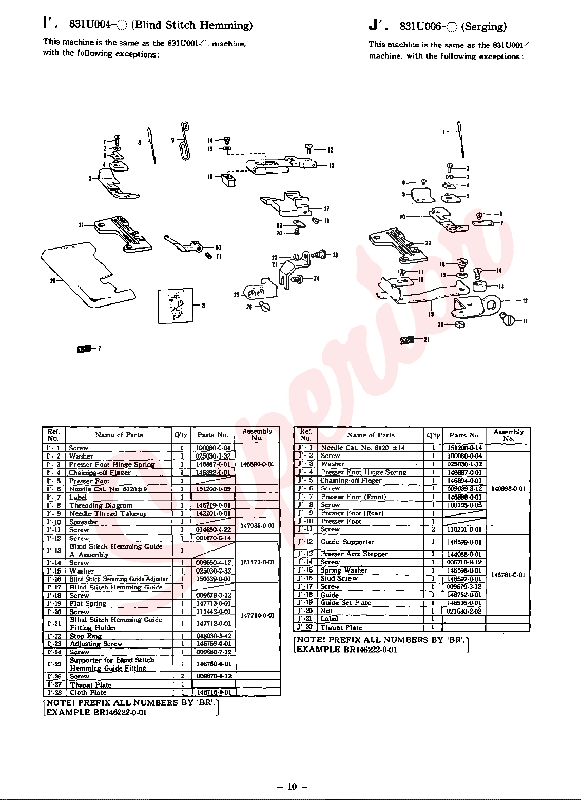
I •
I
This
with
831
U004-()
machine is
the
following exceptions :
the
(Blind
same
II~
Stitch
as
the
831UOOI<) machine,
~10
Hemming)
'-11
831
J
'.
This
U006-()
machine is
machine, with
the
the
(Serging)
same
as
following
the
831
UOOI
exceptions:
-:::::.
--1
Ref.
No.
I'· 1 Screw
I'·
2
I'·
3
I'·
4
I'·
5
I'·
6
I'·
7
I'·
8
J'. 9
1'-10
1'-11
1'-12
1'-13
1'·14
I'
-15
1'-16
1'·17
1'·18
1'·19
1'·20
1'·21
1'·22
t·23
1'·24
1'·25
1'·26
1'·27
1'·28
NOTE I PREFIX
(
EXAMPLE
Name
of
Washer
Presser
Foot
Chaining-off
Presser
Needle Cat. No.
Label 1
Threading
Needle
Spreader
Screw
Screw
Blind
A Assembly
Screw
Washer
Blind
Blind.
Screw
Flat
Screw
Blind
Fitting
Stop
Adjusting
Screw
Supporter
Hemming
Screw
Throat
Cloth
Hinge
Finger
Foot
6120#9
Diagram
Thread
Take-up
Stitch
Hemming
Stitch
Hemming
Stitch
Hemming Guide
Soring 1
Stitch
Hemming
Holder
Ring
Screw
for
Blind
Guide Fittil'lg_
Plate
Plate
ALL
BR146222-0.0l
Parts
S~ing
Guide
Guide
Adjuster
Guide
Stitch
NUMBERS BY
Q'ty
Parts
1 100080·0·04
02503().1·32
1
1 146887·0·01
1 146892·0·01
1
1 151200-0-09
--
1 146719-0·01
1 142201·0·01
1
1
014680·4·22
--
001670·6·14
1
1
~
1 009660·4·12
1
025030·2·32
1
150339·0·01
1
1 009679·3-12
---
147713·0·01
1 111443·0·01
147712-0-01
1
1 048030·3·42
1
146759·0·01
1 009680-7·12
1 146760·0·01
2 009670-6-12
1
146716-0-01
1
'BR'.)
No.
Assembly
No.
146890·0-01
147935-0-01
151173·0·01
147710-0-01
Ref.
No.
0
]'
1
1'·2
J'·
3
]'·
4
1'· 5
]'·
6
1'· 7
]'·
8
]'·
9
]'·10
J'·ll
]'·12
]' ·13
J'
·14
]'·15
]'·16
1'·17
J' ·18
J'
·19
]'·20
]'·21
]'·22
NOTE!
[
EXAMPLE
N arne of
Needle Cat. No.
Screw
Washer
Presser
Foot
Chaining·off Finger
Screw
Presser
Screw
Presser
Presser Foot
Screw
Guide Supporter 1
Presser
Screw
Spring Washer
Stud
Screw
Guide
Guide
Nut
Label
Throat
PREFIX
Hinge Spring
Foot
(Front)
Foot
(Rear)
Arm
Stopper
Screw
Set
Plate
Plate
ALL NUMBERS BY 'BR'.)
BR146222·0·01
Parts
6120 #
14
Q'ty
Parts
No.
1
151200·0·14
1
100080·0·04
1
025030·1·32
1
146887·0·01
1
146894-0.()1
1
009639·3·12 146893·0·01
1
146888·0.01
1
100105·0·05
1
1
---
2
110201.0·01
---
146599·0·01
1
144088·0·01
1
005710·8·12
1
146598·0·0 1
1
146597·0·01
1
009679·3·12
1
146762·0·01
1
146596·0·01
1
021680·2·02
1
1
Assembly
No.
146761·0·01
-
10-
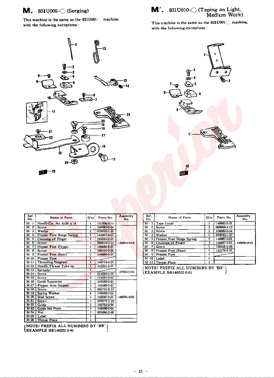
M.
This
with
831
U005-()
machine is
the
following
the
same
exceptions:
(Serging)
as
the
831UOOI-::::
machine.
M'
This
with
.
831
U010:.·{)
machine is
the
following
the
same
exceptions:
(Taping
Medium
as
the
831
on
Light,
Work)
UOOI-::::::.
machine,
\'
ln
l--2
@----3
~4
5
~
IL~
·~~~~
~
13
·--14
~--=-·
...
26
20
!f-=::
~17
6
~~~
23
~
24~
~15
10
-
Ref.
No. No.
M-
1
2
M-
M· 3 Washer
M·
4
M·
5 Chaining-off
M· 6 Screw
M·
7
M·
8
M·
9
M-10
M·ll
M-12
M-13
M-14
M-15
M-16
M-17
M-18
M-19
M-20
M-21
M-22
M·23
M·24
M-25
M-26
NOTE!
(
EXAMPLE
Name
of
Parts
Cat.
Needle
Screw
Presser
Presser
Screw
Presser
Presser
Threading
Needle
Spreader
Screw
Screw
Guide
Presser
Screw
Spring
Stud
Screw
Guide
Guide
Nut
Label 1
Throat
No. 6120 #
Foot
Foot
Foot
Foot
Diagram
Thread
Supporter
Arm
Washer
Screw
Set
Plate
Plate
PREFIX
BR146222-0-0l
Hinge
Finger
(Front)
(Rear)
Stopper
ALL
14
Spring
Take-up
NUMBERS BY
Q'ty
Parts
1 151200-0-14
1 100080-0·04
025030·1·32
1
1 146887·0·01
146894-0-01
1
1
009639·3·12 146893·0·01
1
146888·0·01
1
100105·0·05
146889·0·01
1
1
1 146719·0·01
1 142201·0·01
----
1
1 014680-4-22
--
2 110201·0·01
1
146599·0·01
1
144088·0·01
1 005710-8·12
1
146598·0·01
1 146597 ·0·01 146761·0-01
1
009679·3·12
1
146762·0·01
1 146596-0·01
1 021680·2·02
1
'BR'.)
No.
Assembly
147935·0·01
Ref.
No.
M'· 1 Tape
M'·
2
Screw
M'· 3 'Screw
M'·
4
Washer
M'· 5 Presser
M'·
6
Chaining-off
M'·
7
Screw
M'· 8 Presser
M'·
9
Presser
M'-10
Label
M'·ll
Throat
NOTE!
[
EXAMPLE
Q'ty
Name
of
Parts
Guide 1 146883·0·01
Foot
Hinge
Spring
Finger
Foot
(Rear)
Foot
Plate
PREFIX ALL NUMBERS BY 'BR'.)
BR146222-0-0l
Parts
2
009669·4·12
1
100080-0-04
1 025030-1-32
1
146887
1 146897-0-01
1 100105-0-05
145774-0-01
1
1
-=----
1
1
No.
·0-0 1
Assembly
No.
146895-0-01
-11-
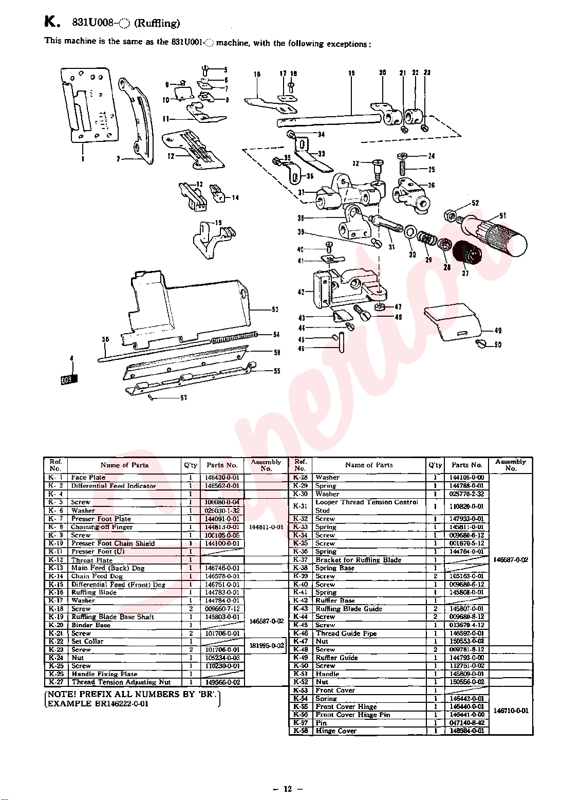
K. 831 UOOB-() (Ruffling)
This
machine is
the
same
as
the
831UOOI<) machine, with
the
following
exceptions:
Ref.
No.
K· 1
K-2
K·
4
K·
5
K·
6
K·
7
K·
8
K·
9
K-10
K·ll
K-I2
K-I3
K-14 Chain Feed Dog 1
K-15
K-16
K-17
K-18
K-19 Ruffling Blade
K·20
K-21
K-22
K-23
K·24
K·25
K·26
K-27
(NOTE!
EXAMPLE
N arne
of
Parts
Face
Plate
Differential
Screw
Washer 1
Presser
Chaining-off
Screw
Presser
Presser
Throat
Main Feed (Back) Dog
Differential
Ruffling Blade 1
Washer 1
Screw
Binder Base I
Screw
Set
Screw
Nut
Screw
Handle Fixing
Thread
Feed
Indicator 1
Foot
Plate
Finger
Foot
Chain Shield 1
Foot
(U)
Plate
Feed
(Front) Dog
Base
Shaft
Collar 1
Plate
Tension
PREFIX
Adjusting
ALL NUMBERS BY 'BR'.)
Nut
BR146222·0·01
Q'ty
Parts
1 146430·0·01
I46562·0·01
I
I
IOOOB0-0-04
025030·1·32
1
144091-0-01
I
1448I3·0-01
I
100105-0-05
144100·0·01
1
1 K-37
----
1
I46746·0·0I
146578-0-0I
1
14675I-0-01
I44783·0·0I
I44784·0·01
2
009660·7·12
I
I45803·0·0I
2 101706-0-0I
----
2 10I706-0-01
-----
1
105234-0-03
1
110230-0-01
I
1
149566-0-02
---
Assembly Ref.
No.
I4481l·O·OI
I46587·0·02
I81995·0·02:
No.
Q'ty
Name
of
No. No.
K-28
Washer
Spring
K·29
K-30 Washer
Looper
K·3I
K-32
K-33
K-34
K-35
K·36
K·38
K-39
K-40
K·4I
K-42
K-43
K·44
K-45
K-46
K-47
K-48
K-49
K·SO
K·51
K·52
K·53
K-54
K-55
K·56
K·57
K·SS
Thread
Stud
Screw
Spring
Screw
Screw
Spring
Bracket
for Ruffling Blade
Spring
Base
Screw
Screw I 009680·6·I2
Spring
Ruffler
Base
Ruffling Blade Guide 2 I45807 -0·0 I
Screw
Screw
Thread
Guide Pipe
Nut
Screw
Ruffler Guide 1 144793·0·00
Screw
Handle
Nut
Front
Cover
Spring
Front
Cover
Front
Cover
Pin
Hinge Cover 1
Parts
Tension Control
Hinge 1
Hinge Pin
Parts
1 144105·0·00
1 144788-0·01
1 025770·2·32
1 110820-0.01
147933-0-01
1
1 I45811-0·0I
I
009680·6·I2
I
OOI670·5·I2
I I44764-0.0I
I
I
2 105I63·0·01
---
·------
1 I45808·0-0I
1
009680-8-I2
2
---
OI3679-4·I2
1
1 146592·0·01
I50553-0.02
1
2 009781·8·12
11275I·0-02
1
145809-0-01
1
1 150556·0-02
1
1 146442-0.01
14644().0.01
------
146441-0.00
1
04714().8..42
1
148984-0-01
No.
Assembly
I46587 ·0·02
146710.0.01
-
12-
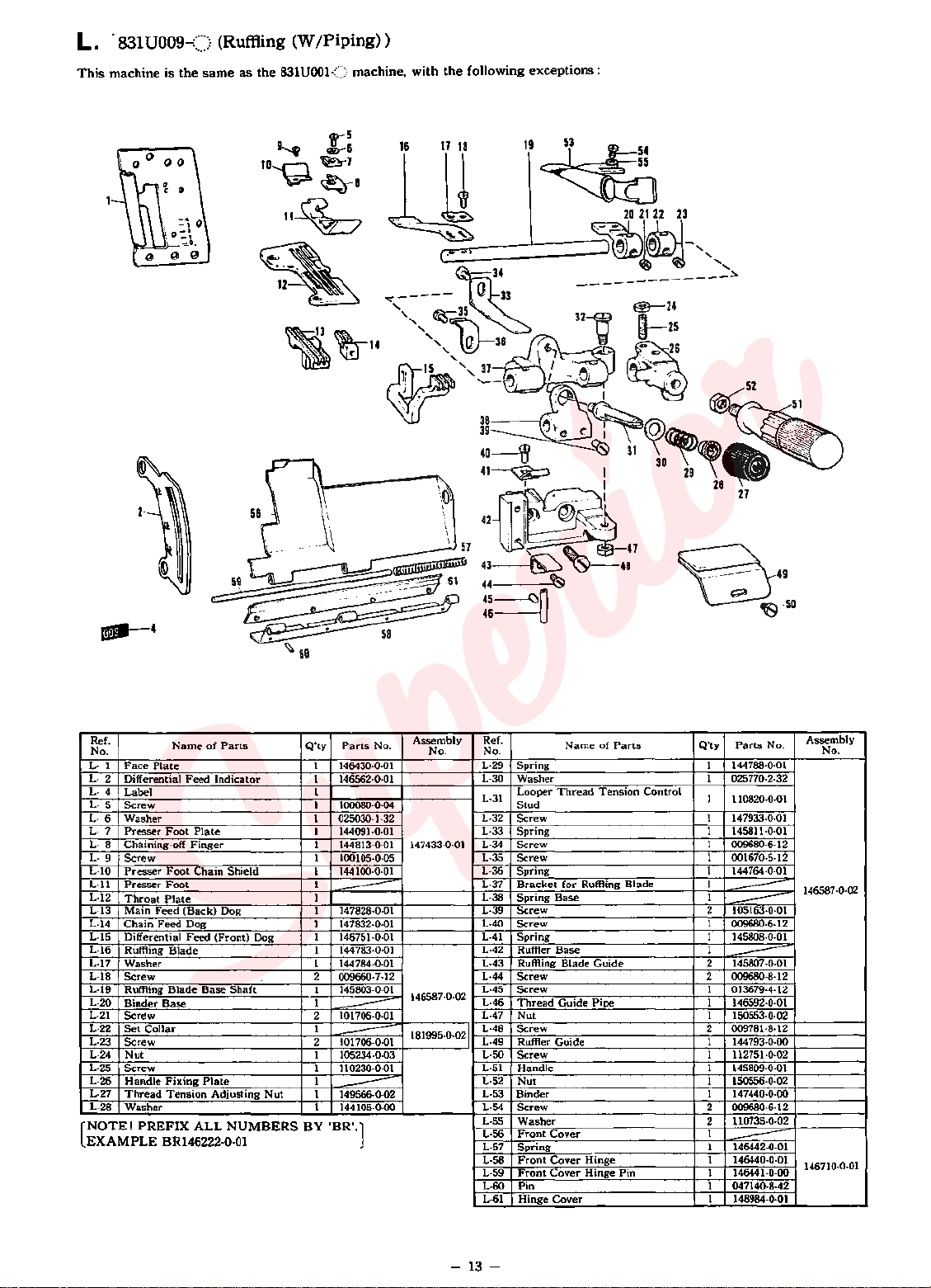
L.
This
·
machine is
831U009-()
the
same
(Ruffling (W
as
the
831U001{)
/Piping))
machine,
with
the
following
exceptions:
--4
Ref.
No.
L-1 Face
L-
L-
L-
L· 6
L·
L·
L-9 Screw
L-10
L·ll
L-12
L-13
L-14
L-15 Differential
L-16
L-17
L-18
L-19 Ruffling
L-20
L-21
L-22
L-23
L-24
L-25
L-26
L-27
L-28
[NOTE!
EXAMPLE
2
Differential
4
Label
5
Screw
Washer
7
Presser
Chaining-off
8
Presser
Presser
Throat
Main
Chain
Ruffling
Washer
Screw
Binder
Screw
Set
Screw
Nut
Screw
Handle
Thread
Washer
Plate
Foot
Foot
Foot
Plate
Feed
Feed
Blade
Blade
Base
Collar
Fixing
Tension
PREFIX
BR146222-0-01
Name
of
Parts
Feed
Indicator
Plate
Finger
Chain
Shield
(Back)
Dog 1
Dog 1
Feed
(Front) Dog 1
Base
Shaft
Plate
Adjusting
ALL
Nut
NUMBERS
Q'ty
Parts
1
146430·0·01
1
146562·0·01
1
1
1 00080·0·04
025030-1-32
1
1 144091·0·0 1
1
144813·0·01
1
100105·0·05
1 144100-0-01
1
1
---
147828·0·01
147832·0·01
146751·0·01
1 144783·0·01
144784-0·01
1
2 009660·7-12
145803-0-01
1
1
101706·0·01
2
----
1
101706-0-01
2
---
1 105234·0-03
1 110230·0·01
1
1
149566·0·02
1 144105-0-00
----
BY
'BR'.]
No.
Assembly
No. No.
147433·0·01
146587-0-02
181995-0-021
Ref.
L-29
L·30
L-31
L-32
L·33
L-34
L-35
L-36
L-37
L-38
L-39
L-40
L-41
L-42
L-43
L-44
L-45
L-46
L-47
L-48
L-49
L-50
L-51
L-52
L-53
L-54
L-55
L-56
L-57
L-58
L-59
L-60
L-61
Binder
Name
of
Parts
Spring
Washer
Looper
Thread
Stud
Screw
Spring
Screw
Screw
Spring
Bracket
Spring
Screw
Screw
Spring
RutHer
Ruffling
Screw
Screw
Thread
Nut
Screw
RutHer Guide 1
Screw
Handle
Nut
Screw
Washer
Front
Spring
Front
Front
Pin
Hinge
Tension
for
Ruffling
Base
Base
Blade
Guide
Cover
Cover
Cover
Cover
Blade
Guide 2 145807 ·0·0 1
Pipe
Hinge
Hinge
Pin
Control
Q'ty
Parts
144788·0·01
1
1 025770·2·32
1
110820·0·01
1 147933·0-01
1
145811·0·01
1
009680-6-12
001670-5-12
1
1
144764·0·01
1
1
---
2
105163-0·01
---
1 009680-6-12
1 145808-0-01
1
---
009680·8·12
2
1 013679-4-12
1 146592·0·01
1 150553-0-02
2
009781·8·12
144
793·0·00
1
112751·0·02
145809-0-01
1
1 150556·0·02
1
147440·0·00
2
009680·6·12
110735·0-02
2
1
1 146442·0·01
----
1 146440-0-01
1 146441·0·00
1 047140-8-42
1 148984-0-01
No.
Assembly
No.
146587·0·02
146710·0·01
-
13
-
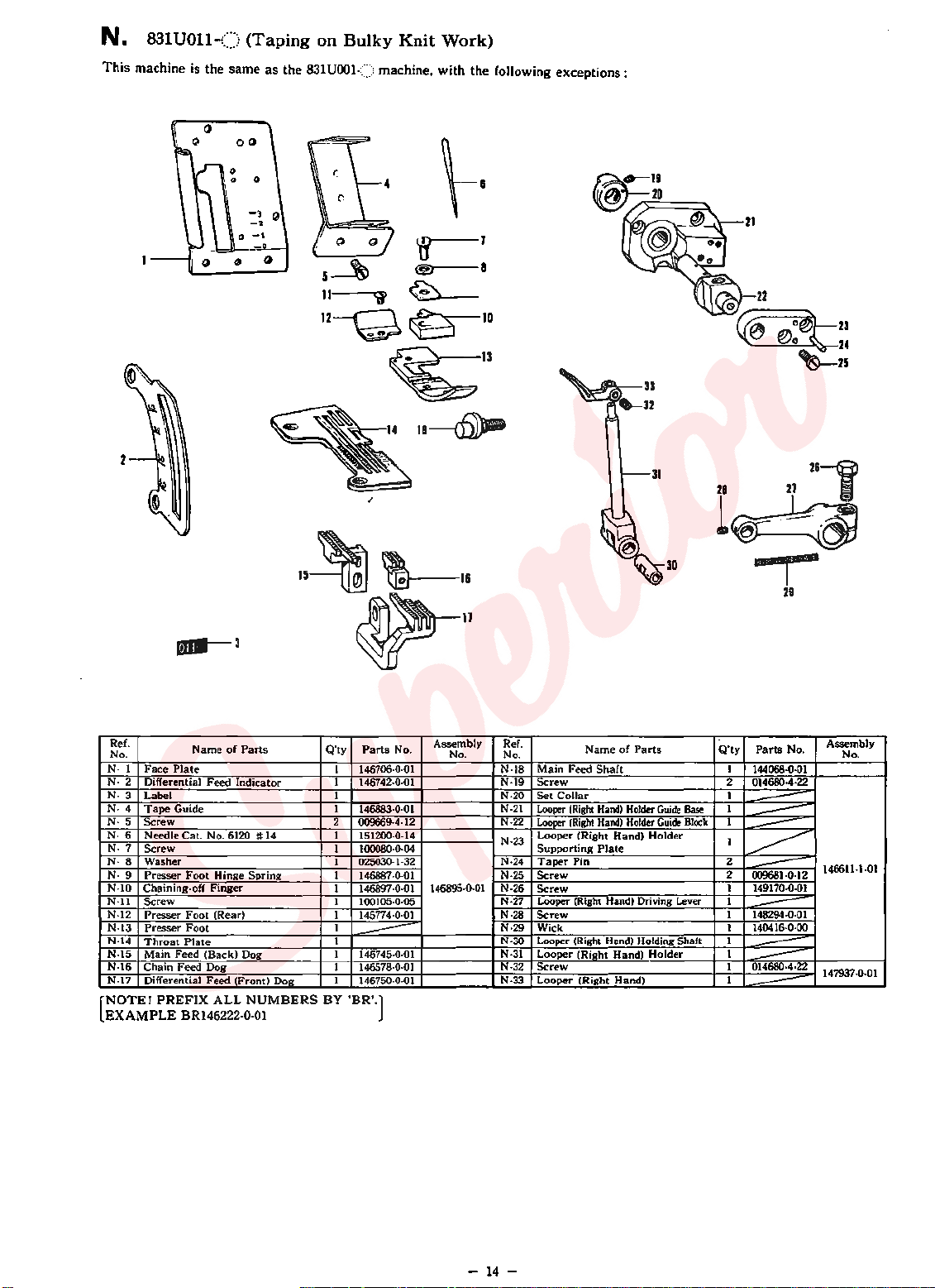
N.
831
This
machine is the
UOll-()
(Taping
same
as
on
Bulky
the
831UOOI<:>
12--Q~
Knit
Work)
machine, with
the
w-1
@)
~
~13
18
---cfil)Jmi
8
10
following
exceptions:
26--@
-
Ref.
No.
N· 1
N- 2
N- 3 Label
N- 4
N-5 Screw
N·6
N·7
N·8
N- 9
N·10
N·ll
N·l2
N-13
N-14
N·15 Main Feed (Back) Dog
N-16 Chain
N·17 Differential
NOTE!
[
EXAMPLE
Name
of
Face
Plate
Differential
Tape
Needle Cat. No. 6120 #
Screw
Washer
Presser
Chaining·off
Screw
Presser
Presser
Throat
Feed
Guide
Foot
Foot
Foot
Plate
Feed
Dog
Feed
PREFIX
BR146222-0-01
Indicator
Hinge
Finger
(Rear)
(Front) Dog
ALL NUMBERS BY
Parts
Spring
15~~11
~11
Q'ty
Parts
146706-0-01 N-18
1
146742-0-01
1
I N-20
I
146883·0·01
2
14
009669·4·12
151200·0-14
1
1
100080·0·04
1
025030·1·32 N·24
1
146887-0.01 N·25
1 146897·0·01 146895·0·01 N·26
1
100105·0·05
1
145774·0·01
1
I N·30
--
1 146745-0·01
1 146578·0·01
1
146750-0-01
'BR'.]
No.
Assembly
No.
Ref.
No.
N·19
N-21
N-22
N·23
N·27
N-28
N·29
N-31
N-32
N-33
Name
Main
Feed
Collar
(Right
(Right
Pin
Shaft
Hand)
Hand)
Plate
Screw
Set
Looper
Looper
Looper (Right Hand)
Supporting
Taper
Screw
Screw
Looper (Right Hand) Driving Lever
Screw
Wick
Looper (Right Hand) Holding Shaft
Looper (Right Hand)
Screw
Looper (Right Hand)
of
Holder
Holder
Parts
Holder
Holder
Guide
Guide
r~
.,-
29
Q'ty
Parts
No.
I
144068-0·01
2
014680·4·22
1
1
Base
Block
---
1
---
1
---
~
2
2
009681-0·12
---
1 149170·0·01
1
1 148294-0·01
---
1
140416·0·00
1
1
---
1 014680·4·22
---
1
---
Assembly
No.
146611-1·01
147937·0·01
-
14-
 Loading...