

Singer 591UTT Service Manual

SINGER
591
UTT
Service
Manual
CONTENTS
Page
No.
Description
UnderbedThread Trimmer
Principal
Descriptionof TrimmingOperation
Timing and Setting
Parts
DriveSystem of Thread Trimmer 2
Pullingand TrimmingUnit 2
Tension Releaseand MovableSlack Thread Regulator 3
Adjustment of Needle Stop Positions
Timing—ActuationofTrimmer Solenoid 8
Timing —CompletionofActuationofTrinuner Solenoid
SettingofTrimmer Solenoid 9
SettingofStationary Knife 9
SettingofThread Puller
AdjustmentofPressureofThread Puller Against Stationary Knife
Timing and Setting of Thread Puller Action Cam
TimingofTension Release ActionCam 12
SettingofThread PuUerAction Cam Adjusting Plate 13
AdjustmentofGap Between Tension Discs
TimingofTension Release 14
Adjusting the LengthofNeedle Thread End
AdjustmentofThread Wiper 15
1
2-15
2-3
3-6
6-15
6-8
8-9
9-10
10-11
11-12
13-14
14-15
Back
Tack
Device
Principal Parts
Description of BackTacking Operation 18
Setting and Adjustment
of
BackTack Device
SettingofBack Tack Solenoid 18
SettingofFeed Rock Shaft DrivingFrame 19
Setting
of
Feed Rock Shaft DrivingFrame Action Shaft and Collar 19
SettingofFeed Rock Shaft DrivingFrame Action Lever
Feed Rock Shaft Driving Frame Spring Tension 20
Setting of Feed Rock Shaft Driving Frame Stopper Spring 20
SettingofPush
Button
Switch 20
AdjustmentofPush Button Spring Tension 21
Cords
and
Connections
* A
Trademark
Copyright©
All
Rights
of
THE
1981 THE SINGER COMPANY
Reserved
SINGER
Throughout
COMPANY
the
World
16-21
16-17
18-21
19-20
21
DESCRIPTION
An
electro-mechanical
variety machines.
The
machineisdriven
built-in
The needle and bobbin threads are trimmed below the throat plate after the sewing operation.
solenoidsofthe
underbed
by a
needle
machine.
thread
trimming
unit,
positioner motor, and its
which
is an
integral
sensor
and controlbox
part of the
machine,isincorporated
relay
the electronic
in the "B"
commands
to the
A thread wiper
In addition to the under bed thread trimming unit, a back tackingsystem is incorporatedin the "G"
automatic back tack switch and control box relay the electronic commandsto the built-insolenoid for automatic back tacking
at start and at end of stitching. The push button switch
of
the sewing operation.
This manual should be used in connection with the Service Manual Form U3208 for the regular 591 machine. It informs
especially regarding the operation and maintenanceofthe underbed thread trimmer and back tacking
systems.
"Wipes"
the
needle
thread to properpositionfor startingthe next
provided
adjacentto the
sewing
needle
operation.
barpermitsback
variety
tacking
device
machines. The
in themidst
and their
drive
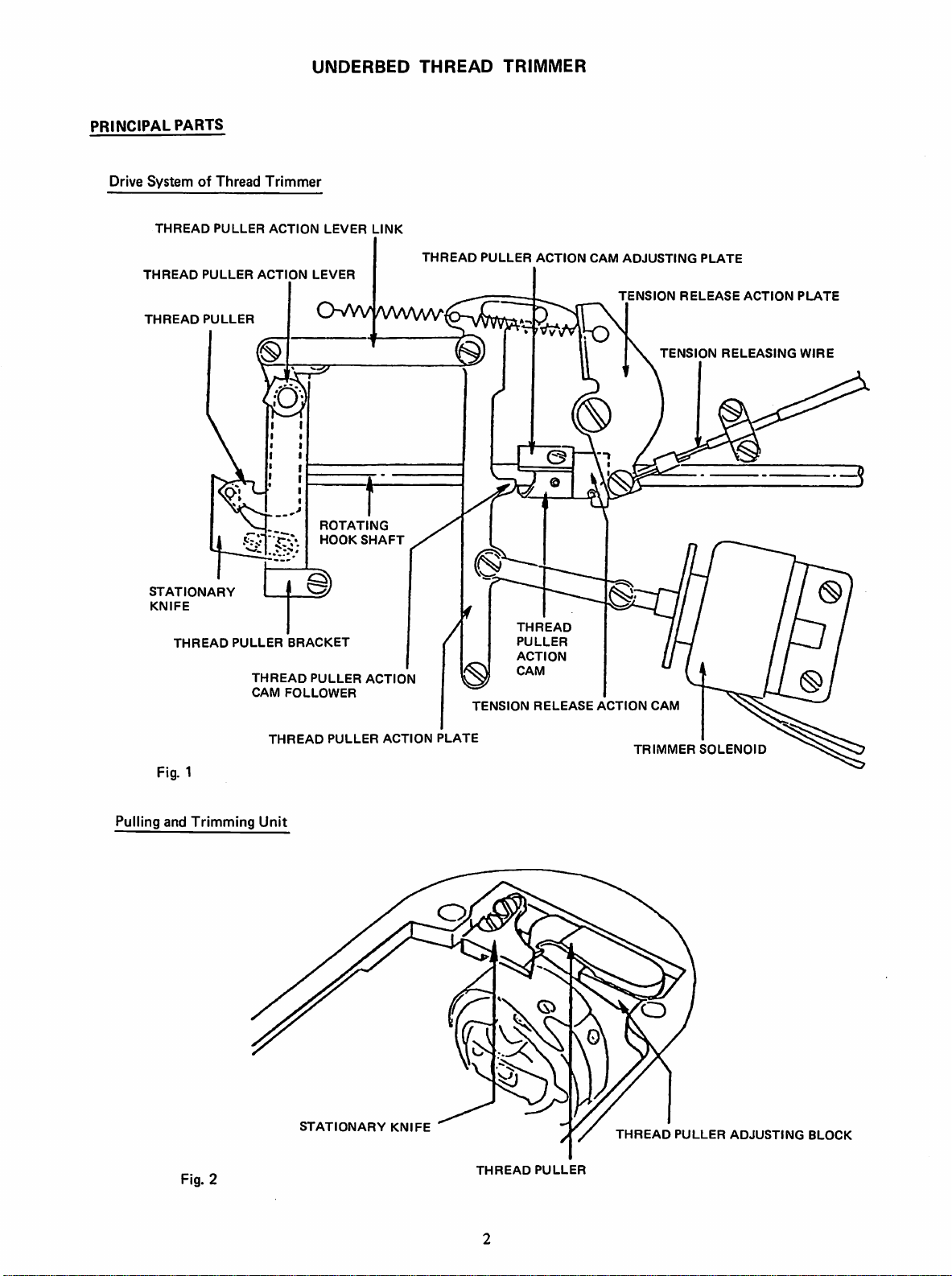
UNDERBED
THREAD
TRIMMER
PRINCIPAL
Drive
SystemofThread
THREAD
THREAD
STATIONARY
KNIFE
PARTS
THREAD
THREAD
PULLER
PULLER
PULLER
ACTION
PULLER
THREAD
CAM
Trimmer
ACTION
BRACKET
FOLLOWER
LEVER
LEVER
ROTATING
HOOK
PULLER
LINK
/WVW/
SHAFT
ACTION
THREAD
PULLER
TENSION
ACTION
THREAD
PULLER
ACTION
CAM
RELEASE
CAM
ACTION
ADJUSTING
TENSION
TENSION
CAM
PLATE
RELEASE
ACTION
RELEASING
PLATE
WIRE
Fig. 1
Pulling and
Trimming
Fig. 2
THREAD
Unit
PULLER
STATIONARY
ACTION
KNIFE
PLATE
THREAD
PULLER
TRIMMER
THREAD
SOLENOID
PULLER
ADJUSTING
BLOCK
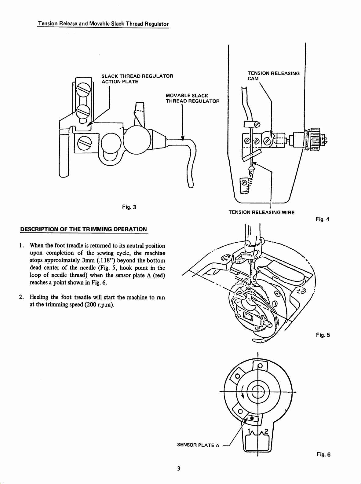
Tension Release and Movable Slack Thread Regulator
SLACK
THREAD
ACTION
PLATE
Fig. 3
DESCRIPTION
1.
When
upon completion
OF
THE
TRIMMING
OPERATION
the foot treadle is returned to its neutral position
of
the sewing cycle, the machine
stops approximately Smm (.118") beyond the bottom
dead center of the needle (Fig. 5, hook point in the
loop of needle thread) when the sensor plate A (red)
reaches a point shown in Fig. 6.
REGULATOR
MOVABLE
THREAD
SLACK
REGULATOR
TENSION
TENSION
CAM
RELEASING
RELEASING
WIRE
Fig. 4
2. Heeling the foot treadle will start the machine to run
at the trimming speed (200 r.p.m).
SENSOR
PLATE
Fig. 5
A
Fig. 6
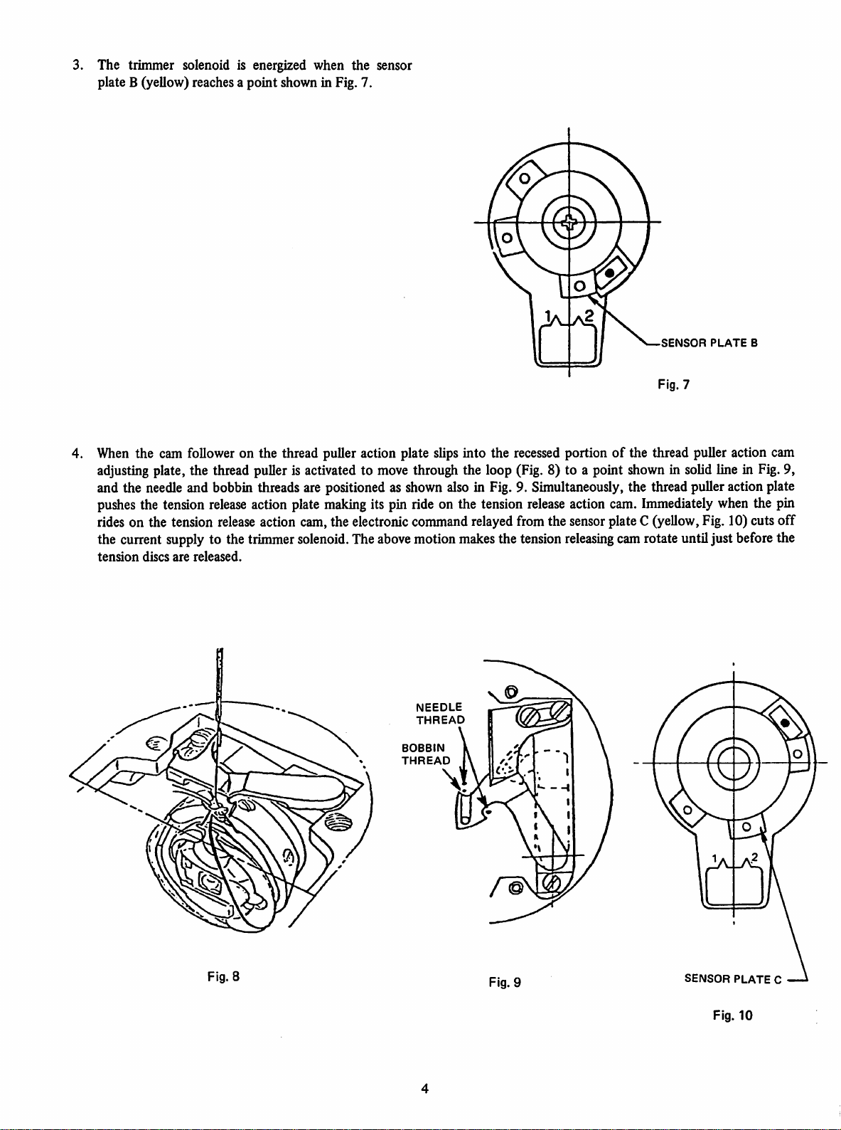
The trimmer solenoid is energized when the sensor
plate B (yellow) reaches a point shown in Fig, 7.
SENSOR
Fig. 7
PLATE
B
When the cam follower on the thread puller action plate slips into the recessed portionofthe thread puller action cam
adjustingplate, the thread puller is activated to move through the loop (Fig. 8) to a point shownin solid line in Fig.9,
and the needleand bobbin threads are positioned as shown also in Fig. 9. Simultaneously, the thread pulleraction plate
pushes
rides on the tension
the current supply to the trimmersolenoid. The
tension
the tension
discs
are
released.
release
release
action plate
making
its pin ride on the tension
release
action cam.Immediately when the pin
action cam,the electroniccommandrelayedfrom the sensorplate C (yellow,Fig. 10) cuts
above
motion
THREAD
BOBBIN
THREAD
NEEDLE
makes
the tension
releasing
camrotate untiljust beforethe
off
©
Fig. 8
Fig. 9
n
SENSOR
Fig.
PLATE
10
C
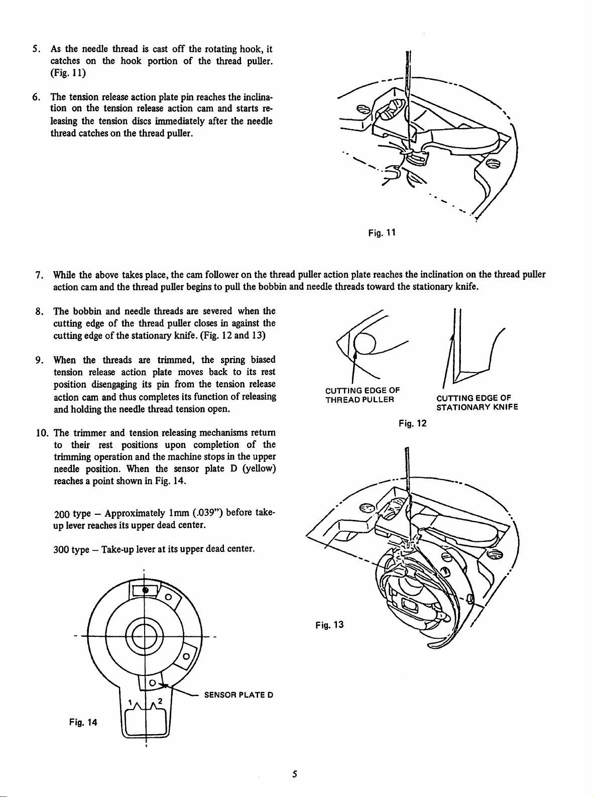
5. As the needle thread is cast
catches on the hook portion
off
the rotating hook, it
of
the thread puller.
(Fig. 11)
6. The tension release action plate pin reaches the inclina
tion
on
the
tension
release
action
cam
and
starts
re
leasing the tension discs immediately after the needle
the
thread catches on
thread puller.
Fig. 11
7.
While
the above takesplace,the cam followeron the thread puller action plate reachesthe inclinationon the thread puller
action camand the thread puller beginsto pull the bobbin and needle threads toward the stationary knife.
8.
The
bobbin
and
needle
threads
are
severed
when
the
cutting edgeofthe thread puller closes in against the
cutting edgeofthe stationary knife. (Fig. 12 and 13)
9. When the threads are trimmed, the spring biased
tension release action plate moves back to its rest
position
action cam and thus completesits function of
disengaging
its pin from the tension release
releasing
and holding the needle thread tension open.
10. The trimmer and tension releasing mechanisms return
to their rest positions upon completion
of
the
trimming operation and the machine stops in the upper
needle position. When the sensor plate D (yellow)
reaches a point shown in Fig. 14.
200 type -
Approximately
1mm
(.039") before
take-
up leverreachesits upper dead center.
300 type —
Take-up
leverat its upperdeadcenter.
CUTTING
THREAD
EDGE
PULLER
OF
Fig. 12
CUTTING
STATIONARY
EDGE
OF
KNIFE
SENSOR
Fig. 14
PLATE
D

11. Upon completion of the trimming operation, the
thread wiper makes a
the needle thread in proper position for starting the
next
sewing operation.
swivelling
movement to place
TIMING
When
Be
ServiceManualForm U3208 for regular 591 machine).
Check
AdjustmentofNeedle
When
from
Needle Stop Positions
AND
SETTING
checking the operationofthe trimmer mechanism by manualactuation of the mechanisms.
a. Be sure to
b. Push thread puller action plate toward camwhen take-upleverisalmost at its lower dead center.
NOTE:
suretocheck
and
checking
the
control
The
pushed
of
the
adjust
tum
machine pulley over toward frontofmachine.
thread
puller
may
strike
the
needle
towardthe cam as
needle
bar.
that the
the
and
box.
machineiscorrectly
trimmer
Stop
Position
making
adjustmentsofneedle
mechanism
described
in the
above
adjusted
order
stop
and
damage
since
instructedinthis
itself
and
the
the rotating hook shaft
before
making
adjustments
manual
positions,besuretodisconnect
needle
since
unless
makes
to the
it is
interlocked
the
the
two revolutions
thread
trimmer
trimmer
puller
action
against
mechanism.
with
many
and
wiper
plate
onecycle
(Refer
to
other
area.
connectors
it
a.
Lower
Needle
Position
The
lower
needle
positionisapproximately
does
not
call
for
absolute
skip stitching.
b. Upper NeedlePosition
The
upper
needle
position
upper
dead
centerandthe upper
center.
Adjust
upper
needle
position.
accuracy
of the
positionas accurately as
and
200
needle
minor
type
position
3mm
(.118")
adjustments
beyond
the
maybemade
machineisapproximately
of the 300 type
possiblebyrunning
machineiswhen
andstopping
bottom
ifthe
1mm
dead
threads
(.039")
machine
center
ofthe
needle.
cannotbeproperly
before
the
take-up
the
take-up
several
lever
times
This
1st
position
trimmed
lever
is at itsupper
to checkfor correct
dueto
reaches
its
dead
Adjustments
AH
sensors
are
correctly
retimingorresetting
timed
becomes
andset
necessary,
before
adjust
leaving
the
bycorrectly
factory.
positioning
If,
however,
the
sensor
this
timingorsetting
plates.
has
been
disturbed
and
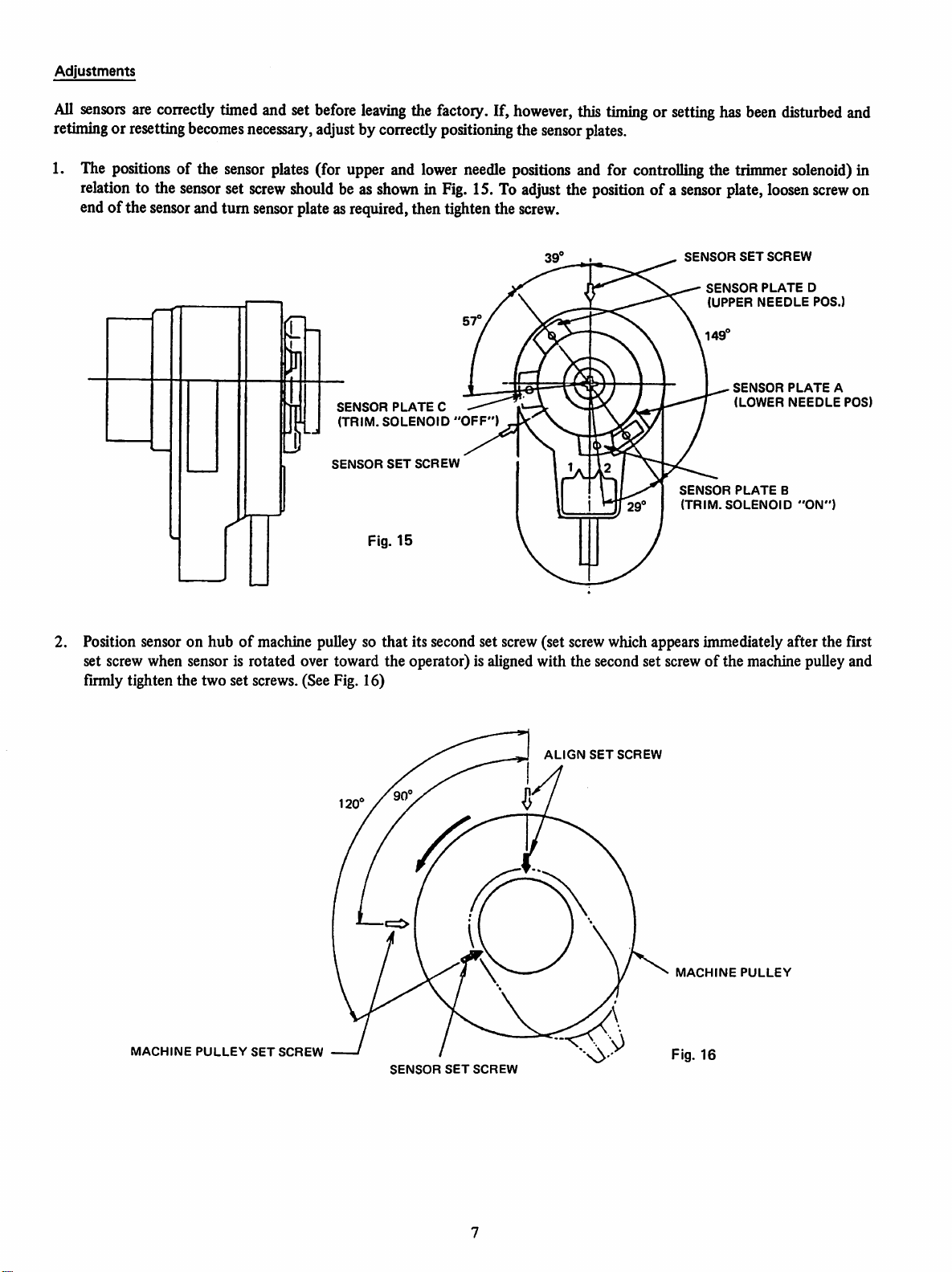
1. The positions of the
relation
to the
sensor
endof the sensorand turn
sensor
set
screw
plates
(for upper and
should
sensor
be as
showninFig.
plateasrequired,then tighten the
SENSOR
(TRIM.
SENSOR
PLATE
SOLENOID
SET
Fig.
15
lower
C —
SCREW
needle
15. To
"OFF")
positions and for controlling the
adjust
the
position
of a
sensor
screw.
39'
SENSOR
SENSOR
(UPPER
149'
SENSOR
(TRIM.SOLENOID
trimmer
plate,
SET
SENSOR
(LOWER
PLATE
solenoid)
loosen
SCREW
PLATE
NEEDLE
PLATE
NEEDLE
B
screw
D
POS.)
"ON")
in
on
A
POS)
Position sensor on hubofmachine pulley so that its second set screw (set screw which appears immediately after the first
set screw when sensor is rotated over toward the operator) is alignedwith the second set screwofthe machine pulley and
firmly tighten the two set screws. (See Fig. 16)
ALIGN
SET
SCREW
MACHINE
PULLEY
SET
SCREW
SENSOR
SET
MACHINE
Fig.
SCREW
PULLEY
16
 Loading...