

Singer 451K51 Service Manual
Form
(1266)
K6518
HIGH
LOCK
SERVICE
PARTS
SINGER
451k51
SPEED
STITCH
MANUAL
LIST
SINGLE
VERTICAL
TRIMMER
NEEDLE
MACHINE
Machine
451K51
•A
TrademorkofTHE
SINGER
THE
COMPANY
SINGER
Copyright Under International Copyright Union
COMPANY
PrintedInGreot
Britain

CONTENTS
Page
DESCRIPTION 3
SETTING
LUBRICATION 5. 6
INFORMATION
Alignment
Arm
Arm
Arm
Arm
Automatic
Ball Bearings and Needle Bearings 15, 25, 26
Bobbin
Bobbin
Bobbin
Bobbin
Bobbin
Bobbin
Bobbin
Bobbin
Broken
Carefree Operation Hints 14
Centralisation
Change of Stitch Length
Check-Spring
Cleaning
Connection
Common
Cover
UP
FOR
Shaft
with
Shaft
Shaft
Connection
Shaft
Connection
Lubrication
Case
Case
Holder
Case
Holder
Case
Slide
Thread
Thread
Winder
Thread
Tension
of
Belt,
CausesofStitching
Guard
(Take-up)
OPERATOR
Hook
Needle
Feed
Arm
Driving
Belt
Belt
Dog
Shaft
Pulley
Guard
Troubles
Shaft
7-14
Page
15i
25,
3,
25,
8-10,14
16,
18,
16,
7,
5» 8
7,
11,22
18, 19
5, 12, 20, 24
3, 25
12, 16
Daily Care 5
Damaged
Damaged
Dimensions
Drawing
Drip
Face
Feed
Feed
Feed
Feed
Feed
Feed
Feed
Feed
Formation
Fraying
Gib
Hints
Hook
Clearance
Description
Lubrication
Removal
Stringing
Timing
Hook
Hook
Hook
Hook
Knee
Knee
Knives
Aligning
Eliminating
Replacing
Setting,
Length
Light
Needles 7
Parts
of
Machine
Up Bobbin
Pan,
Plate,
Dog
Driving
Driving
Driving
Driving
Mechanism
Movement,
Reversing
of
(Feed
Driving
for
Carefree
Driving
Oil
Shield,
Oil
Wick
Section
Lifter
Lifter
Holder
Lower
Correct
of
Stitch
Fixture
Installation
Removal
of
Material
to
and
•
Rod
Upper
Bracket
Knives
Height
Thread
Eccentric
and
Reversing
Eccentric
Eccentric
(Pendant
Description
Lever
Stitch
Eccentric)
Operation
Needle
Replacement
Shaft
Installation
Spring
KnifetoLower
Side
Movement
and
Mounting
and
Gib
Adjusting
Stop
Upper
Seat
Replacement
Mechanism
Disc
Link)
Pin
Knife
of
Knife
Knives
(Upper)
to
15, 21, 22
3,
16,
3,
21,
15,
3,4,14
11,
4
INDEX
15
26
25
26
6
7
23
18
9
10
12
21
7
14
3
9
4
19
22
22
22
22
22
21
22
10
7
22
14
17
3
6
23
18
17
25
6
6
23
22
13
13
14
13
22
3
Page
TIMING
REMOVAL
PARTS
PARTS
Locking
Loop
Machine
Machine
Machine
Needle
Needle
Needle
Needle
Needle
Needle
Needle
Needle
Needle
Needle
Needle
Oil
Oil
Oil
Pendant
Perfect
Position
Preliminary
Preparation
Presser
Presser
Pressure
Prevention
AND
PRINCIPAL
CHART
LIST
Feed
Lift
Pulley
Rest
Storage
Bar
Bar
Bar
Alignment
Bearings
Beakage,
to
Hook
Guard
Threading
Thread
Thread
Reservoir
Shield
Wick(Hook)
Link
Stitch
Finger
Bar
Foot
of
Stitch
Length
ADJUSTING
AND
ASSEMBLIES
Driving
Pin
and
Connection
to
Presser
Tension
Tension
(Hook)
Feed
Inspection
for
Sewing
and
Presser
of
Unauthorised
REPLACEMENT
Eccentric
Bushing
Link
Foot,
Prevention
Clearance
Releaser
Mechanism
Bushing
Foot
Clearance
Change
OF
of
and
11, 14,
15-22
23-26
28,
30,31
3,5,14,
15-17,
7,
14,
16,
10, 18,
10,
3,5,25
15,
19,
11,22
Page
4,
3,
6, 17
Puckering
(Arm
Shaft
Pulley
Pulley,
Removing
Rest
Pin
Reverse
Reversing
Rock
Shafts
Rotary
Sewing
Machine
Broken
Feed
Lever Stop Pin 22
Take-up
Hook
Connection Belt) 25, 26
Thread
(See
(See
"Take-up")
"Hook")
- 3, 5, 14, 25
3,
4,
11, 19,
Speed 3,
Setting
Specifications
SpillageofBobbin
Starting
Stitch
the
Needle 7
Thread
to Sew 12
Formation
Stitch Length 3, 11, 22
Stitch
Regulator
Stitching
Stringing
Troubles,
the
Needle
Causes 7
Guard
(Hook)
8, 11
Superfmish
Tacking
Take-up.... 3,
Take-up
Tension
Cover
Devices
Guard
3,
11,19
15,
12,.
Tension Releaser (Needle Thread) 20
Threading
Thread
Thread
Thread
Trimmer
Beakage
Cutters
Tensions
7, 12
3,
10,
Adjusting
Changing
Trimming
Margin
Disengaging
TurningaCorner
V-Belt
Wearing
Winding
Checks
the
Bobbin 8
6,
15,
20,
29
22
15
25
14
26
26
20
15
18
17
18
19
20
10
15
20
20
22
21
12
14
22
24
14
15
10
19
16
7, 9
12
19
12
12
12
12
21
18
14
5
7
7
6
6
3
9
8
3
3
DESCRIPTION
Machine
light
and
Lock
stitch
Single
Socket-type
Short
Drop
with
and
•
return
ing
thread
•
forward
arm,
feed.
reinforced
uniform
Reverse
to
and
strong
breakage.
Maximum
and7to
Vertical
the
right
Special
the
lineofstitching
on
order.
will be
The
will
9/64
fitted
upper
for
inch.
straight
451
medium
(Stitch
needle,
flat
stitch
feed,
forward
Trimmer.
of
seam
fittings
Unless
to
knife
K51,
weight
Catalogue
needle
bed
Pendant
feed
length
hand
stitch.
seam
stitch
the
as
for
trim
may
stitching.
for
stitching
fabrics.
Type
bar
link
bar
insures
operated,
Performs
reinforcing
length,
inch
Trims
desired.
trimming
can
be
otherwise
1/8
inch
be
thrown
#301)
1361
feeding
at
all
in
reverse.
1/8
furnished
ordered
to
Upper
and
(88x9)
level
speeds.
with
6
to
to
3/32
right
out
trimming
mechanism
feed
motion
with
spring
precise
minimum
the
5/16
inch
inch
if
specified
machine
of
seam.
of
action
knife
stroke
tack
inch
from
to
at
Tapped hole and seat in rear of
for
mounting
a
light
fixture.
arm
provided
Compact stitch length mechanism is easy to
read
and
to
set.
Enclosed
knee
Needle
Presser
(.281)
lifter
inch.
knee
228710.
bar
bar
lifter
rod
and
stroke, 1-9/64 (1.140) inches.
lift
(capacity
of
machine),
connection
Bed dirnensions: Length, 15-11/16 inches.
Width 7 inches. Working space
needle,8inches.
Double
arm
Needle
connections
Nylon
shaft
Controlled
hook
TOP
FROM
shaft
bearings
insert
and
shaft.
OF
THE
shielded ball
andatpulley
for
and
for
needle
bearings
feed
lifting
pressure
MACHINE
OPERATOR.
bearings
endofhook
feed
driving
bar
for
rock
shaft.
lubricated
PULLEY
feed
at
right of
at
both
driving
and
feed
connecting
driving
bearings
TURNS
ends
to
9/32
of
shaft.
lifting
link.
rock
on
OVER
Modified,
constant
ments.
Long
axis
(belt
regulated.
One
oil
holes
serve
Rotary
precise
stitching
threads
weight—permitting
"wash
Tension
rotary
other
hazards.
Two
vents
wrapping
take-up.
removes
Durable,
270926,
readily
moved.
Large
for
3/8
side
diameter
diameter
inches.
single
thread
Easy
to
point
rotary
driven);
reservoir
all
tension
thread
and
tension
with
and
guard,
control
all
materials
wear"
thread
The
excess
steel-reinforced,
from
arm
accessible
rim,
aluminium
inch
V-belt,isdesigned
of
for
5/16
control
thread.
automatic
and
principal
and
types
sewing.
mounted
from
cutters;
of
broken
other,
broken
shaft
when
belt
inch
rotary
to
Simple
sewing
three
bearings
pre-tension
throughout
of
of
lightest
broken
One,
on
rear
thread
to
rear
machine
groove,
round
take-up
meet
hook
lubrication
easily
natural
light
tensions
on
face
threads,
on
thread
rubber
hook
arm
2.9
leather
hook
to
on
in
devices
speed
and
and
plate,
face
around
of
thread
from
driving
pulley
for
safety.
inches.
maintains
require
adjust.
horizontal
can
accessible
machine.
achieve
range
synthetic
medium
for
perfect
protects
lint
plate,
rotary
guard,
take-up.
driving
shaft,
cover
276445,
Effective
belt,
and
pre
belt
is
Out
2-3/8
oil
re
be
of
CAUTION
Do
not
start
oughly
per
speed
period
mum
time
principal
ment
machine
closeiy
is
the
operator
use.
efficient
Disregard
siderable
oiled,
Maximum
minute,
•
Run
the
• A
machine
of
speed
for
and
•
Reduce
woven
Maximum
nature
and
Never
speed
a
first
time,
oil
bearing
at
force
of
damage
machine
as
speed
with
new
few
that
should
for
the
to
reach
adequate
top
speed.
speed
or
efficient
of
the
the
machine
for
this
instructed
recommended
these
machine
days.
points
treated
operation,
type
the
precaution
to
until
SPEED
exceptions
has
been
be
run
first
few
the
moving
for
lubrication
of
machine
material.
speed
of
thread
beyond
work
machine.
on
at
slower
freedom
is
the
being
could
it
has
is
more
idle,
been
4, 5
5000
. . .
for
than
pages
a
minutes
parts.
before
when
dependent
ability
and
material
its
maximum
accomplished.
result
and
stitches
moderate
a
maxi
to
Check
of
move
running
sewing
of
in
thor
long
allow
upon
the
con
6.
,
in
SETTING
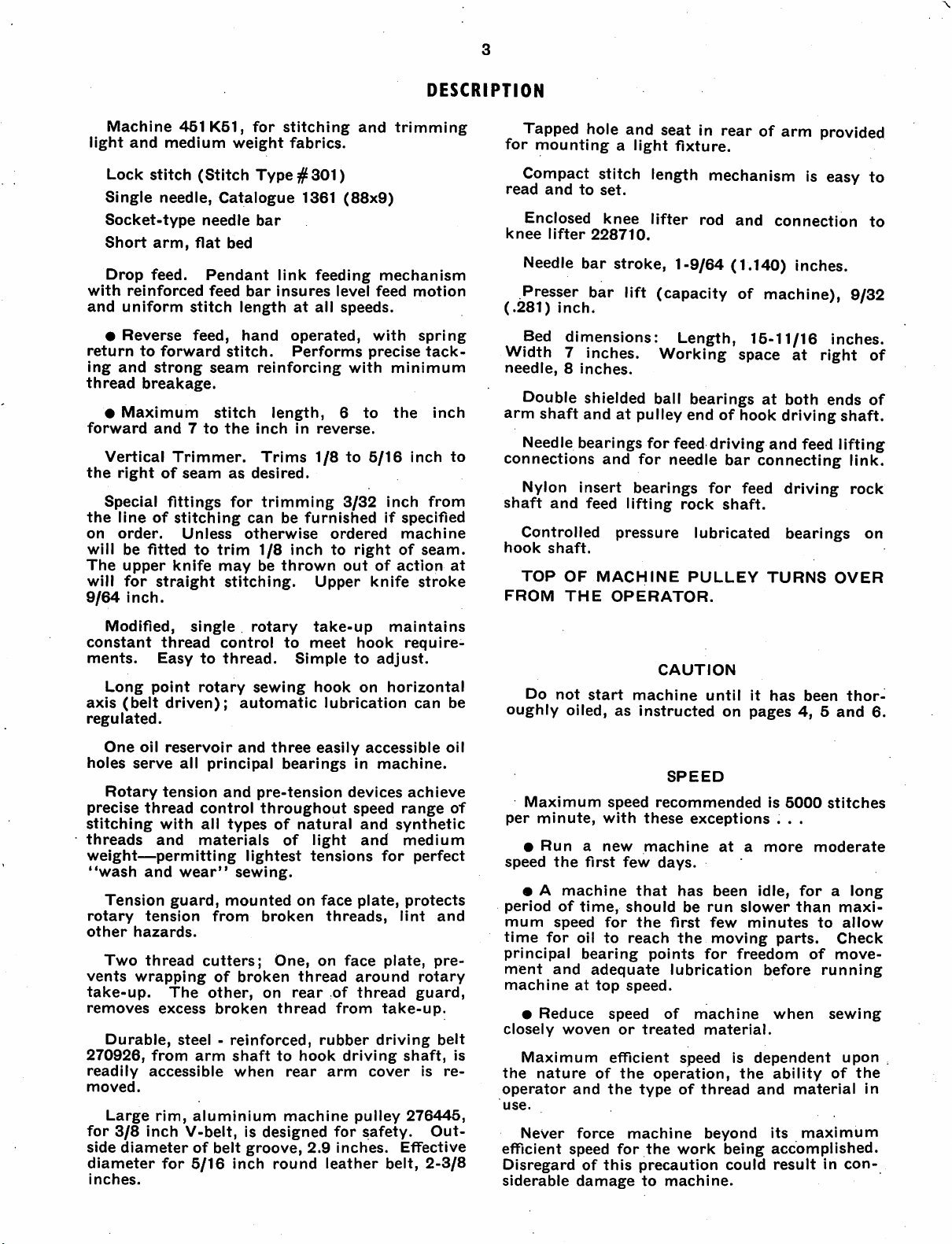
DRIP
PAN
Position
in Fig. 2,
edge
Using
enough
rock
KNEE
Using
Fig. 2)
table.
and
out
striking
Locate
equidistant
pan.
willbedirectly
in
machine;
Raise rock
below
certoin platform is
curely
Knee
suit
clamping
drip
pan
with
its
of
lever
LIFTER
Locate
fall
machine
four
in
rod
three
fasten
through
rock
cut-outintable.
3/4
inch
table
cut-out
(shown
7/8
rock
bracket
hole
edgeofhole.
lever
from front
Make
certain
under
then
securely
lever
knee
lifting
tighten
the
clamping
plate7may
requirementsofthe
screw
8. Knee
on
undersideoftable,asshown
right
end
wire
nails,
to
avoid
in Fig. 2).
inch
wood
lever
bracket
2sothat
provided
extension
and
rear
that
platform
knee
lifting
tighten
rod
5 to
rodinmachine,
turnedasshown
screw
be raised, lowered or
operator,
plate
moved toward the left or right
rear,
as
required
Tighten both screws 8
position is
Set
stop
stud
as
soonasknee
to
trip
hand
ing
screw
12.
MACHINE
HEAD
Machine
four
corners
tened.
Machine
head
except
chine
rest
pin
after
obtained.
11 to
lifter
lifter on
head
should
of
cut-out
hinges
when
on
table.
loosening
and
10 securely
stop
the
raises
presser
machine.
rest
upon
in
table.
must
notberequiredtosupport
machine is tilted back
UP
even
with
right
fasten
screws
rock
for
3tohold
edges
drip
interference
(shown
2 to
underside
lever
rod
it in
drip
rock
of hole in drip
at
top
end
pan
can
pan
lever
rodA,^g. 5, page 5,
clamp
bring
whenatrest.
6.
arm9may
and
clamping
actionofthe
Securely
Machine
screw
Its
platform
in Fig. 2
turned
after
loosening
also
toward front or
screw
when
knee
foot
high
tighten
cushioning
is
not
upon
inside
low
with
at
rise
with
rod
of rod
4.
just
Make
and
se
10.
correct
lifter
enough
clamp
pads
fas
ma
of
be
FRONT
EDGEOFTABLE
1,
PLATFORM
ROCK LEVER
ROD—
I ^
'f I
i# ;
to
Fig. 2.
Drip
Pan
and
beneath
in
the
Kne« Lifter
Table
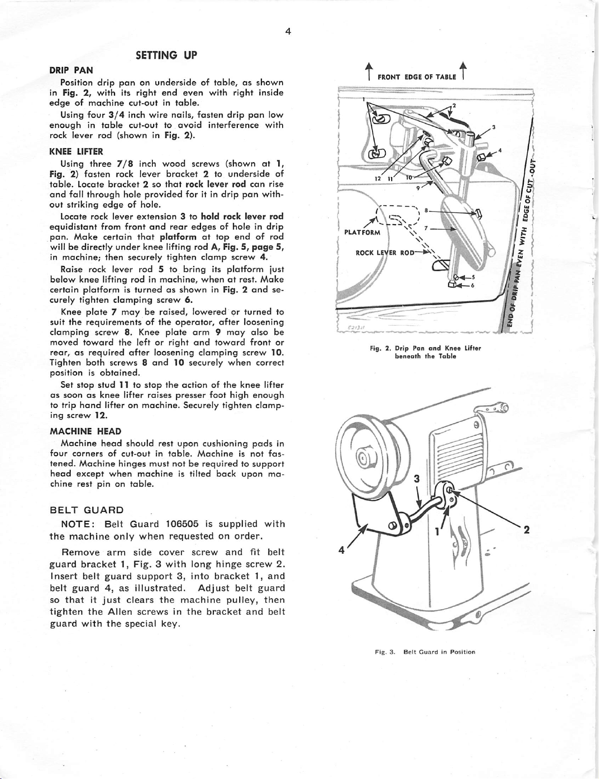
BELT
the
guard
Insert
belt
so
tighten
guard
NOTE:
machine
Remove
bracket
belt
guard
that
with
GUARD
It
just
the
Belt
only
arm
guard
4,
as
Allen
the
Guard
when
side
1,
Fig.3with
support
illustrated.
clears
screws
special
106505
requested
cover
3,
the
in
key.
screw
long
Into
Adjust
machine
the
is
supplied
on
hinge
bracket
bracket
order.
and
belt
pulley,
fit
screw
1,
guard
and
with
belt
2.
and
then
belt
Fig.3.Belt
•>;
GuardInPosition
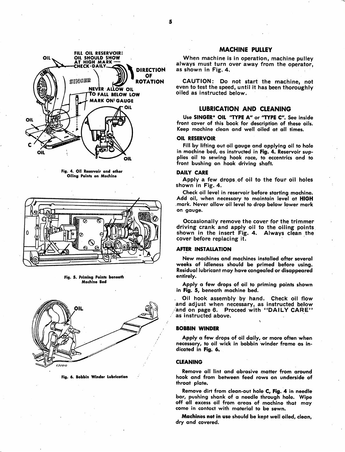
OIL
FILL
OIL
SHOULD
HIGH
reservoir:
OIL
AT
NEVER
O FALL BELOW
MARK
Fig. 4. Oil Reservoir
Oiling
PointsonMachine
MARK
and
SHOW
—
AlToW
ON*
GAUGE
other
oil
LOW
OIL
OIL
DIRECTION
OF
ROTATION
When
always
as
must
shown
CAUTION:
eventotest
oiled
as
instructed
LUBRICATION
Use
SINGER*
machine
turn
in
Fig.
the
OIL
MACHINE
Is In
over
4.
Do
not
speed,
below.
'TYPE
PULLEY
operation,
away
start
from
the
untilithas
AND
CLEANING
A"or"TYPE
machine
the
machine,
been
thoroughly
C".
pulley
operator,
not
See
inside
front cover of this book for description of these oils.
Keep
machine
OIL
RESERVOIR
Fill
by lifting out oil
in machine bed,asinstructed in Fig. 4. Reservoir
plies oil to
clean
sewing
end
well
oiledatoil times.
gouge
and
applying oil to hole
hook race, to eccentrics
sup
and
front bushing on hook driving shaft.
DAILY
shown
Add oil, when necessary to maintain level
mark. Never allow oil level to
on
CARE
Applyafew
In
Fig.
drops.of
4.
Check oil level in reservoir
gauge.
oil
to
before
drop
the
four
oil
starting machine.
at
below lower
holes
HIGH
mark
to
Fig. 5. Priming Points
Machine
Fig. 6. Bobbin Winder Lubrication
beneath
Bed
Occasionally
driving
shown
cover
AFTER
before
INSTALLATION
New
crank
in
machines
and
the
replacing
remove
insert
and
the
apply
Fig.
it.
machines
cover
oil to
4.
installed
for
the
Always
the
oiling
clean
after
trimmer
points
the
several
weeks of idleness should be primed before using.
Residual lubricant
congealed or
disappeared
may
have
entirely.
Apply a few
in Fig.5,beneath
Oil
hook
and
adjust
and
on
page
as
instructed
BOBBIN
WINDER
Apply a
necessary,
dicated
CLEANING
hook
throat
in Fig. 6.
Remove
and
plate.
Remove
drops
of oil to priming points shown
machine
assembly
when
few
necessary,
6.
Proceed
above.
drops of oil daily,ormore often
to oil wick in
all
lint
and
from
between
dirt
from
clean-out
bed.
by
hand.
with
bobbin
abrasive
feed
as
instructed
"DAILY
winder
matter
rows
hole C, Fig. 4 in
Check
frameasin
from
on
underside
oil
flow
below
CARE"
when
around
needle
of
bar, pushing shank of a needle through hole. Wipe
off all excess oil from
come
in
contact
with
areas
material
of machine that may
to
be
sewn.
Machines not in use should be kept well oiled, clean,
dry
and
covered.
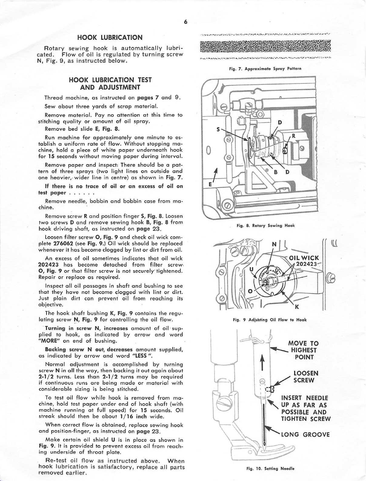
HOOK
LUBRICATION
Rotary
cated.
N.
Fig.9,as
Thread machine,asinstructed on
Sew
Remove
stitching
Remove
Run
tablish
chine, hold a piece of white
for 15
Remove
tern of
one
heavier,-wider
If
test
paper
Remove
chine.
Remove screw R
two
hook
Loosen
plete
whenever
An
202423
O, Fig. 9orthat
sewing
Flowofoil is
HOOK
hook
instructed
LUBRICATION
AND
Is
automatically
regulated
below.
ADJUSTMENT
by
TEST
turning
pages7and
about
three
material.
quality
bed
machine
a uniform
seconds
without
paper
three
sprays
there
is
no
needle,
screwsDand
driving
276062
shaft,asinstructed
filter
screwO,Fig. 9
(see Fig. 9.) Oil wick
yardsofscrap
Pay
no
or
amount
slide
E, Fig. 8.
for
approximately
rateofflow.
moving
and
inspect:
(two light lines on outside
lineincentre)asshown
trace
of
oil
bobbin
and
remove
and
position
sewing
material.
attentionatthis
of oil
spray.
one
minute
Without
paper
paper
There
or
on
bobbin
finger
on
and
stopping
underneath
during
should
excess
case
S, Fig. 8. Loosen
hook
B, Fig. 8
page
check
shouldbereplaced
it has become clogged by lint or dirt from oil.
excess
has
of
become
oil
filter
sometimes
indicates
detached
screwisnot
from
securely
be o
in Fig.
of
from
23.
oil
wick
that
filter
tightened.
lubri
screw
9.
time
to es
ma
hook
interval.
pot-
and
oil
on
ma
from
com
oil
wick
screw
Fig. 7.
Approximate
to
7.
Fig. 8. Rotary
Repairorreplaceasrequired.
Inspect all oil
that
they
Just
plain
passagesinshaft
have
not
dirt
can
become
prevent
clogged
oil
and
bushingtosee
with
lintordirt.
from
reaching
its
objective.
The
hook
shaft
bushing
lating
screw
N, Fig. 9
Turninginscrew
plied to hook,
"MORE" on
end
as
of
Backing screw N out,
as
indicated
Normal
screw
N in ail
2-1/2
if
continuous
considerable
To
test
chine, hold test
machine
streak
by
adjustment
the
turns. Less
runs
sizingisbeing
oil
flow
running
should
then
arrow
way,
than
are
while
paper
at
When correct flow is
and
position-finger, as instructed on
Make
certain oil shield U is In placeasshown in
Fig. 9. It is
ing
underside
Re-test
hook
removed
providedtoprevent
of
throat
oil
flow
lubricationissatisfactory,
earlier.
K, Fig. 9
for
controlling
N,
increases
indicated by
bushing.
decreases
and
word
is
accomplished
then
backingitout
be
2-1/2
under
full
about
being
hook
speed)
turns
made
stitched.
end
1/16
obtained,
plate.
as
instructed
contains
the
amount
arrow
amount
"LESS
may
or
is
removed
of hook
for
15 seconds. Oil
inch
replace
poge
excess oil
above.
replace
the
regu
oil
flow.
of oil
and
word
supplied,
".
by
turning
again
about
be
required
material
from
shaft
(with
wide.
sewing hook
23.
from
reach
When
all
sup
with
ma
parts
Fig. 9
Adji/sting
L
o\ycy-
Fig. 10.
Sewing
Oil
I;
%
I
Setting
Sproy
Pattern
Hook
OILWICK
FlowtoHook
MOVE
.
"
INSERT
UP
POSSIBLE
TIGHTEN
^LONG
Needle
202423
HIGHEST
POINT
LOOSEN
SCREW
NEEDLE
AS
FAR
GROOVE
TO
AS
AND
SCREW
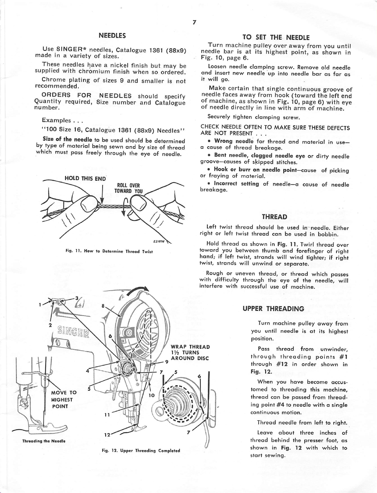
Use SINGER* needles, Catalogue
made
in a
variety
of
sizes.
1361
(88x9)
These needles have a nickel finish but may be
supplied
Chrome
recommended.
with
plating
chromium
of
finish
sizes9and
when
smaller
so
ordered.
ORDERS FOR NEEDLES should specify
Quantity required,
number.
Examples
"100
Sizeof the needle to be used
by
typeofmaterial
which
. . .
Size 16, Catalogue
must
pass
HOLD THIS END
Fig,
t1.
Size
number and Catalogue
1361
(88x9) Needles"
being
should
sewn
andbysizeofthread
freely
How to Detormine Thread Twist
through
ROLL
TOWARD
be determined
the
eyeofneedle.
OVER
YOU
TO
SET THE NEEDLE
Turn machine pulley over away from you until
needle
Fig.
and insert new needle up into needle
is
not
it will
needle faces
barisat
10,
page
Loosen
needle
go.
Make certain
away
its
6.
clamping
that
highest
point,
screw. Remove old
as
bar
single continuous groove
from hook
(toward
the
shown
needle
as far as
left end
in
of
of machine, as shown in Fig. 10, page 6) with eye
of
needle
Securely tighten clamping screw.
CHECK
ARE
•
a
causeofthreod
•
groove—causesofskipped
•
or
frayingofmaterial.
• Incorrect
breakage.
Left
rightorleft
Hold
toward you between thumb and forefinger of right
hand; if left
twist, strands will unwind or separate.
Rough
with difficulty through the eye of the needle, will
interfere
directlyinline
NEEDLE
NOT
Wrong
Bent
Hook
twist
threadasshown in Fig. 11. Twirl
OFTENTOMAKE
PRESENT . . .
needle
for
breakage.
needle, clogged needle eye or dirty needle
or burr on
setting
thread
twist
twist,
should
thread
strands
with
thread
needle
of needle—a
THREAD
and
stitches.
point—causeofpicking
be
usedinneedle.
can
be
will
wind tighter; if right
armofmachine.
SURE
THESE
material
cause
usedinbobbin.
thread
or uneven thread, or thread which passes
with
successful
use
of
machine.
DEFECTS
in use—
of
needle
Either
over
UPPER
Turn machine pulley
you until
position.
WRAP
Threading
the
MOVE
HIGHEST
POINT
Needle
TO
m
to/\\
to
Fig. 12. Upper Threading Completed
l'/2
AROUND
7 5
(Yi
THREAD
TURNS
DISC
Pass
through
through
Fig.
When
tomed
thread
ing
continuous
Thread
Leave
thread
shown
start
THREADING
needleisat
thread
threading
#12
12.
you
to
threading
canbepassed
point#4to
motion.
needle
about
behind
in
Fig.
sewing.
in
have
needle
from
the
12
from
points
order
become
this
from
withasingle
left to
three
presser
with
away
from
its highest
unwinder,
#1
shown
accus
machine,
thread
right.
inches
foot,
which
in
of
as
to
Turn
needle
Fig.
moves
12,
TO
machine
uptoIts
Page
7.
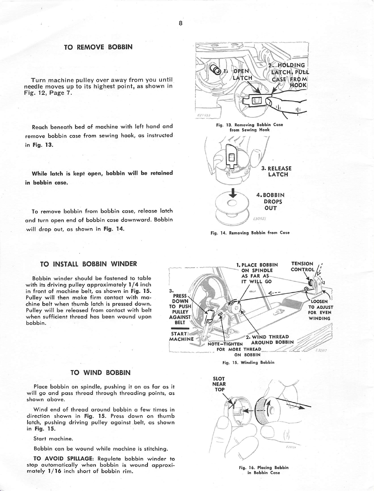
REMOVE
pulley
highest
over
BOBBIN
away
from
point,asshown
you
until
V-j1l\
rr6
m)
in
Reach
remove
in Fig.
beneath
bobbin
13.
bedofmachine
case
from sewing hook,asinstructed
with
left
hand
and
While latch is kept open, bobbin will be retained
in
bobbin
To
remove
case.
bobbin
from
bobbin
case,
release
latch
and turn open end of bobbin case downward. Bobbin
will
drop
out,asshown
TO
INSTALL
Bobbin
winder
should
with its driving pulley
in
frontofmachine
Pulley will then
chine
belt
when
make
thumb
Pulley will be releosed from contact with belt
when
sufficient
bobbin.
thread
in Fig.
BOBBIN
be
14.
WINDER
fastened
approximately
belt,asshown
in Fig.
firm contact with ma
latch is
has
been
pressed
wound
to
1/4
table
inch
15.
down.
upon
PRESS
DOWN
TO
pushPs
PULLEY
AGAINST
BELT
W/
i Ib
Fig. 13. Removing Bobbin Case
from
Sewing
Hook
ml
3.
RELEASE
LATCH
4.BOBBIN
DROPS
OUT
Fig. 14. Removing Bobbin from
1.
PLACE
BOBBIN
ON SPINDLE CONTROL
AS
FAR
WILL
AS—
GO
IT
Case
TENSION
\
Place
will go
shown
Wind
direction
latch,
in
Fig.
Start
Bobbin
TO
stop
automatically
mately
bobbin
and
pass
above.
end
of
shown
pushing
15.
machine.
canbewound
AVOID
1/16
SPILLAGE:
inch
TO
WIND
on
spindle,
thread
thread
through
around
in Fig. 15.
driving
pulley
while
Regulate
when
shortofbobbin
BOBBIN
pushing
it onasfarasit
threading
bobbin
Press
against
a
down
belt,
few
machineisstitching.
bobbiniswound
bobbin
rim.
points,
times
on
thumb
as
shown
winder
approxi
START^«s^
MACHINE
as
in
to
n
note::tTghten
FOR MORE THREAD _
^.=^2.
WIND
around
ON
BOBBIN
Fig. 15. Winding Bobbin
Fig. 16. Plocing Bobbin
in
Bobbin
THREAD
bobbin
Cot*
DRAW
DOWN
UNDER
HRFAirv.Al^
THREADTN
AND
SPRlN0^
I
U \\
[
/^SLOT
THREAD
INTO
3.TURN
OVER
THREAD
INTO
EYE
BOBBIN
AND
DRAW
UP
DELIVERY
, _
1(2
CASE
^
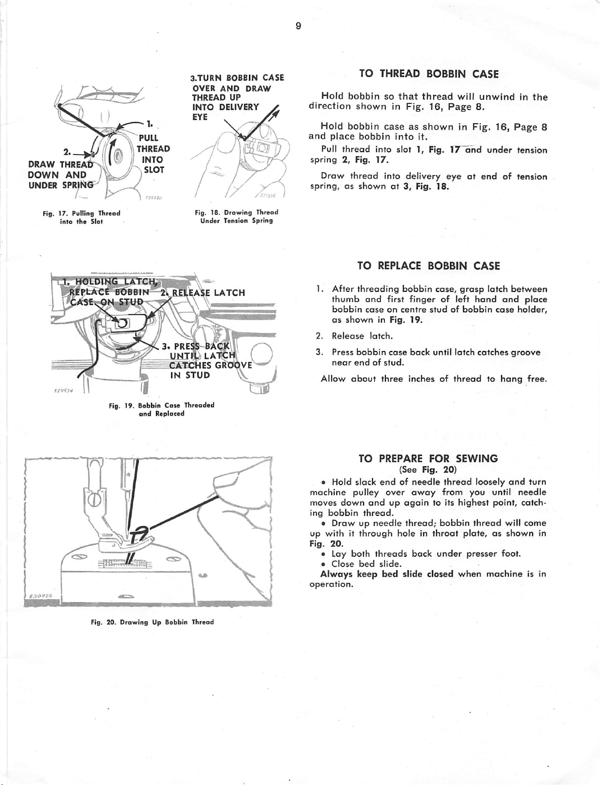
TO
THREAD
Hold
bobbin
direction
Hold
place
Pull
Draw
bobbin
thread
2,
thread
and
spring
spring,asshownat3,
so
that
shown
In Fig.
caseasshown
bobbin
Into
into slot 1, Fig. 17
Fig.
17.
into delivery
BOBBIN
thread
16,
it.
Fig.
will
Page
In
and
eyeatend
18.
CASE
unwind
8.
Fig.
under
16,
of
in
the
Page
tension
tension
8
Fig. 17. Pulling Thrsod
into
the
Slot
K'T^dlDING
gplPL-ACt^BO'BfflT
Fig. 19. Bobbin Cat* Threadod
LAt(
C3.
^CATCHES
and
Replaced
Fig. 18. Drawing Thread
Under
An
LATCH
PRE®
-BAOTV,
UNTlt;
LAtCW
GRO^VE^^
IN
STUD
Tension
^ i
Spring
{ )
TO
1. After
2.
3. Press
Allow
thumb
bobbin
as
shown
Release
near
threading
and
caseoncentre
latch.
bobbin
endofstud.
about
TO
• Hold slack
machine pulley
moves
ing
down
and
bobbin
•
Drawupneedle
thread.
REPLACE
first
in Fig.
case
three
PREPARE
endofneedle
over
up
bobbin
finger
19.
back
inches
(See Fig.
away
again
thread;
BOBBIN
case,
of
studofbobbin
until latch
of
FOR
20)
grasp
left
thread
SEWING
thread
CASE
hand
catches
loosely
from you until
to Its
highest
bobbin
thread
latch
case
to
point,
between
and
groove
hang
and
will
place
holder,
free.
turn
needle
catch
come
up with it through hole in throat plate, as shown in
Fig.
20.
o Lay
0
Alwoys
operation.
Close
both
bed
keep
threads
slide.
bed
back
slide
under
closed
presser
when
foot.
machine
is in
Fig. 20.
Drawing
Up Bobbin Thread
 Loading...