

Singer 371U User Manual
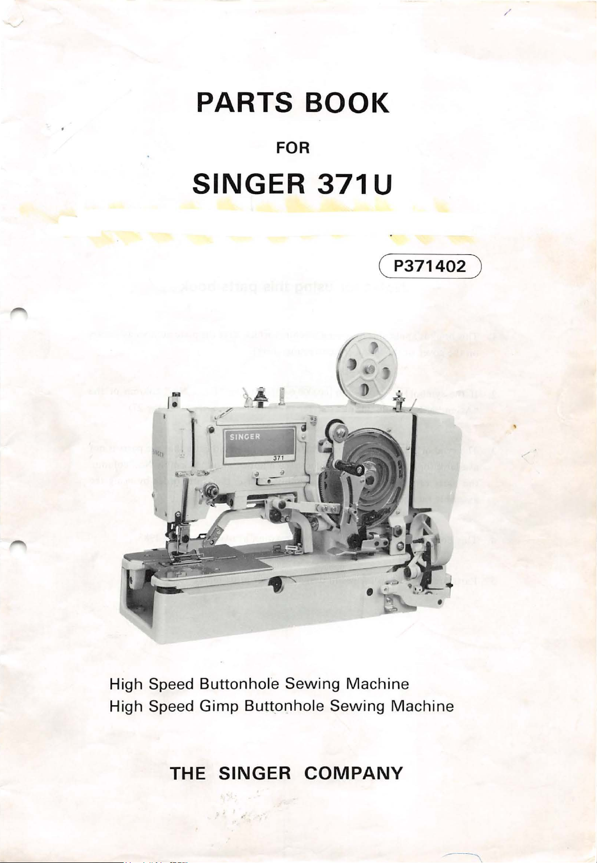
PARTS BOOK
FOR
/
SINGER
J
.
~~
( . b
371
U
(
P371402
l''
)
High Speed Buttonhol"e
High Speed
Gimp
THE
Buttonhole
SINGER
Sewing
COMPANY
Machine
Sewing
Machine
Notes for using this parts book
I.
This book
on the cover of this book (or correction sheet).
2.
If the
"Assembly No." column, please refer to the different parts list (page 27).
3.
The symbol
available for supply.
the parts can
assembly number.
4.
This book was prepared based on information available in May,
5.
Parts are subject to changes in design without prior notice.
is
applicable to sewing machines which have the plate number as shown
symbol!.__
___
I~
be
ordered as an assembly. Please, therefore, order by using the
__,I
or I000000-0-00I
is
in the "Parts No." column or the
I in the "Parts No." column indicates that the parts
If,
however, there
is
a number in the "Assembly No."column,
1983.
is
not
CONTENTS
A.
Machine body
A.
Machine body (2) ............................................................................... 2
B.
Needle
bar
C. Upper shaft mechanism .... ......... ............................. ............................ 4
D. Zigzag mechanism (I ) . . . . . . . . . . . . . . . . . . . . . . . . . . . . . . . . . . . . . . . . . . . . . . . . . . . . . . . . . .. . . . . . . . . . . . . . . 5
D. Zigzag mechanism (2) ...... .. ........ .... .. ......... ... ........ ... ....... ..... ... .. ........... 6
E.
Clutch mechanism ..................... ................... ...... ................................ 7
F.
Power transmitter mechanism .. . ..... .............. .......
G
0 Belt shift mechanism ........ ......... .............. ............ .................... ........... 8
H
0 Emergency stop mechanism ............................................................... 9
J 0 Tension pully mechanism ................................................................... 9
Ko
Presser foot mechanism . ... . . . .. ....... .. . . . ...... .................. ...... ......... ...... .. .. I 0
(I)
.............................................................................. .
and
thread take-up mechanism ........................................ 3
..
............................. 8
Lo
Feed mechanism (I) . . . . . . . . . . . . . . . . . . . . . . . . . . . . . . . . . . . . . . . . . . . . . . . . . . . . . . . . . . . . . . . . . . . . . . . . . . . I 0
Lo
Feed mechanism
Lo
Feed mechanism
(2)
...... ......
(3)
...........................................................................
..
. . ... . . ... . . .
..
. ..... ...... .... ... . . . . ....... .. . ....... ... . . .
II
12
M. Feed cam mechanism . . . . . . . . . . . . . . . . . . . . . . . . . . . . . . . . . . . . . . . . . . . . . . . . . . . . . . . . . .. . . . . . . . . .. . . . . I 3
N. Thread breakage detector .......... ...... ......... ...... ..... ... . . ...... ........ .. .... .. ....
P. Cutter mechanism . ... . . . . ... . . . ... ... . . ... . . .... ..... ....... .... ... . . . ... . . . .......... ...... ...
Q. Gimp Guide mechanism ................................................................
Ro
Tape winder mechanism .....................................................................
S. Vertical shaft
and
Lower shaft mechanism ................ ........................
T. Lubrication (I) ...................................................................................
T. Lubrication (2) ...................................................................................
U.
Threading mechanism
U.
Threading mechanism (2) ....................
V.
Bobbin winder ..... ............ ......... .. ... .. .... ..... .... .. ........ .. ..... .. ........ ...........
(I)
.... ..... ..... ..... ... . ..... ....... ... . ....... ................ .....
0.........................
.....................
13
14
~....
15
16
17
18
19
20
21
21
W 0 Upper Thread Trimmer mechanism
(I)
..............................................
W. Upper Thread Trimmer mechanism (2) ............ ~ ..............•..................
X. Lower Thread Trimmer mechanism ................................................... 24
Z. Accessories mechanism
(I)
.. . . . . ... . . . ... . .
..
. . ...... ... . . . . . . . ....... ... . . ... . . . ...... ....
Z. Accessories mechanism (2) ..................................... ............................ 26
DIFFERENT
GAUGE
MOTOR
INDEX
......................................................................................................
PARTS
PARTS
PULLEY
LIST .....................................................................
LIST .............................................................................
AND
BELTS .............................................................
22
23
25
27
35
37
38
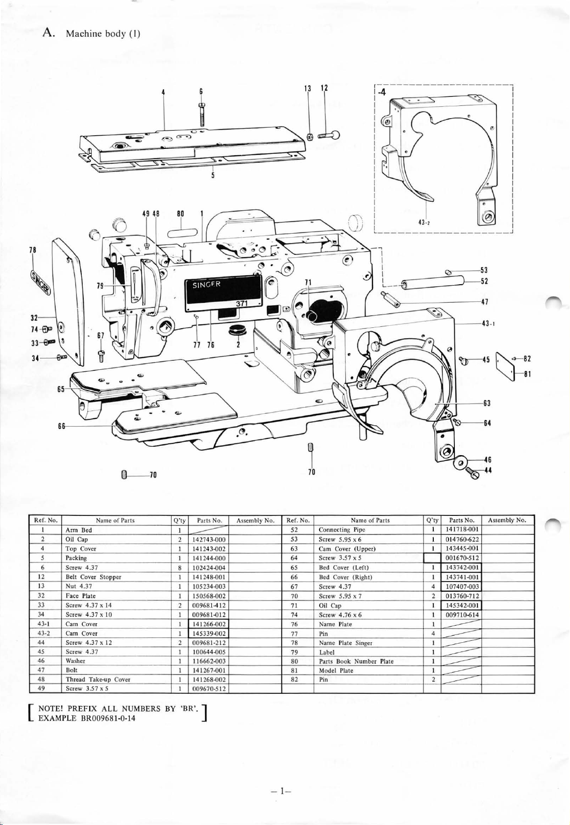
A. Machine body (I)
tl
--
70
Ref. No.
I
Arm Bed
2 Oil Cap
4
Top
5
Pa
Screw
6
12
B
13 Nut
32 Fa
33 Scr
34
Screw
43- 1 Cam Cover
43-2
Ca
44
Scr
45 Screw 4.37 I 100644.()05
46
Washer I 116662.()03
47
Dolt
48
Thread Take·up Cover
49
Screw 3.57 x 5 I
NOTE! PREFIX
[
EXAMPLE
Name
of
Parts
Cover I 141243.()02
cking
4.3
7
elt
Cover Stopper I 141248.()01
4.3
7
ce
Plate
ew
4.37 x 14
4.37
x 10
m Cover I 145339.()02
ew
4.37 x 12 2 00968 1-212
ALL
BR009681-0-14
NUMBE
RS
Q'ty
I
2 142743.()00
141244.()00
I
102424.()04
8
105234.()03
I
I 150568-
2 00968 1
009681.012
I
I 141266-002
I
14
141268.()02
I
009670-512
BY 'BR'.
P
--
ares
1267.()
]
No.
Assembly No. Re
002
-41
2
01
Na
me
of
f.
No.
52
Connecting Pipe
53
Screw 5.95 x 6 I 014760-622
63
Cam Cover (Upper) I
64
Screw 3.57 x 5
65
67
Bed Cover (Left) I 143742.001
66
Bed Cover (Right) I 14374 1.()01
Screw
4.37
Screw 5.95 x 7 2 013760-712
70
71
Oil Cap
74
Screw
76
77
78 Name Pla te Singer I
79 Label
80
81 Model Plate
82
4.76
Na
me Plate I
Pin
Pans B
ook
Pi
n 2
Parts
x 6 I 009710-614
Number Plate I
Q'
ty
Parts
141718.()01
I
14
00
107407.()03
4
I 145342.()
4
-----
-----
I
--
---
I
--
-----
--
~
No.
3445.001
1670-512
01
45 ~82
"'J-
sl
Assembly No.
- 1-
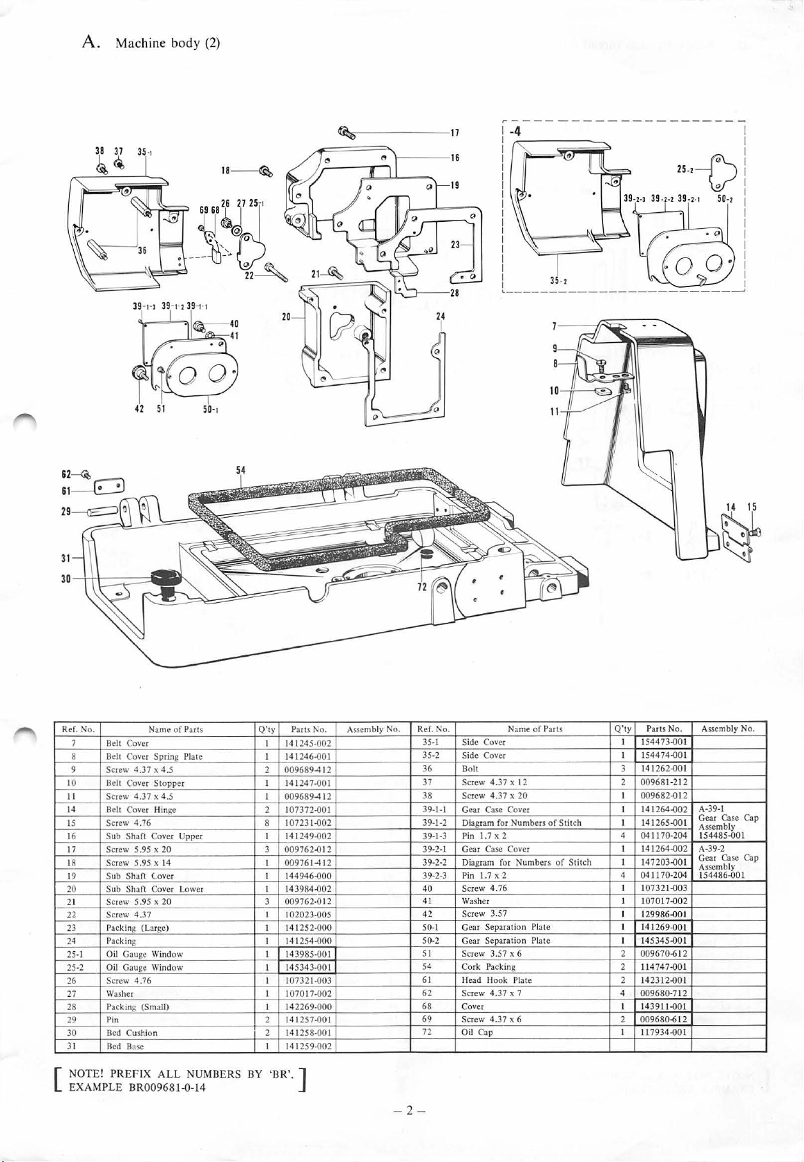
A. Machine body
(2)
18
~
,
:------
17
-4
51
50-
28
- - ---- - - -
-------
---------'
t
Ref. N
o.
Belt
7
Belt
8
9 Screw 4.37 x
10
Belt Cover
II
Screw
14
Belt Cover Hin
Screw
IS
Sub
16
7 Screw 5.95 x
I
18 Screw 5.95 x 14 I
19
Sub
Sub
20
21 Screw 5.95 x 20 3
Screw
22
Packing (Large)
23
24 Packing I
25-1 Oil Gauge Wind
Oil Gauge
25-2
Screw
26
Wa
27
28 Packing (Small) I 142269-000
29 Pin 2
30
Bed Cushion 2 141258-001
31
Bed Base
NOTE! PREFIX ALL NUMBERS
[
EXAMPLE
Name
of
Cover
Cover Spring Plate
4.37 x 4.5
4.76
Shaf
Shaft
Shaft Cover Lower
4.37
4.76
sher
Parts
4.5
Stopper
ge
t Cover Upper I
20
(.over
ow
Window I
BR00968HH4
Q'ty
I
141
141246-{)01
I
2
009689
I 141247-001
I
009689
2 107372-{)01
1
8
14 1249-{)02
3 009762-{)12
00976
144946-{)
I
143984-{)02
I
009762-0
I
102023-005
141252-{)00
I
141254
I 143985-{)01
145343-001
I 107321.{)03
I
1070
141257-{)0 1
I 141259-{)02
BY
'BR
'.]
Parts No.
07231-{)02
245-002
-41
-41
1-412
00
12
-{)00
17-002
2
2
Assembly
No.
Ref. No. Name
-
2-
Side Cover I
35-1
35-2
Side
36 Bolt 3
37 Screw 4.37 x 12 2
38 Screw 4 .37 x
1-1 Gear Case Cover I
3939-1-2 Diagram for Numbers of Stitch I 141265-{)01
39-1-3
39-2-1 Gear Case Cover
39-2-2
39-2
-3
40
4 1 Washer
42
50-I
50
-2
5 1
54 Cork Packing
6 1 Head Hook Plate 2 142312-{)01
62
68
69
72
Cover
1.7 X 2 4 041170-
Pin
Diagram f
Pin 1.7 x 2 4
Screw 4.76 I
Screw 3.57
Gear Separation
Gear Separation Plate
Screw 3.57 x 6 2
Screw 4 .37 x 7 4 009
Cover
Screw
4.3
Oil
Cap
or
7 x 6
of
20
Numbers
Plate
Parts
of
Stitch I
Q'ty
Parts No.
154473-{)01
I 154474-{)01
14126
2-{)01
009681-212
009682-{)12
I
141
264-{)02
I 141264-{)02 A-39-2
147203-{)01
0411 70-204 154486
1
073
1
07017-{)
I
I 1
299
I 141269-{)01
145345-{)01
I
009
670-612
11474
2
680
143911-{)0
I
2
009680-612
I
11
7934.{)01
204
21-{)03
02
86.{)01
7-{)0
·7 12
A-39-1
Gear Case Cap
Assembly
15448
Gear Case Cap
Assembly
1
1
Assembly No.
5-{)01
-{)01
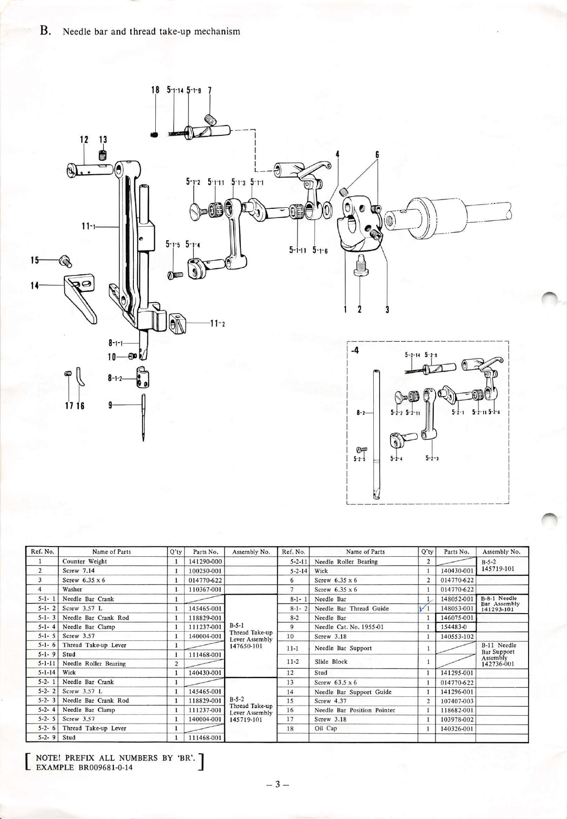
B. Needle ba r
and
thread take-up
mechan
ism
1
~
14
~
n
17 16
1 Ill
--,
I
I
I
I
L-
-
4
r----
I -4
8-l
6
3
-------
----
-------
,
Ref. No. Name of Parts Q' ty Parts No.
I
Co
unt
er
2 Screw 7.
3 Screw 6.35 x 6
4
5-
I-
I
5-I - 2
5-1- 3 Needle Bar Cra
5-I-
4 Need le Bar Clam p
5
-l-
5 Screw 3.57
5-
1- 6 Thread Take-up Lever
5-l-
9
5-1-11
5-
1-14 Wick
5-2- I
5-2- 2
5-2- 3 Needle Bar Crank Rod
5-2- 4
5-2- 5
5-2- 6 Thread Take-up Le
5-2- 9
NOTE! PREFIX ALL NUMBERS
[
EXAMPLE
Weight
14
Washer
Needle Bar Crank
Screw 3.57 L
Stud
Needle Roller Bearing
Needle Bar Cra
Screw 3.57 L
Nee
dle
Screw 3.57
Stud
nk
Rod
nk
Bar Clamp
ver
BR009681-0-14
I 141
I 1
I 0
I 110367.()01
I
I 145465.{)01
I
I
I
I
I 111468.()01
2
I
I
I
I
I 1
I
I
I
---
BY
'BR'.
290
00250
14
770-622
--
11
8829.{)01
111237
140004.{)
--
1
404
--
1
45465
--
118829.()
11
237.{)01
14
0004.()01
111468.()0 1
]
.()00
.()01
.{)01
30.()
-001
Assembly No.
B-5-1
Th
read Take-up
01
Lever Assembly
147650-101
01
B-5-2
01
Th
read Take-up
Lever Assembly
14
5719-101
---
------
f.
No.
Re
5-2-
Needle
11
5-2-14
Wi
6
Screw 6.35 x 6 2
7
Scr
8
-1
-
I
Needle B
8-1-2
Needle Bar Thread Guide
8-2
Needle Bar I
Needle Cat. No. 1955
9
10
Screw 3.18 I 140553- 1
Needle Bar Supp
Il-l
11
-2
Slide Blo
12
Stud I
13
Screw 63.5 x 6
14
Needle Bar Support Guide I
Screw
15
Needle Bar Position Pointer I 118682.{)01
16
Screw
17
Oil
18
-
3-
Name
of
Parts
Roller Bearing 2
ck
ew
6.35 x 6 I 014 770-622
ar
.{)1
ort
ck
4. 37 2 107407.{)03
3.
18 I 103978
Cap
----
--------~
Q'ty
I 140430.()01
--
014
14
1,..-
~/I
148053.()01
146075.{)01
I 15
I
I
------
141
-------
I 014770-622
141
14
I
Parts No. Assembly No.
B-5-2
145719-101
770-622
8-8-1
8052.{)01
44
83.{)
295
.()
296.()01
.{)0
0326.()01
02
01
Bar
14 12
B-11
Bar Support
Assembly
14
2
Needle
Asse
mbly
93-
101
Needle
2736.()0 1
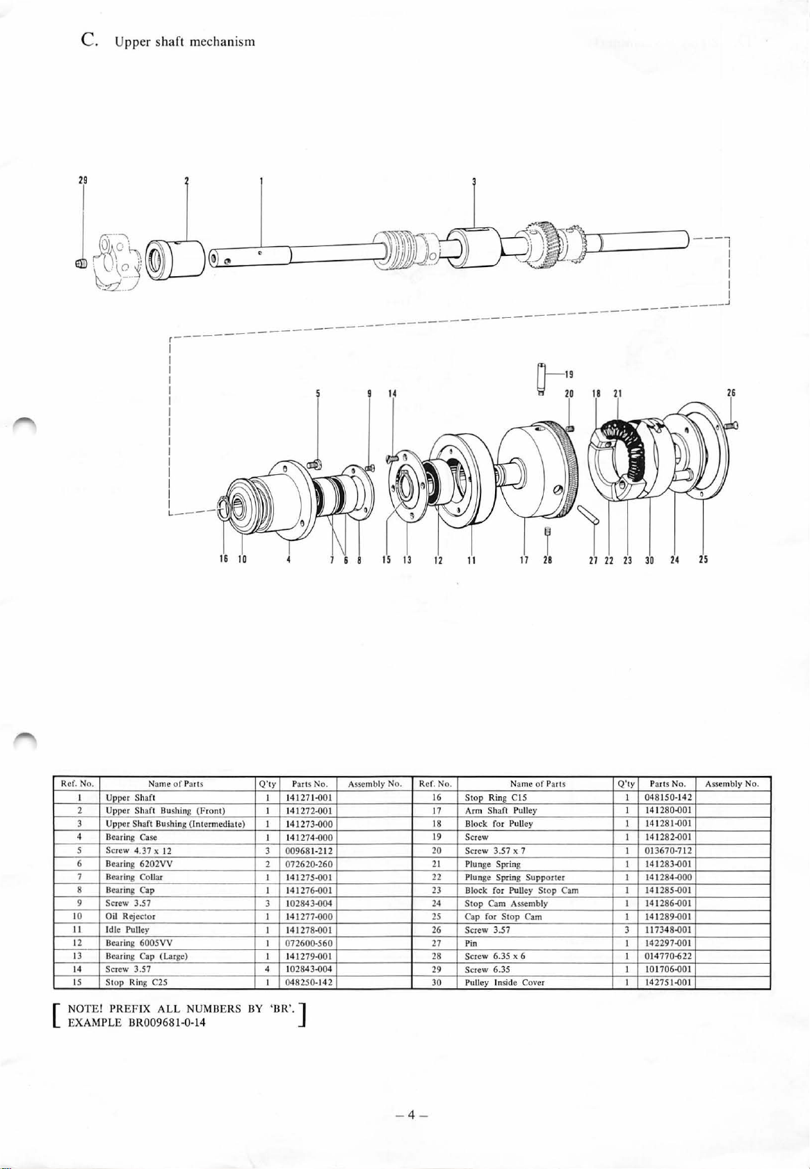
C. Upper sha
ft mechanism
r--
-
-----
-----
-----
n-1
\:;!
------
9
20
~
---------
_________
)
---
,
I
I
I
I
I
.1
Re
f. No.
I
Uppe
2
3
4
r Sha
Uppe
r S
Upper Shaft Bushi ng
Dearing Case
5 Screw 4
Bearing
6
7 Bearing Collar
ear
ing Cap
B
8
9
Screw 3.57
10 Oil Rejecto
II
Idle Pulley I 141278-QOI
12 Dearing 600SVV
13
Dea
ring Cap (Larg
Screw
Stop
3.57
Ring C25
14
IS
Name
of
ft
haft
Bushing (Front)
.37
x 12
6202VV
r
Parts
(Intermediate
e)
Q'
ty
I 14 127 1
I
)
I 1
I 14 1274-QOO
3
2
I
I
3
I 14 1277-QOO
I
I
4 1
I
P
arts No.
-QOI
14
1272-QOI
41273-QOO
00968
1-212
072620-2
1412
75-QOI
6-QO
14127
102
843
-Q04
072600-5
279-QO
141
02843-Q04
048250-14
60
I
60
I
2
Assembly No.
Ref. N
16
17
18
19
20
21
22
23
24
25
26
27
28
29
30
12
o.
11
Stop
Arm
Block f
Sc
Sc
Plun
Plun
B
Sto
Ca
Screw
Pin
S
S
Pulley Inside C
Name
Rin
g CIS
Sh
aft
Pull
or
Pulley
rew
rew
3.57 x 7
ge Spring
ge
Spring Suppor
loc
k for Pulley
p C
am
Asse mbly
p for Stop Cam
3.57
crew 6.35 x 6
crew
6.35
of Parts
ey
Stop
over
ter
Cam
Q'
ty Parts No. Assemb
I
048150-
142
141280-QOI
I
281-QOI
141
I
82
-QO
83
285-QO
41286
8-QO
7-QO
4 770-6
01706-Q
27
5 1-QOI
-QOI
-QO
-QO
22
OI
I
O
I
I
I
I
I
1412
I
013670-712
I
1412
I
141284-QO
I
141
I
1
I
I 141289
11734
3
14229
I
01
I
1
I
14
I
ly No.
NO
TE! PREF
[
EXAMPLE BR00
IX A
LL
968
NUMBERS
1-0-14
BY
'BR'
.]
- 4 -
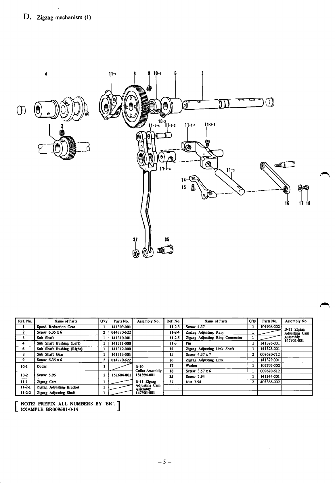
D. Zigzag mechanism (I)
m
Ref. No. Name
1
Speed Reduction Gear
2
Screw 6.35 x 6
3 Sub Shaft
4 Sub Shaft Bushing (Left)
Sub Shaft Bushing (Right)
6
Sub Shaft Gear
8
Screw 6.35 x 6
9
Collar
10.1
Screw
10.2
11-1
11-2-1
11-2-2
NOTE!
[
EXAMPLE BR009681-Q-14
5.95
Zigzag
Cam
Zigzag Adjustint Bracket 1
Zigzag Adjusting Shaft
PREFIX ALL
of
Parts
NUMBERS
Q'ty
1 141309..001
014770-622
2
1 141310..001
1
1 141312..000
141313..001
1
014770-622
2
1
~
2 151604-o01
1
1
BY
'BR,.]
Parts No.
141311..000
---
----
Assembly No.
D-10
CoUar
181994..001
D-11
Adjusting am
Assembly
147901.(}01
----
~
Assembly
Zigz~
35
of
Ref. No. Name
Screw 4.37
11-2-3
11-24
Zigzag Adjusting Ring
Zigzag Adjusting Ring Connector
11-2-5
11-3
Pin 1
Zigzag Adjusting Link Shaft
14
15 Screw 4.37 x 7 2 009680.712
Zigzag Adjusting Link
16
Washer 1
17
Screw 3.57 x 6 1 009670-612
18
Screw 7.94
35
37 Nut 7.94 2 403388..002
Parts
Q'ty
Parts No.
1
104908.002
1
1
----
141326..001
----
141328..001
1
141329.001
1
102707-002
141344.001
1
Assembly No.
D-11
Zigzag
Adjusting Cam
Assembly
147901..001
-5-
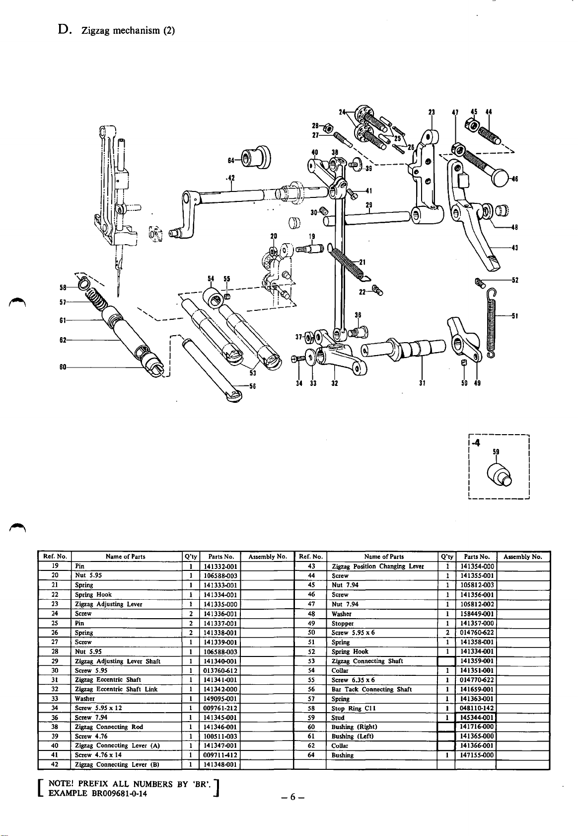
D. Zigzag mechanism (2)
57
··--0
.42
34
33
32
2
23
47
44
49
Ref. No.
19
Pin
Nut 5.95
20
21
Spring
22
Spring Hook
23
Zigzag Adjusting Lever
24
Screw
25
Pin
26
Spring
27
Screw
28
Nut 5.95
Zigzag Adjusting Lever Shaft
29
30
Screw
Zigzag Eccentric Shaft
31
32
Zigzag Eccentric Shaft Link
Washer
33
Screw 5.95 x 12
34
Screw 7.94
36
38 Zigzag Connecting Rod
Screw 4.76
39
Zigzag Connecting Lever (A)
40
Screw 4.76 x
41
42
Zigzag Connecting Lever (B) 1 141348-001
Name
5.95 1
14
of
Parts
Q'ty
Parts No.
1
141332-001
1 106588..()03
1
141333..001
141334..001
1
141335-000
1
2 141336.001
2
141337.001
2 141338-001
1
141339-001
1
106588-003
1
141340.001
013760-612
1 141341.001
141342.000
1
1
149095-001
1
009761-212
1
141345-001
1
141346-001
1
100511-003
141347-001
1
1
009711412
Assembly No. Ref. No.
43
44
45
46
47
48
49
so
51
52
53
54
55
56
51
58
59
60
61
62
64
r--------,
1-4
1
~59
I I
I I
I I
I I
I I
._
________
1 I
Name
of
Zigzag Position Changing Lever
Screw
Nut 7.94
Screw
Nut 7.94
Washer 1 158449.001
Stopper
5.95 x 6 2 01476o.622
Screw
Spring
Hook 1
Spring
Zigzag
Connecting Shaft
CoUar
6.35 x 6
Screw
Bar
Tack Connecting Shaft
Spring
Stop
Ring
Stud
Bushing (Right) 141716-000
Bushing
(Left)
CoUar
Bushing
Parts
C11
Q'ty
Parts No. Assembly No.
141354..()00
1
141355-001
1
105812..003
1
1 141356..001
105812.002
1
141357..000
1
141358-001
1
141334-001
141359.001
141351.001
1
014770-622
1
1 141659-001
141363.001
1
048110.142
1
145344-001
1
141365-000
141366-001
147155-000
1
I
I
..J
NOTE! PREFIX ALL
[
EXAMPLE BR009681-0-14
NUMBERS
BY
'BR'.]
-6-
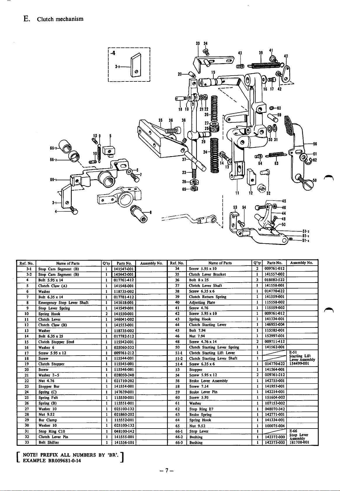
E.
Clutch mechanism
86-1~
66·2~
66-
'---~
'
r---------,
l-4
-[d
I I
I I
1
3-2
I 0 I
I I
l
_________
j
I
I
GJ--60
Ref. No. Name
3-1
Stop Cam Segment (B)
3-2 Stop
4
s
6
7 Bolt 6.35 X
8
9
10
11
12 Clutch Claw (B)
13
14
IS
16
17
18
19
20
21
22
23
24
25
26
27
28 Nut 9.52
29 Bar Clamp
30
31
32
33
Cam
Segment (B)
X
Bolt 5.95
Outch
Washer
Emergency
Stop Lever Spring
Spring
Outch
Washer
Bolt 6.35 X
Clutch Stopper Stud
Washer 6
Screw 5.95 x 12 1
Screw 1
Outch
Screw
Washer
Nut 4.76
Stopper Bar 1
Spring (C)
Spring Felt
Spring (B)
Washer 10 1 025100-132
Washer 10
Stop Ring C10
Clutch Lever Pin
Belt Shifter
14
Claw (A)
14
Stop Lever Shaft
Hook 2 141550-001
Lever
25
Stopper
2-S
of
Parts
Q'ty
Parts No.
1
141547-001
145442-o01
1
017761-412
1
1
141548-001
1 118735-002
017781-412
1
1 141618-001
141549-001
1
146041-D02
1
141553-001
1
118735-002
1
017782-512
1
115542-001
1
025060-332
1
009761-212
115544-001
115545-001
1
115546-001
1
028050-240
1
021710-202
1
141554-001
147639-001
1
1
115550.001
1
11SSS1-001
1
021860-202
115552-001
1
1 025100-132
048100-142
1
1 141555.001
141556-101
1
Assembly No.
--~
-
..
:::::-
..
-
__....___
-·
Ref. No.
34 Screw 5.95 x 10
35
36
37
38
39
40
41 Screw 4.76
42
43
44
45 Bolt 7.94
46
48
so
51-1
51-2
51-4
53
54
56
58
59
60
61 Washer
62
63
64
65
66-1
66-2 Bushing
66-3
I
I
I
I
·-~--p~·.
·'---m-
Outch
Bolt 8
Outch
Screw 6.35 x 6
Clutch Return Spring
Adjusting Plate
Screw 5.95 x
Spring Hook
Outch
Nut 7.94
Screw 4.76 x 14
autch
autch
Outch
Screw
Stopper
Screw 5.95 x 12
Brake Lever Assembly
Screw 7.14
Brake Lever
Screw
Stop Ring
Brake Spring
Spring Hook
Nut 9.52
Stop Lever
Bushing
_....,.I
Name
10
Pin
E7
I
'.J
of
. ..L--Y, I
Lever Bracket
X
25
Lever Shaft
Starting Lever
Starting Lever Spring
Starting Lift Lever
Starting Lever Shaft
6.35 x 6
5.95
Parts
11
Q'ty
Parts No.
009761-012
2
141557-002
1
3 018082-522
1 141558-001
014770-622
1
141559-001
1
1 115558-002
115559-002
1
1 009761-012
1 141334-001
146955-D04
1
1 115585-001
1 152997-001
009711-412
2
1 141562-001
1
1
----
014770-622
1
----
1 141564-001
009761-212
2
142755-001
1
141953-001
1
142214.()01
1
1
151604-002
1 107153-002
1 048070-342
142771.001
1
141334.()01
1
1 100075-004
1
142372.()00
1
----
142373-000
1
Assembly No.
E-51
Starting Lift
Lever Assembly
154499-001
E-66
Stop
Lever
Assembly
181708-001
NOTE!
[
EXAMPLE BR009681-0-14
PREFIX ALL
NUMBERS
BY
'BR'.]
-7-
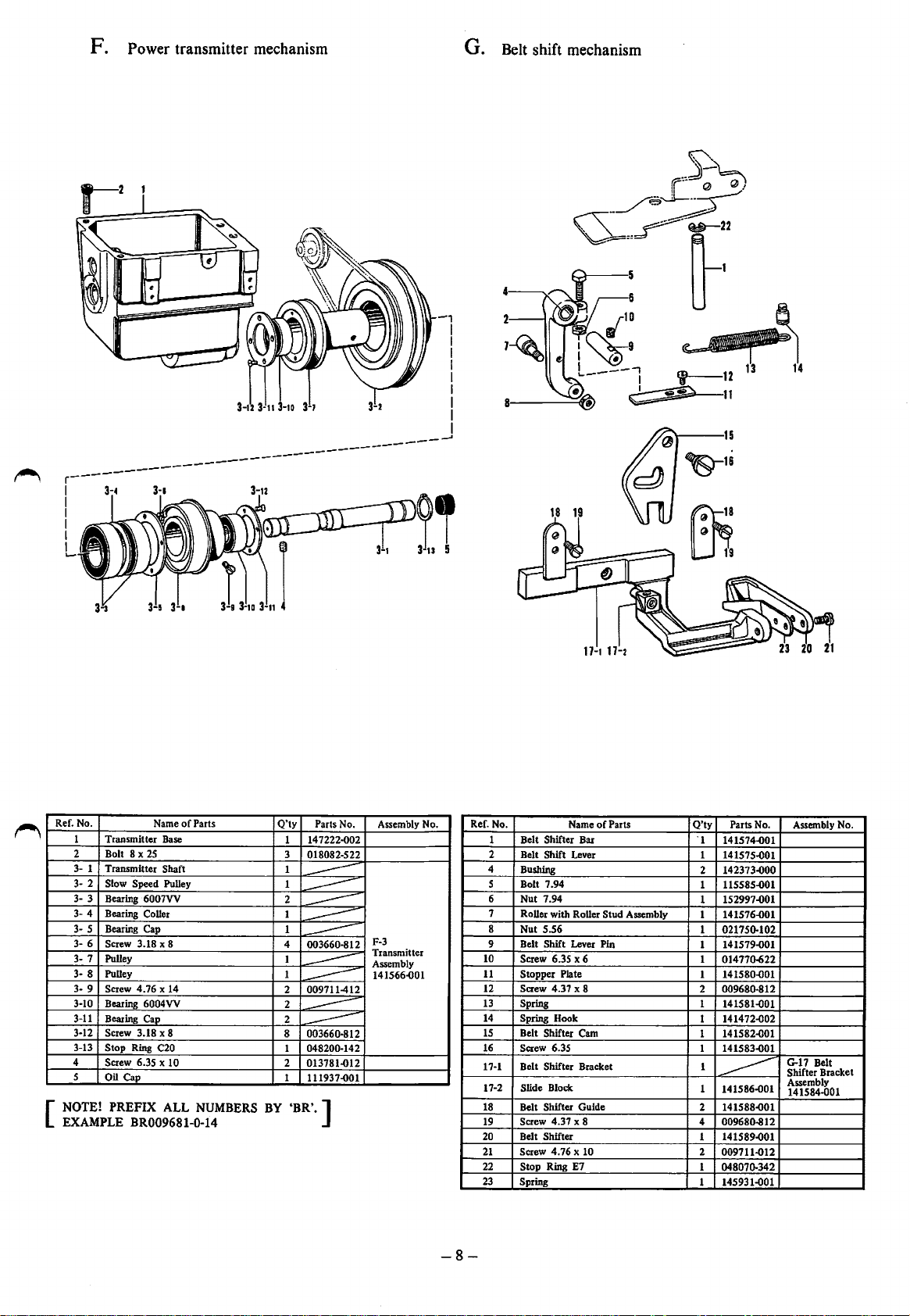
F. Power transmitter mechanism
G.
Belt shift mechanism
Ref. No.
Transmitter
1
2 Bolt 8 x
3-
1
Transmitter
3-
2 Slow Speed Pulley
3-
3
Bearing
3-
4
Bearing
3-
5 Bearing Cap
3-
6
Screw 3.18 x 8
Pulley
3-
7
3-
8 Pulley
3-
9 Screw 4.76 x 14
3-10
Bearing 6004VV
3-11
Bearing
3-12
Screw 3.18 x 8
3-13
Stop Ring C20
4 Screw 6.35 x 10
5
Oil Cap
NOTE! PREFIX ALL
[
EXAMPLE BR009681·D-14
Name
Base
25
Shaft
6007VV
Coller
Cap
of
Parts
NUMBERS
Q'ty
1 147222..002
3
018082-522
1
1
----
2
----
1
----
1
----
003660-812
4
----
1
1
----
2
009711-412
----
2
2
----
8
003660-812
----
1 048200-142
2
013781..012
1
111937..001
BY
'BR'.]
Parts No.
Assembly No.
F-3
Transmitter
Assembly
141566{101
18 19
Ref. No.
Shifter Bar
Belt
1
2
Belt
4 Bushing
5 Bolt 7.94
6
7
8
9 Belt Shift Lever Pin
10
11
12 Screw 4.37 x 8
13
14
15
16
17-1
17-2
18
19
20
21
22
23
Shift Lever
Nut 7.94
Roller with Roller
Nut 5.56
Screw 6.35 x 6
Stopper Plate
Spring
Spring Hook
Belt Shifter Cam
Screw 6.35
Belt Shifter Bracket
Slide Block
Belt Shifter Guide
Screw 4.37 x 8
Belt Shifter
Screw 4.76 x 10 2 009711..()12
Stop Ring E7
Spring
Name
of
Parts
Stud Assembly
Q'ty
Parts No. Assembly No.
'1
141574..001
1
141575.001
142373.000
2
115585.001
1
152997.001
1
1
141576..001
021750.102
1
1 141579..001
1
01477o-622
141580{101
1
2
009680.812
1
141581.001
1
141472.002
1 141582.001
1
141583.001
1
~
1
141586.001
2
141588..001
4
009680-812
1 141589.001
1
048070.342
1 145931.001
G-17
Belt
Shifter Bracket
Assembly
141584-001
-8-
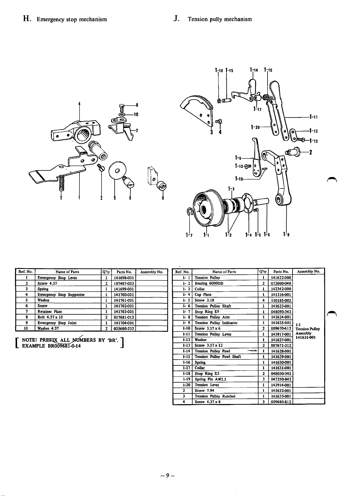
H. Emergency stop mechanism
Tension pully mechanism
J.
Ref. No.
1
Emergency
2 Screw 4.37
3 Spring
4 Emergency Stop Supporter
Washer
5
Screw
6
Retainer
7
8 Bolt 4.37 X 10
9 Emergency Stop Joint
10
Washer 4.37
NOTE!
[
EXAMPLE
Name
Stop Lever
Plate
PR~TX
ALL mfMBERS
B~~~4-·
of
Parts
Q'ty
1
141698.001
2
107407.003
1 141699.001
1
141700.001
141701.001
1
1
141702.001
1 141703.001
2
017681.012
1
141704.001
2
02568Q-232
BY
•BR'. ]
Parts No.
1-7
Assembly No. Ref. No.
111111- 6
111- 9
1-10
1-11
1-12 Washer
1-13
1-14
1-15
1-16
1-17 Collar 1 141631..()01
1-18 Stop Ring E3
1-19
1-20
2
3
4
1-4
Name
of
Shaft
Pawl
W2.S
Parts
~
Shaft
Tension Pulley 1
1
Bearing
2
3
4
5 Screw 3.18
7 Stop Ring E9
8
6000DD
Collar
Cap
Plate
Tension Pulley
Tension Pulley Arm
Tension Pulley Indicator
3.57 x 6 2
Screw
Tension Pulley Lever
Screw 3.57 x 12
Tension Pulley
Tension Pulley Pawl
Spring 1
Spring Pin A
Tension Lever
Screw 7.94 1
Tension Pulley Ratchet 1
·screw 4.37 x 8
1-s
1-&
Q'ty
141622..()00
072600..()40
2
142342.000
1
1
141316.001
4
110185.002
1 141623.001
048090-342
1
1 141624.001
1 141625..()01
00967Q-612
1
143917.001
141627.001
1
2
007671-212
1
141628-001
1 141629..()01
14163().()01
2
04803Q-342
2
04725o-842
1
143914.001
141632.001
141633..()01
009680-812
3
1-a
Parts No.
Assembly No.
J-1
Tension Pulley
Assembly
141621.001
-9-
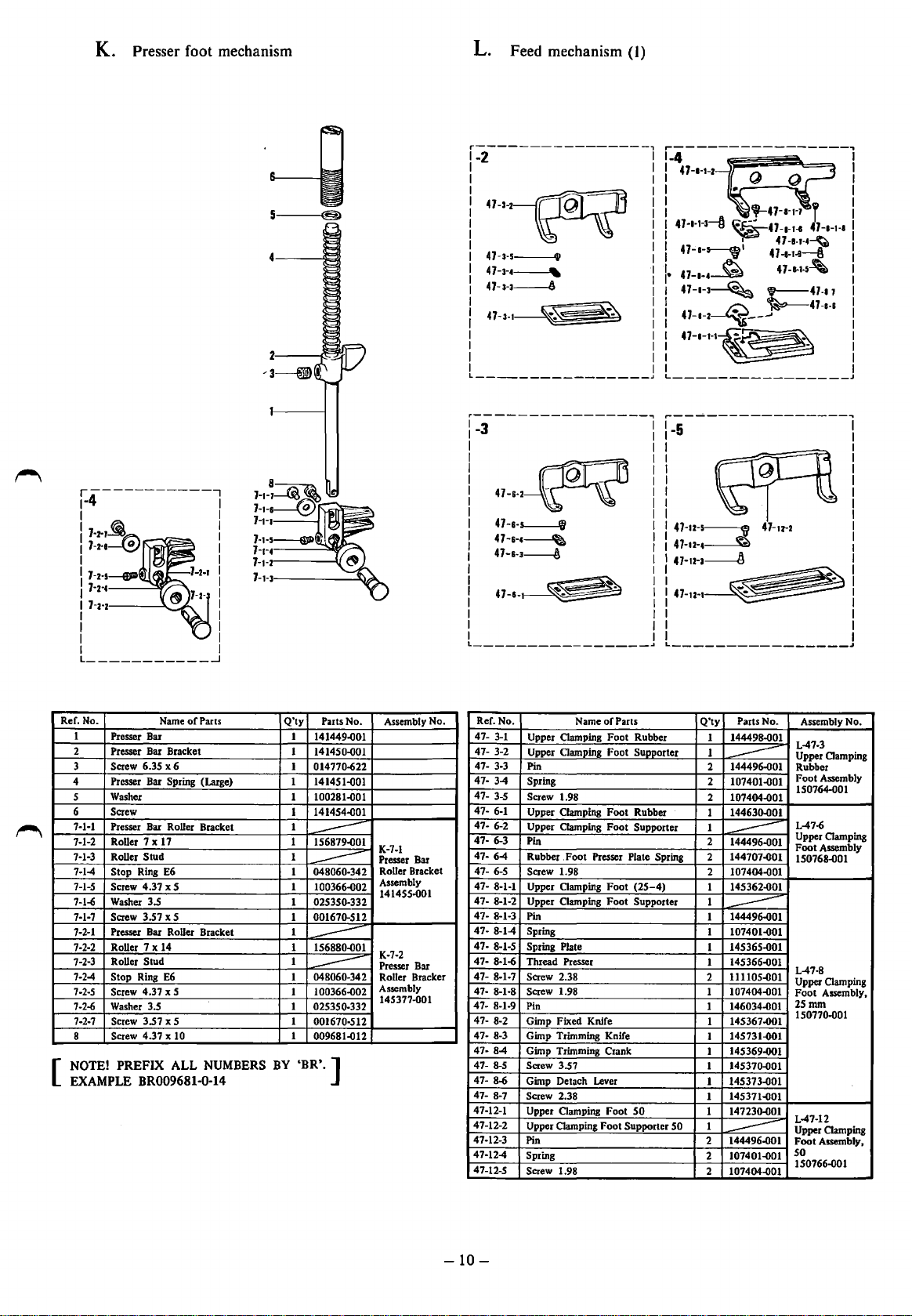
K. Presser foot mechanism
5---(§>
L. Feed mechanism
r=2---------------~
47-1~
4 7
·3·5------i
47·3-4~
47·3-3~
47-3-1
_______________
~
%
(I)
I
I
I
I
I
I
47+1·3--ft
I
I
47-•-5-jl'
I
·I
-1-4~
47
I
47-1·3~
I
I
I
47-1·2~---'
I
I
47-1-1·1~
I
I
J
•
_,_47-a-1·7
~47-a-r-s
I
~
~
l
47-a-1-1
47-1-J-4~
47-e-t-9~
47-1-1·5-'
.-47-17
~47-a-s
r------------,
1-4
I
17·2-J~
1
7-N~~::;:~F-,~~
I
17-N-EJID
l 7·2-4----=:toy
I
7·2-2---~~~
I
I
I
I
L
___________
Ref. No.
1
Presser
2 Presser
Screw 6.3S x 6
3
Presser Bar
4
Washer
s
6
Screw
7-1-1
Presser Bar Roller Bracket
7-1-2 Roller 7 x 17
Roller Stud
7-1-3
7-1-4
Stop Ring E6
7-1-S
Screw 4.37 x S
7-1-6
Washer 3.5
7-1-7
Screw 3.S7 x S
7-2-1
Presser Bar Roller Bracket
Roller 7 x 14
7-2-2
Roller
7-2-3
7-2-4
Stop Ring
7-2-S
Screw 4.37 x S
7-2-6 Washer
7-2-7
Screw 3.S7 x S
Screw 4.37 x 10
8
NOTE! PREFIX ALL
[
EXAMPLE
/~
of
Name
Bar
Bar
Bracket
Spring (Large)
Stud
E6
3.S
BR009681-0-14
...J
Parts
NUMBERS
Q'ty
Parts No.
1
141449.001
1 1414SQ-001
1
014170-622
1 1414S1.()01
100281.()01
1
1414S4.()01
1
1
1 1S6879.()01
----
1
1 048060-342
---
1 100366.()02
1 02S3SQ-332
00167Q-S12
1
1
1 1S6880.()01
---
1
048060-342
1
---
1 100366.002
1
02S3S0-332
1
001670·S12
1 009681.()12
BY
'BR'. ]
Assembly No.
K-7-1
Presser Bar
Roller Bracket
Assembly
1414SS-Q01
K-7-2
Presser Bar
Roller Bracker
Assembly
14S377-001
r~J--------------~
rr=ror:l3
47-&·2----r
47-&-5-.f&l
47-&-c~
47-&-3-----l\
I I
L----------------.J
Ref. No.
47-
3-1
47- 3-2
47474747-
47- 6-2
47- 6-3
47- 6-4
4747- 8-1-1
47- 8-1-2
47- 8-1-3
47- 8-1-4
47·
47- 8-1-6
47- 8-1-7
4747- 8-1-9
47- 8-2
47·
474747- 8-6
47- 8-7
47-12-1
47-12-2
47-12-3
47-12-4
47-12-5
Upper Clamping Foot Rubber
Upper Clamping Foot Supporter
3-3
Pin
3-4
Spring
3-S
Screw 1.98
6-1
Upper Clamping
Upper Clamping Foot Supporter
Pin
Rubber .Foot Presser Plate Spring
6-S
Screw 1.98
Upper Clamping
Upper Clamping Foot Supporter
Pin
Spring
8-1-S
Spring Plate
Thread Presser
Screw 2.38
8-1·8 Screw 1.98
Pin
Gimp Fixed Knife
8-3 Gimp Trimming Knife
8-4
Gimp Trimming Crank
8-S
Screw 3.S7
Gimp Detach Lever
Screw 2.38
Upper Clamping Foot
Upper Clamping
Pin
Spring
Screw 1.98
Name
~
of
Foot
Foot
Foot
Parts
Rubber
(2S-4)
SO
Supporter
~--~-------------~
-5
I
I
I
I
I
I
I
I
I
I
I
I
I
I
I
I
I
I
Q'ty
Parts No. Assembly No.
144498.()01
1
1
144496.()01
2
---
107401.()01
2
2 107404-001
14463Q-001
1
1
2
144496-001
----
144707..()01
2
107404-001
2
14S362.()01
1
1
144496.()01
1
----
1 107401-001
14S36S-001
1
14S366-001
1
11110S.()01
2
107404.()01
1
146034..()01
1
14S367-001
1
14S731.()01
1
1 14S369-001
14S37Q-001
1
1 14S373-001
1 14S371.001
14723Q-001
1
SO
1
144496-001
2
----
107401-001
2
2 107404-001
L-47-3
Upper Clamping
Rubber
Foot
Assembly
1S0764-o01
L-47-6
Upper
Clamping
Foot
Assembly
1S0768-001
L-47·8
Clamping
Upper
Foot
Assembly,
2Smm
150170.()01
L-47-12
Upper Clamping
Foot
Assembly,
so
1S0766-001
-10-
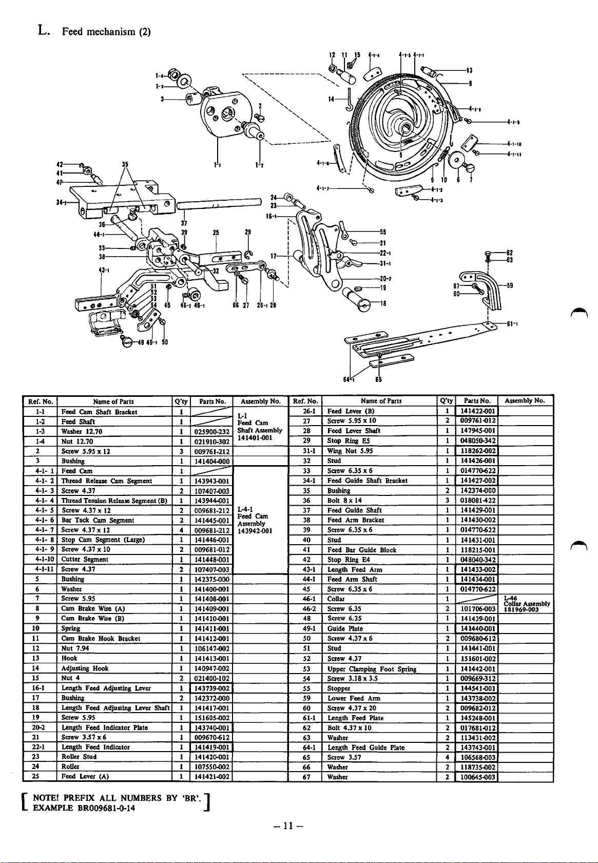
L. Feed mechanism
(2)
....
'-----,4·•·•
Ref. No. Name
1-1
Feed
1-2
1-3
1-4 Nut 12.70
2
3
4-1- 1
4-1- 2
4-1- 3
4-1- 4
4-1- 5
4-1- 6
4-1- 7
4-1- 8 Stop Cam Segment (Large)
4-1- 9
4-1-10
4-1-11
5 Bushing
6
7 Screw 5.95
8 Cam Brake
9
10 Spring
11
12 Nut 7.94
13 Hook
14 Adjusting Hook
15 Nut 4
16-1
17 Bushing
18 Length Feed Adjusting Lever Shaft
19
20.2
21
22-1
23 Roller Stud
24
25
Cam
Feed
Shaft
Washer 12.70 1
Screw 5.95 x 12
Bushing
Feed
Cam
Thread Release
Screw 4.37
Thread Tension Release
Screw
Bar Tack
Screw 4.37 x
Screw 4.37 x 10
Cutter Segment
Screw 4.37
Washer
Cam Brake
Cam
Brake Hook Bracket
Length Feed Adjusting Lever
Screw 5.95
Length
Screw 3.57 x 6
Length Feed Indicator
Roller
Feed Lever (A)
of
Parts
Shaft Bracket
Cam
Segment
4.37 x
Cam
Wire
Wire
Feed Indicator Plate
Segment (B)
12
Segment
12
(A)
(B)
Q'ty
Parts No.
1
1
----
025900.232
----
1
021910.302
3
009761-212
1
141404..000
1
1 143943..001
----
2
107407..003
143944-001
1
2 009681-212
2
141445..001
4
009681-212
1
141446..001
2
009681-012
1
141448-001
2
107407-003
142375-000
1
1 141400001
1
141408-001
1
141409-001
1
141410..001
1
141411..001
141412-001
1
106147-002
1
1
141413..001
1
140947..002
2
021400.102
1
143739..002
2 142372..000
1
141417..001
1
151605-002
1 143740-001
1
00967o-612
1
141419-001
1
141420-001
1
107550-002
1
141421-002
Assembly No. Ref. No.
L-1
Feed
Cam
Shaft
Assembly
141401.001
L-4·1
Cam
Feed
Assembly
143942..001
26-1
27
28 Feed Lever
29 Stop Ring
31-1
32
33
34-1 Feed Guide Shaft Bracket 1 141427..002
35
36
37 Feed Guide Shaft
38
39
40
41
42
43·1
44-1
45 Screw 6.35 x 6 1 014770-622
46-1
46-2
48
49-1 Guide Plate 1 141440..001
so
51
52
53 Upper Clamping Foot Spring
54
55
59
60
61-1 Length Feed Plate
62
63 Washer 2
64-1 Length Feed Guide Plate 2
65
66
67
Q'ty
Name
of
Feed Lever (B)
Screw 5.95 x 10
Wing
Nut 5.95 1 118262..002
Stud
Screw 6.35 x 6 1 01477o-622
Bushing 2
Bolt 8 x 14
Feed Arm Bracket
Screw 6.35 x 6 1 014770-622
Stud
Feed Bar Guide Block
Stop Ring E4
Length Feed Arm 1 141433-002
Feed Arm
Collar 1
Screw 6.35 2
Screw 6.35 I
Screw 4.37 x 6
Stud
Screw 4.37
Screw 3.18 x 3.5 1 009669-312
Stopper
Lower Feed Arm
Screw
4.37 x 20 2
Bolt 4.37
Screw 3.57 4
Washer
Washer
Parts
Shaft
ES
Shaft 1 141434..001
X 10
Parts No.
1
141422..001
2 009761..012
1 147945..001
1
048050.342
1 141426..001
142374..000
018081-422
3
1 141429..001
141430.002
1
1 141431..001
1
118215..001
1
048040-342
101706..003
----
I4I439-001
00968o-612
2
1 141441..001
I
151601..002
1 141442..001
1 144541..001
1 143738..002
009682-012
1
145248..001
2 017681..012
113431..002
143743..001
106568..003
118735..002
2
2
100645..003
Assembly No.
L-46
Collar Assembly
181969-003
NOTE!
[
EXAMPLE
PREFIX ALL
BR009681-0-14
NUMBERS
BY
'BR'.]
-11-
 Loading...