

Page 1

Form K6542
(365)
SINGER
SERVICE MANUAL
331K1 and 331K4
*A Trademark of THE SINGER COMPANY
THE SINGER COMPANY
© 1962 by The Singer Company
Copyright Under International Copyright Union
All Rights Reserved under Inter-American Copyright Union
Printed in Great Britain
Page 2

CONTENTS
PAGE
DESCRIPTION...............................................................3
LUBRICATION AND CLEANING...................................4
INFORMATION FOR OPERATION
Bed Slide (Slide Plate)
Belt Guard......................................................................3
Bobbin and Bobbin Case
Bobbin Winder..................................................
Capacity of Machine...................................................3, 12
Centralizing Feed Dog
Common Causes of Stitching Troubles
Description of Oil..........................................................4
Dimensions of Machine..................................................3
Drawing Up Bobbin Thread............................................8
Feed Dog
Feed, Reverse......................................................... 3, 10
Feed Timing
Graduated Stitch Indicator
Knee Lifter..................................................................... 3
Length of Stitch
Light Fixture....................................................................3
Link Take-up ..............................................................3, 6
Lint, Removal of Excess.................................................4
Machine Dimensions.................................................... 3
Machine Pulley...........................................................3, 11
Needles
Needle Bar.........................................................3, 12, 13
Needle Setting............................................................... 5
Needle to Shuttle, Clearance.
Perfect Stitch..................................................................8
Preparation for Sewing...................................................8
Presser Bar
Presser Bar Guide Bracket
Presser Foot
Pressure of Presser Foot
Pulley........................................................................ 3, 11
.................................................................
................................................................
..........................................................................
.................................................................
......................................................
...................................................
...........................................
.................................................
...........................................
........................................................
..........................................
.........
.........................
..........
.........................
....
............................13, 16
3, 12, 15
................................
4-11
7-9
4, 7
16
15, 16
15
10
3, 10
12
12
9, 15
INDEX
8
5
5
PAGE
ADJUSTMENTS
PARTS LIST
Reverse Feed
Rotary Tension................................................................3, 9
Setting Up Machine....................................................... 3
Shuttle
.....................................................................
Shuttle to Needle Clearance
Specifications............................................................3,12
Speed.............................................................................3
Starting to Sew...........................................................8, 11
Spillage, to Avoid............................................................7
Stand..............................................................................3
Stitch Indicator..............................................................10
Stitch Length
Stitch Type
Stitching Troubles, Causes of
Stop Motion...................................................................11
Table...............................................................................3
Tacking.........................................................................10
Take-up Lever
Take-up Lever Guard
Tension, Check Spring
Tension, Threads.............................................................8, 9
Thread
............................................................................
Threading, Bobbin Case.................................................7
Threading, Upper (Needle).............................................6
Throat Plate................................................................3, 16
Treated Material, Speed when Sewing
Treadling Procedure
Turning a Corner
Twist of Thread............................................................. 5
Unwinder
Upper Threading.............................................................6
Winder (Bobbin)...............................................................4, 7
.....................................................
.................................................................
..........................................................
...................................
................................................................
.....................................................................
........................................
.................................................................
.....................................................
.................................................
..........................
....................................................
........................................................
.........................................................................
12-16
3, 10
13, 14
13, 16
.8
17
10
3
5
3, 6
3
14
5
3
11
3, 6
Page 3

DESCRIPTION MACHINE 331K4:
Machines 331K1 and 331K4 produce top quality,
single-needle, straight-line lock stitching in suits, shirts,
skirts and other clothing.
MACHINE 331K1:
Stitch Type #301.
Central bobbin.
Short beak, oscillating shuttle on horizontal axis.
Link take-up.
Thread take-up lever guard.
Drop feed.
Hinged presser foot 161066.
Feed dog 149603.
Similar to Machine 331K1, with the following
exceptions;
Spring-biased, quick reversible feed mechanism
permits operator to feed work backward or forward
at will.
Solid presser foot 12144.
Feed dog 149304. Throat plate 12414.
INSTALLATION
Before placing the machine in its cut-out on table,
see that the four cushioning pads are at the four cor
ners of the cut-out. Place the machine on these pads.
SPEED
Throat plate 26606.
Length of stitch controlled by regulator thumb screw
on front of machine arm.
Maximum stitch length—5-1 /3 to the inch.
Front, intermediate and rear plain bearings.
Clamp type needle bar.
Tapped hole and seat in rear of arm provided for
mounting light fixture independently of presser bar
lifting lever hinge screw.
Needle bar stroke is 1.472 inches.
Clearance under presser foot is 5/16 inch.
Machine dimensions; Bed length 18-3/4 inches,
width 7 inches.
Belt guard 174112 available on order.
Knee lifter 139625 regularly supplied.
The maximum speed for these machines is 2200
stitches per minute, according to the material sewn
and the type of work being done.
It is advisable to operate these machines at a more
moderate speed the first few days, after which they
can be operated at maximum speed.
Reduce speed of machine when sewing closely
woven fabrics or treated materials.
MACHINE PULLEY
Machine pulley 139724 (solid discs, balanced) has
an outside diameter of belt groove of 2.90 inches
for 3/8 inch V-belt. Effective diameter for 5/16 inch
round leather belt is 2-5/16 inches.
When in operation, the top of the machine pulley
must always turn over toward the operator.
Page 4
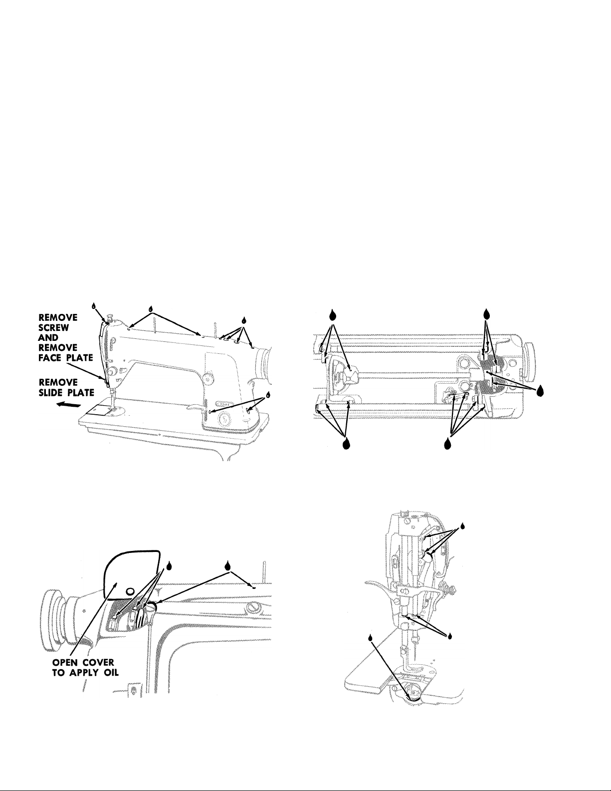
LUBRICATION AND CLEANING
Use SINGER* OIL, “TYPE B” or “TYPE D”. Use
“TYPE D” OIL when an oil is desired which will
produce minimum stain on fabrics.
A machine in continuous use should be oiled fre
quently. Frequency is dependent upon the speed at
which the machine is operated and the type of work
being done. Basically the machine needs oiling at
least twice each working day.
Before starting the machine, at the beginning of the
day and again after the midday recess, apply a few
drops of oil at each of the oiling points on the machine.
Arrows indicate oiling points in Figs. 2 through 5.
Never attempt to oil shuttle race (See Fig. 5) through
holes in throat plate.
BOBBIN WINDER LUBRICATION
Oil bobbin winder occasionally by applying a few
drops of oil to oil wick in bobbin winder frame, as
instructed in
Fig. 11, page 7.
CLEANING
Clean out all lint and abrasive matter from around
the shuttle and between the feed rows on the under
side of the throat plate.
Close all covers after oiling and cleaning. Wipe off
excess oil from surfaces of machine that may come in
contact with material.
Fig. 2. Oiling Points—Front View
Fig. 3. Oiling Points—Rear View
Fig. 4. Oiling beneath Machine Bed
Fig. 5. Oiling Points behind Face Plate and in Shuttle Race
Page 5
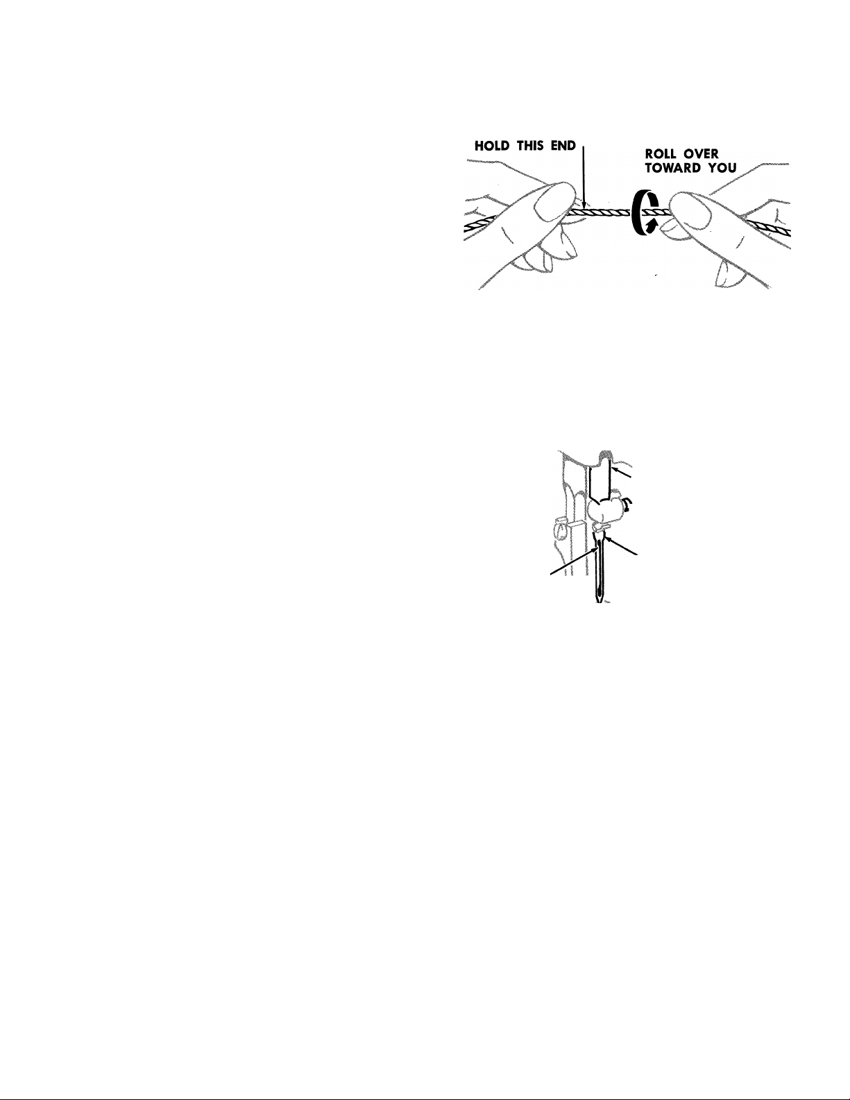
THREAD
On Machines of Class 331K, use only left twist
thread in the needle. Either right or left twist thread
can be used in the bobbin.
To determine the thread twist, hold the thread as
shown in Fig. 6. Then twirl the thread over toward you.
If the strands of the thread wind tighter, the thread is
left twist, if the strands unwind or separate, the thread
is right twist. Rough or uneven thread, or thread which
passes with difficulty through the eye of the needle,
will interfere with the successful use of the machine.
NEEDLES
The needle you select will have a very direct effect
on the quality, strength and appearance of the stitch
produced by the machine.
In selecting a needle size . . . the eye must be large
enough to allow the thread you are using to pass
through freely without binding or chafing. A simple
test is to thread a short length of thread through the
eye of the needle selected; hold the thread taut in a
vertical position and twirl the needle about the thread.
If the size is correct, the needle should slip down the
thread easily.
Needles for this machine are of Catalog #2055
(16 X 87) in Sizes 8 to 14, 16 to 19 and 21 to 25.
Fig. 6. How to Determine the Twist
MOVE TO
HIGHEST POINT
N
LOOSEN SCREW
INSERT NEEDLE UP
LONG
GROOVE It
AS FAR AS POSSIBLE
AND TIGHTEN SCREW
Orders for needles must specify the Quantity
required, the Size number, also the Catalog number.
For example:
‘nOO Size 16, Catalog #2055
(16x87) Needles’’
For best results always use SINGER needles.
TO SET THE NEEDLE
Turn the machine pulley over toward you until the
needle bar moves to its highest point.
After loosening needle clamping screw, remove old
needle and insert new needle UP into needle bar AS
FAR AS IT WILL GO, as instructed in Fig. 7.
The single continuous groove of the needle MUST
face away from the shuttle point (toward the left end
of the machine, as shown in Fig. 7) with eye of needle
directly in line with arm of machine.
Securely tighten needle clamping screw.
Fig. 7. Setting the Needle
COMMON CAUSES OF STITCHING TROUBLES
Check needles often to make sure these defects are
not present...
^ Wrong needle for thread and material in use.
• Bent needle, clogged needle eye, or dirty
needle grooves may cause skipped stitches.
• Hook or burr on needle point may cause picking
or fraying of the material.
• Incorrect setting of needle.
Page 6
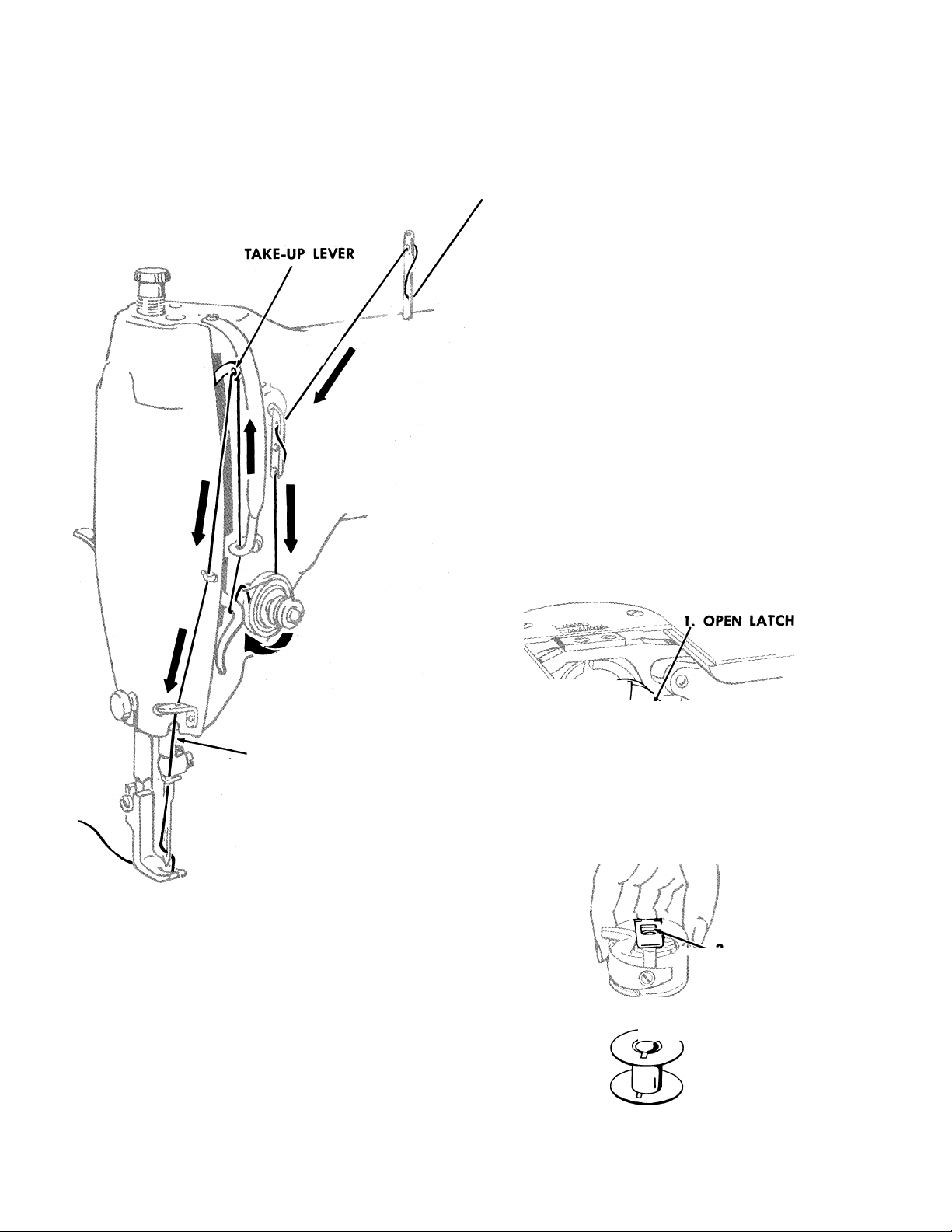
UPPER THREADING
NOTE: Thread unwinder 225258 is recommended for
use with these machines.
First, turn the machine pulley over toward you until
needle is at its highest point, then pass the needle
thread from the unwinder through the threading points
in the order shown in Fig. 8.
Pass the thread from left to right through needle eye.
Draw about two inches of thread through the eye of
the needle with which to start sewing.
TO REMOVE THE BOBBIN
Turn machine pulley over toward you until needle
thread take-up lever is at highest point, as shown in
Fig. 8.
Reach beneath bed of machine with left hand and
remove bobbin from shuttle body, as instructed in
Fig. 9.
While latch is kept open, bobbin will be retained
in bobbin case.
To remove bobbin from bobbin case, release latch
and turn the open end of bobbin case downward.
Bobbin will drop out, as shown in Fig. 10.
MOVE NEEDLE BAR
TO HIGHEST POINT
Fig. 8. Upper Threading
HOLD LATCH AND
\r PULL CASE FROM
A SHUTTLE
""/A.)
Fig. 9. Removing Bobbin Case and Bobbin from Machine
I —o. RELEASE
LATCH
4. BOBBIN
DROPS OUT
Fig. 10. Removing Bobbin from Bobbin Case
Page 7

TO WIND THE BOBBIN
(See “STOP MOTION DEVICE” for
treadle machines on page 11)
Bobbin winder should be fastened to table with its
driving pulley approximately 1 /4 inch in front of the
machine belt. Bobbin winder driving pulley will then
make firm contact with machine belt when thumb latch
is pressed down. Bobbin winder pulley will be released
from contact with belt when sufficient thread has been
wound upon the bobbin.
Place bobbin on spindle, pushing it on as far as it
will go and pass thread through threading points, as
shown in Fig. 11.
Wind end of thread around the bobbin a few times
in the direction shown in Fig. 11. Press down on thumb
latch, pushing driving pulley over against belt.
OIL
LOOSEN TO ADJUST^
FOR EVEN WINDING ^
NOTE—TIGHTEN FOR
MORE THREAD ON BOBBIN
Fig. 11. Winding the Bobbin
SLOTn
TENSION /
CONTROL ^
1. PLACE BOBBIN
ON SPINDLE
2. WIND THREAD
3. PRESS DOWN
Start the machine.
Bobbins can be wound while the machine is stitching.
TO AVOID SPILLAGE: Regulate bobbin winder to
stop automatically when bobbin is wound approx
imately
1/16 inch short of bobbin rim.
TO THREAD THE BOBBIN CASE
Hold the bobbin so that the thread will unwind in the
direction shown in Fig. 12.
Hold the bobbin case as shown in Fig. 12 and place
thé bobbin into it.
Pull the thread into the slot 1, Fig. 13 and under the
tension spring 2, Fig. 13.
Draw the thread into the delivery eye at the end of
the tension spring, as shown at 3, Fig. 14.
TO REPLACE THE BOBBIN CASE
r--
Fig. 12. Placing Bobbin in Bobbin Case
1. PULL THREAD
INTO SLOT
2. DRAW THREAD
DOWN AND
UNDER SPRING
Fig. 13. Pulling the Thread into the Slot
3. TURN BOBBIN
CASE OVER
AND DRAW
.THREAD UP INTO
DELIVERY EYE
Fig. 14. Drawing the Thread Under the Tension Spring
After threading, take bobbin case by latch in the
left hand.
Place bobbin case on centre stud of shuttle body
with position finger pointing upward, in front of notch
in upper plate over shuttle race, as shown in Fig. 15.
Release latch.
Press bobbin case back until latch catches groove
near end of stud.
Allow about two inches of thread to hang free.
Fig. 15. Bobbin Case Threaded and Replaced
Page 8

Fig. 17. Perfect Stitch
TO PREPARE FOR SEWING
Hold slack end of needle thread loosely and turn
machine pulley over toward you until needle moves
down and up again to its highest point, catching bobbin
thread.
• Draw up needle thread; bobbin thread will come
up with it through hole in throat plate, as shown in
Fig. 16.
• Lay both threads back under presser foot.
• Close the bed slide.
• Always keep the bed slide closed when the
machine is in operation.
TO START SEWING
• Move take-up lever to top of its stroke as shown
in Fig. 8, page 6.
• Place material beneath the presser foot. Lower
the presser foot. Start to sew, turning the machine pulley
over toward you.
TO TURN A CORNER
• Stop the machine when needle is rising but before
it is out of the material.
• Raise the presser foot.
• Turn material for next line of stitching, using needle
as a pivot.
• Lower the presser foot.
• Resume sewing.
• Avoid aiding the machine by pulling the fabric,
lest you damage the needle. The machine feeds the
work without assistance.
Fig. 18. Too Tight Needle Thread Tension
TO REMOVE THE WORK
• Stop the machine with the take-up lever at top of
its stroke.
• Raise the presser foot.
• Draw the work toward the rear until it is clear of
the needle.
• Cut the threads close to the goods.
• Lay the threads back under the presser foot.
THREAD TENSION
For ordinary stitching, tension on needle and bob
bin threads should be balanced with needle and
bobbin threads locked in centre of thickness of
material as shown in Fig. 17.
When there is too much tension on needle thread and
not enough on bobbin thread, needle thread cannot be
pulled down into material, as required. Poor stitching
results.
Needle thread will lie on top of material as
shown in Fig. 18.
When there is too much tension on bobbin thread and
not enough on needle thread, you get the reverse of
the condition shown in Fig. 18. The stitching is just as
poor. The bobbin thread will lie on bottom of mate
rial as shown in Fig. 19.
Page 9

REGULATION
BOBBIN THREAD TENSION:
For average sewing, tension on bobbin thread should
be very light.
To regulate tension on bobbin thread, remove the
bobbin case and turn screw in tension spring, as in
structed in Fig. 20.
^When tension on bobbin thread has been correctly
adjusted for ordinary stitching, the required stitch
can usually be obtained thereafter to suit the work in
process by varying the tension on needle thread
only.
NEEDLE THREAD TENSION:
To avoid accumulating excessive tension on needle
thread, first obtain correct tension on bobbin thread, as
instructed above.
Regulate needle thread tension only when
presser foot is down (since needle thread tension is
automatically released when presser foot is raised).
Fig. 20. Regulating Bobbin Thread Tension
Tension on needle thread should be just enough to
set stitch correctly in material.
Having lowered presser foot, turn thumb nut at the
front of tension discs either over toward right or left, as
required. See instructions in Fig. 21.
PRESSURE OF PRESSER FOOT
ON THE MATERIAL:
The correct presser foot pressure helps feed the
work efficiently. You can regulate the amount of pres
sure exerted by the presser foot on the material by
means of the thumb screw, as shown in
Fig. 22.
The pressure on the material should be as light as
possible, while sufficient to insure correct feeding.
To increase the pressure turn the thumb screw down
ward.
To reduce the pressure turn this screw upward.
The pressure is correct when the work moves steadily
and smoothly without stalling.
Fig. 21. Regulating Needle Thread Tension
MORE PRESSURE
Fig. 22. Regulating the Pressure on the Material
Page 10

1. LOOSEN
THUMB SCREW—
TO CHANGE
STITCH SETTING
2. RAISE OR
LOWER
AS DESIRED.
3. TIGHTEN—
WHEN DESIRED
STITCH SETTING
IS OBTAINED
Fig. 23. Regulating Length of Stitch on Machine 331K1
SHORTER
LONGER
10
REGULATION
LENGTH OF STITCH, ON MACHINE 331K1:
The length of stitch is regulated by moving the
pointer in the stitch indicator plate on the front of the
machine as instructed in Fig. 23.
When pointer is set at 0 there can be no feeding
motion.
Maximum length of stitch is 5Vb stitches per inch.
Move pointer to desired length of stitch and firmly
tighten thumb screw.
LENGTH OF STITCH, ON MACHINE 331K4:
Depress the feed-reversing lever slightly and turn
thumb screw over to the left to lengthen the stitch or over
to the right to shorten the stitch, as instructed in Fig. 24.
2. TURN
THUMB i
SCRiW I for longer
•STITCH
1. DEPRESS
LEVER STITCH
^ 3. RELEASE
LEVER
Fig. 24. Regulating Length of Stitch on Machine 331K4
Thumb screw is marked with numerals from “0” to
“5”.
When thumb screw is set at “0” feed reversing lever
is fixed at central position and there can be no forward
or reverse feeding.
When thumb screw is set at “5”, machine will feed at
maximum stitch length.
REVERSE FEED, ON MACHINE 331K4:
(See instructions in Fig. 25)
Simply depress the feed-reversing lever as far as it
will go.
Feeding in reverse continues only as long as lever is
held in depressed position.
Forward feeding is resumed upon release of lever.
Direction of feed can be reversed at any point in a
seam while machine is in operation, without disturbing
the work. Back tacking is therefore readily accom
plished and ends of seams are easily fastened.
The range of movement of feed reversing lever is
limited by the setting of thumb screw as instructed
above under stitch length regulation.
When lever is released it will rise to highest point
permitted by setting of thumb screw and machine will
stitch forward at the set stitch length.
Fig. 25. Reversing the Feeding Movement
on Machine 331K4
When lever is depressed as far as permitted by the
thumb screw setting, machine will feed in reverse at the
set stitch length.
Page 11

THE STOP MOTION DEVICE
Machine 331K1 and 331K4 are regularly fitted
with solid disc (balanced) machine pulley 139724^
without stop motion device.
When required for treadle operation a machine may
be obtained, on specific order, with machine pulley
139725, including a stop motion device, as shown in
Fig. 26.
This device allows machine pulley to turn without
turning arm shaft so that bobbins ma/ be wound and
correct treadling acquired without disturbing the
stitching mechanism.
To loosen the machine pulley, hold pulley with left
hand and, with right hand, turn the stop motion screw
over toward you, as shown in Fig. 26.
11
Fig. 26. Loosening Machine Pulley
TREADLING
To acquire correct treadling habits, loosen the
machine pulley, as instructed in Fig. 26 and place both
feet squarely but comfortable upon treadle, as instruct
ed in Fig. 27.
Turn machine pulley over toward you by hand and
at the same time, allow your feet to move freely and
lightly with motion of the treadle.
Continue to do this until a regular, easy movement is
acquired and you are able to stop and restart the
machine without the machine pulley turning in
the wrong direction.
Tighten the stop motion screw and practice sewing
until you have become accustomed to the necessary
motion of hands and feet during the actual operation.
Fig. 27. Position of Feet Upon Treadle
NOTE: The instructions on the following pages are for Service Representatives.
To insure correct timing and avoid unnecessary repetition, these instructions should
be followed in the order given.
Page 12

12
SPECIFICATIONS
The following gauge distances should be of help to
adjusters of these machines:
• Height of presser foot above throat plate 5/16
inch.
• Distance from throat plate seat to needle stop in
needle bar (needle bar at lowest point), 1.004 inches.
• Needle bar stroke 1.472 inches
• Rise of needle bar when point of shuttle is at
center of needle (loop lift), .100 inch.
VARIATIONS: Certain conditions of sewing may
necessitate slight variations from thèse settings.
TO SET THE PRESSER BAR
AT THE CORRECT HEIGHT
PREPARATION:
Remove face plate and slide plate.
Accumulation of lint, oil and dirt on presser foot seat
on presser bar may prevent proper seating of foot.
Clean this area before checking and setting the
presser bar.
CHECK:
1. When presser foot is raised with presser bar lifting
lever there should be a 5/16 inch clearance between
presser foot and throat plate.
2. When presser foot rests firmly upon throat plate
(with feed dog below throat plate) there should still be
some clearance between guide bracket A, Fig. 28 and
lifting bracket B, as shown in Fig. 28.
Fig. 28. Checking Height of Presser Bar
3. When presser foot is at its highest point and needle
bar is at its lowest, top of presser foot should clear the
needle thread eyelet C, Fig. 28 at the lower end of
needle bar.
SETTING:
• Release the presser bar lifting lever D, Fig. 28,
lowering the presser foot.
• Loosen clamping screw E, Fig. 28.
• Raise or lower guide bracket A, as required.
• Make certain presser bar is positioned correctly
so that needle will locate centrally between the two
toes of the presser foot.
• Securely tighten screw E.
Whenever guide bracket A, Fig. 28 has been
moved on presser bar, check the setting of check
spring as instructed on page 14.
Page 13

TO SET THE NEEDLE BAR AT THE
CORRECT HEIGHT
PREPARATION:
Remove face plate, slide plate and throat plate. See
that needle is correctly set in needle bar, as instructed
on page 5.
CHECK:
When shuttle point passes centre of needle, top of
needle eye should be approximately 1/16 inch below
point of shuttle. See Fig. 29.
13
A 4 SHUTTLE POINT
CENTER
VW
I
ALTERNATE CHECK:
The gauge distance from throat plate seat to needle
stop in needle bar (at lowest point) should be 1.004
inches, as indicated in Fig. 30.
SETTING:
Loosen clamping screw F, Fig. 30. Raise or lower
needle bar, as required. Then securely tighten screw F.
Replace throat plate, slide plate and face plate.
TO TIME THE SHUTTLE
EXPLANATION:
Timing of shuttle is fixed at the factory for normal
sewing conditions at a 1/10 inch loop lift.
This is accomplished by pinning the shuttle driver at
one end of the oscillating shaft and then pinning crank
G, Fig. 31
at the other end of the shaft at the specified
timing location.
TO CHECK THE TIMING:
Turn the machine pulley over toward you until needle
bar descends to lowest point and then rises approxi
mately 1/10 inch.
At this setting, for normal sewing, the point of the
shuttle should be at the centre of the needle as shown
in Fig. 29.
Fig. 29. Relationship of Shuttle Point to Needle Eye
Fig. 30. Setting Needle Bar Height
TO RE-SET THE TIMING:
When it becomes necessary to replace one or more
of the shuttle driving parts or to alter the timing to suit
a particular sewing condition, remove pin H, Fig. 31.
Loosen set screw J, Fig. 31.
Move point of shuttle to desired timing position and
securely tighten set screw J in crank G.
Plug pin hole in shaft and drill new hole to receive
pin in desired location.
Insert pin H.
Fig. 31. Setting the Oscillating Shaft Crank
to Time of Shuttle
Page 14

Fig. 32. Setting Height of Check Spring
14
HEIGHT SETTING
PREPARATION:
Thread the machine.
CHECK:
Turn machine pulley over toward you slowly. When
take-up lever begins to rise^ spring K, Fig. 32 “checks”,
showing a slight dip and a return to its highest position.
Later, as take-up lever approaches top of stroke,
setting the stitch, this “check” spring K should be drawn
all the way down. As lever descends, check spring K
returns to rest.
TO SET THE CHECK SPRING
SETTING:
To obtain the slight dip in check spring when take-up
begins to rise, loosen screw L, Fig. 32. Turn stud M,
Fig. 32 (at the same time turning entire tension as
sembly) either over toward left to lower the spring’s
resting position and decrease its movement, or
over toward right to raise the spring’s resting
position and increase its movement. Securely tighten
set screw L.
Fig. 33. Adjusting Tension on Check Spring
VARIATIONS (FOR MACHINE 331K4):
Under certain conditions of tacking, it may be neces
sary to set the check spring higher than it is otherwise
normally set.
TENSION SETTING
PREPARATION:
Thread the machine. Securely tighten set screw L,
Fig. 33. Make certain thumb nut is on stud M, Fig. 33.
CHECK:
Tension on check spring K, Fig. 33, should be suffi
cient to ensure action at top speed; but still light
enough to permit itself to be drawn all the way down
before any thread is drawn through the tension discs,
as take-up lever approaches height of stroke.
Check spring setting should be reviewed each time a
different foot is applied to machine.
SETTING:
Using a large screwdriver in slot of stud M, turn stud
either over toward left to decrease tension or over
toward right in increase it, as shown in Fig. 33.
VARIATIONS:
The tension on the check spring may require a
different setting, depending upon the thread and
material used. Heavier thread or bulkier material re
quires more tension to ensure correct thread control.
Page 15

TO TIME THE FEED
CHECK:
Test feed assembly linkage for freedom of move
ment. Action of feed dog must be regular and smooth
for maximum efficiency
15
When the feeding movement is correctly timed
• The feed dog stops moving toward the rear
just as the take-up lever reaches the top of its stroke.
• The feed dog drops below surface of throat
plate just as needle is about to enter material.
TIMING:
• Set the machine for longest stitch as instructed on
page 10.
• Turn up the cover plate at the rear of the machine
arm.
• Loosen set screw N in feed eccentric P, Fig. 34.
• Rotate feed eccentric P as required to obtain
desired timing.
• Securely tighten set screw N.
• Close cover plate at rear of arm.
----------
Fig. 34. Timing the Feed
FULL DEPTH
OF REAR TEETH
TO SET THE FEED DOG AT THE
CORRECT HEIGHT
Before checking height of feed dog, set the machine
for longest stitch, as instructed on page 10.
When the feed dog is at its highest position, ap
proximately the full depth of the rear teeth of the
feed dog should project above the top surface of
throat plate, as shown in Fig. 35.
Variations of feed dog height may be necessary to
balance the height with the presser foot pressure.
To adjust the height of the feed dog, loosen screw
O, Fig. 35 and raise or lower the feed bar R, Fig. 35,
as required.
When the feed dog is set to the desired height,
securely tighten screw O.
/
Fig. 35. Adjusting Height of Feed Dog
Page 16

16
TO CENTRALIZE FEED DOG IN THROAT
PLATE SLOTS
CHECK:
Feed dog should not contact edges of throat plate
slots.
SIDEWISE SETTING:
Feed dog should travel on a line midway between
sides of throat plate slots.
Feed dog can be moved toward left or right, as
required, after loosening two nuts S and screw U, Fig.
36, on screw centres T.
To move feed dog toward left, loosen screw centre
T at left end of shaft V, as required, and tighten the
other screw centre an equal amount.
Make certain that screw centres hold feed rock shaft
V snugly in place without binding. Then securely tighten
both nuts S and screw U.
Fig. 36. Centralizing Feed Dog
LENGTHWISE SETTING:
Set machine for longest stitch as instructed on page
10.
Feed dog should be set so that its movement is
equidistant from front and rear edges of throat plate
slots.
Loosen clamping screw U and move feed bar R and
rock shaft V, as required.
Securely tighten screw U.
TO REMOVE AND REPLACE THE
SHUTTLE RACE
REMOVAL (With needle at highest position):
Remove the two screws W, Fig. 37.
Remove the shuttle race X, Fig. 37, from machine.
Shuttle Y may now be slipped in or out of shuttle race
X without difficulty.
REPLACEMENT (With needle at highest position):
Slip shuttle Y into shuttle race X, Fig. 37. Turn shuttle
in shuttle race so that shuttle will correctly engage
shuttle driver Z, Fig. 37.
Install shuttle race with shuttle in machine.
Fasten with two screws W, Fig. 37.
Tighten two screws W.
Page 17

The Some !
To get replacements
that are the same
as parts in new
machines...
BUY PARTS AND
NEEDLES MADE BY
TO BE DOUBLY SURE...
SINGERS
of new machine performance, make sure that all
replacement parts and needles are precisely
identical to those in new SINGER machines.
Look for the trademark
SINGER
or SIMANCO
O on every package or container
& on the needle or numbered part
TO ALL WHOM IT MAY CONCERN: The improper placing or renewal
of the trademark “SINGER” or any other of the trademarks of The
Singer Company (all of which are duly Registered Trademarks) on any
machine that has been repaired, rebuilt, reconditioned, or altered in
any way whatsoever outside a SINGER factory or an authorised
SINGER agency is forbidden.
Needles in containers marked “For Singer Machines” are NOT made by SINGER.
Page 18

 Loading...