

Page 1
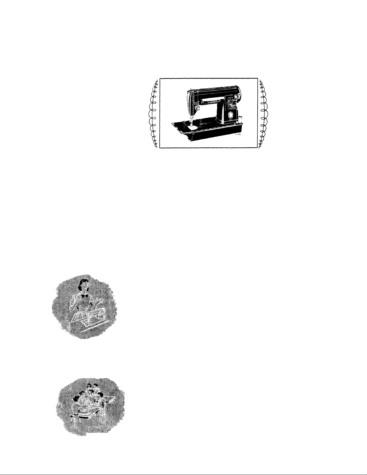
SINGER*
SLANT NEEDLE SEWING MACHINE
...........
represents the ultimate in sewing machine
design and styling. A product of the matchless skill
Form 20542
(Rev. 7-76)
and engineering ability of
SINGER
line of unexcelled Sewing Machines.
301 is an outstanding addition to our long
SINGER
craftsmen, the
Printed in U.S.A.
AS THE OWNER OF THIS ENTIRELY NEW
SINGER SEWING MACHINE:
You have a machine revolutionary in design, but made with
the same care and craftsmanship that have been the hallmark
of SINGER Machines for more than a century. We are acutely
aware that SINGER Sewing Machines have become an Ameri
can tradition and are intensely proud of, and determined to
continue, this heritage.
Your SINGER “301” is the product of this pride, determination
and the unsurpassed technical skill of SINGER. This smooth
running machine-of-tomorrow will amaze and thrill you with
its versatility and ease of operation.
Utilize all the advanced features, combine them with your own
skill and discover a new world of sewing enjoyment. Exclusive
dresses for yourself, clothing for your
family and a multitude of items for your
home will be yours — all at a fraction
of their ready-made cost.
*A Trademark of THE SINGER COMPANY
Copyright ® 1956 by The Singer Co.
All Rights Reserved Throughout the World
m
/f
Page 2
WHAT SINGER SERVICE MEANS TO YOU
Over 1400 SINGER SEWING CENTERS in the United States
alone are fully equipped to serve women who sew.
There you’ll find a wide selection of PATTERNS, BUTTONS,
THREAD, and FINISHING SiRVICES which include COV
ERING BUTTONS, BELTS AND BUCKLES, making BUTTONHOLES, HEMSTITCHING, etc., plus:
You are entitled to sewing lessons when you become the owner
of a new SINGER. A skilled, SINGER-trained teacher per
sonally guides you and assists you in learning the fundamentals
of home sewing. Other courses embracing all phases of home
sewing are available at low cost.
REPAIR SERVICE is as convenient as your telephone. When
ever your machine needs adjustments, a trained, courteous
SINGER representative will gladly call at your home. SINGER*
Service assures excellent workmanship,» guaranteed repairs, and
SINGER* parts. A written estimate is given you in advance
for approval.
And remember, your SINGER SEWING CENTER and the ever
ready SINGER Service Car can be easily identified by the
famous SINGER red “S” Trade Mark.
SINGER 301 FEATURES “AT YOUR SERVICE”
• SMOOTHER STITCHING than ever before
is possible with this new, gear-driven, lock
stitch machine.
• QUIET, fast and efficient — it whispers at
high speeds.
• FULL-VIEW work area. Inclined Needle Bar
places work in your direct line of vision.
• PERFECT CONTROL — even at “hand-
stitch” speeds.
•BALANCED MOTION of the new SINGER
301 prevents vibration.
• EASY STARTING — No coaxing necessary
— lightly press the knee or foot control and
your 301 starts to sew.
• SIMPLE THREADING — no complicated
diagrams are needed.
• REVERSIBLE FEED for sewing either in a
forward or backward direction — easy to back
tack and to fasten ends of seams.
• PREFOCUSED LIGHT illuminates work
ing area—prevents eye strain.
• CALIBRATED STITCH REGULATOR per
mits finger-tip control of stitch length.
• STITCHING GUIDES, with graduated
markings to guide seam width and turn square
corners.
• VERSATILE — use it as a portable or cab
inet machine.
• EASY TO CARRY — convenient handle is
concealed in top of head.
• LIGHT WEIGHT — full-sized aluminum
head weighs only 16 pounds.
Page 3
• SELF-SETTING NEEDLE makes it impos
sible to insert needle incorrectly in clamp.
• FEED THROW-OUT DEVICE permits darn
ing and embroidering without attachments.
• RECESSED BOBBIN WINDER—equipped
with automatic stop — it can’t break or tangle
your thread.
• HINGED BED EXTENSION permits quick
and easy removal of bobbin.
ELECTRICAL INFORMATION
• HINGED FACE PLATE—Simplifies clean
ing and oiling.
• DIAL TENSION takes the guess work out
of upper tension setting.
• FLEXIBLE SPOOL PINS — bend but do
not break—thread unreels smoothly and easily.
•COMPLETELY ENCLOSED motor and
principal working parts insure maximum
safety.
The SINGER"^ electric motor
in your sewing machine is furnished for oper
ation on an alternating current of 110-120
volts, 25 to 75 cycles, or on 110-120 volts
direct current. Special motors can be provided
through your SINGER SEWING CENTER
for direct or alternating current for any volt
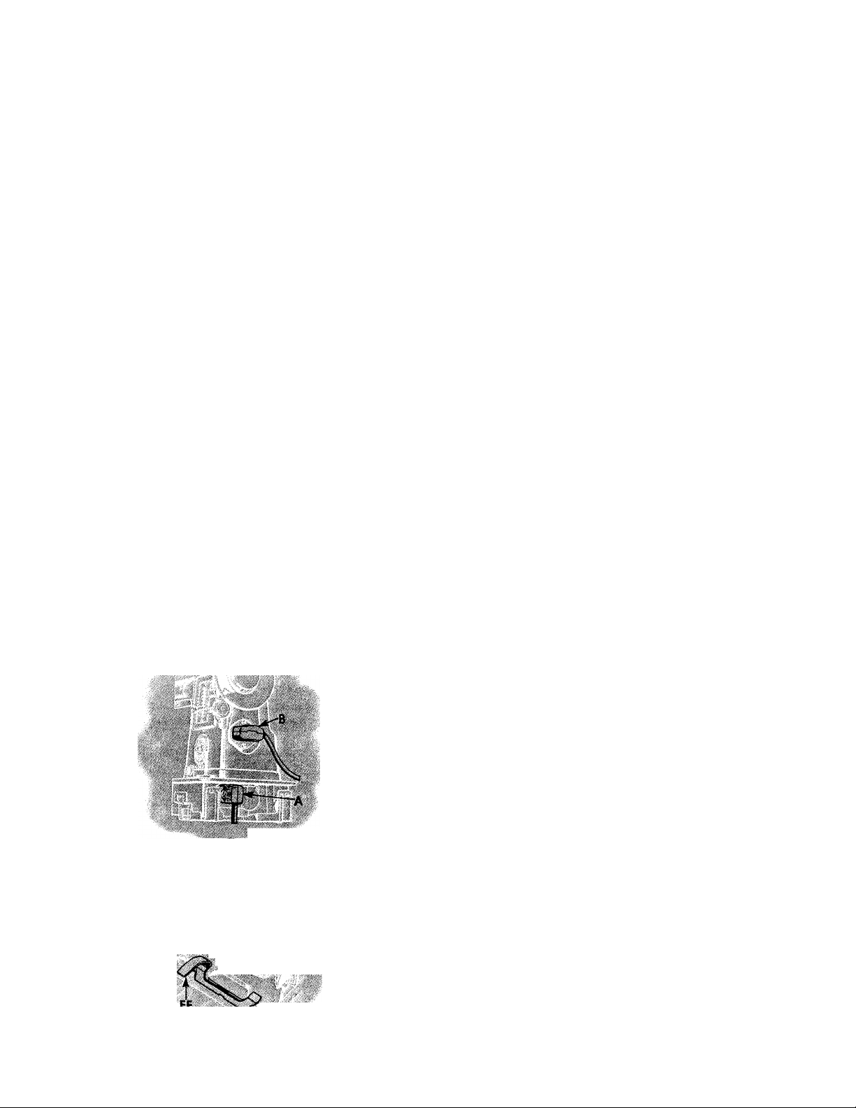
ELECTRICAL CONNECTIONS FOR MACHINE
Push 2-pin terminal plug A, Fig. 1 on 2-pin terminal block at
right end of bed.
Push 3-pin terminal plug B, Fig. 1 on 3-pin terminal block at
right of machine and connect plug at other end of cord to
electrical outlet.
age between 20 and 250, and for 32 volts
direct current.
Before Inserting Electric Plug—
be sure that the voltage and the number of
cycles stamped on the motor nameplate are
within the range marked on your electric
meter installed by your power company.
Fig, 1, Electrical Connections
for Machine
Fig. 2. Showing Latch for Releasing
Machine fron\ Cabinet
Speed Controller
The speed of machine is regulated by amount of pressure on
the pedal of the foot controller or the knee lever.
TO USE THE 301 as a portable machine
To remove the machine from the cabinet, disconnect the 3-pin
terminal plug B, Fig. 1, lift handle C, Fig. 3, raise bed ex
tension at left, depress latch FF, Fig. 2, and lift out machine.
Disconnect 2-pin terminal plug A, Fig. 1 and set machine
aside. Then remove controller from its holder in cabinet by
pulling it downward. With machine set on a suitable surface
near an electrical outlet, reconnect 2-pin and 3-pin terminals
and place foot controller on floor.
Page 4
HANDLE FOR CARRYING MACHINE
To use handle C, turn it up, as shown in Fig.
3, When not in use, turn handle down.
CAUTION: When you have finished your
sewing, always disconnect plug from electrical
outlet.
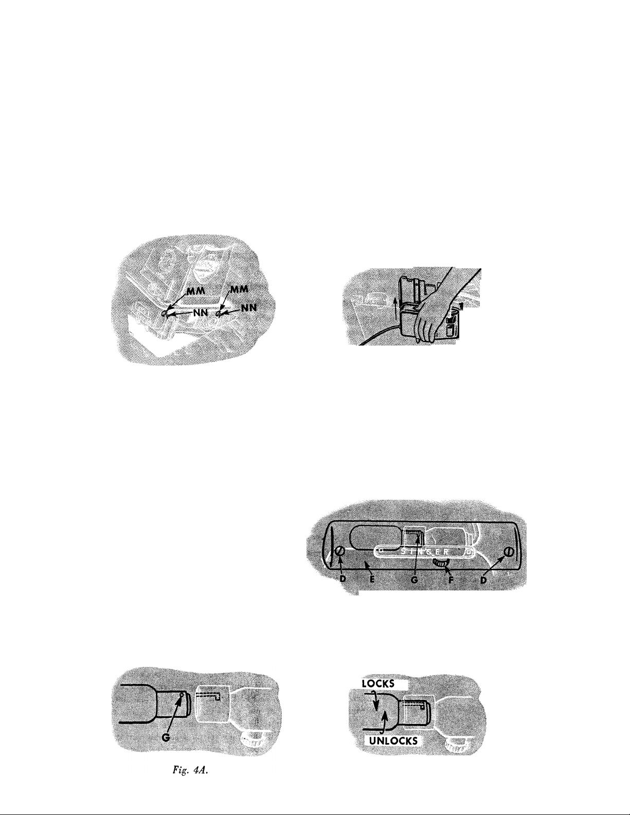
TO REPLACE MACHINE IN CABINET
Disconnect both terminal plugs. Grasping han
dle C, Fig. 3, place machine in cabinet so
that holes MM, Fig. 3A, fit over studs NN in
machine cradle. Press down on left end of ma
chine until latch
FF, Fig. 2, snaps into posi
tion to hold machine in place. Tilt back ma-
Fig. 3. Showing Handle for Carrying Machine
chine with cradle, install controller in side of
cabinet as shown in Fig. 3B, then connect
2-pin terminal. Lower machine to sewing posi
tion and connect 3-pin terminal.
Fig. 3A.To Replace Machine in Cabinet
LIGHT
The Light is turned, “on” or “off” by the
switch F, Fig. 4.
To Remove Bulb. Remove two screws D and
lamp cover E. Do not attempt to unscrew bulb.
Press it into socket and at same time turn bulb
over in direction shown in Fig. 4B to unlock
bulb pin G, then withdraw bulb.
To Replace Bulb. Press new bulb into socket
with bulb pin G, Fig. 4A entering slo jf
socket and turn it over in direction show in
Fig. 4B to lock bulb pin G in position. Replace
lamp cover E and securely fasten it in position
with two screws D.
Fig. SB. Replacing Controller in Cabinet
Fig. 4. Replacing the Bulb
Fig. 4B.
Page 5
NEEDLES AND THREAD
For perfect stitching, thread should be selected
according to fabric to be stitched and needle
must be correct size for thread which must
pass freely through eye of needle.
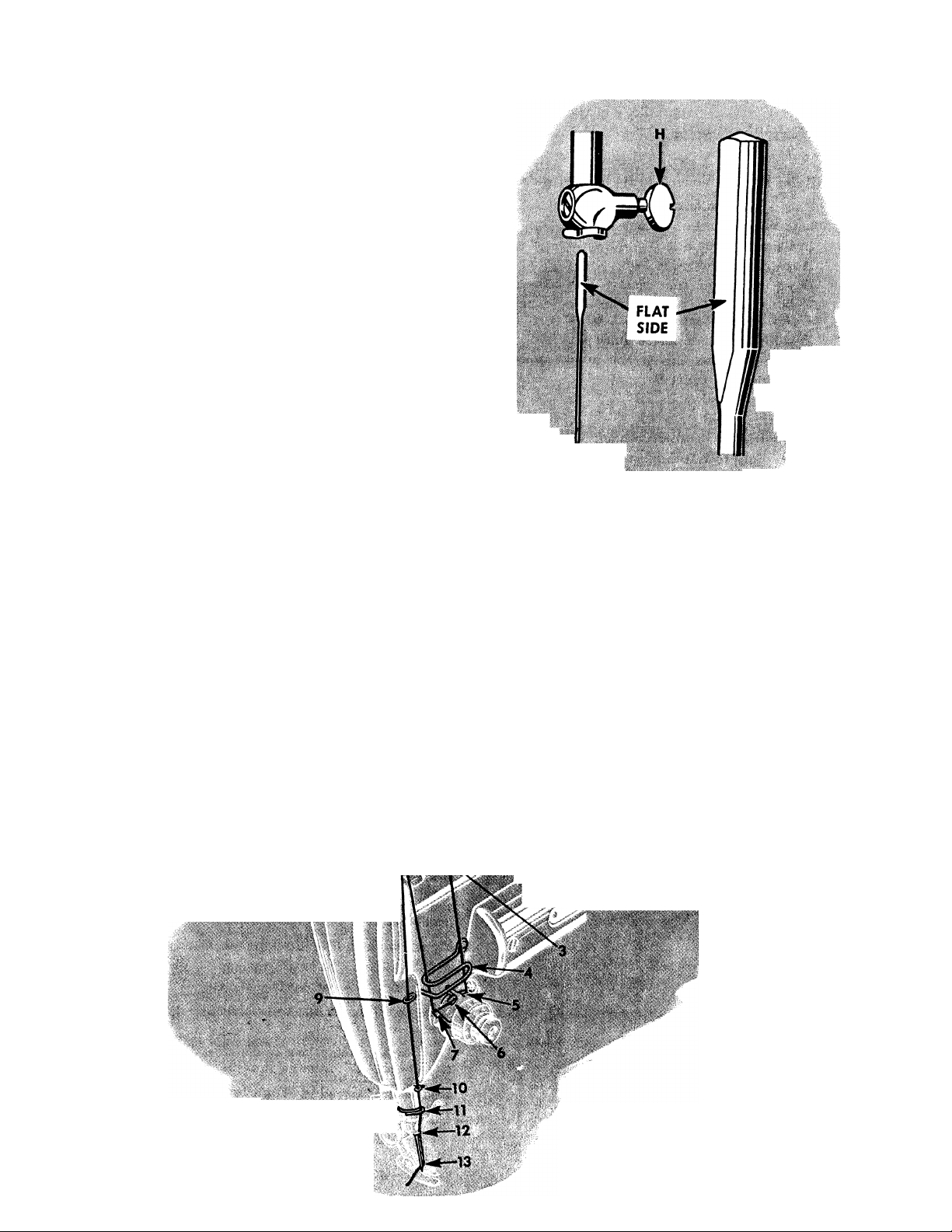
TO SET THE NEEDLE
Select correct needle according to table on
page 70. Be sure that needle is not blunt or
bent. Raise needle bar to its highest position
and loosen thumb screw H in needle clamp.
Push needle with its flat side to left up into
needle clamp as far as it will go, then tighten
thumb screw. As the needle is self-setting, it
cannot be inserted incorrectly in the needle
clamp.
Fig, 5. Setting the Needle
V
V
r '
iO
7‘" d ‘ '
s-' '-/I /1 'f • .
-t V ^ . I.f ,
Fig. 6. Upper Threading
Page 6
11
UP1»ER THREADING
See Figs. 6 and 7
Raise take-up lever 8 to its highest point.
Place spool of thread on spool pin 1
Lead thread into thread guide 2
Into thread guide 3
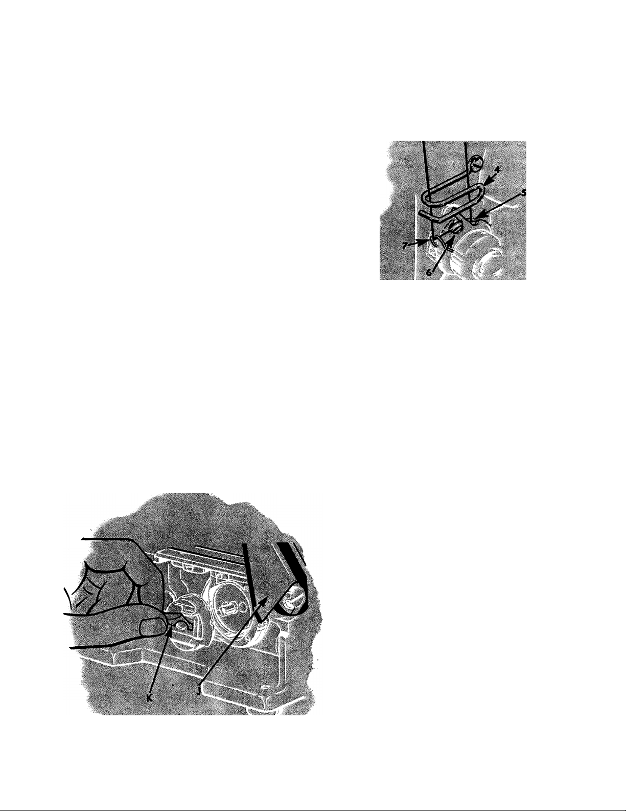
Down into thread guide 4
Down, under and from right to left between tension discs 5
Hold spool tightly and pull thread up against take-up spring
7 until it enters retaining fork 6
Pass thread up into thread guide 4
From right to left through hole in take-up lever 8
Down through eyelet 9
Into wire thread guide 10
Into wire thread guide 11
Into guide 12 on needle clamp
From right to left through eye of needle 13.
Draw about two inches of thread through eye of needle.
Fig. 8. Removing the Bobbin Case
12
TO REMOVE THE BOBBIN
Raise needle to its highest point.
Raise bed extension J. Grasp bobbin case latch
K and lift out bobbin case. Release latch and
remove bobbin.
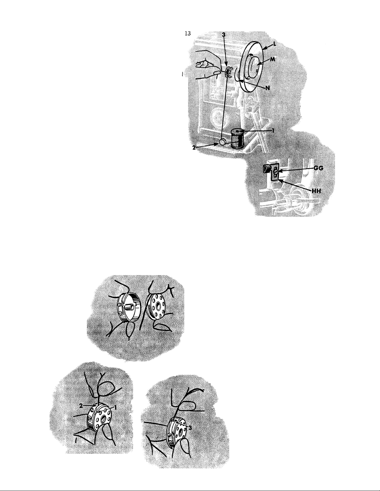
TO WIND THE BOBBIN
See Fig. 9 on the following page
To stop motion of needle, hold hand wheel L
and loosen knurled screw M by turning it over
toward you. Lift bobbin winder out of recess
and bring its pulley N into contact with hub of
hand wheel.
Place bobbin on bobbin winder spindle as far
as it will go.
Place spool of thread on spool pin 1.
Draw thread under and between tension discs
Pass thread through one of the holes in left
side of bobbin 3, from the inside.
Hold end of thread as shown in Fig. 9 and
press controller pedal as for sewing. End of
thread must be held until it is broken off.
Page 7
Allow tension discs to control flow of thread
so that it winds on bobbin in uniform, level
rows.
The bobbin winder will stop automatically
when the bobbin is filled. ^
Remove bobbin from spindle and return bob'
bin winder to its recessed position. Tighten
knurled screw M,
If bobbin does not wind evenly, loosen screw
which holds tension bracket 2 in position and
move bracket to the left if bobbin winds high
on the right; move bracket to the right if
bobbin winds high on the left. When bracket
is properly centered, thread will wind evenly
across bobbin.
If bobbin winds too fully, loosen screw GG,
Fig. 10 and move plate HH, downward,
slightly. To wind more thread on bobbin, move
plate HH, upward, slightly. Tighten screw
GG.
Bobbin can be wound while machine is sewing.
Fig, 9.
Winding the Bobbin
Fig, 10,
Adjustment for
Regulating
Amount of Thread
Wound on Bobbin
Fig. 12
14
Fig.11
TO THREAD BOBBIN CASE
Hold bobbin so that thread will unwind in
direction shown in Fig. 11.
Hold bobbin case as shown in Fig. 11, and
place bobbin into it.
Fig. 13
Pull thread into slot 1, under
tension spring 2 and into slot
3 at end of spring. Allow
about three inches of thread to
hang free from bobbin case.
Page 8
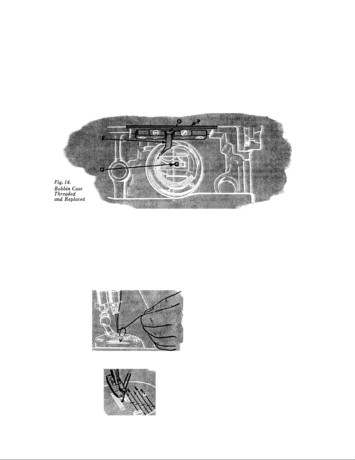
TO REPLACE BOBBIN CASE
15
Hold bobbin case by latch and place it on stud
Q, having thread draw from top of bobbin
case.
Release latch and press bobbin case back until
latch enters groove in stud. Allow about three
inches of thread to hang free from bobbin case
and turn down bed extension.
CAUTION:
If throat plate P is removed for cleaning stitch
forming mechanism, etc., make certain,
when replacing throat plate, that position
finger R, Fig. 14 of bobbin case base enters
notch O, Fig. 14 of position plate attached
to underside of throat plate.
Fig. 15, Drawing Up Bobbin Thread
Fig. 16. Threads in Position to Start Seiving
16
TO PREPARE FOR SEWINO
Hold end of needle thread with left hand and
turn hand wheel over toward you until needle
goes down and up again and thread take-up
lever S, Fig. 17 is at its highest point. Pull
up needle thread and bobbin thread will come
with it, as shown in Fig. 15.
Lay both threads back under the presser foot,
diagonally across the feed, as shown in Fig.
16, to the right or left, depending upon which
side of the needle the material is to be located,
so that when the presser foot is lowered, the
threads will be firmly held between the feed
and the presser foot.
NOTE: On the throat plate, there are distinct
markings to guide the edges of seams and
hems. These markings are at 1/8" intervals
from 1/4" to 3/4" in distance from the right
of the needle, and assist in guiding the fabric
uniformly. The crosslines on the throat plate
indicate the point at which to pivot on the
needle when turning square corners.
Page 9
TO START SEWING
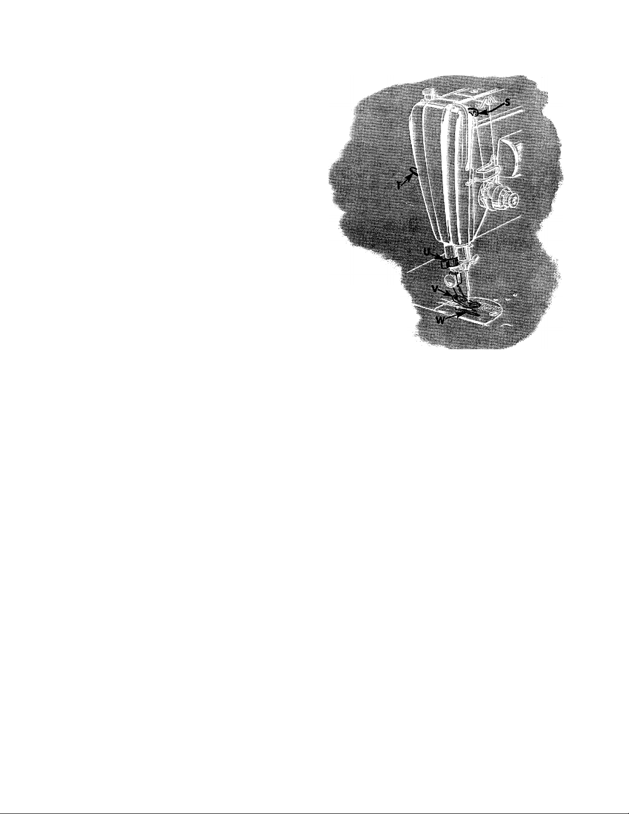
Be sure to have thread take-up lever S
at its highest point.
Place material beneath presser foot V, turn
hand wheel to bring point of needle into fab
ric, then lower presser foot by means of
presser bar lifter T and start to sew. Press con
troller pedal to start machine. The speed de
pends upon amount of pressure on controller
pedal.
Most materials require only guiding for best
sewing results. However, the miracle fabrics
such as nylons, dacrons, orlons, blends with
various rayons, puffed weaves, sheers, jerseys
and tricots, which, by their nature, require light
pressure, also require support in the form of
holding the material taut at the back and front
of the needle as the needle enters the fabric.
This support assures a smooth, even seam.
Never pull the material when sewing.
The machine will sew its own thread when
sewing from one piece of material to another.
However, avoid operating a threaded machine
with presser foot up and without fabric under
the foot.
17
Fig, 17
S. Thread Take-up
Lever
T. Presser Bar Lifter
U. Thread Cutter
V. Presser Foot
W. Feed Dog
TO TURN A CORNER
Pivot on the eye of the needle. Stop machine
when needle is in this position. Raise presser
foot and turn work as desired, then lower
presser foot and resume sewing.
BASTING
The longest stitch, No. 6 on stitch regulator,
adjusted by lever Y, Fig. 18 is found satis
factory for basting. These basting stitches are
easily removed by clipping every sixth stitch
and withdrawing the long continuous thread.
Machine basting is firmer, more even and
much quicker than hand basting.
18
TO SEW BIAS SEAMS
Use a shorter stitch when sewing bias or
curved seams to increase the elasticity of the
seam and to prevent seam failure under strain.
No change in tensions is required.
TO REMOVE THE WORK
Stop machine with thread take-up lever
S, Fig. 17 at its highest point.
Raise presser foot, draw fabric back and to left
and sever threads on thread cutter U, Fig. 17.
Place ends of threads under presser foot, as
shown in Fig. 16.
Page 10
19
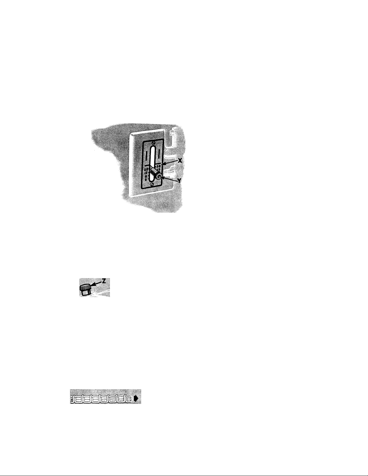
TO REGULATE LEtIGTH OF STITCH
The machine is adjustable to make from 6 to
30 stitches per inch, as indicated by numerals
on stitch indicator plate X.
To change length of stitch, turn thumb screw
on stitch regulator lever Y, away from the
stitch indicator plate X, as far as necessary.
Then move the stitch regulator lever until it
is in line with the desired number of stitches
Fig. 18.
Showing Lever for
Regulating Length
of Stitch and
Reversing Direction
of Feed
to the inch and turn the thumb screw inward
only until it touches the stitch indicator plate.
The machine will now make the indicated num
ber of stitches to the inch in either a forward
or reverse direction, depending on whether the
lever Y is at its lowest or highest position.
TO REGULATE DIRECTION OF FEED
To feed the material from you, push down
the stitch regulator lever Y, as far as it will go.
To feed the material toward you, raise the
stitch regulator lever Y, as high as it will go.
The direction of feed can be reversed at any
point of a seam without removing work from
machine.
The reverse feed makes it easy to “back stitch”
and to fasten ends of seams.
Fig. 19. Thumb Screw for Regulating
Pressure on Presser Foot
i Fig. 20. Perfect Stitching
sfig. 21. Imperfect Stitching
Fig. 22. Imperfect Stitching
20
TO REGULATE PRESSURE ON PRESSER FOOT
For average materials, the pressure of the presser foot seldom
requires changing. Heavy materials require more pressure than
lightweight fabrics. The pressure should be only heavy enough
to prevent side creeping of material and still obtain a uniform
length of stitch. To increase pressure, turn thumb screw Z clock
wise or downward. To lighten pressure, turn thumb screw so
that it screws upward.
THREAD TENSIONS
For perfect stitching, the tension on needle and bobbin threads
must be heavy enough to pull threads to center of thickness of
material and make a firm stitch, as shown in Fig. 20.
Needle Thread lies straight along top side of material, caused
by too heavy tension on needle thread or too light tension on
bobbin thread, as shown in Fig. 21.
Bobbin Thread lies straight along underside of material, caused
by too light tension on needle thread or too heavy tension on
bobbin thread, as shown in Fig. 22.
Page 11
21
TO REGULATE NEEDLE THREAD TENSION
The tension on needle thread can be tested
only when presser foot is down.
The numerals “0 to 9”
on dial D, Fig. 23 in
dicate different degrees
;y| of tension that can be
3o b t a i n e d.
The num
bers do not denote size
of thread or ounces of
tension.
NeedLe I firead 1 ension ,
J 'T • When tension has been
correctly set as de
scribed on pages 23 and 24, note number at
indicator line G so that this setting may be
regained should the tension be altered for
special work.
To increase tension, turn thumb nut B
gradually to right (clockwise) until required
tension is obtained. Each higher number de
notes increased tension.
To decrease tension, turn thumb nut B
gradually to left (counter-clockwise) until re
quired tension is obtained. Each lower num
ber denotes less tension.
The tension indicator G is marked with the
signs -f- and —, which indicate the direction
in which to turn the thumb nut B for more
or less tension.
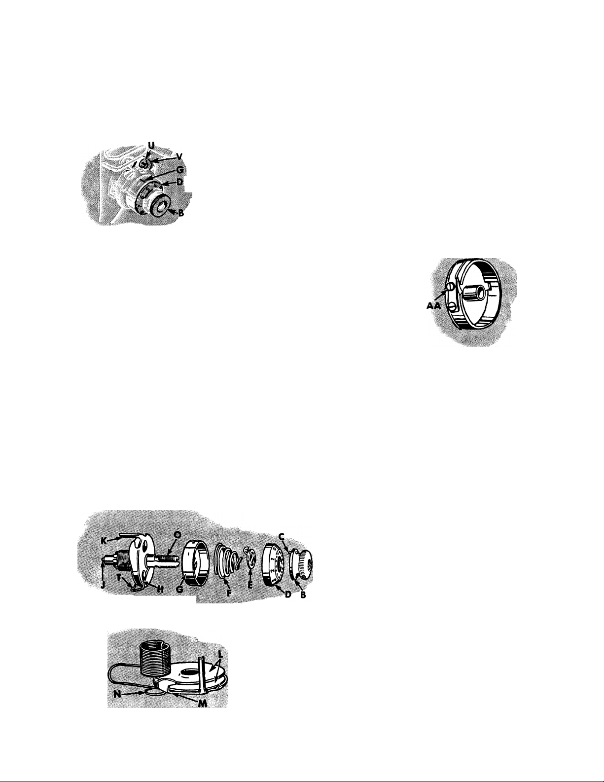
TO REGULATE BOBBIN THREAD TENSION
The tension on bobbin thread is regulated by
screw AA, Fig. 24 which is nearest center of
tension spring on outside of bobbin case. To
increase tension, turn screw AA over to right.
To decrease tension, turn
this screw over to left. ^
When tension on bobbin
thread has been once prop
erly adjusted, it is seldom
necessary to change it, as a
correct stitch can usually be
obtained by varying tension
on needle thread.
Fig. 24. Bobbin Thread Tension
TO REMOVE AND DISASSEMBLE NE 4.E THREAD TENSION
Turn thumb nut B to left (counter-clockwise) until ‘‘O” on
numbered dial stops at cente** bne on indicator G.
Fig. 25. Needle Thread Tension Disassembled
TO REASSEMBLE AND REPLACE NEEDLE THREAD TENSION
Make sure that tension releasing pin J is in place in stud O.
Place two tension discs L with their convex faces together on
tension thread guide M, then pass eyelet N of thread take-up
spring under thread guide, having coils of spring above ten
Fig. 26. Tension Disc Assembly
sion discs, as shown in Fig. 26.
22
To separate pin C in thumb nut B from dial
D, press in dial, unscrew thumb nut and re
move it. Then remove dial, stop washer E,
tension spring F, indicator G and tension
assembly H.
NOTE: It is not necessary to remove stud O
from machine to disassemble the thread ten
sion. It is shown removed in Fig. 25, only
to illustrate the complete assembly.
Page 12

23
Place tension disc assembly on stud O so that extension K
enters hole in machine and tail (inside the coil) of thread takeup spring enters one of grooves in the stud. Next replace indica
tor G, open side out, on stud with plus and minus signs at top
and hold parts, thus assembled, against shoulder of stud. Then
insert tension spring
F in indicator with first (half) coil of
spring straddling lower half of stud. Place stop washer E on
stud with extension S above stud. If spring and stop washer are
in correct position, extension S will clear first (half) of tension
spring, as shown in Fig. 28.
Next, place dial D on stud with No. 2 opposite stop washer ex
tension S, then push dial to compress tension spring and at the
same time screw thumb nut B on stud, inserting pin C on nut
in one of the holes in dial D. Then lower presser bar and turn
thumb nut B to left until on dial D stops at centerline on
indicator G. Thread the tension and pull thread through tension
discs to test amount of tension on thread at the position.
At this point there should be a slight pull on the thread to in
dicate that there is a minimum tension which gradually in
creases with the turning of thumb nut B to the right, provid
ing a full range of tensions with one revolution of the thumb nut.
Fig. 27. Reassembling
Needle Thread Tension
Fig. 28. Stop Washer and Tension Spring
If the pull is too strong for a minimum ten
sion, press in dial D to disengage pin C on
nut from dial, and reset pin in one of holes at
left of previous setting. This resetting will pro
duce less tension at ^^O.” Repeat this process
until minimum desired tension is obtained.
If there is no tension at press in dial D
and reset pin C on nut in one of holes at right
of previous setting, repeating this process until
a slight minimum tension is obtained.
The tension on thread take-up spring T and
stroke of this spring should be just sufficient
to take up slack of needle thread until eye of
needle reaches goods in its descent.
To adjust tension on thread take-up spring T,
remove tension disc assembly, disengage end
of spring from groove in tension stud, revolve
spring and place its end in the groove which
produces correct tension.
For average weights of materials, the stroke of
thread take-up spring T should release the
thread after the needle point has entered the
24
fabric, i.e., halfway between the point and eye
of the needle. To regulate stroke, loosen screw
U, Fig. 23 and turn the thread take-up spring
regulator V, Fig. 23 until correct stroke is ob
tained, then tighten screw U.
IF CORRECT STITCHING IS NOT OBTAINED
If bobbin thread tension has been disturbed,
or a correct stitch cannot be obtained without
a very heavy or very light needle thread ten
sion, the following procedure is recommended.
Using Size 50 Mercerized thread in needle and
on bobbin, adjust needle thread tension as in-
' striicted on page 23. Then turn tension thumb
nut until No. 4 on dial is opposite centerline
on indicator and, with two thicknesses of thin
material in machine, adjust bobbin thread ten
sion, as instructed on page 21, until stitch is
correctly locked in material, as shown in
Fig. 20.
A wide range of materials and threads can now
be accommodated without further adjustment
of bobbin thread tension.
Page 13

25
Page 14

Page 15

26
TO OIL THE MACHINE
If the machine is used continuously, it should
be oiled daily. If moderately used, an occa
sional oiling is sufficient.
Apply one drop of oil at each of the places inindicated by arrows in Figs. 29, 31, 32 and 33.
To Lubricate Spiral Gears
About once a year, take out two screws W,
Fig. 29, remove cover X, Fig. 29 and apply
a small quantity of lubricant to spiral gears Y
and EE, Fig. 30, then replace cover X and
fasten as before with screws W.
Never apply oil to these gears.
Fig, 30, Lubricating Points for Spiral Gears
JJJ 7* nn / ]\/I rt 1 rt rt
Swing face plate to left and oil the places in
dicated by arrows in Fig. 31, then close face
plate.
To Oil Sewing Hook
Occasionally apply a drop of oil to bobbin
case base bearing in sewing hook indicated in
Fig. 32.
27
OIL
Fig. 32. Oiling Point in Sewing Hook
Fig. 31. Face Plate Opened Shoiving Oiling Points
Page 16

28
Remove machine from cabinet as instructed on
Page 6, and then turn machine over on its rear
side. Remove thumb nut from screw BB, Fig.
33 being careful not to lose felt washer, and
remove large cover from underside of bed. Oil
each of places indicated by arrows in Fig. 33,
SEWING SUGGESTIONS
Breaking of Needles Might be Caused by:
1. Improper Size of Needle for Thread and
Material—See Page 70.
2. Needle Bent.
3. Pulling of Material when Stitching.
4. Needle Striking Improperly Fastened
Presser Foot or Attachments.
5. Crossing Too Thick Seams with Too Small
a Needle.
and occasionally apply a small quantity of
lubricant to teeth of gears CC, then replace
cover and felt washer and fasten as before
with thumb nut (not too tightly).
CAUTION:
The motor requires no lubrication.
29
7. Roughened Hole in Throat Plate.
8. Improper Arrangement of Thread to Com
mence Sewing—See Page 16.
Breaking of Bobbin Thread Might be
Caused by:
1. Improper Threading of Bobbin Case—See
Page 14.
2. Bobbin Thread Tension Too Tight—See
Page 21.
Breaking of Needle Thread Might be
Caused by:
1. A Knot in Thread.
2. Improper Threading—See Page 11.
3. Upper Tension Too Tight—See Page 21.
4. Needle not pushed up as far as it will go
into needle clamp—See Page 9.
5. Needle Blunt or Bent.
6. Thread Too Coarse for Needle—See
Page 70.
Skipping of Stitches Might be Caused by:
1. Needle not pushed up as far as it will go
into needle clamp—See Page 9.
2. Needle Blunt or Bent.
3. Needle Too Small for Thread—See
Page 70.
If Machine Runs Heavily after standing
idle for a long period, apply a few drops of
kerosene at all oiling places, run machine for
a few minutes, then wipe clean and oil—See
Pages 26, 27 and 28.
Page 17

30
FASHION STITCHES MADE
Remove the presser foot of your sewing ma
chine, and lower the feed. The design to be
followed may be stamped or marked on the
right or wrong side of the fabric, according
s.
CORDONNET STITCH
Threads:
Bobbin—“Cordonnet,” a fine silk gimp
thread.
Needle—Size A, silk of matching color.
Tensions:
Bobbin—Loosen H to M turn of screw
from normal.
Needle Thread—Tighten 1 to 2 points.
Needle:
Size 14 to accommodate size A silk.
Trace design on wrong side of fabric. Work
from center to edge of each circular motif.
WITHOUT ATTACHMENTS
to the stitch chosen. Place the work in em
broidery hoops, lower the presser bar, and
follow the design with the sewing machine
needle. Visit your local SINGER SEWING
CENTER for further help and advice.
Threads:
Both Needle and Bobbin carry regular
Tensions:
Bobbin—Loosen И to И turn of screw
Needle Thread—Tighten 3 to 4 points.
Needle:
Size 11 or 14 to accommodate needle
Trace design on right side of fabric. Hoops
are moved in circles resulting in bobbin
thread being drawn through the fabric in
radiating sparks for outlining or filling a
design.
SPARK STITCH
sewing thread; size A silk or mercerized
thread in sizes 50, 00 or 000.
from normal.
thread.
31
Threads:
Tensions:
Needle;
Trace design on wrong side of fabric, or
follow free hand heel and toe pattern.
METALLIC STITCH
Bobbin—Fine metallic gimp thread.
Needle—Size A, silk of matching color.
Bobbin—Loosen slightly from normal.
Needle Thread—Tighten one to two
points.
Size 14 to accommodate Size A silk.
i'hreads:
Tensions:
Needle:
Trace design on right side of fabric. 0|)erate
machine at moderate speed while moving
hoops very slowly so that the bobbin ilnead
completely covers the nSedle thread in a
gimp-like fashion.
SIGNATURE ^STITCH
Both Bobbin and Needle carry regular
sewing thread ; size A silk or mercerized
thread in sizes 50, 00 or 000.
Bobbin—Loosen И to И turn of screw
from normal.
Needle Thread—Tighten 2 to 3 points.
Size 11 or 14 to accommodate needle
thread.
Threads:
Tensions;
Needle:
Trace design on right side of fabric. Operate
the machine at a moderate and uniform
speed, while coordinating with it the even
movement of the hoops to produce short,
regular stitching.
ETCHING STITCH
Both Bobbin and Needle carry regular
sewing threads.
Regulate to form an evenly locked stitch
as in regular sewing.
Selected to accommodate the needle
thread.
Threads:
Bobbin—Pearl Cotton ,^8, single and
Needle—Size A, silk, or size 50 mercerized
Tensions:
Bobbin—Loosen Yi to M turn of screw
Needle Thread—Tighten 1 to 2 points.
Needle;
Size 14 to accommodate needle thread.
Trace design on wrong side of fabric. The
Bouclé Stitch is always a series of small
circles placed closely together to produce a
nubby textured solid design. An underlay of
organdy is often used on jersey or crepe
fabrics.
BOUCLE STITCH
2-ply yarns and similar threads.
thread.
from normal.
Page 18

32
PRESSURE REGULATING
THUMB SCREW-
THREAD TAKE-UP LEVER
FACE PLATE
PRESSER BAR LlFTER-^v'
THREAD TAKE-UP SPRING
NEEDLE THREAD TENSION
PRESSER BAR.
THREAD CUHER
PRESSER FOOT THUMB SCREW
PRESSER FOOT
BED EXTENSION
SPOOL PIN
THROAT PLATE
Fig. 34. Names of Principal Parts of Machine 301
HAND WHEa
liU-BOBBIN WINDER
STITCH INDICATOR
STITCH REGULATOR AND
FEED REVERSING LEVER
m BOBBIN WINDER
SPOOL PIN
BOBBIN WINDER
THREAD TENSION
33
.' -re'--
INSTRUCTIONS FOR USING ATTACHMENTS
..Jÿ-V-V;
man«
‘ -V ■
Page 19

THE FOOT HEMMER
The foot hemmer may be used for hemming
edge of material, making hemmed and felled
seams and for hemming and sewing on lace in
one operation.
To Attach Foot Hemmer
Raise needle to its highest point, remove
presser foot and attach foot hemmer to presser
bar in place of presser foot.
34
Fig. 35. Foot Hemmer
Pull up bobbin thread as instructed on page
16.
1. Fold edge of material twice, about 1/8 inch
each time, for a distance of about two inches.
Crease folds.
2. Lay about three inches of needle and bob
bin threads back under hemmer. Place creased
edge of material under hemmer with end of
hem directly under needle. Lower hemmer and
tack end of hem with two machine stitches.
3. Raise hemmer. Pull threads and hem
slightly from you with left hand, then while
holding threads, draw material toward you
with right hand into scroll of hemmer until
tacked end is caught in hemmer, as shown in
Fig. 36.
4. Lower hemmer and commence to sew,
slightly pulling threads back while sewing.
Keep mouth of hemmer full to produce a
smooth, even hem, as shown in Fig. 37.
35
Fig. 36. Starting Hem at Very End of Material
Fig. 37. Hemming Edge of Material and
Pulling Back Threads While Sewing
Page 20

Fig. 38. Making a Hemmed Seam (First Operation)
Fig. 39. Making a Hemmed Seam (Second Operation)
36
TO MAKE A HEMMED SEAM WITH FOOT HEMMER
1. When making this seam, the garment must
first be fitted and edge of material trimmed,
allowing for about 1/8 inch seam. Insert the
two edges of material, right sides together, in
hemmer in same manner as a single hem as
shown in Fig, 38. If material is bulky, place
edge of upper piece of material about 1/8 inch
to left of edge of under piece.
2. The free edge of hemmed seam may be
stitched flat to garment, if desired. To do this,
open work out flat, wrong side up, then insert
hem in scroll of hemmer, holding edge of hem
in position while it is being stitched. If seam
is stitched flat to garment, one row of stitching
is visible on the right side.
TO MAKE A FELLED SEAM WITH FOOT HEMMER
1. Place right sides of material together, hav
ing edge of upper piece about 1/8 inch to left
of edge of under piece. Stitch the two pieces
together, using hemmer as a presser foot.
Guide both pieces by the projecting toe of
hemmer, as shown in Fig. 40.
2. Open work out flat, wrong side up, and
hem free edge of seam, stitching it flat to gar
ment as shown in Fig. 41.
Fig. 41. Making a Felled Seam (Second Operation)
37
Fig. 40. Making a Felled Seam (First Operation)
Page 21

38
TO НЕМ AND SEW ON LACE IN ONE OPERATION
1. Start hem in the regular way.
2. Hold hem in position with needle.
3. Raise presser bar and insert edge of lace in
slot of hemmer and back under hemmer.
4. Lower presser bar and commence sewing,
catching edge of lace with needle.
5. Guide hem with right hand and lace with
the left, being careful not to stretch lace as it
enters hemmer.
.. .............
Fig, 42, Hemming and Sewing on Lace
...............
................
adjustable hemmer
To Make Hems from 3/16 to 15/16
Inch Wide
1. Attach adjustable hemmer to presser bar
in place of presser foot,
2. Pull up bobbin thread, as instructed on
page 16.
3. Loosen thumb screw on hemmer and move
scale until pointer registers with number of
desired width of hem, No. 1 indicating nar
rowest hem and No. 8, the widest, then tighten
thumb screw.
4. Place cloth in hemmer and draw it back
and forth until hem is formed, as shown in
Fig. 43.
5. Draw end of hem back under needle, lower
presser bar and commence to sew.
6. Guide sufficient cloth into hemmer to turn
hem properly.
Fig. 43. Showing How Adjustable Hemmer is Used for
Making Hems up to 15/16 Inch ¡Fide
Page 22

Fig, 44. Showing How Adjustable Hemmer is Used for
Making Hems Wider than 15/16 Inch
40
ADJUSTABLE HEMMER
To Make Hems Wider than 15/16 Inch
1. Loosen thumb screw on hemmer, move
scale to right as far as it will go, then swing
it toward you, as shown in Fig. 44, and
tighten thumb screw.
2. Fold and crease desired width of hem.
3. Place fold under extension at right of hem
mer and edge into folder, as shown in Fig. 44.
4. Draw end of hem back under needle, lower
presser bar and commence to sew.
5. Guide cloth to keep hem flat.
MULTI-SLOTTED BINDER
The multi-slotted binder will apply unfolded
bias binding 15/16 inch in width and com
mercial folded binding in sizes 1, 2, 3, 4
and 5 to the seams or to the edges of garments.
These sizes of folded binding are 1/4, 5/16,
3/8, 7/16 and 1/2 inch in width, respective
ly, and are fed through slots of corresponding
sizes in the binder scroll. See Fig. 45. Bind
ing may be purchased in a variety of materials
and colors.
For convenience in determining the correct
width of unfolded binding (15/16 inch),
this measurement is marked on the binder, as
shown in Fig. 45. .
The two upright guide pins shown in Fig. 45
eliminate manual guiding of the binding.
The wide range of bindings that can be applied
with this binder makes it useful for a large
41
ADJUSTING
LUG
OUTSIDE
SLOTS FOR
DIFFERENT
WIDTHS OF
FOLDED
BINDING
Fig. 45. Multi-Slotted Binder 160624
7Z
EDGE GUIDE
FOR PIPING
SCROLL FOR
UNFOLDED
BINDING
ONLY
variety of work. It will be found particularly
advantageous for making children’s wear, lin
gerie, summer dresses, and other dainty
articles which call for the narrower bindings.
CENTER SLOT
OF SCROLL
GUIDE
PINS
Page 23

As two different widths of bindh-g of contrast
ing color can be fed through the binder at
the same time, attractive binding and piping
effects can be produced in one operation.
TO ATTACH THE BINDER
Raise needle to its highest position, then attach
binder to presser bar in place of presser foot.
See that needle enters center of needle hole.
CAUTION: When this binder is used, do not
raise hinged extension of cloth plate high
enough to strike binder, as this would tend
to distort and damage binder. Before storing
machine, binder must be removed to avoid
damage.
TO INSERT BINDING IN BINDER
Cut all binding to a long point to the left, as
shown in Fig. 46.
Folded Bias Binding must be inserted in
slot or slots of corresponding sizes. See Fig.
49.
42
Unfolded or Raw Edge Bias Binding
must be inserted in open end of scroll. See
Fig. 47.
After inserting pointed end of binding in
binder, push it through until full width of
binding is under needle.
Guide binding by means of two upright pins,
as shown in Figs. 47 and 49.
TO INSERT GARMENT IN BINDER
Place edge to be bound as far to the right as
it will go in center slot of scroll, as shown in
Fig. 47, and draw it back under binder foot.
Lower binder by means of presser foot lifter
and commence to sew. Keep material well
within center slot of scroll so that edge will .
be caught in binding.
TO ADJUST BINDER
To bring the inner edge of the binding closer
to stitching, move scroll C2, Fig. 47 to right
by means of lug B2, Fig. 47. This is the usual
adjustment when binding straight edges.
When binding curves, move scroll to left to
bring inner edge of binding farther from
stitching and allow for sweep of curve.
43
Fig. 47. Binding with Unfolded Bias Binding
Page 24

44
PIPED EDGE
To produce a piped edge on garments, move
lug B2, Fig. 48 to left to bring stitching
about midway of folded binding.
Fig. 48. Positions of Garment and Binding when Piping Edges
Crease raw edges of
garment toward wrong
side about 1/8 inch,
and insert folded edge,
/v raw edges uppermost,
into edge guide on
binder and
beneath
binding.
When stitched, both
sides of garment will
be finished, and right
side will show piped
edge.
PIPING AND BINDING IN ONE OPERATION
A garment can be piped and bound in one
operation, as shown in Fig. 49.
IMPORTANT : When piping and binding at
the same time, as shown above, insert nar
rower width of binding first in its slot, then
insert wider width in its slot. Two consecu
tive widths should not be used at the
same time. That is, if No. 1 is used, the wider
binding should not be smaller than No. 3. If
No. 2 is used, the wider binding should not
be less than No. 4. Never use Nos. 1 and 2,
or 2 and 3, etc., together.
Use upright guide pins to guide the wider of
the two widths of binding as shown in Fig.
49.
Fig. 49. Piping and Binding in One Operation
45
Page 25

Fig. 50. Binding on Outside Curve
46
TO BIND OUTSIDE CURVES
Allow edge to be bound to pass freely through
scroll without crowding against scroll wall.
The material must be guided from back of
binder and to left, permitting unfinished edges
to swing naturally into scroll of binder.
Never pull binding while it is being fed
through binder, as this may stretch binding,
making it too narrow to stitch or to turn in
edges.
When binding curves, turn material only as
fast as machine sews.
Do not push material in too fast as this will
pucker the edge.
Do not stretch material as this will distort
edge so that curve will not have proper shape
when finished.
If stitching does not catch edge of binding,
adjust scroll slightly to left.
TO BIND INSIDE CURVES
When binding an inside curve, straighten out
inside edge of material while feeding it into
binder, being careful not to stretch material.
Soft materials like batiste or crepe de chine
require a row of stitching added close to edge
of curve before binding.
TO APPLY FRENCH FOLDS TO CURVES
Place material under binder and stitch binding
onto face of material, as shown in Fig. 51.
For guidance in applying rows of French
folds, mark material with a line of basting
stitches or with chalk or pencil.
47
Fig. 51. Applying a French Fold
Page 26

48
THE EDGE STITCHER
This attachment should be used when the stitching must be
kept accurately on extreme edge of material. It is also useful
for sewing together laces, insertions and embroideries, sewing
in position hemmed or folded edges, piping or sewing flat
braid to a garment.
To Adjust the Edge Stitcher
Fasten this attachment to presser bar in place of presser foot.
See that needle enters center of needle hole.
The distance from line of stitching to edge of material in slots
is regulated by moving lug D2, Fig, 52 to right or left.
w
To Insert Lace or Ribbon
1. Fold edge of material to which lace or ribbon is to be sewn
and insert it in slot 1 of edge stitcher.
2. Insert lace or ribbon in slot 4 of edge stitcher and proceed
to sew.
3. Cut away surplus folded material close to stitching.
To Pipe with Edge Stitcher
1. Cut piping bias and twice width of slot 3 so that it can be
folded once.
2. Insert piping with its folded edge to left in slot 3 and edge
to be piped in slot 4, Fig. 52.
To Apply Folded Bias Tape or Military Braid
1. Place garment under edge stitcher and tape in slot 1 or 4,
Fig. 52.
2. To make square corners, sew to turning point, remove tape
from attachment, form corner by hand, replace tape and con
tinue stitching.
3. To space two or more parallel rows, mark material with a
guide line, using a crease,^ chalk or basting thread.
To Sew Lace Together
!• Insert one of laces in slot 1 of edge stitcher and the other
in slot 4, Fig. 52.
2. Adjust lug D2 until edges to be joined are caught by stitch
ing.
3. Slightly overlap edges of lace while stitching to keep them
against ends of slots.
4. Loosen both thread tensions to avoid puckering of fine lace.
Fig. 53. Sewing Lace Together
49
Fig. 54. Setting in lerfitiwi
Fig. 55, Piping
with the
Edge Stitcher
Fig. 56. Applying Bias Folded Tape
Page 27

50
To Stitch a Wide Hem
1. A wide hem may be stitched evenly on
sheets, pillow slips, etc., with edge stitcher
after hem has been measured and the edge
turned.
2. Insert the edge in slot 5, Fig. 52, and
adjust lug D2 to stitch as close to the edge as
desired.
Tо Make a French Seam
1. To make a uniform width French seam,
insert two edges to be joined, wrong sides to
gether, in slot 1 or 2 and stitch close to edge.
2. Fold both right sides together and insert
back of seam in slot 1 and stitch, allowing
just enough margin to conceal raw edges.
Fig. 58. Making a French Seam
To Tuck with Edge Stitcher
The maximum width of tuck that can be made
with edge stitcher is 1/8 inch.
1. Fold and crease material for desired width
of tuck.
2. For succeeding tucks, fold material desired
distance from previous tuck, running fold
lengthwise over a straight edge, then crease
folds.
3. Insert creased folds in slot 1 and adjust
edge stitcher to right or left for desired width
of tuck. Use a light tension, short stitch and
fine thread and needle.
Fig. 59. Tucking ivith Edge Stitcher
51
Page 28

52
GATHERING FOOT
To Shirr with Gathering Foot
1. Fasten gathering foot to presser bar in
place of presser foot.
2. Place material under gathering foot and
stitch in usual way.
3. The fullness of shirring or amount of
gathering is regulated bv length of stitch. A
longer stitch increases fullness of gathers.
Fig. 60. Shirring with Gathering Foot
PRINCIPAL PARTS OF RUFFLER
A—Foot—attaches ruffler to presser bar.
B—Fork Arm—straddles needle clamp.
C—Adjusting Screw—regulates fullness of
gathers.
D—Projection—engages slots in adjusting
lever.
E—Adjusting Lever—sets ruffler for gath
ering or for ihaking a plait once at every six
stitches or once every twelve stitches, as de
sired; also for disengaging ruffler, when either
plaiting or gathering is not desired.
F—Adjusting Finger—regulates width or
size of plaits.
G—Separator Guide—contains slots into
which edge of material is placed to keep head
ing of ruffle even; also for separating material
to be ruffled from material to which ruffle is
to be attached.
H—Ruffling Blade—^pushes material in
plaits up to the needle.
J —Separator Blade—^prevents teeth of
ruffling blade coming into contact with feed
of machine or material to which ruffle or plait
ing is to be applied.
53
Fig. 61. Principal Parts of Ruffler
Page 29

54
To Attach Ruffler
1. Raise needle to its highest point.
2. Loosen presser foot thumb screw and at
tach ruffler to presser bar in place of presser
foot, at the same time placing fork arm B
astride needle clamp.
3. See that needle enters center of needle hole
in ruffler.
To Adjust Ruffler for Gathering
1. Swing adjusting finger F away from needle.
2. Raise adjusting lever E and move it until
projection D can be entered in slot marked
Fig. 62. Gathering with Ruffler
MATERIAL
Fig. 63. Correct Position for Material to he Ruffled
To Make a Ruffle and Sew it to a
Garment in One Operation
1. Insert material to be ruffled between two
blue blades and under separator guide (Line
2, Fig. 64).
3. Insert material to be ruffled between two
blue blades and under separator guide (Line
2, Fig. 63).
4. Draw material slightly back of needle,
lower presser bar and commence to sew.
5. For fine gathering, turn adjusting screw C
upward to shorten stroke. Set the machine for
a shorter stitch.
6. For full gathering, turn adjusting screw C
downward to lengthen stroke. Set the machine
for a longer stitch.
55
2. Place material to which ruffle is to be at
tached under separator blade and under sepa
rator guide (Line 1, Fig. 64).
3. Proceed the same as for plain gathering.
Fig. 64. Correct Positions for Materials
Fig. 65. Making a Ruffle and Attaching it
in One Operation
Page 30

56
To Make a Ruffle and Attach it with a
Facing in One Operation
1. Insert material to be ruffled between two
blue blades and under separator guide (Line
2, Fig. 66).
2. Place material to which ruffle is to be at
tached under separator blade and under sepa
rator guide (Line 1, Fig. 66).
3. Place facing material over upper blue blade
(Line 4, Fig. 66).
4. If facing is to be on right side of garment,
place wrong sides of garment and ruffle to
gether.
5. If facing is to be on wrong side, place
right sides of garment and ruffle together.
To Pipe a Ruffle
1. Insert material to be ruffled between two
blue blades from the right (Line 3, Fig. 68).
This material must not exceed 1-1/4 inches in
width.
2. The piping material is usually cut on the
bias and it should be about 1/4 inch wide
when folded in center. Place piping material
in ruffler, following (Line 5, Fig. 68) with
folded edge of piping to right.
3. Fold edge of material to which piping and
ruffling are to be attached and insert it in
ruffler, from the left following (Line 6, Fig.
68).
Fig, 67, Making a Ruffle and Attaching it
ivith a Facing in One Operation
57
Fig, 69, Piping a Ruffle
Page 31

Fig, 70, Plaiting with Raßler
58
To Adjust Ruffler for Plaiting
1. Raise adjusting lever E and move it until
projection D can be entered in slot marked
^^6.” The ruffler will then plait once every six
stitches. To plait once every 12 stitches, have
projection D enter slot “12” in adjusting lever
E.
2. Insert material to be plaited between two
blue blades and under the separator guide
(Line 2, Fig. 71).
3. To increase width of plait, move adjusting
finger F back toward needle and turn adjust
ing screw C downward. To make a smaller
plait, turn adjusting screw C upward. The dis
tance between plaits is regulated by length of
stitch.
Fig. 71. Correct Position for Material
To Adjust Ruffler for Group Plaiting
1. To make the space between the groups of
plaits, raise adjusting lever E and move it
until projection D can be entered in small slot
indicated by star on adjusting lever E. The
ruffler will then stop plaiting and plain stitch
ing will be made.
2. When desired space is made, set projection
D in either of slots 6 or 12.
3. Insert material to be plaited between two
blue blades and under the separator guide
(Line 2, Fig. 73).
TO OIL THE RUFFLER
Occasionally apply a drop of oil to working
parts of ruffler at places indicated in Fig. 72.
Fig. 73. Correct Position for Material
59
Fig. 72. Group Plaiting with Ruffler
Page 32

60
DARNING OR EMBROIDERING
Raise bed extension. Using a screwdriver, turn
thumb screw JJ over from you as far as it
will go. The feed is thus rendered inoperative
and will not interfere with the free movement
of the work.
Move stitch regulating lever Y, Fig. 18 to its
neutral position in center of slot at front of
machine.
Remove presser foot and let down presser bar
lifter T, Fig. 17 to restore tension on needle
thread which is released when lifter is raised.
Draw up bobbin thread as instructed on page
16.
Fig, 74, Adjustment for Darning or Embroidering
When darning flat work, it is advisable to use
embroidery hoops to hold the work.
Place work with unworn part near hole under
needle. Commence darning by making a line
of stitches across hole a little longer than width
of hole. Continue making parallel lines of
stitches across hole, moving work backward
and forward and at the same time gradually
moving work sidewise until hole is covered
with lines of stitches running across hole. Then
commence as before and move work length
wise of hole until stitches across hole are com
pletely covered and darn is finished.
When darning or embroidering is completed,
turn thumb screw JJ, Fig. 74 over toward
you as far as it will go, using a screwdriver.
Raise presser bar lifter T, Fig. 17, replace
presser foot and reset stitch regulating lever
Y, Fig. 18 for desired length of stitch.
61
Fig. 75. Darning in Process
Fig, 76. Darning Finished
Page 33

62
AUTOMATIC ZIGZAGGER
Zigzag stitching, decorative pattern stitching,
applique—all of these and more may be done
automatically on vour Slant-Needle SINGER
with the Automatic Zigzag Attachment.
You can blindstitch hems, mend rips and tears,
reinforce seams, overedge seam edges and
stitch scallop facing easily and quickly.
Merely insert one of the many Stitch Patterns
into the Automatic Zigzagger and sew.
ZIGZAG
BLIND
STITCH
DOMINO
ARROW-
HEAD
SCALLOP
MULTIPLE
WALLS
OF TROY
ICICLE
STITCH PATTERNS
\mi\i\immm
WM\
/ V
. A A
N/VH/VH/**
ffffff
KEY
BALL
BLOCK
SHINGLE
CURVED
MENDING
OPEN
SCALLOP
THREESTEP
SOLID
SCALLOP
'rrrrn
MWfM-
AV
63
Border Desiseli in Domino Pattern
j Blouse with Blind Stitch Border Design
Girls Dress with
Page 34

THE BUTTONHOLER
Beautiful, evenly stitched buttonholes may be
made on your Slant Needle SINGER with the
Buttonholer, as easily as you do straight
stitching.
Merely slip the template, for the size button
hole you require, into the attachment and
replace the presser foot with the Buttonholer.
Every buttonhole will be identical. The But
tonholer does the work for you — straight but
tonholes in seven lengths: YY•>
keyhole, in two lengths;
and m"-
64
Samples of Work Produced by SINGER Buttonholer
Page 35

DARNING AND EMBROIDERY ATTACHMENT
The Web Lace Stitch
The Darning and Embroidery Attach
ment contributes to the ease with which
free-motion sewing is accomplished.
Lovely embroidered effects are possible
on a wide range of fabrics.
The foot merely holds the fabric taut
while the stitch is being formed and re
leases the fabric when the needle has
risen to allow free movement of the work
for variety of embroidered effects.
66
The Darning Stitch
The Tracing Stitch
The Granite Stitch
SEAM GUIDE
The Seam Guide is helpful in stitching seams
an exact width, and for stitching a uniform
distance from a finished edge.
Especially help'ful for those just learning to
sew and an aid to those demanding greater
uniformity in seam width than the eye might
give, the seam guide is a useful addition to your
sewing equipment.
The scoring on the throat plate of your Slant
Needle SINGER makes it easy for you to set
the Seam Guide to an exact distance from the
needle.
67
GAUGE PRESSER FOOT
Expert and beautiful stitching is accomplished
with a minimum of skill and preparation
through the use of the SINGER Gauge Presser
Foot. Single or multiple rows of stitching may
be gauged evenly along lapel and facing edges,
welt seams, or hems.
An accurate set of gauges (lined at and
numbered at intervals)—one for use at the
left of needle and three for use at right of the
needle, accompany the Gauge Presser Foot.
The side walls of the gauges vary in depth to
accommodate fabrics and constructions of
different thickness. Smart, even stitching
accents are effectively placed with the Gauge
Presser Foot.
Page 36

68
Attachments
Adjustable Hemmer
Binder................................................................ 41
Buttonholer.......................................................... 64
Darning and Embroidery........................................... 66
Edge Stitcher........................................................ 48
Foot Hemmer........................................................ 34
Gathering Foot...................................................... 52
Gauge Presser Foot................................................. 67
Ruffler................................................................ 53
Seam Guide....................................................... 67
Zigzagger, Automatic.............................................. 62
Bobbin
Removing
Replacing
Winding
..............................................................
Darning or Embroidering............................................ 60
Electricai information................................................. 5
Electrical Connections
Features of 301 Machine
Light................................................................... 8
Lubrication
To Oil the Machine
Names of Principai Parts of 301 Machine
..............................................
............................................................
............................................................
..............................................
...........................................
................................................
......................
Page
39
12
15
12
26
32
CON
ENTS
Needies and Threads to Use
Needie Setting
Portabie Machine..................................................... 6
Handle for Carrying Machine
Presser Foot, to Reguiate Pressure on Moteriai. 20
Service
Sewing
Basting
Sewing Suggestions................................................ 29
To Prepare for Sewing............................................ 16
To Reguiate Direction of Feed
To Reguiate Length of Stitch.................................... 19
To Remove the Work
To Sew Bias Seams
To Start Sewing.................................................... 17
To Turn a Corner
Threading
6
4
Bobbin Case Threading........................................... 14
Upper Threading
Thread Tensions...................................................... 20
To Reassemble and Replace Needle Thread Tension.. 22
To Regulate Bobbin Thread Tension
To Reguiate Needle Thread Tension
To Remove and Disassemble Needle Thread Tension.. 22
........................................................
.................................................................
..............................................................
........................................
....................................
..................................
........................................ 18
................................................
..................................................
..................................................
...........................
...........................
Page
70
9
7
3
18
19
18
18
11
21
21
69
9
1 1
14
14
16
18
11
THREAD AND
INCH
MACHINE STITCHES
PER INCH
INSIDE
SEAMS
20
16
12 18
12 16
10
8
10
TOP
STITCHING
30
20
12
10
12
CHART SHOWING RELATIONSHIP OF TYPES OF FABRICS,
NEEDLE SIZES AND MACHINE STITCHES TO THE
THREAD
TYPES OF FABRICS
Filmy materials comparable to Net, Marquisette,
Organdie, Ninon.
Sheer materials comparable to Lawn, Dimity,
Voile, Batiste, Chiffon, Rayon Sheer, Rayon Crepe.
Lightweight materials comparable to Gingham,
Chambray, Sheer Wool Crepe, Taffeta.
Medium lightweight materials comparable to
Pique, Poplin, Percale, Cretonne, Chintz, Faille, Bengaline. Wool Flannel, Wool Jersey, Wool Crepe.
Medium heavy materials comparable to Corduroy,
Crash, Gabardine, Velveteen, Rep.
Heavy materials,comparable to Sailcloth, Denim,
Ticking.
Plastic materials
SIZES
100 Cotton
00 and 000 Silk
80 to 100 Cotton
0 Silk
60 to 80 Cotton
A and B Silk
50 to 70 Cotton
B Silk
40 to 50 Cotton
C Silk
30 to 40 Cotton
D Silk
Mercerized
Cotton
W h en o rdering need les, a lways specify '‘Class and Variety 15 x1“ and sta te the size and quantity re quired.
NEEDLE
SIZES
 Loading...