

Page 1

Instructions for nsing-
SINCER
Page 2
Instructions for using
SINCER20I
ELECTRIC SEWING MACHINE
Page 3
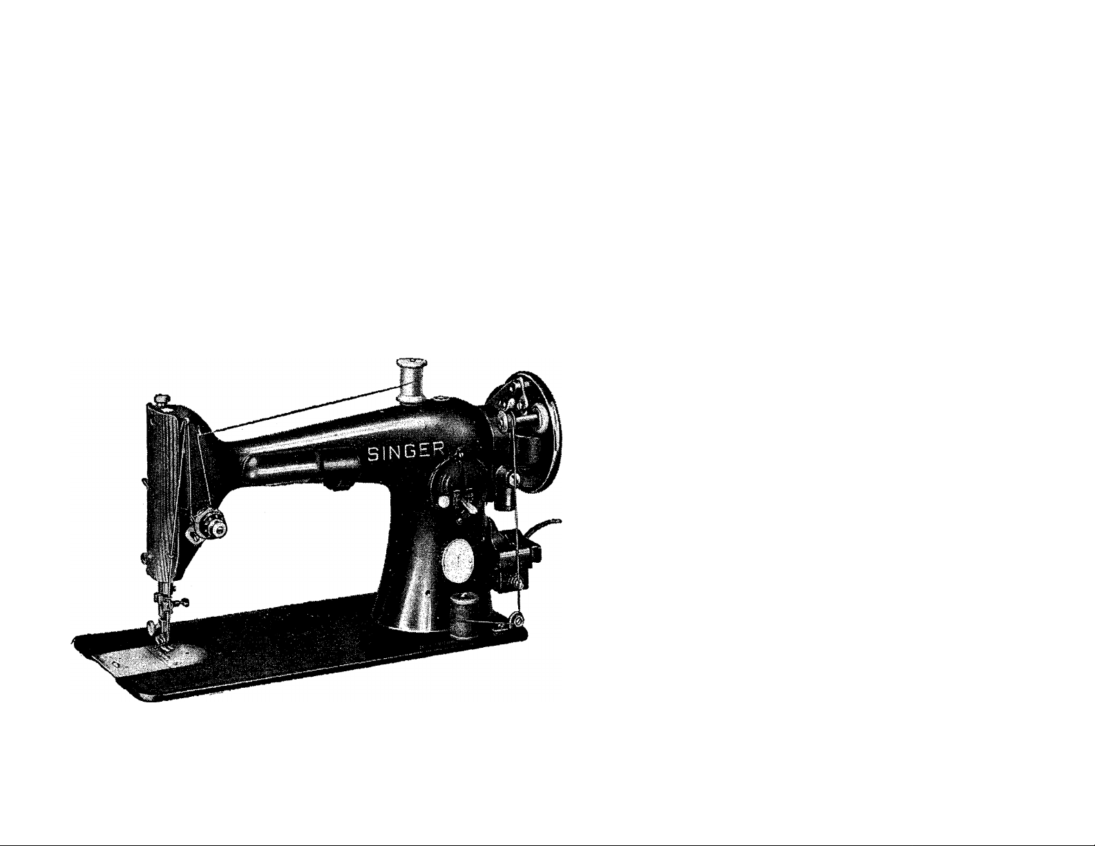
AS THE OWNER OF THIS SINGER 201
You own a machine with a tradition of superior crafts
manship—a tradition you will recognize in the
smooth, efficient operation of this motor-driven elec
tric sewing machine. Operating either forward or
backward, it forms a lock stitch.
The machine and the foot- or knee - operated
speed control are stored in any one of a variety of
versatile and attractive sewing machine cabinets with
extra room for sewing accessories.
Copyright © 1957 by The Singer Company
2
Page 4
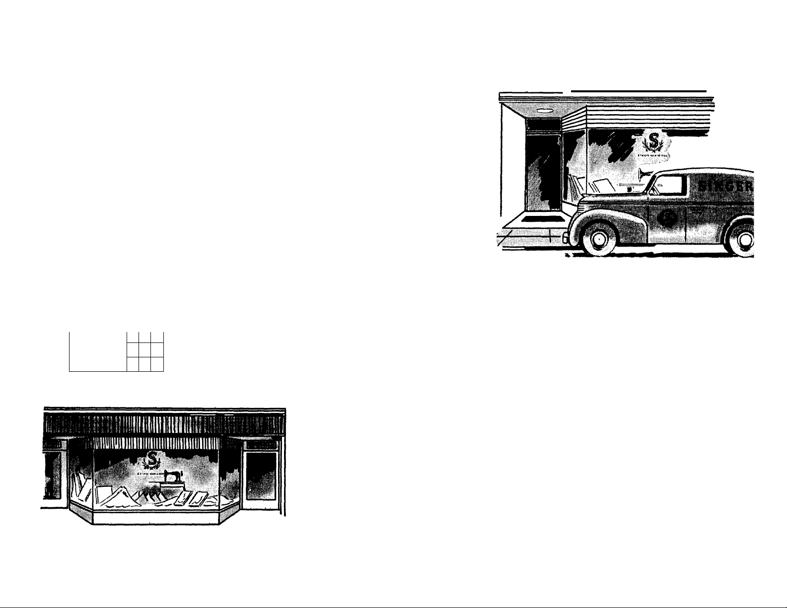
SINGER SERVICE
Wherever you go you will find expert, depend
able SINGER Service nearby. SINGER is inter
ested in helping you keep your SINGER
Sewing Machine in top condition. That’s why
it makes sense to call your SINGER Represen
tative if your machine ever requires attention.
He will submit a written estimate for your
approval. Look for the familiar red “S" on
your SINGER SEWING CENTER and the
handy SINGER Service Car.
EVERYTHING FOR THE WOMAN WHO SEWS
SINGER
' ^
SINGER
The answer to your sewing needs is at your SINGER
SEWING CENTER. There you will find a wide
choice of patterns, buttons and thread, as well as
Finishing Services such as covering buttons, hem
stitching, making belts and buckles, to mention a
few. Look in your telephone directory under
The Singer Company for the SINGER SEWING
CENTER nearest you.
3
Page 5
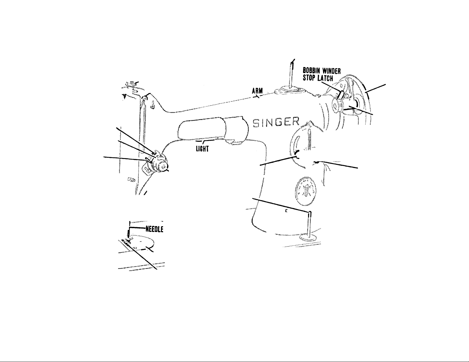
PRESSURE REGULATING
FACE PLATE SCREW^--^ ^
PRESSER BAR LIFTER J
SPOOL PIN
THUMB SCREW
HAND WHEEL
THREAD TAKE-UP
LEVER
FACE PUTE<
TENSION DISCS ^
TENSION INDICATOR DIAL
THREAD TAKE-UP
SPRING
THUMB SCREW>^^:
THREAD GUARD
THREAD CUHER
PRESSER BAR^-^,^
PRESSER FOOT
THUMB SCREW:ir>f|||
;PRESSER JO|r^f
BED SLIDE PUTE^'-
'TENSION REGULATING
THUMB NUT
NEEDLE BAR
NEEDLE CLAMP
THUMB SCREW
neeoIe clamp
THROAT PLATE
FEED DOB
STITCH REGULATOR
THUMB SCREW
BOBBIN WINDER
SPOOL PIN
BED
^1/ I i
y
,. STITCH REGULATOR
( X:'\f AND FEED
\ reversing HANDLE
I LIGHT TOGGLE SWITCH
BOBBIN WINDER
STITCH INDICATOR
----
PUTE
3-PIN TERMINAL BOOT
BOBBIN WINDER
THREAD TENSION
Fig. 2. Names of Principal Parts of Machine
4
Page 6

Motor
To Connect Machine to Electric Service Line
The SINGER* electric motor, located at
back of machine, is regularly furnished
for operation on a direct current of
110-120 volts or on alternating current
of 110-120 volts, 25 to 75 cycles. Special
motors can be furnished for direct or
alternating current for any voltage betvsreen 50 and 250, and for 32 volts direct
current.
CAUTION
When you have finished your sewing, always dis
Before connecting the machine to elec
tric service line, be sure that the voltage
and the number of cycles stamped on the
motor nameplate are within the range
marked on the electric meter installed
by the electric power company.
Push terminal plug into the three-pin
terminal block (see Fig. 2, page 4) at
the right of machine and connect plug at
other end of cord to an electric outlet.
connect plug from electric outlet.
5
Page 7
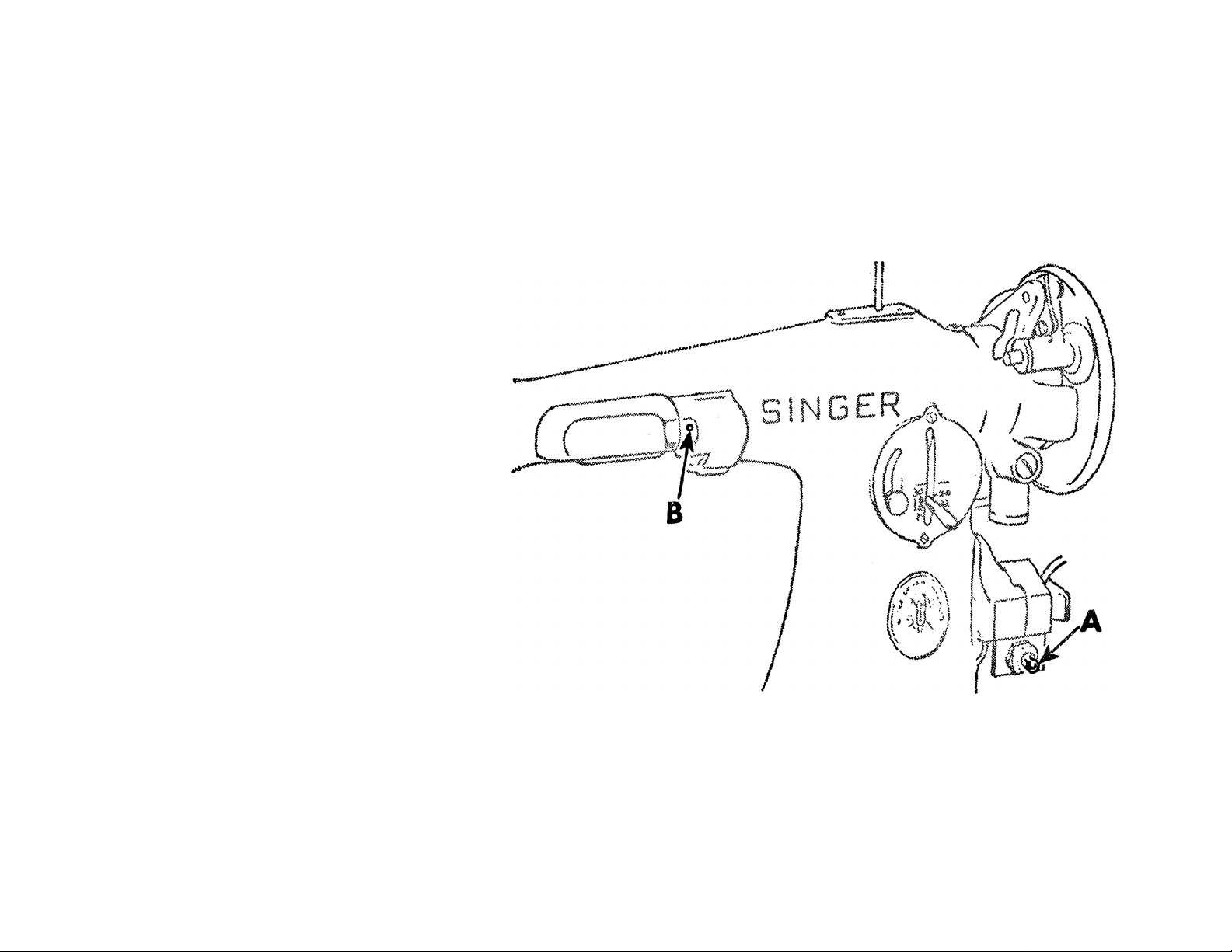
Turn Light “on” or “off”
A switch is conveniently lo
cated at front of three-pin
terminal block as shown at
A in Fi^. 3.
To
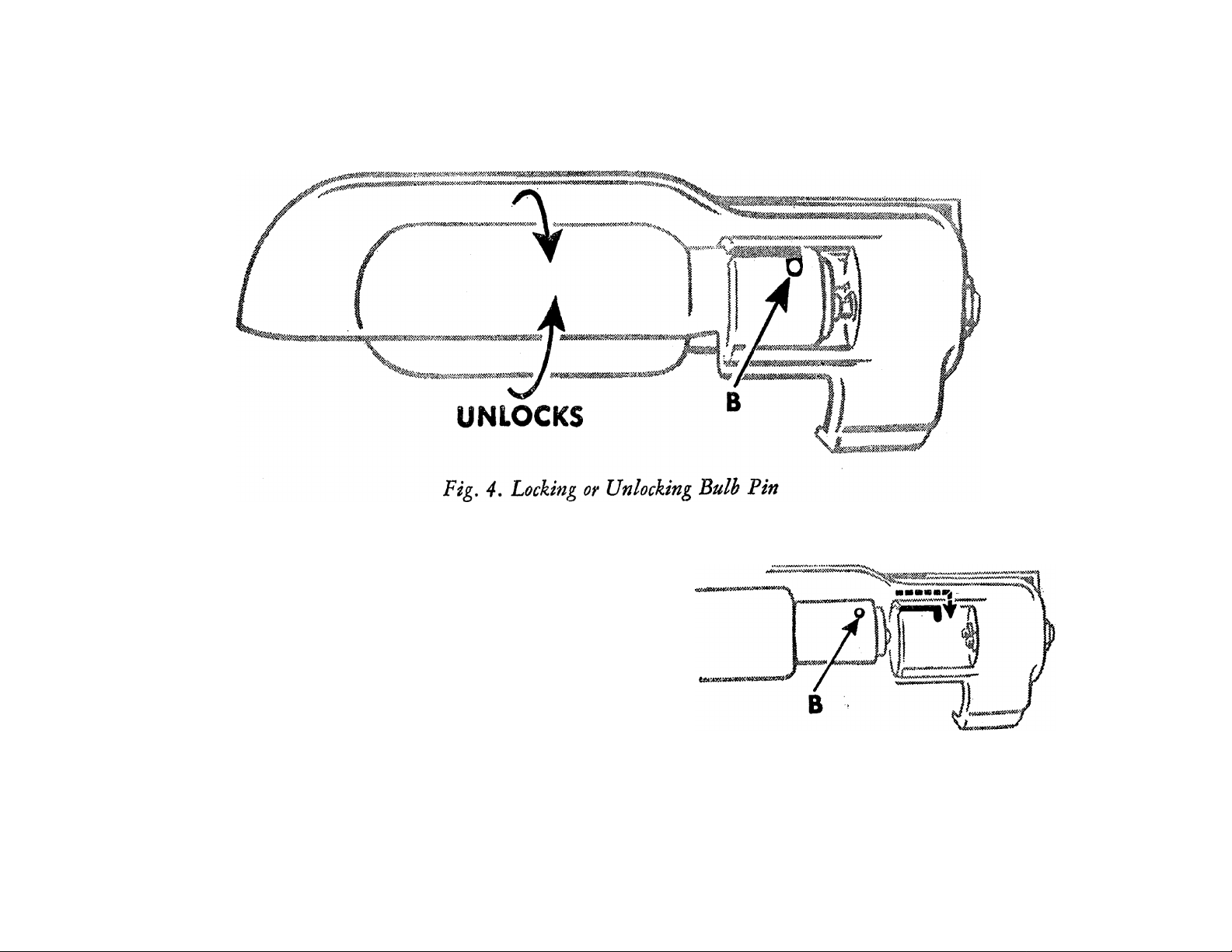
Remove the Bulb
Do not attempt to unscrew
the bulb. It is of the bayonet
and socket type and does not
unscrew. Press bulb into
light and at same time turn
bulb over toward machine
as far as it will go to unlock
bulb pin B as shown in
Fig. 4, Then withdraw bulb.
Fig. 3. Electric Light and Switch
6
Page 8
To lnsgrt a New Bulb
LOCKS
Insert a new bulb into light socket, as
shown in Fig. 5j and turn it over away
from machine, as shown in Kg. 4,
until bulb pin B enters the notch in
socket and locks into position.
Fig. 5. Inserting Bulb in Socket
7
Page 9
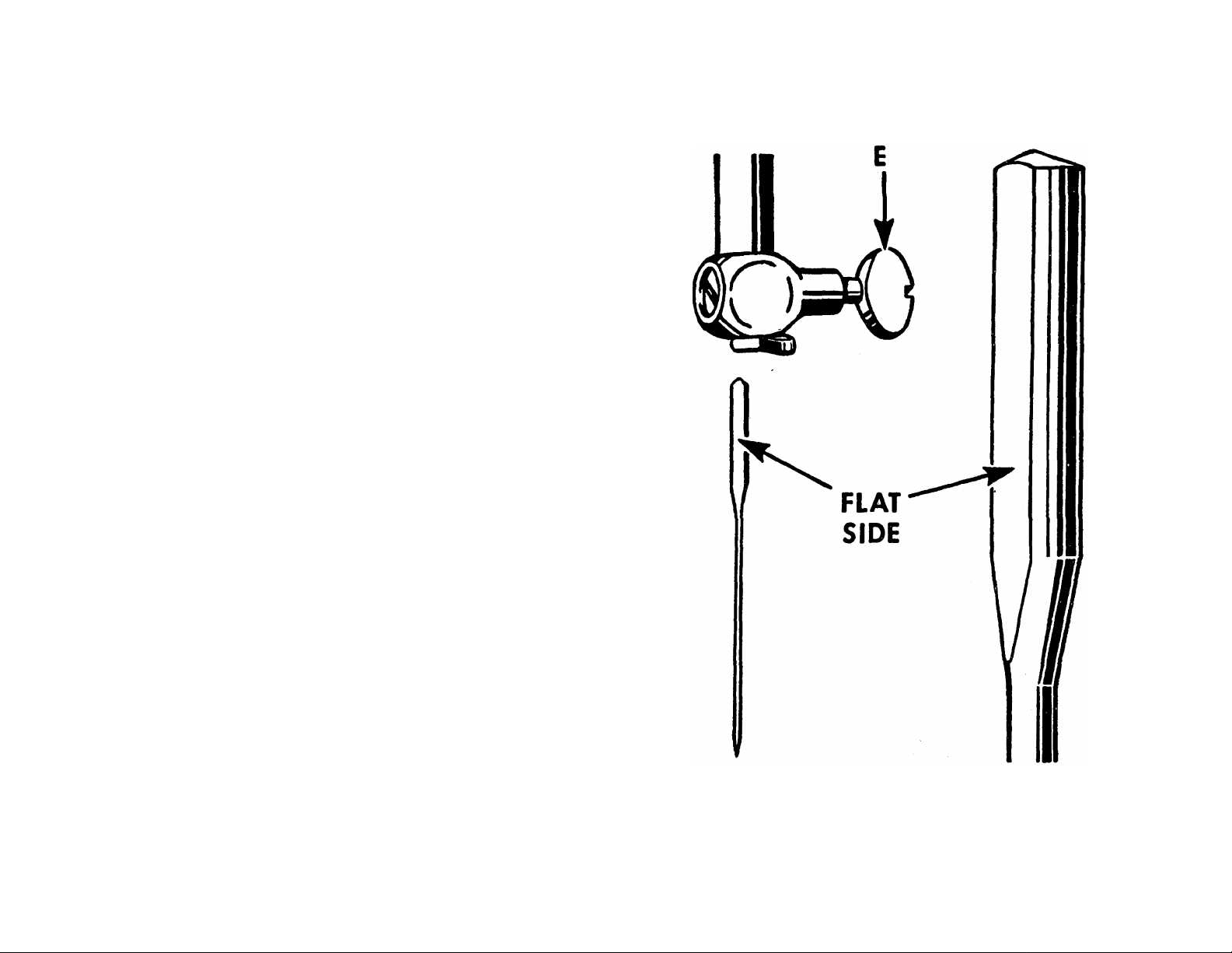
This machine uses a 15X1 Needle
—available in sizes 9, 11, 14, 16,
18, 19 and 21.
For perfect stitching, the thread should
be selected according to the fabric to be
stitched and the needle must be the
correct size for the thread which must
pass freely through eye of needle. Select
the correct needle according to the chart
on page 9. Be sure that needle is not
blunt or bent.
'■ '4;
Raise needle bar to its highest position
and loosen thumb screw E in needle
clamp. Insert needle, with its flat side
to the left, up into the needle clamp as
far as it will go, then tighten thumb
screw E.
Fig. 6. Setting the Needle
8
Page 10

CHART SHOWING THE RELATIONSHIP OF TYPES OF FABRICS, THREAD
AND NEEDLE SIZES AND MACHINE STITCH SETTINGS
TYPES OF FABRICS
Filmy materials comparable to net, marquisette,
chifFon, silk, organdy, ninon, silk velvet, nylon
sheers.
Sheer materials comparable to lawn, dimity, voile,
batiste, rayon sheer, rayon crepe, silk crepe.
Lightweight materials comparable to gingham,
chambray, sheer wool crepe, taffeta.
Medium lightweight materials comparable to
poplin, pique, percale, chintz, faille, bengaline,
wool flannel, wool crepe, wool jersey.
Medium heavy materials comparable to crash,
gabardine, rep, corduroy, velveteen.
Heavy materials comparable to sailcloth, sturdy
denim, ticking, drill cloth.
THREAD SIZES
100 Cotton
00 and 000 Silk
80 to 100 Cotton
0 Silk
50 Mercerized
60 to 80 Cotton
A or B Silk
50 Mercerized
50 to 70 Cotton
B Silk
50 Mercerized
40 to 50 Cotton
C Silk
Heavy Duty Merc.
30 to 40 Cotton
24 to 30 Cotton
D Silk
NEEDLE
SIZES
9
11
14
14
16
18 or 19
18
19
18 or 19
MACHINE STITCH SETTINGS
Inside Seams
20
16
12 18
12
10 12
8
Top Stitching
30
20
16
10
40 to 60 Linen
Very heavy materials comparable to overcoating.
Plastic materials. Mercerized Cotton
20 to 24 Cotton
E Silk
21
11
When ordering needles, always specify "Class and Variety 15 x 1” and state the size and quantity required.
You will obtain the best stitching results from your Sewing Machine if it is fitted with a SINGER* Needle.
9
6 8
10 12
Page 11
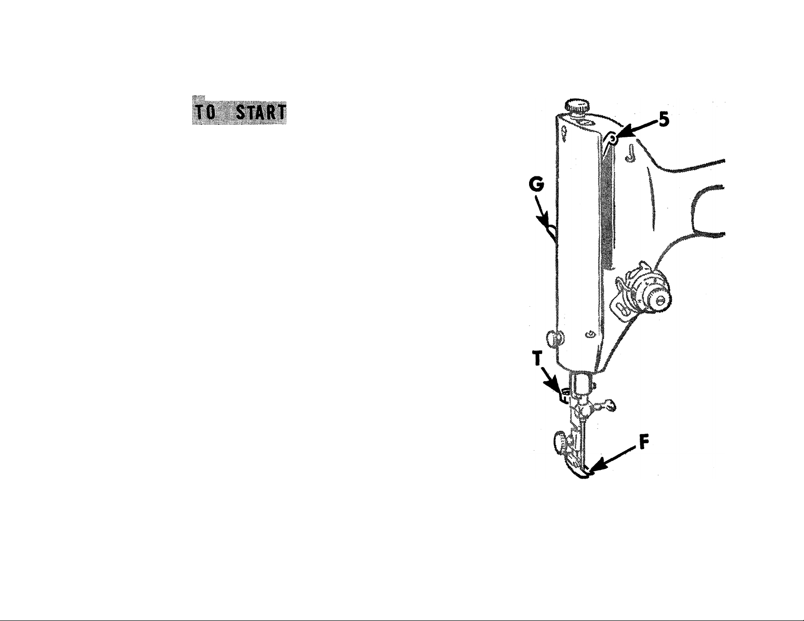
Raise presser foot F by means of presser bar lifter
G to prevent injury to the foot F and feed
Place a piece of cloth under presser foot and let
the foot down upon it.
Turn on electric current and, if the combination
knee and foot controller is installed as a knee
1
controller, press coritroller to the right,, or, if
controller is placed on the floor to be used as a
foot controller, pre?s down on pedal of con
troller. As the pressure on controller is increased,
the speed of machine is increased, the speed being
controlled entirely by amount of pressure on con
troller. Operate machine in this way, without
being threaded, until you have become accus
tomed to guiding the material and operating the
controller.
Si,,..... ,
Fig. 7. Front View of Machine
10
Page 12
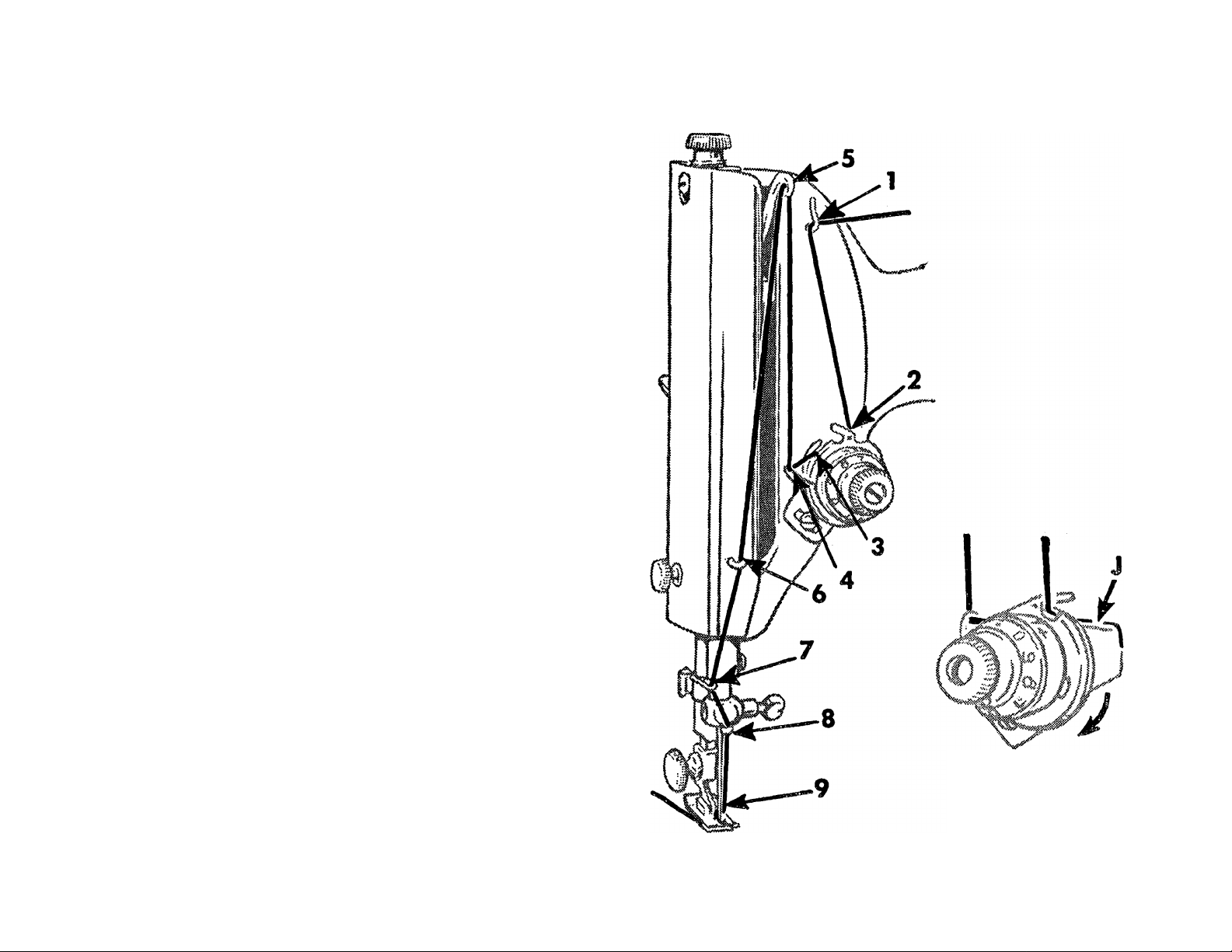
Raise take-up lever 5 to its highest point.
Place spool of thread on spool pin at top of
machine
Pass thread through thread guide 1
Down, under and from right to left be
tween tension discs 2 (thread guard J,
Fig. 9 guiding thread between discs).
Hold spool tightly and pull thread against
take-up spring 4 until it enters retaining
fork 3
Pass thread from right to left through
hole 5 in take-up lever
Down through guide 6 on face plate
Into guide 7 on needle bar bushing
Into guide 8 on needle clamp
From right to left through eye 9 of needle.
Draw about two inches of thread through
eye of needle with which to start sewing.
Fig. 8. Upper Threading
Fig. 9. Threading
Tension Discs
11
Page 13
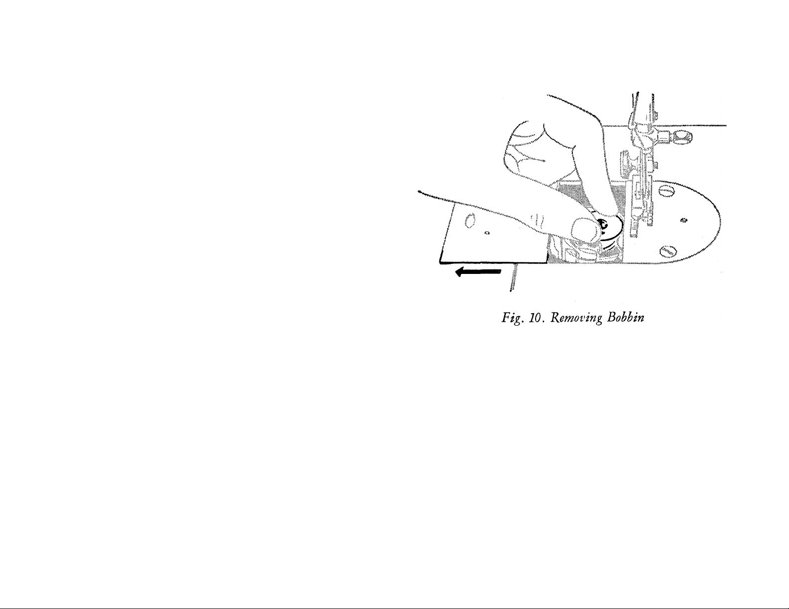
Ttf IWaVfi Tlii
Raise take-up lever 5, Fig. 8 to its
highest point. Draw the bed slide
toward the left, in the bed of machine.
Lift out bobbin with thumb and fore
finger of left hand as shown in Fig. 10.
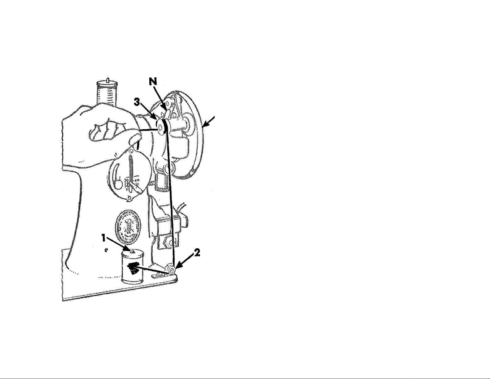
See Fig. 11
1. Place bobbin on spindle with pin of
spindle entering slot in right side of
bobbin.
2. Lock bobbin in place bv pressing
bobbin winder down until latch N,
Fig. 11 engages.
3- Hold hand wheel L and loosen large
knurled screw on hand wheel by turning
it over toward you.
4. Place spool of thread on spool pin 1.
Draw thread under and between tension
discs 2. Lead thread up through hole in
bobbin 3 from the inside.
5. Hold end of thread as shown in
Fig. 11 and press controller as for sew
ing. Continue to hold end of thread
until it breaks off.
12
Page 14
Allow tension discs to control flow of
thread. Do not guide or hold thread
when winding bobbin.
The bobbin winder will stop automati
cally when the bobbin is filled.
Remove bobbin from spindle and tighten
the large knurled screw on the hand
wheel L.
If pressure of bobbin winder pulley
Fig. 11. Winding the Bobbin
against hub of hand wheel is insufficient
for winding the bobbin, press down
bobbin winder until latch N, Figs. 11
and 12 drops and holds it in position.
13
Page 15
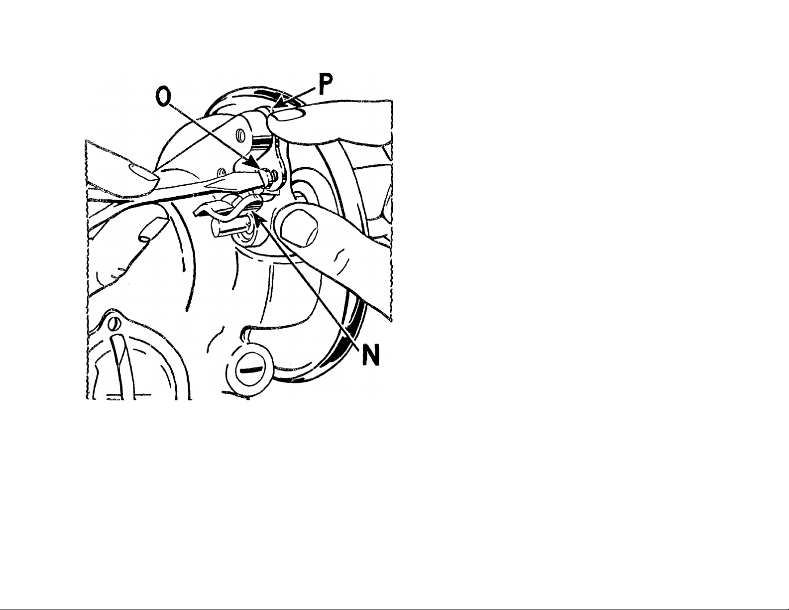
screw 0. If thread does not wind
evenly on bobbin, loosen screw which
holds tension bracket 2, Fig. 11 in
position.
Move bracket to the left if bobbin winds
high on right; move bracket to the right
if bobbin winds high on left. When
bracket is properly centered, thread will
wind evenly across bobbin.
Bobbins can be wound while machine is
sewing, by following instructions on
page 12, omitting item 3-
TO REPLACE THE BOBBIN AND
THREAD THE BOBBIN CASE
Fig. 12. Adjustment of Bobhm Winder
Loosen adjusting screw 0, Fig. 12.
With forefinger, push back upper end of
slotted plate P as far as it will go,
as shown in Fig. 12, and at the same
time, press bobbin winder pulley against
hub of hand wheel. Tighten adjusting
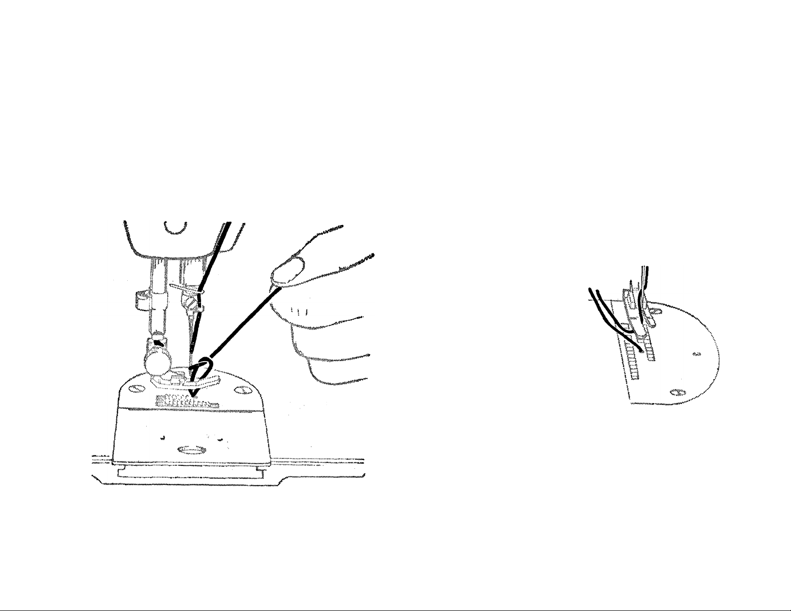
Hold bobbin between thumb and fore
finger of left hand; thread drawing from
right to left, as shown in Fig. 13.
Place bobbin in bobbin case. Draw
thread into slot 1, Fig. 14 in bobbin
case, as shown in Fig. 14.
Draw thread toward front between bob
bin case and tension spring until it
passes notch 2, Fig. 15 in bobbin case,
as shown in Fig. 15. Close slide and at
14
Page 16
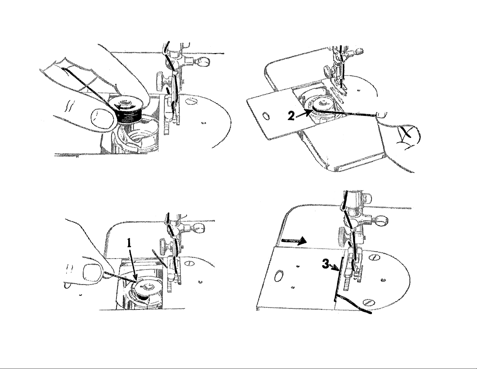
Fig. 13. Replacing Bobbin
i» / —’
if
c w w •'■ v.v. *'■ '■ •’
same time draw thread into long notch
in right edge of slide, as shown at 3,
Fig. 16.
4*f
Fig. 14. Threading Bobbin Case
Fig. 15. Bobbin Case Threaded
Fig. 16. Under Threading Completed
15
Page 17
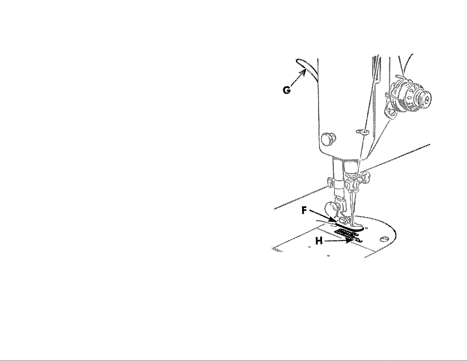
until needle goes down and up again
and thread take-up lever 5, Fig. 1 9 is
Hold end of needle thread with left hand
and turn hand wheel over toward you
at its highest point. Pull up needle
thread and bobbin thread will come
with it, as shown in Fig. 17.
Lay both threads
back under presser
foot diagonally
across the feed, as
shown in Fig. 18, to
the right or left, de
pending upon which
side of needle the
Fig. 18
material is to be lo
Fig. 17. Drawing Up Bobbin Thread
cated, so that when presser foot is low
ered, threads will be firmly held between
the feed and the presser foot.
16
Page 18
t,,, .. --s.(
■; .v%wi«v*w ^ .
■ "'I
1. Bring take-up lever 5 to its highest position.
2. Place material under presser foot F.
3. Position needle in material.
4. Lower presser foot and start to sew.
NOTE:
Most materials require only guiding for best sewing
results. However, the miracle fabrics such as nylons,
synthetic fabrics, blends with various rayons, puffed
weaves, sheers, jerseys and tricots, which, by their
nature, require light pressure, also require support in
the form of holding the material taut at the back and
front of the needle as the needle enters the fabric. This
support assures a smooth, even seam. Never ptill the
material along when stitching.
Never operate the machine without cloth under pres
ser foot.
The slide over the bobbin case should be kept closed
when the machine is in operation.
The hand wheel must always turn over toward the
operator.
17
Fig. 19
Page 19

The numerals on the stitch indicator
plate V denote the approximate num~
her of stitches per inch.
To change length of stitch, loosen
thumb screw X and move it to bottom
of slot. Move stitch regulating lever W
until its upper side is in line with the
number of the desired length of stitch.
Move thumb screw X until stitch regu
lating plate (inside) touches lever W.
Tighten thumb screw X.
The machine will then make the indi
cated number of stitches to the inch in
either a forward direction (lever W at
lowest position) or a reverse direction
(lever W at highest position).
Fig. 20
Stop machine with thread take-up lever
5, Fig. 19 at its highest position. Raise
presser foot, draw the fabric back and
to the left, and sever the threads on
thread cutter T, Fig. 19* Place ends of
threads under presser foot, as shown in
Figo 18,
18
Page 20

§■
.
"y.
i-:
The longest stitch, No. 6 on the stitch
regulator, adjusted by leverW, Fig. 2 0,
is found satisfactory for basting. These
basting stitches can be easily removed
by clipping every sixth stitch and with
drawing the long, continuous thread.
Machine basting is firmer, more even
and much quicker than hand basting.
To feed the material from you, push
down stitch regulator lever W, Fig. 2 0
Stop machine when needle is in material.
Raise presser foot, turn work as desired,
lower the presser foot and resume sewing.
r'c ■ V'? '■ -'X ‘:
Use a shorter stitch when sewing bias
or curved seams to increase the elas
ticity of the seam and to prevent seami
failure under strain. No change in ten
sions is required.
PWMf: FEE
» s,' V.,
The direction of feed can be reversed at
any point of a seam without removing
to the numeral of stitch desired.
To feed the material toward you, raise
stitch regulator to the point where it
will make the desired length of stitch.
work from machine.
The reverse feed makes it easy to “back
stitch” and to fasten ends of seams.
19
Page 21
PRESSURE ON
M.edium
20
Page 22
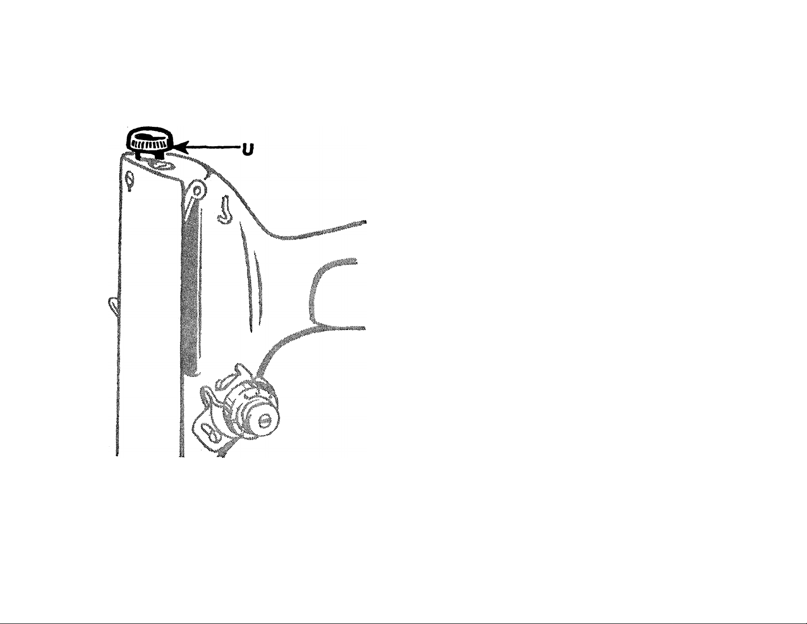
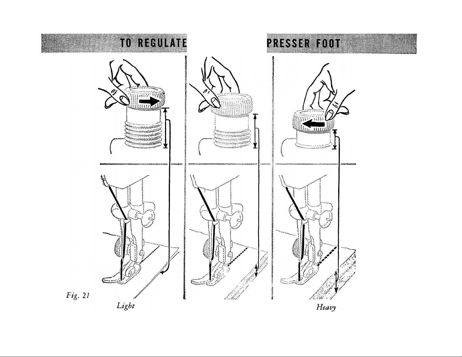
The amount of pressure influences the
ease with which you achieve a straight
seam and uniform stitching. The pres
sure should be heavy enough to prevent
side creepage of material and light
enough to carry the material without
marking.
To set a light pressure, turn thumb
screw U, Fig. 2 2 upward until fabric
moves easily under presser foot without
slipping and without showing feed
marks.
Fig. 22. Thumb Screto
for Adjusting Pressure
To set a heavy pressure, turn thumb
screw U downward until the fabric
moves easily and the seam edges are car
ried evenly by the foot and the feed.
21
Page 23
L^ViV'l-^WX' ''''' \
m. mm-W Mmm>
' ' ' 1 ' "i. ' ^<i.'*%'i'Kvjw^^i'ii' ""-S-V i i\Xv'^v>l^^ 'i 'v'. ■i'S
^’1* ^ ^,\-=-^''''\
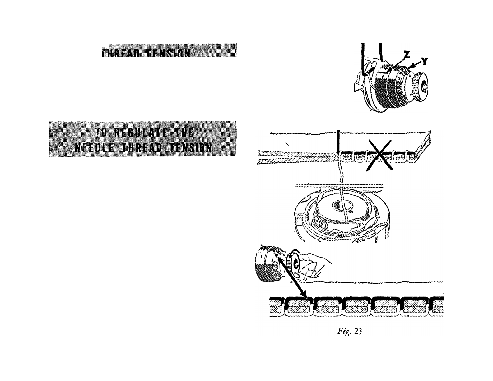
For perfect stitching, the tension on
needle and bobbin threads must be
heavy enough to pull threads to center
of material to mate a firm stitch.
NOTE: Unless the bobbin thread ten
sion has been altered, a wide range of
threads, from fine silk to heavy cottons,
can be formed into a perfect stitch by
regulating the needle thread tension
only«
The tension on needle thread can be
tested only when presser foot is down.
The numerals “0” to “9” on dial Y
indicate different degrees of tension that
can be obtained. The higher the number
the greater the tension. The numbers do
not denote size of thread or ounces of
tension.
22
Page 24

When tension has been correctly set for
average sewing, note number at indi
cator line Z. This setting may be
quickly regained should the tension be
altered for special work or a change in
size of thread.
In the unbalanced tensions shown at top
of Fig. 2 3 caused by too heavy tension
on needle thread, the needle thread lies
straight along top side of material.
In the unbalanced tensions shown at
top of Fig. 24, caused by too light ten
sion bn needle thread, the bobbin
thread lies straight along under side of
material.
If perfect stitching cannot be obtained
by regulating the needle thread tension,
check for minimum tension at “0”
position and if necessary adjust as in
structed on page 2 7. Then regulate
bobbin thread tension as instructed on
pages 24 and 2 5.
Fig. 24
23
Page 25

iiiciSi¿i5lí«jt^^'^»elx^S;»NS^¿i¿x^»»i««i»«Al«ií^;ííW:i&^;^к>4«№^'»:4:&^^
Set needle thread tension at **4**, as
shown in Figs. 2 5 and 26.
The tension on bobbin thread is regu
lated by the screw of the tension spring,
as shown in Fig. 2 5.
Fig, 25. Adjustment Kequired When
Bobbin Tension is too Loose
When adjusting bobbin tension, a
slight turn of the screw is all that is
needed to make a fine adjustment.
24
Page 26

To increase tension, turn screw gradu
ally over to the right.
Fig. 26. Adjustment Required When
Bobbin Tension is too Tight
To decrease tension, turn screw gradu
ally over to the left.
fTf
25
Page 27

Should it become necessary to remove
thumb nut. Then remove tension parts
and disassemble the tension, proceed as
follows:
Turn thumb nut A2, Fig. 2 7 over
toward the left until it stops at “0”
on numbered dial Y. Press in dial to dis
engage pin B2 in thumb nut and remove
4$- —
Fig. 27. Needle Thread Tension Disassembled
from stud J2 as shown below. To
remove pin H2 from stud J2, remove
face plate from machine and tilt ma
chine so that the pin will drop out. Do
not remove stud J2. (It is shown re
moved in Fig. 2 7, only for the purpose
of illustration.)
I
See Fig. 27 tension discs on stud, having the flat.
Replace face plate, insert tension re- thread-bearing sides of discs together,
leasing pin H2 in stud. Place the two Place thread guard plate K2 on stud,
26
Page 28

being sure that extension M 2 enters the
“0”. Thread the tension with size 50
hole provided for it in the arm of the
machine to prevent plate from turning
on stud.
Next, replace indicator Z with the
large open side facing end of stud (out
ward) so that the plus and minus signs
can be readily seen from a sewing
position. Insert tension spring D2 in
indicator so that first half turn E2 of
this spring will straddle lower half of
tension stud. Guide stop washer C2
onto stud so that extension N2 will be
above tension stud as shown in Fig. 2 7.
Next place numbered dial on stud so
that numeral 2 is opposite stop washer
mercerized cotton and pull thread
through tension discs to test amount
of tension at “0” position. At this
point there should be a barely percepti
ble pull on thread to indicate that there
is a minim.um tension, which will grad
ually increase with the turn of thumb
nut to right, providing a full range of
tensions from light to heavy within one
revolution of thumb nut. If pull is too
strong for a minimum tension, press in
numbered dial Y, to disengage pin B2
in thumb nut from dial and reset pin in
one of holes to left of previous setting.
This resetting of pin will produce less
extension N2, then push dial to com
press spring so that thumb nut can be
turned onto'stud, carefully guiding pin
in thumb nut into one of holes in num
bered dial. Lower presser bar and turn
thumb nut A2 to left until it stops at
tension at zero. On the other hand,
should there be insufficient tension at
zero, press in dial Yand reset pin B2 in
one or holes to right of previous setting.
Repeat this process until the desired
minimum tension is obtainedc
27
Page 29

ilwi
.^ :;?" '’v'o .. v.";.— ^"
. ^ ^ .c - ' \ ^ ' _ ' T'L 'J: -
^'- . \ '■ ■ ' ;V ' CCI
>»i>>VC^'Î%ÎVXwftiiX«!K'»X^%vMÎiisÎîASiriÎ^!i^TO
; ' *■■■ ' ■
Breaking of needles might be caused
by:
1. Incorrect size of needle for thread and
material. See page 9.
2. Needle bent.
3. Pulling of material when stitching.
4. Needle striking improperly fastened
presser foot or attachments.
5. Crossing thick seams with too small
a needle.
Breaking of needle thread might be
caused by:
1. A knot in the thread.
4. Needle set incorrectly. See page 8.
5. Needle blunt or bent.
6. Thread too coarse for needle. See
page 9.
7. Roughened hole in throat plate.
8. Incorrect arrangement of threads to
start sewing. See page 16.
9. Damaged sewing hook.
Breaking of bobbin thread might be
caused by:
1. Incorrect threading of the bobbin
case. See page 15.
2. Bobbin thread tension too tight. See
pages 24 and 2 5.
2. Incorrect threading. See page 11.
3. Upper tension too tight. See pages
22 and 2 3.
3. Bobbin wound unevenly. See page
14.
4. Damaged bobbin.
28
Page 30

Skipping of stitches might be caused
NOTE: If machine runs heavily after
by;
1. Incorrect setting of needle. See
page 8.
2. Needle blunt or bent.
3. Needle too small for thread. See
page 9.
4. Needle rubbing presser foot.
Gathering or Puckering of material
might be caused by:
1. Failure to use crisp lawn or organdy
backing when stitching on sheer
materials.
2. Excessive needle and bobbin thread
tensions.
standing idle for a long period, apply
a few drops of kerosene at all oil
ing points, run the machine for a few
minutes, then wipe clean and apply
SINGER* Oil as described on pages
33 to 37.
SINGER Needles should be used
in SINGER Machines.
These Needles and their Containers
are marked with the
Company’s Trade Mark“ SINGER ”1
Needles in Containers marked
“FOR SINGER MACHINES”
are NOT SINGER made Needles.
29
Page 31

' ^ \ a' '■■.'i > j’'
;. DARNIMfi
!. V '*c i;.'o'. ^ %i ^^■ ; „
Turn machine back on its hinges. Un
screw the thumb screw P2, Fig. 2 8
out of the lower hole A in the crank
Q2 until the crank Q2 is released.
Move feed lifting crank Q2 downward
so that thumb screw P2 will enter
upper hole B. Insert thumb screw P2
in this hole and tighten firmly. The
feed is thus rendered inoperative and
will not interfere with the free move
ment of the work. Bring machine for
ward into place.
Move stitch regulating lever W, Fig.
2 0, page 1 8 to its neutral position in
the center of slot at front of machine.
Remove presser foot and let down
presser bar lifter G, Fig. 19, page 17
to restore tension on needle thread
which is released when lifter is raised.
Draw up bobbin thread as instructed on
page 16.
30
Page 32

Darning:
When darning flat work, it is advisable
to use embroidery hoops to hold the
work. Place the work in machine, hav
ing the unworn part near the hole
\ under the needle. Start darning by mak
ing a line of stitches across the hole a
little longer than width of hole. Con
tinue making parallel lines of stitches
Fig. 29 Starting the Darn
across hole, moving the work backward
and forward, as shown in Fig. 2 9, and
at same time gradually moving the
work sidewise until hole is covered with
/
lines of stitches running across hole.
Then turn the work 90°, as shown in
'/V"
I
^ , Fig. 30 and continue as before moving
i'A work backward and forward, form
"'V?.
ing parallel lines of stitches until the
Av,
i
vV
i.,.„A
first group of stitches across hole are
completely covered and the darn is
finished.
When you have finished darning, raise
Fig. 30. Darning in Process
presser bar lifter and replace presser
31
Page 33

foot. Turn machine back on its hinges
and turn thumb screw P2, Fig. 28,
page 30 out of upper hole B, Fig. 28
Embroidering:
Prepare the machine the same as for
darning as instructed on page 30, with
in feed lifting crank Q2, Fig. 28, and
into lower hole A, Fig. 28. Make sure
that thumb screw is firmly tightened.
Bring machine forward into place, re
turn stitch regulating lever W, Fig. 2 0,
page IS, to its original position and
the machine is ready for regular stitch
ing. Stockings and socks, underwear,
etc., can be more conveniently darned
on the machine with the SINGER*
DARNING and Embroidery Attach
the following exceptions—
For surface embroidery, remove the
presser foot to give a clear view of the
stitching in process.
For lace embroidery remove the regular
presser foot and replace with Foot
160858 or with Darning and Embroidery
Attachment 160720, either of which
can be purchased from any SINGER
SEWING CENTER or from any
SINGER Salesman. See instructions on
ment 160720 (page 68).
page 68.
32
Page 34

../-v: ;!&'■ 5Y, '-
.........
i;*
:;v.' >V'.- .':, -
WL tHt
If machine is used continuously, it
should be oiled daily. If moderately
used, an occasional oiling is sufficient.
Preparation: Remove face plate. Draw
bed slide plate to the left. Remove dust
and lint (see instructions on page 3 8).
Swing rear cover plate up toward hand
wheel.
Fig. 31. Front Views Showing Oiling Points
33
Page 35

Oiling: Apply a drop of oil to the
places indicated by unlettered arrows in
Figs. 31, 32,33 and 34, and 3 drops of
oil to the places so indicated in Figs. 31
and 34.
After applying one drop of oil to the
places indicated by the unlettered ar
rows in Fig. 32, replace face plate and
fasten it as before.
Fig. 32. End View Showing Oiling Pointi
34
Page 36

To reach parts uridenieath
bed of machine, turn ma
chine back on its hinges.
Apply one drop of oil to the
places indicated by the un
lettered arrows in Fig. 33.
The gears concealed by gear cover E2, Fig’» 3 3 aic
D2 oiled through oil hole E, Fig. 31.
The gears concealed by gear cover D, Fig. 3 3 are
Fig. 33. Views, Showing Oiling Points in
Base of Niachine
oiled through the space just above this cover, as
indicated by arrow D2. After oiling the gears at
D2 , rotate the hand wheel toward you to distribute
the oil on these gears.
35
Page 37

Turn hand wheel over toward you until
connecting rod R2, Fig. 34 is at its
highest position. Then apply oil through
hole in top of machine to the wick
which is retained in cap of connecting
rod, as shown in Fig. 34. Also oil the
other moving parts inside and replace
cover.
Machine Working Heavily
If the machine runs hard after standing
idle for some time, use a little kerosene
in the oiling places, run the machine
rapidly, then wipe clean and oil.
36
Fig. 34. Oiling Foints At the Back
of the M.achine
Page 38

:
NEVER USE OIL OR ORDINARY
GREASE FOR LUBRICATING
MOTOR. USE the SINGER* Motor
Lubricant, supplied with the machine.
Machine is shipped from factory with
sufficient SINGER Motor Lubricant
in motor grease cups T2, Fig. 35, for
approximately one year’s use.
At least once a year thereafter, turn
machine back on its hinges and remove
the two thumb screws from the two
grease cups T2. Clean out interior of
cups. Insert tip of motor lubricant tube
into each grease cup as shown in
Fig. 35, and while holding tube firmly
against bottom of grease cup squeeze
enough grease into each cup to fill it.
Replace and tighten thumb screws.
37
Fig. 35. Lubricating the hAotor
Page 39

After considerable use, the stitch form
Occasionally remove the bobbin case
ing mechanism in bed of machine may
become clogged with lint and this may
interfere with the perfect operation of
the machine.
from machine, as instructed below, and
remove any lint, etc., which has accu
mulated in machine.
Draw bed slide plate to the left. Turn
hand wheel over toward you until
^ needle is at its highest point and end of
the hook ring E is toward the front of
the machine, as shown in Fig. 36.
Insert the blade of small tension screw
driver 120378, which is furnished with
the machine, into slot C between the
ring and the edge of the spring, as
Fig, 36. View from Left Endy Showing Position of Bobbin
Case and Hook Ring for Removal from Machine
shown in Fig. 36. With a downward
pressure, turn the screwdriver one-half
turn to the right so that the screwdriver
will drop into the slot and unlock the
spring. With the right hand, hold the
hand wheel to prevent its turning, and,
with the left, place the screwdriver
38
Page 40

against the edge of the slot in the ring
circular cutout B is opposite the spring
and push it around in the direction op
posite to the hook rotation until the
When replacing the parts,
first place the bobbin case [
into position with the finger
A, Fig. 37 in the opening in
the position plate under the
throat plate as shown in
Fig. 37. Turn the bobbin
case back and forth slightly
to make sure that it is proper
ly seated, then place the hook
D, as shown in Fig. 37. The ring E and
bobbin case may then be lifted out.
THROAT PLATE
ring E in position with the
cutout B opposite the spring
D. Press the ring into place
and turn it in the direction
of hook rotation until the
spring locks it in position.
Then replace the bobbin.
Fig. 37. View from Left End, Showing
Keflacement of Bobbin Case
39
Page 41

mitw
ATTACHMENTS
40
Page 42

The foot hemmer may
2. Lay about three inches of needle and
be used for hemming
edge of material, mak
ing hemmed and felled
seams and for hemming
and sewing on lace in
one operation.
Raise needle to its high
est point, remove pres
Fig. 38
Foot Hemmer
ser foot and attach foot
hemmer to presser bar
in place of presser foot.
Pull up bobbin thread as instructed on
page 16.
To Start Hem at Very Edge
bobbin threads back under hemmer.
Place creased edge of material under
hemmer with end of hem directly
under needle. Lower hemmer and
tack end of hem with two machine
stitches.
1. Fold edge of material twice, about
^ inch each time, for a distance of
about two inches. Crease folds.
41
Fig, 39. Starting Hem at Very End of Material
Page 43

3. Raise hemmer. Pull threads and hem
4. Lower hemmer and start to sew,
slightly from you with left hand,
then while holding threads, draw
material toward you, with right hand,
into scroll of hemmer until tacked
end is caught in hemmer, as shown in
Fig. 39.
slightly pulling threads back while
sewing. Keep mouth of hemmer
full to produce a smooth, even
hem as shown in Fig. 40.
To Make a Hemmed Seam with Foot Hemmer
Fig. 40. Hemming Edge of Material and
Fulling Back Threads While Sewing
Fig. 41. Making a
Hemmed Seam
(First Operation')
1. When making this seam, the gar
ment must first be fitted and the edge
42
Page 44

of material trimmed, allowing for
2. The free edge of hemmed seam may
about 3^ inch of seam. Insert the two
edges of material, right sides to
gether, in the hemmer in same man
ner as a single hem as shown in
Fig. 41. If the material is bulky,
place edge of upper piece of material
about inch left of edge of under
piece.
be stitched flat to garment, if de
sired. To do this, open the work out
flat, wrong side up, then insert the
hem in scroll of hemmer, holding
edge of hem in position while it is
being stitched. If seam is stitched
flat to garment, one row of stitching
is visible on the right side.
To Make a Felled Seam
with Foot Hemmer
1. Place right sides of material together,
having edge of upper piece about 3^
Fig, 41. Making a
Hemmed Seam
(^Second Operation^
43
inch to the left of edge of under
piece. Stitch the two pieces together,
using hemmer as a presser foot.
Guide both pieces by the projecting
toe of hemmer, as shown in Fig. 43.
Page 45

2. Open the work out flat, wrong side
3. Raise presser bar and insert edge of
up, and hem free edge of seam,
stitching it flat to garment as shown
in Fig. 44.
Fi£. 43. lAaking a
Felled Seam
(First Operation)
Fig. 44. Making a
Felled Seam
(Second Operation)
lace in slot of hemmer and back
under hemmer.
4. Lower presser bar and start sewing,
catching edge of lace with needle.
5. Guide hem with right hand and lace
with left hand, being careful not to
stretch lace as it enters hemmer.
To Hem and Sew on Lace
in One Operation
1. Start hem in regular way.
2. Hold hem in position with needle.
Fig. 45. Hemming and Sewing on Lace
44
Page 46

■
' ■ > . .■■ i ■ 1 /■'. „ <•
To Make Hems
from 3/16 to 15/16 Inch Wide
1. Attach adjustable hemmer to presser
bar in place of presser foot.
2. Pull up bobbin thread, as instructed
on page 16.
3. Loosen thumb screw on hemmer and
move scale until pointer registers
with number of desired width of
hem. (No. 1 indicates the narrowest
hem and No. 8, the widest.) Then
tighten thumb screw.
4. Place cloth in hemmer and draw it
6. Guide sufficient cloth into hemmer to
turn hem properly.
back and forth until hem is formed,
as shown in Fig. 46.
5. Draw end of hem back under needle,
lower presser bar and start to sew.
45
Fig 46. Mutking Hem Up to Inch Wide
With Adjustable Hemmer
Page 47

The two upright guide pins, shown in
Fig. 47 eliminate manual guiding of
the binding.
This multi-slotted binder will apply
unfolded bias binding iS/fg inch in
width and commercial folded binding
in sizes 1, 2, 3, 4 and 5 to seams or to
edges of garments. These sizes of folded
binding are M, We and ]4 inch in
width, respectively, and are fed through
slots of corresponding sizes in the binder
scroll. See Fig. 47. Binding may be
purchased in a variety of materials and
colors.
For convenience in determining the
correct width of unfolded binding
(iWe inch), this measurement is marked
The wide range of bindings that can be
applied with this binder makes it useful
for a large variety of work. It will be
ADJUSTING
LUG
SCROLL FOR
OUTSIDE
t/,"
SLOTS FOR ^16
DIFFERENT
WIDTHS OF ^8
FOLDED Vie'
BINDING
CENTER SLOT
OF SCROLL
EDGE GUIDE
FOR PIPING
ONLY
UNFOLDED
BINDING
on the binder, as shown in Fig. 47.
f/g. 47. Mulpi-Slotfed Binder 160359
46
Page 48

found particularly advantageous for
making children’s wear, lingerie, sum
mer dresses, and other dainty articles
which call for narrower bindings.
As two different widths of binding of
contrasting colors can be fed through
binder at same time, attractive binding
and piping effects can be produced in
one operation.
Folded bias binding
must be inserted in the
slot or slots of corre
sponding sizes. See
Fig. 51.
Unfolded or raw edge
bias binding must be
inserted in the open
end of the scroll. See
Fig. 49 .
To Attach the Binder
Raise needle to its highest position.
Then attach binder to presser bar in
place of presser foot.
See that needle enters center of needle
hole.
To Insert Binding In Binder
Cut all binding to a long point to the
left, as shown in 48.
After inserting pointed
end of binding in bind
er, push it through until full width of
binding is under needle.
Guide binding by means of two upright
pins, as shown in Figs. 49 to 53.
To Insert Garment in Binder
Place edge to be bound as far to right as
it will go in center slot of scroll C2, as
shown in Fig. 4 9, and draw it back
under binder foot.
Fig. 48
47
Page 49

Lower binder by means of presser foot
to the right by means of lug B2 * Fig. 49.
lifter, and start to sew. Keep material
Fig. 49. Binding with Unfolded Binding
well within center slot of scroll so that
This is the usual adjustment when
binding straight edges.
When binding curves, move scroll to
left to bring inner edge of binding
farther from stitching and allow for
sweep of curve.
Piped Edge
To produce a piped edge on garments,
move lug B2, Fig. 50 to left to bring
edge will be caught in binding.
To Adjust the Binder
To bring inner edge of binding closer to
the stitching, move scroll C2, Fig. 49
Fig. 50. Position of Garment and Binding
When Piping Edges
48
Page 50

stitching about midway of folded
time. That is, if No. 1 is used, wider
binding.
Crease raw edges of garment toward
wrong side about H inch, and insert
folded edge, raw edges uppermost, into
edge guide on binder, and beneath
binding.
When stitched, both sides of garment
will be finished, and right side will
show piped edge.
Piping and Binding in One Operation
A garment can be piped and bound in
one operation, as shown in Fig. 51.
binding should not be smaller than No.
3. If No. 2 is used, wider binding
should not be less than No. 4. Never
use Nos. 1 and 2, or 2 and 3, etc.,
together.
Use the upright guide pins to guide the
wider of the two widths of binding, as
shown in Fig. 51.
IMPORTANT: When piping and
binding at same time, as shown in Fig.
51, insert narrow width of binding
first in its slot, then insert wider
width in its slot. Two consecutive
widths should not be used at same
49
Fig, 51. Piping and Finding in One Operation
Page 51

To Bind Outside Curves
If stitching does not catch edge of bind
Allow edge to be bound to pass freely
through scroll without crowding against
scroll wall. The material must be guided
from back of binder and to left, permit
ting unfinished edges to swing naturally
into scroll of binder.
Never pull binding while it is being fed
through binder, as this may stretch
binding, making it too narrow to stitch
or to turn in the edges.
When binding curves, turn material
only as fast as machine sews.
ing, adjust scroll slightly to the left.
To Bind Inside Curves
When binding an inside curve, straighten
out edge of material while feeding it
into binder, being careful not to stretch
material.
Do not push material in too fast as this
will pucker edge.
Do not stretch material as this will dis
tort edge so that curve will not have
proper shape when finished.
Fig. 52. Binding an Outside Curve
50
Page 52

Soft materials, like batiste or crepe de
For guidance in applying, rows of
chine, require a row of stitching added
close to edge of curve before binding.
To Apply French Folds to Curves
Place material under binder and stitch
binding onto face of material, as shown
in Fig. 53.
French folds, mark material with a line
of basting stitches or with chalk or
pencil.
This useful attachment is fastened to
machine in place of presser foot, and
will be found an
indispensable aid
whenever stitch
ing must be kept
accurately on ex
treme edge of a
Fig, 53. Applying a French Fold
piece of material.
The slots, num
■ ^4
bered from 1 to 5
Fig. 54
The Edge-Stitcher
51
Page 53

in Fig. 54, serve as guides for sewing
To Sew Lace Together
together laces, insertions and embroid
eries, sewing in position hemmed or
folded edges, piping or sewing flat
braid to a garment.
To Adjust the Edge-Stitcher
Fasten this attachment to presser bar in
place of presser foot.
Turn hand wheel slowly by hand to see
that needle goes through center of
needle hole.
The distance from line of stitching to
1. Insert one of the laces in slot 1 of
edge-stitcher and the other in slot
4, Fig. 54.
edge of material in slots is regulated by
moving lug D2, Fig. 54 to right or left.
If lug moves with difficulty, place a drop
of oil under blue spring, then wipe it
dry.
Fig. 55. Sewing Lace Together
52
Page 54

2. Adjust lug D2 until edges to be
2. Insert lace or ribbon in slot 4 of
joined are caught by the stitching.
3. Slightly overlap edges of lace while
stitching to keep them against ends
of slots.
4. Loosen both thread tensions to avoid
puckering of fine lace.
To Insert Lace or Ribbon
1. Fold edge of material to which lace
or ribbon is to be sewn and insert it
in slot 1, Fig. 54 of edge-stitcher.
edge-stitcher and proceed to sew.
3. Cut away surplus folded material
close to stitching.
To Pipe with Edge-Stitcher
1. Cut piping bias and twice width of
slot 3 so that it can be folded once.
2. Insert piping
with its
folded edge
to left in slot
3 and edge
to be piped
in slot 4,
Fig. 56. Setting in Lace Insertion
Fig. 54.
Fig. 57. Piping with
Edge-Stitcher
53
Page 55

To Apply Folded Bias Tape
To Stitch a Wide Hem
or Military Braid
1. Place garment under edge-stitcher
and tape in slot 1 or 4, Fig. 54.
2. To make square corners, sew to turn
ing point, remove tape from attach
ment, form corner by hand, replace
tape and continue stitching. See
Fig. 58.
3. To space two or more parallel rows,
mark material with a guide line,
using a crease, chalk or basting
thread.
1. A wide hem may be stitched evenly
on sheets, pillow slips, etc., with
edge-stitcher after hem has been
measured and edge turned.
2. Insert edge in slot 5, Fig. 54, and
adjust lug D2 to stitch as close to
edge as desired.
Fig. 59. Making a Wide Hem
Fig. 58. Applying Bias Folded Tape
54
Page 56

To Make a French Seam
To Tuck with Edge-Stitcher
1. To make a French seam of uniform
width, insert two edges to be joined,
wrong sides together, in slot 1 or 2,
Fig. 54, and stitch close to edge.
2. Fold both right sides together and in
sert back of seam in slot 1, as shown
in Fig. 60, and stitch, allowing just
enough margin to conceal raw edges.
The maximum width of tuck that can
be made with edge-stitcher is ^ inch.
1. Fold and crease material for desired
width of tuck.
Fig. 60. Making a French Seam
(Second Operation^
Fig. 61. Tucking with Edge-Stitcher
55
Page 57

2. For succeeding tucks, fold material
3. The fullness of shirring or amount of
the desired distance from previous
tuck, running the fold lengthwise
over a straight edge, then crease
folds.
3. Insert creased folds in slot 1, Fig. 54
and adjust edge-stitcher to right or
left for the desired width of tuck.
Use a light tension, short stitch and
fine thread and needle.
To Shirr with Gathering Foot
gathering is regulated by length of
stitch. A longer stitch increases full
ness of gathers.
1. Fasten gathering foot to presser bar
in place of presser foot.
2. Place material under gathering foot
and stitch in usual way.
Fig. 62. Shirring with Gathering Foot
56
Page 58

oil. Insert scrap of material in Rufiler
and operate attachment until no oil
appears on work.
Principal Parts
-V
^€/''-S" ,;-''v-.^» .^- \rM
Fig. 63. Principal Parts of Kuffler
Lubrication
At the beginning of each working day
lubricate Ruffler to insure smooth opera
A—Foot—attaches rufiler
to presser
bar.
B—Fork Arm—straddles needle clamp.
C—Adjusting Screw—regulates full
ness of gathers.
D—Projection—engages slots in ad
justing lever.
E—Adjusting Lever—sets rufiler to
gather or pleat once every 6 stitches
or once every 12 stitches or not at
all, as desired.
F—Adjusting Finger—regulates width
or size of pleats.
G—Separator Guide—edge of ma
terial placed in slots to keep head
ing of rufile even. Separates ruffling
material from material to which
tion and to prevent jamming, rust and
wear.
Apply one drop of oil at each point
indicated in Fig. 63. Wipe off excess
57
ruffle is being attached.
H—Ruffling Blade—pushes material;
forms pleats and pushes material
toward needle.
Page 59

J—Separator Blade—prevents ruffling
blade teeth from damaging material
or feed.
MATERIAL
1. Raise needle to its highest point.
2. Loosen presser foot thumb screw and
attach ruffler to presser bar in place
of presser foot, at same time placing
fork arm B astride needle clamp.
3- See that needle enters center of needle
hole in ruffler.
To Adjust Ruffler for Gathering
1. Swing adjusting finger F away from
needle.
2. Raise adjusting lever E and move it
until projection D can be entered in
Fig, 64. Correct Position for Material
to he Pjijfled
3. Insert material to be ruffled between
two blue blades Line 2, Fig. 64.
slot marked “1”.
Fig. 65. Gathering with Ruffler
58
Page 60

4. Draw material slightly back of nee
2, Place material to which ruffle is to
dle, lower presser bar and start to
sew.
5. For fine gathering, turn adjusting
screw C upward and shorten stitch.
6. For full gathering, turn adjusting
screw C downward and lengthen
stitch.
To Make a Ruffle and Sew It to a Garment In One Operation
1. Insert material to be ruffled between
two blue blades Line 2, Fig. 66.
be attached under separator blade
Line 1, Fig. 66.
3. Proceed same as for plain gathering.
To Make a Ruffle and Attach It With a Facing in One Operation
1. Insert material to be ruffled between
two blue blades Line 2, Fig. 68.
Fig. 66. Correct Positions for Materials
RUFFLING
MATERIAL^ 2
GARMENT-^
Fig. 67. Making a Ruffle and
Attaching It In One Operation
59
Page 61

2. Place material to which ruffle is to
be attached under separator blade
Line 1, Fig. 68.
3. Place facing material over upper blue
blade Line 4, Fig* 68.
Fig. 68. Correct Positions for lAaterials
4. It facing is to be on right side of .gar
ment, place wrong sides of garment
and ruffle together.
5. If facing is to be on wrong side, place
right sides of garment and ruffle
together.
To Pipe a Ruffle
1. Insert material to be ruffled between
two blue blades Line 3, Fig. 70.
60
Fig. 69. Making a Ruffle and Attaching
It With a Facing In One Operation
This material must not exceed 1 \i
inches in width.
IQI GARMENT;,^
RUFFLING ^
MATERIAL
Fig. 70, Correct Positions for Materials
Page 62

2. Piping material is usually cut on the
and insert it in rufiler, following
bias and it should be about 3^ inch
wide when folded in center. Place
piping material in rufiler, following
Line 5, Fig. 70 with folded edge of
piping to the right.
3. Fold edge of material to which pip
ing and ruffling are to be attached
Line 6, Fig. 70.
To Adjust Ruffler for Pleating
1. Raise adjusting lever E and move it
until projection D can be entered in
slot marked “6”. The rufiler will
then pleat once every six stitches. To
pleat once every 12 stitches, have
projection D enter slot “12” in ad
justing lever E.
2. Insert material to be pleated between
two blue blades Line 2, Fig. 72.
Fig. 71, Piping a
MATERIAL
Fig. 72. Correct Position for Material
61
Page 63

3. To increase width of pleat, move ad
To Adjust Ruffler for Group Pleating
justing finger F back toward needle
and turn adjusting screw C down
ward. To make a smaller pleat, turn
adjusting screw C upward. The dis
tance between pleats is regulated by
length of stitch.
To make the space between groups of
pleats, raise adjusting lever E and
move it Until projection D can be
entered in small slot indicated by
star on adjusting lever E. The rufiler
will then stop pleating and plain
stitching will be made.
Fig. 73. Pleating with the Kuffler
Fig. 74. Group Pleating with Kuffler
62
Page 64

^r^RUFFUNG^
ArtATERJAr
Fig. 75. Correct Position for Material
1. When the desired space is made, set
projection D in either of slots 6 or 12.
3. Insert material to be Seated between
two blue blades Line 2, Fig. 75.
The following FASHION* Aids are available for sepa
rate purchase at your SINGER SEWING CENTER.
63
Page 65

Automatic Zigzagger
ziizag mmv
Blind
Stitch
Key
Domino
Arrotv
Head
Zigzag stitching, decorative pattern n .
stitching, applique—all of these and
more may be done automatically on your
SINGER with the Automatic .. ..
Attachment. V V V \/
You can blindstitch hems, mend rips
and tears, reinforce seams, overedge n
seam edges and stitch scallop facing of Troy
easily and quickly.
W/ÌA
/
i wvw 5"
J
Block
/
/ Curved
/
blending
Open
Scall op
Merely insert one of the many Stitch c i j
Patterns into the Automatic Zigzagger T T 7 r r T ^ ^
and sew.
Scallop
64
Page 66

65
Girls Dress with
Border Design in Domino Pattern
Page 67

The Buttonholer
Beautiful, evenly stitched buttonholes
may be made on your SINGER Machine
with the Buttonholer, as easily as you
do straight stitching.
Merely slip the template, for the size
buttonhole you require, into the attach
ment and replace the presser foot with
the Buttonholer. Every buttonhole will
be identical. The Buttonholer does the
work for you—'Straight buttonholes in
seven lengths: S/ie"?
and keyhole, in two lengths:
and iVie^
66
Page 68

Samples of Work Produced by SINGEK Buttonholer
67
Page 69

Darning and Embroidery Attachment
The Web Lace Stitch
The Darning and Embroidery Attach
ment contributes to the ease with which
free-motion sewing is accomplished.
Lovely embroidered effects are possible
on a wide range of fabrics.
The foot merely holds the fabric down
while the stitch is being formed and re
leases the fabric when the needle has
risen to allow free movement of the
work for variety of embroidery effects.
68
Page 70

The Tracing Stitch
The Darning Stitch
69
Page 71

Seam Guide
The Seam Guide is helpful in stitching
seams an exact width, and for stitching
a uniform distance from a finished edge.
Especially helpful for those just learn
ing to sew and an aid to those demand
ing greater uniformity in seam width
than the eye might give, the seam guide
is a useful addition to your sewing
equipment.
The scoring on the throat plate of your
The Seam Guide-
SINGER Machine makes it easy for you
to set the Seam Guide to an exact dis
tance from the needle.
70
Page 72

Gauge Presser Foot
multiple rows of stitching may be
gauged evenly along lapel and facing
edges, welt seams, or hems.
An accurate set of gauges (lined at W'
and numbered at intervals)—one for
use at the left of needle and three for use
at right of the needle, accompany the
The Gauge Presser Foot
Gauge Presser Foot.
Expert and beautiful stitching is accom
plished with a minimum of skill and
preparation through the use of the
SINGER Gauge Presser Foot. Single or
The side walls of the gauges vary in
depth to accommodate fabrics and con
structions of different thickness. Smart,
even stitching accents are effectively
placed with the Gauge Presser Foot.
71
Page 73

INDEX
Радо
Attachments................................................. 40
Adjustable hemmer.....................................45
Edge-stitcher.............................................51
Foot hemmer............................................ 41
Gathering foot
Multi-slotted binder
Ruffler
Basting
Cleaning stitch forming mechanism
Darning and Embroidering.............
Electrical information
Fashion Aids. .
Buttonholer............................................66, 67
Gauge Presser Foot.....................................71
Seam Guide.............................................. 70
Zigzagger, Automatic................................64, 65
Light. . ......................................................
Lubricating the motor...................................37, 38
Machine working heavily
Motor. ......................................................
Needle chart.................................................. 9
Needles and thread
Oiling the machine
Operating the machine
Preparing to sew............................................16
.....................................................57
.......................................................
Darning and Embroidery Attachment. . . .68, 69
...........................................
...................................
...................
.........
......................................
...
.........................................
...............................
. .
....................................
....................................
....................................
30, 31, 32
56
46
19
.38
5
63
6, 7
29, 36
5
8
33-36
10
Page
Principal parts of Machine 201-2..
Reassembling and replacing needle thread
tension............................................... 26,27
Regulating bobbin thread tension
Regulating direction of feed
Regulating needle thread tension
Regulating pressure on presser foot. .......20, 21
Regulating stitch length...................................18
Removing and disiissembling needle thread
tension................................................... 26
Removing the bobbin
Removing the bobbin case
Removing the work
Replacing the bobbin.................................... .15
Replacing the bobbin case.
Setting the needle
Sewing bias seams.
Sewing suggestions
SINGER Service
Starting to sew..............................................17
Threading the bobbin
Thread tension
Turning a corner
Upper threading........................................... 11
Winding the bobbin
..............................................
....................................
........................................
..........................................
.....................................
....................................
..........................................
.....................................
............................................
...............................
..............................
...............................38
....
.......................
...................
...................
...................... . .39
24, 25
19
22, 23
12
18
8
. .19
28, 29
3
.15
22
19
12, 13, 14
4
72
Page 74

Page 75

TO ALL WHOM IT MAY CONCERN
The improper placing or renewal of the Trademark “SINGER” or
any other of the Trademarks of The Singer Company (all of which are
duly Registered Trademarks) on any machine that has been repaired,
rebuilt, reconditioned, or altered in any way whatsoever outside a
SINGER factory or an authorized SINGER agency is forbidden.
Form 20340
(Rev. (364)
Printed in U. S. A.
Page 76

For your protection
SINGER Sewing Machines are sold and serviced wherever you
see the famous SINGER and Red “S” Trademarks. When your
machine needs servicing call your SINGER SEWING CENTER to be
sure of warranted SINGER parts and service. See address in the
classified telephone directory.
s f
•' -V‘
 Loading...