

Page 1

Form 19079
(337)
Printed in U. S. A.
LIST
OF
PARTS
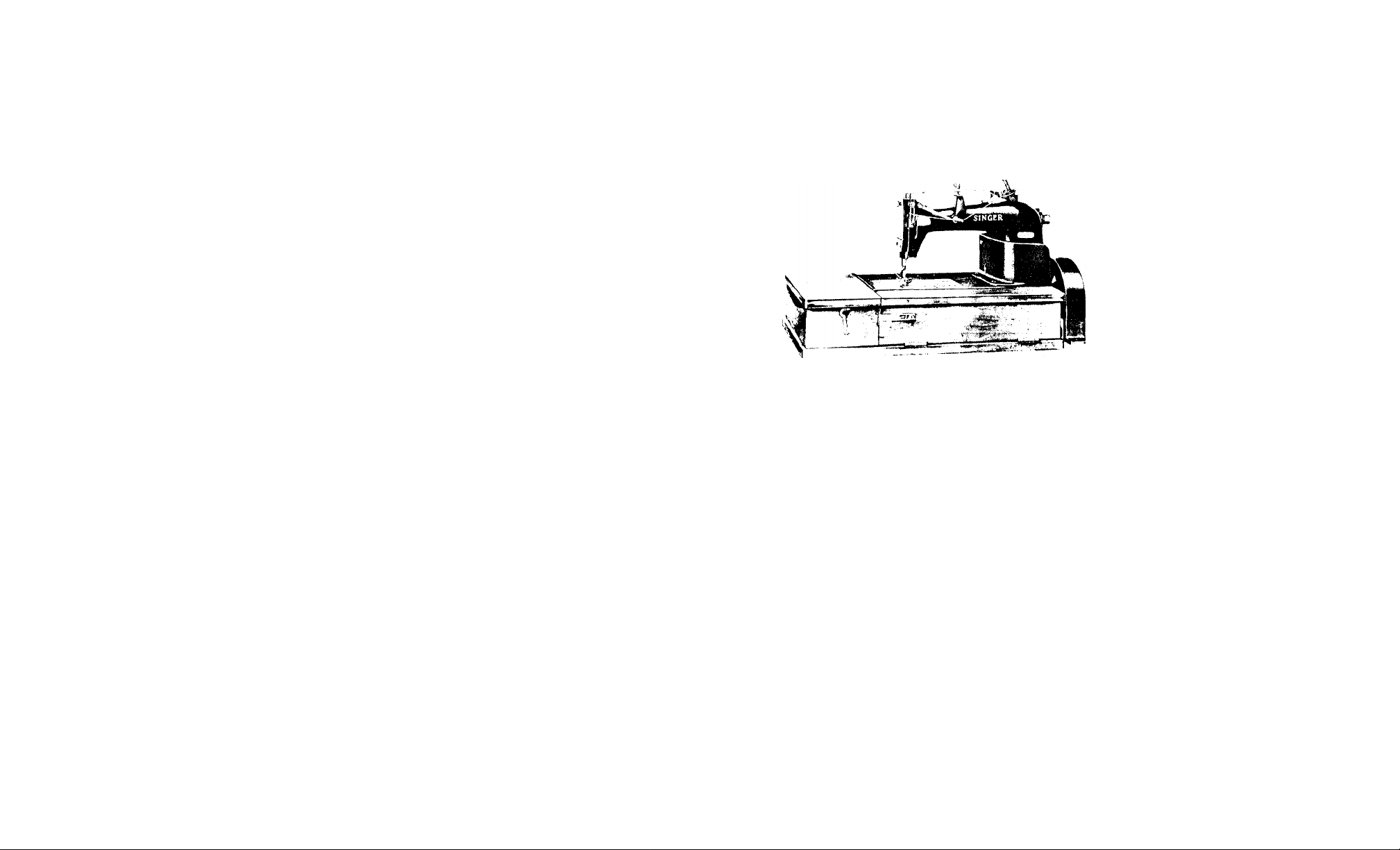
MACHINES
Nos. 147-82 and 147-86
THE SINGER MANiFACTURiNG COMPANY
Page 2

INSTRUCTIONS FOR OILING
To ensure easy running and prevent unnecessary wear of
the parts which are in movable contact, the machine requires
oiling and when in continuous use, "TYPE B" or "TYPE D" OIL,
sold only by Singer Sewing Machine Company, should be
applied at least twice each day to all oil boles marked
"OIL", as instructed in Form 18987.
"TYPE D" OIL is stainless.
SPECIAL NOTICE
The letter "O", marked on oil pipe couplings must always
be at the top. This is to insure that the oil spoon, attached to
the inner end of each coupling, is open side up.
INDEX
Accessories.................................................................................................. le
Belt guard
Bench Stand..................................................................................................... 16
Foot Lifter Parts................................................................................... 16
Knee Lifter Parts................................................................................... 17
Michlne Base.................................................................................................... 17
Machine Base Oil Drain Jar.................................................................... 18
Fbchlne No. 147-82
Machine No. 147-86
Numerical List of Parts.................................................................................... 21
Thread Unwinder............................................................................................. 18
....................................
..................................................................................
................................................................................
Page
16
15
5
Copyright, U. S. A., 1933, 1936 and 1937,
by The Singer Manufacturing Co.
All Rights Reserved for all Countries
Page 3
INSTRUCTIONS FOR ORDERING
In ordering from this list, use ONLY the part NUMBER In the
FIRST column.
The number stamped on a Sewing Machine Part Is In every
case the number of the single part only.
Every combination of parts sent out as such has Its spec
ific number, which, although not stamped on the parts, must be
used when ordering the combination.
Each number always Indicates the SAME PART In whatever list
It appears, or for whatever machine.
The letters after some of the numbers Indicate the style of
finish only, as follows:
A-Hardened, Polished, Nickel Plated and Buffed
B-Pollshed, Nickel Plated and Buffed
C-Hardened Only
D-Pollshed Only
E-Soft, Not Polished
F-Hardened and Polished
F.J-Hardened, Polished and Nickel Plated
Q-Brlght Rumbled and Nickel Plated
H-Blued
J-Nlckel Plated Only
K-Hardened and Nickel Plated
L-Brass Plated
M-Oxldlzed
N-Japanned, Dull
P-Japanned, Bright
R-Merllzed
S-Cadmlum Plating
T-Copper Plated
T.A-Hardened, Polished, Copper and Nickel Plated and Buffed
T.B-Copper and Nickel Plated and Polished
T.J-Copper and Nickel Plated Only
T.K-Hardened, Copper and Nickel Plated
T.M-Copper Plated and Oxidized
T.L-Copper and Brass Plated
U-Zlno Plated
V-Sllver Plated
V-Pollshed and Nickel Plated
Y-Black Nickel Plated Only
Z-Chromlum Plated
Z.B-PoiIshed, Nickel Plated, Buffed and Chromium Plated
Z.J-Nlckel and Chromium Plated
These letters MUST BE USED when they appear In the list;
and AFTER the number as In the list.
In this series:
1 to 1500, 50001 to 51500 and 140001 to 142000
e.re Screw Numbers
1501 to 1800 and 51501 to 51800 are Nut Numbers
1801 to 2000 and 51801 to 52000 are Roller Numbers
2001 to 50000 and 52001 to 140000 and 142001 to
190000 are Sewing Machine Parts, 190001 and upward
are numbers of Electrical Parts.
The figures In the second column refer only to the plates.
Illustrating the parts, and are NOT TO BE USED In ordering.
Parts narked with an asterisk (•) are furnished only when
repairs are made at factory.
LIST OF PARTS COMPLETE
FOR
MACHINE No. 147-82
For Seaming Medium and Medium Heavy Pants, Overalls
and Work of a Similar Nature. One needle, one looper. Ball
bearing. Needle bar stroke I 5/16 inches. The looper is arranged
so that it may be thrown out of position for convenience in thread
ing. An improved oiling system automatically oils all of the
principal hearings of the machine. Speed 4000 R. P. M.
No.
.Plate
131446
68428 20529
68429
50608R
139017
68350 20530
•68430
131309 20529
20529
1057C 20530
20530
20530 Arm
Arm,
, upper and lower (solid) with 948J,
15404,68483,two 15405 and four
131032
Arm
Bottom Cover........................................................
n
"
" " Screw
It
Hole Plug Screw, for access to Crank
Connecting Rod (upper bearing)
Hole Plug Screw Washer
(1
Oil Cup, for oiling Arm Rock Shaft
Front Bearing.........................................................
Arm
Oil Cup, for 131309
" " 68430 with 131310,for fill
ing oil reservoir.....................................................
Name
..................................................................
" Gasket (cork)
..................................
..............................................
...........................
......................................
..............................................
Page 4

No.
131305
131319 20530
131310
131293
131474
1309C 20530
131056
68433
68435 20550
131095
68436
131486 20560
50083C
131475 20550
127838
131456
42365 20530
54969 20530
1235F
131487 20561
131488
131366
131478
131479
131526
131369 20529
131370 20530
Plate
20529
20530
563C
20529
20550
20530
20550
20550
20530
446C
20550
20530
423C
20530
20530
20550
453C 20543
20530
Note; When No.
Looper Driving Shaft and Feed Lifting Eccentric
must be returned to the factory to. be adjusted
to the new part.
20550
20529
205C 20530
PARTS FOR MACHINE No. 147-82
Name
Arm
11
"
68350.
Arm
II
Rook Shaft.
II
and 131475.
Arm
" .
t1
II
II
(fibre),
Arm
"
Screw.
Arm
solid) with two 50083C.
Arm
"
II
Screw.
Arm
for oiling Back Bearing
Arm
Rock Shaft Oil Pad (braided cot
for oiling Intermediate Bearing.
Arm
"
Rotary Shaft.
131489 and 131502..............................................
" " " '' " " Case
Nos.131479,131480 and two 131366
Case Cap...............................................................
Case Cap Screw....................................................
Arm Rotary Shaft Ball Bearing (back)
Case Position Stud
on Pad (braided cotton) for
Arm Rotary Shaft 131487 with 640E,131111
Arm Rotary Shaft Ball Bearing (back)....
131478 with 131369 and three 205C...
Arm Rotary Sha.ft Ball Bearing (back)
Case with Ball Bearings complete.
Arm Rotary Shaft Ball Bearing (back)
Arm Rotary Shaft Ball Bearing (back)
Position Screw
131293 with 1235F,127838
Bushing (back),
" " Pin
Flanged Bushing (front)..
" " " Set
...............................
................................................
................
Washer.
Cap.
Washer
(Intermediate)...
" Set
(front) with 853C..
..........................
_________
No. Plate
429C 20530
131480 20539
131366 20550
131481 20550
1304C 20530
131482 20539
457C 20539
131457 20539
76IE 20530
42367 20530
54218 20530
144 D
20530
131276
131277
131280
51224W
131278
68448
1057K
131483
128510
51283C
131374
68368
131050
131051
131375
131381
131382
131388
101 IF 20533
50396F 20533
131394 20561
50473F 20533
20526
20526
20530
20530
20529
20530
20532
20532
20533
20561
20532
20532
725J
20533
20532
20532
725J
20533
389F 20533
PARTS FOR MACHINE No. 147-82
Arm Rotary Shaft Ball Bearing (back)
Case Set Screw
Arm Rotary Shaft Ball Bearing (back)
Spacing Collar
Arm Rotary Shaft Ball Bearing (Intermed
iate) .......................................................................
Arm Rotary Shaft Ball Bearing (intermed
iate) Case...............................................................
Arm Rotary Shaft Ball Bearing (Intermed
iate) Case Set Screw..............................................
Arm Rotary Shaft Ball Bearing (Intermed
iate) Collar with two 457C
Arm Rotary Shaft Ball Bearing (Intermed
iate) Collar Set Screw............................................
Arm Rotary Shaft Bushing (front)..................................
" " " " " Set Screw
" " " Front Bearing Oil Pad,
lower (braided cotton)
Arm Rotary Shaft Front Bearing Oil Pad,
upper (braided cotton)
Arm Rotary Shaft Screw.................................................
" Side Cover (oil vent)
" " " Cap
" " " '' Position Pin...............................
'' " " '' Thumb Screw............................
Arm Side Cover (oil vent) complete. Nos.
51224W,131276,131277 and 131280....................
Arm Side Cover Gasket (cork)...................................
" " " Screw...............................................
Balance Wheel, 2 in. pulley, with two
51283C...................................................................
Balance Wheel Cover.....................................................
" " Set Screw
Cloth Plate......................................................................
" " Slide (left).................................
" " " " Spring
" " " " " Screw...
Cloth Plate Slide (left) complete. Nos.
68368, 131050 and two 725J
Cloth Plate Slide (right)..................................................
" " ” ” Spring
" " " " " Screw...
Cloth Plate Slide (right) complete. Nos.
131375, 131381 and two 725J...............................
Cloth Plate complete,Nos. 131051, 131374
and 131382.............................................................
Cloth Plate Screw (left) for 131374................................
" " " (right)
" " Thread Guard
'' " " " Screw (lower)..
" " " " " (upper)..
Name
......................................................
.......................................................
....................................
...........................................
...........................................
.................................................
..................................................
...............................................
.................................
.................................
.................................
..
.....................
.....................
Page 5

e
No.
Plate
•131471 20550
131489
20533
896C
1057C
20530
68460 20532
68461 20532
330D
1053E
20533
20532
20533
20533
131395
29234
51224W 20530
735C
20551
20551
20551
20533
20533
20533
20533
131396
131397
131197
59343
134258
134259
68495 20533
134260
68467
207E
20533
20551
20533
131500 20551
131502
896C
20533
1057C 20530
68497
134260
131511
157J
20533
20533
20560
20533
50073J 20533
50429C
20533
•54024
7071
217J
11030
—
30533
20533
20533
20533
20551
20533
20551
•23729
510610
138306
54025
131240
PARTS FOR MACHINE No. IA7-82
Name
Crank Connecting Rod with two efeCh'''B96C
and 1057C............................................................
Crank Connecting Rod 131471 with 131486.
" " " Cap (lower) Screw..
" (upper) Screw..
Face Plate (lower half)..................................................
" " " " Oaaket (cork)..
Screw......................
" " (upper half)
M n (I It II II
..................................................
Position Plate..
Screw....................................................................
Face Plate (upper half) Thumb Screw...........................
Feed Bar
........................................................................
Feed Bar complete,Noa.50429C,68467,
131396 and two 207E
Feed Bar Hinge Pin (eccentric)
" ........................Collar with 735C
.
............................... " Set Screw...............................
" " Slide Block
.........................................
.....................................
......................
....................................................
" " " " 134258 with 68495
and 134260
Feed Bar Slide Block Oil Pad (wick)
...........................................................
............................
" " " " " Retainer...
Wearing Plate.............................................
" ” '' Screw
................................
Connecting Rod with 10570,68497,
134260 and two 896C
..........................................
Feed Connecting Rod 131500 with 54025...
" Cap Screw
" Clamping Screw
" " "on Pad (wick)
.............................
....................
.........................
" ” ................... Retainer
" Dog,16 teeth (10 teeth to the Inch)
for 131515
............................................................
Feed Dog Screw, when stationary Needle
Guard Is used........................................................
Feed Dog Sc^ew, when movable Needle
Guard Is used........................................................
Feed Dog Stop Screw....................................................
" Eccentric with 138306............................................
Body
.............................................
Set Screw...........................
Clamping Washer.
......
.................
Screw
Lubricating Pad (wood)...
Feed Eccentric (adjustable) complete.
Nos. 217J,1103C,7071,23729,54024 and
two 51061C
..........................................................
Feed Regulating Screw..................................................
" Rocking Frame with two 453C
..............................
________
...........
No.
Plate
131398
57234
20551
572-35 20533
4530 20543
4530 20543
131133
20535
131134
54027 20535
20535
175E
54227 20535
54228
20535
128419 20546
68478 20551
51263D 20546
68479 20535
20535
175E
131110
20551
Note
•131111
•68483
948J 20546
76 IE
20551
20546
20530
20533
68484
131028
68497
64315 20546
640E 20546
54035
51119J
131135
20535
20546
20535
46105 20535
229J 20535
PARTS FOR MACHINE No. 147-62
Name
Feed Rooking Frame 131240 with 59343,
131197 and 131397...............................................
Feed Rocking Frame Hinge Pin
.....................................
Bushing....
" Set
Screw.....................................................................
Feed Rocking Frame Hinge Pin Set Screw..
Looper............................................................................
—
“ 131133 with 229J and 131135..........................
" Carrier with two 175E.............................................
Adjusting Screw..............................
Connection
......................................
" Shaft
....................................
" " Oil Pad
(braided cotton).....................................................
Looper Carrier Connection Shaft Sleeve
(eccentric).............................................................
Looper Carrier Connection Shaft Sleeve
Cap Screw
.............................................................
Looper Carrier Driver with four 175E....
" " " Cap Screw............................
" Driving Shaft and Feed Lifting
Eccentric with two 64315......................................
When No. 131110 Is required for repairs, the
Arm Rotary Shaft must be returned to the fac
tory to be adjusted to the new part.
— Looper Driving Shaft and Feed Lifting
Eccentric 131110 with 54027,54227,
54228 and 68479...................................................
— Looper Driving Shaft and Feed Lifting
Eccentric Bracket with 761E.................................
Looper Driving Shaft and Feed Lifting
Eccentric Bracket Screw
.......................................
Looper Driving Shaft and Feed Lifting
Eccentric Bushing
.................................................
Looper Driving Shaft and Feed Lifting
Eccentric Bushing Oil Plug...................................
Looper Driving Shaft and Feed Lifting
Eccentric Bushing Position Screw....
Looper Driving Shaft and Feed Lifting
Eccentric Front Bearing Oil Pad
(wick)....................................................................
Looper Driving Shaft and Feed Lifting
Eccentric Oil Hole Plug
........................................
Looper Driving Shaft and Feed Lifting
Eccentric Screw.....................................................
Looper Holder with 1120C............................................
" " Screw.......................................................
" Needle Guard with 46105.....................................
" " " Pin.......................................
" " " Screw
..................................
Page 6

10
PARTS FOR MACHINE No. 147-в2
PARTS FOR MACHINE No. 147-82
11
No.
1120C
68485
68486
43503
54208
131291
1133E
64320
1133E
68488
131399
68489
131270
131400
1492E
131316
68123
131315
54038
68492
68493 20538
68494 20538
•49189
68495 20533
68496 20538
Plate
20535
20551
20546
20546
20546
4430
20560
20552
20552
20552
20552
20552
20552
1520J
20552
20552
8610
20552
8530
20552
20543
20552
20552
20552
20560
20552
176J
20552
2170
20533
8570
20560
20538
176E 20552
-------
198E 20546
Name
Looper Set Screw..........................................................
" Throw-out Handle with two 4430...
'' " '' Plunger............................
" " " " Spring...
" " " Set Screw
Needle Bar (hollow) with 8570.....................................
" '' Bushing (lower)
" " " " Set Screw
" ” " (upper)
" " " " Set Screw
" " Connecting Link and Thread
(upper) Controller
Needle Bar Connecting Link and Thread
and 131400
Needle Bar Connecting Link Hinge Stud
(hollow)
Needle Bar Connecting Link Hinge Stud
Nut........................................................................
Needle Bar Connecting Link Hinge Stud
Oil Pad (wick)
Needle Bar Connecting Link Hinge Stud
Oil Plug Screw......................................................
Needle Bar Connecting Link Hinge Stud
Set Screw..............................................................
Needle Bar Connecting Stud with 211K and
1492E...................................................................
Needle Bar Connecting Stud Clamping
Screw....................................................................
Needle Guard (movable)...............................................
Hinge Pin Front Bearing.......................................
Oil Pipe (back of arm) Clamp
" "
" " " " " Connection with
48189,68495 and two 198E, for oiling
Feed Rocking Frame Hinge Pin Back
Bearing.................................................................
Oil Pipe (back of arm) Connection Cap...
II II И II II II . II
Screw...........................................................
Oil Pipe (back of arm) Connection Oil
Pad (wick)
Oil Pipe (back of arm) Coupling...................................
(upper) Controller 68468 with 68489
...........................................................
..................
......................................................
(stationary)
Screw................................................
Set Screw
.......................................................
Oil Pipe (back of arm) with 49191 and
68497, for oiling Peed Rocking Frame
.
..................
............................................................
......................................
.........................................
................................................
*............................................
" Clamp....................................
.......................................
" Holder.....................
" " Screw
.......................................
" Screw
..................
..............
..............
-------
...........................
..
No.
1733
Plate
20546
68497 20533
49191
—
68498 20538
131112 20538
68500 20538
131113 20538
131258
131002 20538
131003 20538
131084 20538
•49189 --------
•131049
•131085
131004
131004
131086
131087
131088
131089 20546
68497 20533
•49191
64330
25303
198E 20546
1733
--------
--------
--------
20538
20538
20538
20546
20542
20546
Name
on
(brass),
on
"
II
Looper Driving Shaft and Feed Lift
Oil Pipe (front of arm) with 68497 and
Block.....................................................................
Oil Pipe (front of arm) with 1733,49191,
Rotary Shaft Front Bearing
Oil Pipe (front of arm) with 68497 and
Rod
Oil Pipe (front of arm) complete, Nos.
68498,68500,131112 and 131113
Oil Pipe (front of arm) Connection with
er Throw-out Device
Oil Pipe (front of arm) Connection with
49189 and two 198E,for 131112 and
" Sleeve...........................
(front of arm) with 131089 and
two each 1733 and 49191,for oiling
ing Eccentric Front Bearing
131003, for oiling Feed Bar Slide
131004 and 131089,for oiling Arm
131003, for oiling Feed Connecting
........................................................................
131049 and two 198E,for oiling Loop
131113...................................................................
..................................
...................................
.........................
.............................................
oil Pipe (front of arm) Connection with
131085 and two 198E, for 68500
Oil Pipe (front of arm) Connection Cap,
for 131003
Oil Pipe (front of arm) Connection Cap,
for 131002
Oil Pipe (front of arm) Connection Cap,
for 131084
Oil Pipe (front of arm) Connection Cap
Screw.....................................................................
Oil Pipe (front of arm) Coupling (center)
" " " " " " (left).
.........................
n II II II II l> M
131086 with 131088
.............................................................
.............................................................
.............................................................
- “ " " (right)
...........................................
.......................
on Pipe (front of arm) Coupling (right)
on Lead
...............................................................
on Pipe (front of arm) Coupling Nut
(brass)....................................................................
on Pipe (front of arm) Oil Pad (wlok)
for 68498 and 68500
.............................................
on Pipe (front of arm) Oil Pad (wick)
for 131112 and 131113..........................................
on Pipe (front of arm) Sleeve
Presser Bar with 25303..................................................
" " Ball, size 1/4 In........................................
.......................................
Page 7

12
No.
Plate
131006 20543
1133E 20552
38456
20543
1133E 20552
131401
11173
20543
20543
453C 20543
453C 20543
131402
20542
68184 20542
16IJ 20546
802D 20546
38467
38468
■131231
20542
20543
—
'131232
4604 20560
131198
26276
131512
20561
20546
—
131513
190J
574W
20560
20530
20543
20543
131514
1539W
131025 20543
54242
20553
190J 20530
131419
131404
131405
20540
20540
20540
1423J 20540
171E 20540
217J
69 IF
20540
20533
20542
20540
131406
131012
2102 20540
51570C 20540
50326C
20540
59539
59534
20540
PARTS FOR MACHINE No. 147-02
Name
Presser Bar Bushing (lower)
.........................................
" " Set Screw
(upper)...............................
'' Set Screw....
Lifting Bracket with 453C...
" " Guide.................
" " Set Screw
" Set Screw...
Lever
.................................
" " Extension
" " '' Screw.
" Hinge Screw...
Spring (flat)
.........................................
Stud......................................
(auxiliary)............................
" Guide
" " " Rivet
Presser Bar Spring (auxiliary) complete,
Nos. 4604,131231 and 131232
Presser Foot Hinge Pin
................................................
.............................
" " Plate....................................................
" " Shank..................................................
Presser Foot (hinged) complete,Nos.26276
131512 and 131513
Presser Foot Screw
Pressure Regulating Thumb Screw
..............................................
.......................................................
...............................
" " Lock Nut.
Slack Thread Controller
” " " Clamp
................................................
....................................
Screw
Regulator...........................................
” " " Holder....................................
171E
.....................................................................
Slack Thread Regulator Holder Crank Cap
Screw....................................................................
Slack Thread Regulator Holder Crank
Clamping Screw
...................................................
Slack Thread Regulator Holder Crank
Connecting Link
Slack Thread Regulator Screw
...................................................
......................................
Tension (under thread) Bracket.....................................
" " ” " Screw
" " " Disc
.....................................
Regulating Thumb
Nut.........................................................................
Tension (under thread) Screw Stud
...............................
" " “ " " 50326C
with 51570C..........................................................
Tension (under thread) Spring.......................................
________
...............
...........
.................
Crank with
-------------
No.
59537
Plate
20540
59530 20540
376J
6240
316C
1547J
20540
20560
20540
20540
20540
20540
20540
20560
20539
20539
20539
20539
20539
20539
20539
20540
57076
54045
2102
51570C
32572
54988
54046
54047
54048
68261
131011
50326C
59539
190J
190J
20540
20540
20540
20540
20539
20530
20539
20553
20553
20539
20553
20553
20530
20542
20542
59535
59537
59538
57076
53225
131407
131408
50438J
1258C
131409
54242
131410
131411
PARTS FOR A4ACHINE No. 147-02 13
Name
Tension (under thread) Spring Bushing
(large)
...............................................................
Tension (under thread) Spring Bushing
(small)...................................................................
Tension (under thread) Thread Guide
" (upper thread) Bracket
............................
..........................................
" " " ” Screw....
" " " Disc
..............................
” " " Regulating Thumb
Nut.........................................................................
Tension (upper thread) Releasing Disc...
" '' " " Pin
" " " " Shaft..
nun It II
Crank with 6240
....................................................
_____
Tension (upper thread) Releasing Shaft
Crank Link.............................................................
Tension (upper thread) Releasing Shaft
Crank Set Screw
....................................................
Tension (upper thread) Releasing Shaft
Spring
....................................................................
Tension (upper thread) Releasing Shaft
Spring Position Plate
.............................................
Tension (upper thread) Releasing Shaft
Stop Screw.............................................................
Tension (upper thread) Releasing Shaft
Stop Screw Nut......................................................
Tension (upper thread) Screw Stud
................................
” " " " " 50336C
with 51570C
..........................................................
Tension (upper thread) Spring........................................
" " " " Bushing
(large)....................................................................
Tension (upper thread) Spring Bushing
(small)
...................................................................
Tension (upper thread) Thread Guide
(double)...............................................-
................
Thread (under) Eyelet (back)..........................................
" " " " Screw
" " Take-up with 12580
" " "on Guard
" "
.........................
" " " Set Screw
" " " Stripper
" " " " Clamp...
•I II II II >1
....................
..............................
...............................
Screw...
.............................
................................
Screw.....................................................................
Thread (under) Take-up Stripper Plate...
II II II II n
Bracket
..................................................................
Page 8

14
PARTS FOR MACHINE No. I47-82
15
No. Plate
131420
965D 20553
1901 20530
32082 20553
131413
20553
504701 20553
131421 20553
2071
20533
7071
131422
7071
38484
2071
20533
20553
20533
20533
20643
1901 20530
131332 20543
64194
68164
20543
20543
14491 20543
131333
211F 20543
742F
20560
20560
131515
•15404
15405
Name
Tliread (under) Take-up Stripper Plate
Bracket 131411 with 32062,50438J,
54242,131408 to 131410,131413,131421
131422,two each 207J,7071,504701 and
four 190J
................
..............................................
Thread (under) Take-up Stripper Plate
Bracket Screw.......................................................
Thread (under) Take-up Stripper Plate
Screw....................................................................
Thread (under) Take-up Stripper Washer..
" " " Thread Guard
UIbre)...................................................................
Thread (under) Take-up Thread Guard
Screw
....................................................................
Thread (under) Take-up Thread Guide
(left)......................................................................
Thread (under) Take-up Thread Guide
(left) Screw...........................................................
Thread (under) Take-up Thread Guide
(left) Screw Washer..............................................
Thread (under) Take-up Thread Guide
(right)
...................................................................
Thread (under) Take-up Thread Guide
(right) Screw.........................................................
Thread (under) Take-up Thread Guide
(right) Screw Washer
...........................................
Thread (upper) Eyelet....................................................
" " " Screw....................................
" " Take-up.................................................
" " " Plate......................................
" " " " Spring
" " «...
Thread (upper) Take-up complete,Nos.
14491,54194,68164 and 131332
Thread (upper) Take-up Set Screw
Throat Plate, for 131511
" " Screw
—
Trade Mark....................................................................
—
" " Rivet..........................................................
...............................................
....................................................
..........................
...............................
.....................
A\ACHINE No. 147-86
For Pants Seaming, for Medium and Heavy Work. One
needle, one looper. Ball bearing. Needle bar stroke I 3/8 inches.
The looper is arranged so that it may be thrown outof position
for convenience in threading. An improved oiling system auto
matically oils all of the principal bearings of the machine.
Speed 3800 R. P. M.
THIS MACHINE IS THE SAME AS THE 147-82 MACHINE,
WITH THE FOLLOWING EXCEPTIONS;
No.
131072
Plate
20550
131510
68459
131505 20552
131292
20560
Arm Rock Shaft Crank, back (ball bearing
solid) with two 50083C, In place of
131486..................................................................
Arm Rotary Shaft 131487 with 640E,68459,
131111 and 131502,ln place of 131488
Crank Connecting Rod 131471 with 131072,
in place of 131489................................................
Needle Guard (stationary) In place of
131315..................................................................
Presser Bar Bushing (lower) in place of
131006..................................................................
Name
Page 9

16
FOOT LIFTER PARTS
17
ACCESSORIES
No.
120344
120345
120440
121108 20545
120341
4822
Plate
20545
20545
20545
20545
20545
8908 20545
Oiler (copper plated) with 120345.
" Spout, 4 1/2,In. long..................................
Screw Driver (large)
" " (small)........................................
Tweezers (curved)............................................
Wrench for 1547
" " 1520
Name
........................................
..............................................
.........................................
BELT GUARD
No.
68222
Plate
20549
Belt Guard with two wood screws 1 In.No.
12
...........................................................
Name
BENCH STAND
No.
79772
126849
37998
126247
126248
41538
60656
Plate
9520
9520
9520
9520
9520
Bench Stand with 27998,two each 4153S,
126849,three wood screws 1 1/4 In.
No. 12, foui each 60656,wood screws
1 1/4 in. No.10 and sixteen wood
screws 5/8 In. No. 7
Flap Hinge with four wood screws 3/4 In.
No. 7.....................................................................
Flap Hook and Eye (brass) with wood
screw 1/2 In. No. 5...............................................
Flush Bolt.....................................................................
" " Plate
Flush Bolt with Plate complete. Nos.
126247,126248 and four brass wood
screws 5/8 In. No. 4.............................................
Hinge............................................................................
Name
.............................................
............................................................
FOOT LIFTER PARTS
No. Plate Name
6439
-------
Chain,36 In.to 45 In.,with 56864 and
Note; When ordering No.6439,state length required.
4879 20545 Chain Connecting Link
56864 20545 " Hook (large)
56865 20545 " " (snail)..........................................................
56865
............................................... ..................
........................................................
..........................................................
No.
126249
4882
126250 20547 " Spring
150451 20549
150452
Plate
20549
20547
20549
" Shaf t.....................................................................
" Stand.....................................................................
Treadle complete,Nos.4879,4882,126249,
126250,150451 and two wood screws 1
In. No. 16 F.H.......................................................
Name
...................................................................
KNEE LIFTER PARTS
No. Plate Name
37563 -------- Chain,length 15 in.,with 56864 and 56865
56864 20545 " Hook (large)............................................................
56865 20545 " " (small)........................................................
2763 20561 Rock Shaft...............................................................................
12242 20561 “ " Hanger with two wood screws 1
In. No. 10..............................................................
6335 20561 Rock Shaft Knee Arm
6336
2766 20561 Rook Shaft Knee Arm Hub with 356C....................................
2767 20561 " " " Plate with 3560
6337 20561 " " Lifting Bracket with two 356C
7125 20561 " " " " Hook
2770 20561 " " Stop Dog with 356C
23767 20561 Rock Shaft complete,Nos.2763,2770,6336,
--------
Rock Shaft Knee ,Arm complete,Nos.2766,
2767 and 6335.......................................................
356C 20546 " " " " " Set Screw
356C 20546 " '' " " Set Screw
356C 20546 " " " " " Set Screw
356C 20546 " " " ” Set Screw
356C 20546 " " " " Set Screw................................
6337,7125 and two 12242
.............................................................
.......................
............................
.............................
....................
____
..................................
.....................................
MACHINE BASE
No. Plate
131263
54477
131205 20547
51576E 20547
9842 20547
131022 20547
131279
131264
20549
20547
20547
Machine Base.................................................................
" " Screw Stud, to fasten base
to table
Machine Base Screw Stud,to position ma
chine on base.........................................................
Machine Base Screw Stud Nut.......................................
" '' " " " Washer..................
" " “ " Bushing (rubber)
“ Cushion (felt)
Machine Base complete,Nos.131263, three
each 9842,51576E,54477 and four each
131205 and 131279
Name
..................................................................
.......................................................
..............................................
Page 10

18
No. Plate Name
131328
-------
Machine Вазе and Oil Drain Jar (swinging
MACHINE BASE
type) complete,Nos.131264 and 131268
MACHINE BASE OIL DRAIN JAR
(SWINGING TYPE)
No. Plate Name
131185 20526 Jar (glass).....................................................................
131191 20526 " Cap.........................................................................
131188 20526 " Clamp.....................................................................
131217 -------- " " 131188 with 131189................................
131189 20526 " " Lever..............................................................
1247C 20546 '' " " Hinge Screw
131265 20526 Nipple (long)
131266 20526 " (short)
131267 20526 " Elbow...............................................................
131268
-------
Machine Base Oil Drain Jar (swinging
..........................................................................
..............................................................
type) complete,Nos. 131185,131191,
.131217,131266 and two each 1247C,
131265 and 131267
.....................................
..............................................
THREAD UNWINDER
THREAD UNWINDER
No.
150087
Plate
-----
Thread Separator complete,Nos.164J,9525,
150060 and 150086
Name
..........................................
150088 20787 Thread Unwinder complete,Nos.150087,
201696J, 208490,285257,225384, .885386,
225388, two each 150203,825^1 and
three wood screws 7/8 In.No.12
.....................
27739 20561 Thread Cone (wood) for large cones..............................
235390 20561 " " Holder, for Inverted cones..
Note: Nos. 27739 and 225390 are used with, but not
Included In 150088.
19
No. Plate
225257 20787
150203
225388
200383C 20546
201018C 20546
202490
225391
201696J
225326 20546
225324
225322 20546
150085
150086
150059
150060 20787
9525
9525 20546
20787
20787
20787
20787
20546
20787
20 8E 20546
20787
164J 20546
20546
164J 20546
FOR TWO SPOOLS
Name
Spool Rest (for two spools) with 201018C
" " Cushion (felt)...............................................
" " Rod
" Stand with 200383C...............................................
Thread Guide.................................................................
" " Lock Nut
■' " Position Cup............................................
" " Rod with 208E and 225322...
" " " Screw
.........................
" Separator
" ” 150085 with 150059
" " " Arm with 164J
and 9525................................................................
Thread Separator Bracket Arm Clamping
Screw
Thread Separator Bracket Arm Clamping
Screw Washer
Thread Separator Bracket Arm Screw...........................
" " " " " Washer
..............................................................
Set Screw......................................
Set Screw...............................................
.....................................
......................................
Washer...........................................
..............................................................
................
Bracket
.....................................
....................................................................
.......................................................
SINGER Needles should be used
in SINGER Machines.
These Needles and fheir Containers
are marked with the
Company's Trade Mark “SIMANCO.'* *'
Needles in Containers marked
“FOR SINGER MACHINES"
are NOT SINGER made needles.
Page 11

:ол
. ^
...........
-......................_-v
;, 'Л >
21
NUMERICAL LIST OF PARTS
'V ■■■
NUMERICAL
LIST
OF PARTS
■;, . -V ; ^
k-‘
V/ ' ..'ip
\
■> -’‘г
ivC
.-. - С J"' лМ/'
‘ .".f■!*.:-;
... "0
L, A.,
■ n
a=®-
■■■■4' :
No. Plate Name
144D 20530 Arm Rotary Shaft Screw.........................................................
157J 20533 Feed Dog Screw,when stationary Needle
161J 20546 Presser Bar Lifting Lever Extension
164J 20546 Thread Unwinder Thread Separator Bracket
164J 20546 Thread Unwinder Thread Separator Bracket
171E 20540 Slack Thread Regulator Holder Crank
175E 20535 Looper Carrier Adjusting Screw,for 54027
175E 20535 " " Driver Cap Screw,for 68479
176J 20552 Needle Guard (stationary) Holder Screw..
176E 20552 on Pipe (back of arm) Clamp Screw
190J 20530 FTesser Foot Screw
190J 20530 Slack Thread Controller Clamp Screw
190J 20530 Thread (under) Eyelet (back) Screw.......................................
190J 20530 " " Take-up Stripper Clamp
190J 20530 Thread (under) Take-up Stripper Plate
190J 20530 Thread (upper) Eyelet Screw
1Э8Е 20546 Oil Pipe (back of arm) Connection Cap
198E 20546 on Pipe (front of arm) Connection Cap
205C 20530 Arm Rotary Shaft Ball Bearing (back)
207E 20533 Feed Bar Wearing Plate Screw,for 131397.
207J 20533 Thread (under) Take-up Thread Guide
207J 20533 Thread (under) Take-up Thread Guide
208E 20546 Thread Unwinder Thread Guide Rod Screw,
211F 20543 Thread (upper) Take-up Set Screw, for
217J 20533 Feed Eccentric Clamping Washer Screw,for
217C 20533 Needle Guard Screw
217J 20533 Slack Thread Regulator Screw................................................
229J 20535 Looper Needle Guard Screw,for 131134....
316C 20539 Tension (upper thread) Releasing Shaft
330D 20533 Face Plate (lower half) Screw.........................................
356C 20546 Rock Shaft Knee Arm Hub Set Screw, for
Guard 13 used
Screw
Arm Clamping Screw, for 150060
Arm Screw, for 150087.........................................
Clamping Screw, for 131405
Screw, for 131420
Screw, for 131420.................................................
Screw, for 68494...................................................
Screw, for 131002,131003 and 131084.
Case Cap Screw, for 131479.................................
(left) Screw, for 131420
(right) Screw, for 131420
for 225324.............................................................
131400..................................................................
54025.....................................................................
Stop Screw
2766.......................................................................
.......................................................
....................................................................
........................
................................
..........................................
................................................................
.......................................
.................................................
..................................................
.......................................
.....................................
...............................................................
............................................................
Page 12

за
No.
Plate
20546
356C
20546
356C
20546
356C
20546
356C
20540
376J
20533
389F
20530
423C
20530
429C
20546 Looper Throw-out Handle Set Screw, for
443C
20530 Arm Rock Shaft Bushing (back) Set Screw.
446C
453C 20543
20543
453C
453C 20543
453C 20543 Presser Bar Lifting Bracket Guide Set
20543 Presser Bar Lifting Bracket Set Screw,
453C
20539
457C
20530
563C
574W 20543 Pressure Regulating Thumb Screw
20539
624C
640E 20546
20540
69 IF
725J
20533
725J
20533
735J
20533
742F 20560
76 IE 20530 Arm Rotary Shaft Bushing (front) Set
76 IE 20530
802D 20546 Presser Bar Lifting Lever Hinge Screw.-.
853C 20552
NUMERICAL LIST OF PARTS
Name
Rock Shaft Knee Plate Set Screw,for 2767
Screw, for 6337
Rock Shaft Lifting Bracket Set Screw,for
6337......................................................................
Rock Shaft Stop Dog Set Screw,for 2770..
Tension (upper thread) Bracket Screw....
Cloth Plate Thread Guard Screw (lower)..
Arm Rook Shaft Bushing (intermediate)
Set Screw..............................................................
Arm Rotary Shaft Ball Bearing (back)
Case Set Screw
68485....................................................................
Set Screw..............................................................
Feed Rocking Frame Hinge Pin Bushing Set
Screw....................................................................
Feed Rocking Frame Hinge Pin Set Screw,
for 131240
Screw....................................................................
for 131401
Arm Rotary Shaft Ball Bearing (Intermed-
late) Collar Set Screw,for 131482...
Arm Oil Cup Drip Pan Position Screw, for
131305..................................................................
Tension (upper thread) Releasing Shaft
Crank Set Screw, for 54047
Eccentric Screw,for 131488 and
131510..................................................................
for 131051
for 131382
59343
Throat Plate Screw
Screw
Eccentric Bushing Position Screw,for
68483
Set Screw, for 131475...........................................
Looper Driving Shaft and Feed Lifting
Tension (under thread) Bracket Screw....
Cloth Plate Slide (right) Spring Screw,
Feed Bar Hinge Pin Collar Set Screw, for
....................................................................
....................................................................
Looper Driving Shaft and Feed Lifting
....................................................................
Needle Bar Connecting Link Hinge Stud
" '' Lifting Bracket Hook Set
....................................................
.....................................................
" " " Flanged Bushing (front)
............................................................
............................................................
...............................
.................................
Cloth Plate Slide (left) Spring Screw,
............................................................
............................................................
........................................................
No.
2102
2102
2763 20561
Plate
20560
857C
861C 20552
896C 20533
20533
896C
948J 20546
965D
20553
lOllF 20533
1053E 20533
1057C
1057K
1057C
1057C
1103C
1120C
1133E
1133E
1133E
1133E 20552
1235F
1247C
1258C
1304C
1309C
1423J
1449J
1492E
1520J 20552
1539V
1547J
1733
1733 20546
20530
20530
20530
20530
20533
20535
20552
20552
20552
20530
20546
20539
20530
20530
20540
20543
20552
20543
20539
20546
20540
20540
NUMERICAL LIST OF PARTS
Name
Needle Set Screw, for 54208
Oil Plug Screw
Crank Connecting Rod Cap (lower) Screw,
for 131471............................................................
Feed Connecting Rod Cap Screw,for 131500
Looper Driving Shaft and Feed Lifting
Eccentric Bracket Screw,for 131446..
Bracket Screw
Cloth Plate Screw (left) for 131374
Face Plate (upper half) Position Plate
Screw....................................................................
Arm Bottom Cover Screw.............................................
" Side Cover Screw.....................................................
Crank Connecting Rod Cap (upper) Screw,
for 131471
Feed Connecting Rod Clamping Screw, for
131500..................................................................
Feed Regulating Screw, for 54025
Looper Set Screw, for 54035.........................................
Needle Bar Bushing (lower) Set Screw....
" " ” (upper) Set Screw..,.
Presser Bar Bushing (lower) Set Screw...
" " " (upper) Set Screw...
Arm Rock Shaft Oil Plug Screw,for 131474
Machine Base Oil Drain Jar Clamp Lever
Hinge Screw, for 131268
Thread (under) Take-up Set Screw, for
131407
Arm Rotary Shaft Ball Bearing (intermed
iate) Case Set Screw
Arm Rock Shaft Adjusting Screw..................................
Slack Thread Regulator Holder Crank Cap
Screw.....................................................................
Thread (upper) Take-up Plate Spring
Screw, for 131333
Needle Bar Connecting Stud Clamping
Screw, for 131400
Needle Bar Connecting Link Hinge Stud
Nut.........................................................................
Pressure Regulating Thumb Screw Lock Nut
Tension (upper thread) Releasing Shaft
Stop Screw Nut
Oil Pipe (back of arm) Coupling Nut
(brass)
Oil Pipe (front of arm) Coupling Nut
(brass) for 68498 and 68500
Tension (under thread) Disc...........................................
" (upper thread) Disc
Rock Shaft, for 23767
Thread (under) Take-up Stripper Plate
............................................................
..................................................................
...................................................................
........................................
Bar Connecting Link Hinge Stud
.....................................................
......................................................
..............................
................................
......................................
.............................................
.................................................
.................................................
.....................................................
.................................
...............................................
....................................................
23
Page 13

34
No. Plate
2766 20561
2767 20561
2770 20561
4604
4822
4879
4882
6335 20561
6336
6337
6439
7071
7071
7071
7125
8908
9525
9525
9842
11173
12242
•15404
15405
'23729
23767
25303 20546
26276
27739
27998
29234
32062
32572
37563
38456
38467
20560
20545
20545
20547
20561
20533
20533
20533
20561
20545
20546
20546
20547
20543
20561
20561
20546
20561
9520
20533
20553
20540
20543
20542
NUMERICAL LIST OF PARTS
Name
Rock Shaft Knee Arm Hub with 356C, for
6336......................................................................
Rock Shaft Knee Plate with 356C,for 6336
" " Stop Dog with 356C, for 23767
Ргеззег Bar Spring (auxiliary) Guide
Rivet, for 131198..................................................
Vrench for 1547 (Acce33orles)
Chain Connecting Link, for 150452..............................
Treadle Shaft, for 150452..............................................
Rock Shaft Knee Arm, for 6336....................................
Rock Shaft Knee Arm complete for 23767,
Nos. 2766, 2767 and 6335
Rock Shaft Lifting Bracket with two 356C
for 23767
Chain,36 In.to 45 In.,with 56864 and
56865....................................................................
Feed Eccentric Clamping Washer,for 54025
Thread (under) Take-up Thread Guide
(left) Screw Vlaaher, for 131420
23767....................................................................
Wrench for 1580 (Accessories)
Arm Screw Washer, for 150087
Pbchlne Вазе Screw Stud Nut Washer, for
131264..................................................................
Presser Bar Lifting Bracket Guide................................
Rock Shaft Hanger with two wood screws 1
In. No. 10, for 23767
Trade №rk, for- 131446................................................
" " Rivet, for 131446
Feed Eccentric Body, for 54025
Rock Shaft complete,Nos.2763,2770,6336,
6337,7125 and two 12242....................................
Presser Bar Ball, size 1/4 In.,for 64330
" Foot Hinge Pin, for 131514.................................
Thread Cone (wood) for large cones
79772
Face Plate (upper half) Position Plate..
Thread (under) Take-up Stripper Washer,
for 131420............................................................
Tension (upper thread) Releasing Disc...
Chain,length 15 In.,with 56864 and 56865
Presser Bar Bushing (upper)
..............................................................
Thread (under) Take-up Thread Guide
(right) Screw Washer, for 131420....
Rock Shaft Lifting Bracket Hook, for
Thread Unwinder Thread Separator Bracket
Arm Clamping Screw Washer,for 150060
Thread Unwinder Thread Separator Bracket
Bench Stand Flap Hook and Eye (brass)
with wood screw 1/2 In.No.5, for
...................................................................
Spring (flat)'........................................
.....................................
....................................
.........................
.....................................
...........................
...........................................
........................................
...................................
............................
........................................
NUMERICAL LIST OF PARTS
No. Plate Name
38468 20543 Presser Bar Spring Stud...........................................................
38484 20543 Thread (upper) Eyelet
41538
42365 20530 Arm Rock Shaft Oil Pad (braided cotton)
42367 20530 Arm Rotary Shaft Front Bearing Oil Pad,
43503 20546 Looper Throw-out Handle Plunger Spring..
46105 20535 " Needle Guard Pin, for 131135
•49189
•49189
•49191
•49191
50073J 20533 Feed Dog Screw,when movable Needle Guard
50083C 20530 Arm Rock Shaft Crank (back) Set Screw,
50326C 20540 Tension (under thread) Screw Stud, for
50326C 20540 Tension (upper thread) Screw Stud, for
50396F 20533 Cloth Plate Screw (right)
50429C 20533 Feed Dog Stop Screw, for 131397
50438J 20553 Thread (under) Take-up Oil Guard Screw,
50470J 20553 Thread (under) Take-up Thread Guard
50473F 20533 Cloth Plate Thread Guard Screw (upper)..
50608R 20530 Arm Hole Plug Screw,for access to Crank
51061C 20533 Feed Eccentric Body Set Screw,for 54025.
51119J 20546 Looper Holder Screw...............................................................
51224W 20530 Arm Side Cover Cap Thumb Screw, for
51224W 20530 Face Plate (upper half) Thumb Screw
51263D 20546 Looper Carrier Connection Shaft Sleeve
51283C 20533 Balance Wheel Set Screw, for 131483.....................................
51570C 20540 Tension (under thread) Regulating Thumb
51570C 20540 Tension ( upper thread) Regulating Thumb
51576E 20547 Machine Base Screw Stud Nut. for 131264.
53225 20539 Thread (under) Eyelet (back)
•54024
--------
Bench Stand Flush Bolt with Plate com
--------
on Pipe (back of arm) Connection Cap,
--------
on Pipe (front of arm) Connection Cap,
--------
on Pipe (back of arm) Sleeve,for 68492.
--------
" " (front of arm) Sleeve,for 68498
--------
Feed Eccentric with 133306, for 54025...
plete for 79772, Nos. 126247,126248
and four brass wood screws 5/8 in.
No. 4
for oiling Back Bearing
lower (braided cotton)
for 68494
for 131003
and 68500...............................................................
Is used....................................................................
for 131072 and 131486..........................................
59539.....................................................................
59539.....................................................................
for 131420
Screw, for 131420..................................................
Connecting Rod (upper bearing)
131278...................................................................
Cap Screw
Nut, for 59539
Nut, for 59539........................................................
..............................................................
......................................................................
.........................................
...........................................
..............................
...............................................................
.............................................................
.........................................................
...........................................
.............................................................
...........................
........................................
.............................................................
.......................................................
..........................................
26
Page 14

26 NUMERICAL LIST OF PARTS
NUMERICAL LIST OF PARTS
27
No. Plate Name No.
54025 20551
Feed Eccentric (adjustable) complete for
131502, Nos.217J,n03C, 7071,23729,
54024 and two 51061C.........................................
54027
54035
54038
54045
54046 20560
5404 7
20535
20535
20552
20560
20539
Looper Carrier with two 175E,for 131111.
" Holder with 1120C...............................................
Needle Guard (stationary) Holder
.................................
Tension (upper thread) Bracket.....................................
tl II II n II
Releasing Shaft..
Crank with 624C...................................................
54048 20539
Tension (upper thread) Releasing Shaft
Crank Link............................................................
54194
54208
54218
54227 20535
54228
20543
20560
20530
20535
Needle Bar (hollow) with 857C
Thread (upper) Take-up Plate, for 131333
Arm Rotary Shaft Front Bearing Oil Pad,
upper (braided cotton)
..........................................
Looper Carrier Connection, for 131111...
" " " Shaft, for
....................................
131111..................................................................
54242
54242
20553
20553
Slack Thread Controller Clamp.....................................
Thread (under) Take-up Stripper Clamp,
for 131420.............................................................
54477
20547
Machine Base Screw Stud,to fasten base
to table, for 131264..............................................................................
54969
54988
56864 20545
56865
57076
57076 20540
57234
57235
59343
20530
20540
20545
20540
20551
20533
20533
Arm Rock Shaft Oil Pad (braided cotton)
for oiling Intermediate Bearing
Tension (upper thread) Releasing Pin...,
Chain Hook (large) for 6439 and 37563... 68478 20551
" " (small) for 6439 and 37563...
Tension (under thread) Thread Guide
(upper thread) Thread Guide
(double)
................................................................
Feed Rocking Frame Hinge Pin
" "
................................................
....................................
Bar Hinge Pin Collar with 735C,for
............................
...........................
Bushing....
131398..................................................................
59534
59535 20540
59537
20540
20540
Tension (under thread) Spring
(upper thread) Spring...................................
(under thread) Spring Bushing
.......................................
(large)...................................................................
59537
20540
Tension (upper thread) Spring Bushing
(large)...................................................................
59538
20540
Tension (under thread) Spring Bushing
(small)...................................................................
59538
20540
Tension (upper thread) Spring Bushing
(small)...................................................................
59539
Tension (under thread) Screw Stud 50326C
with 51570C..........................................................
59539
Tension (upper thread) Screw Stud 50326C
with 51570C..........................................................
60656 9520
Bench Stand Hinge, for 79772
......................................
Plate
64315
20546
64320 20552
64330 20542
68123
68164
20552
20543
68184 20542
68222
68261
20549
20539
68350 20530
68368 20532
68428
68429
20529
20529
•68430
68433
68435
68436
20550
20550
20550
68448 20529
68459
68460 20532
68461 20532
68467 20551
68479
20535
•68483
68484
20651
68485 20551
68486 20546
68488
20552
68489 20552
68492
68493
68494
20538
20538
20538
Name
Looper Driving Shaft and Feed Lifting
Eccentric Oil Hole Plug, for 131110.
Needle Bar Bushing (upper)
...........................................
Presser Bar with 25303...................................................
Needle Guard (movable) Clamp
.....................................
Thread (upper) Take-up Plate Spring, for
131333...................................................................
Presser Bar Lifting Lever ESctenslon
............................
Belt Guard with two wood screws 1 In.No.
12...........................................................................
Tension (upper thread) Releasing Shaft
Spring.....................................................................
Arm Oil Cup,for oiling Arm Rock Shaft
Front Bearing.........................................................
Cloth Plate Slide (left) tor 131051..................................
Arm Bottom Cover
.........................................................
" " Gasket (cork)...................................
Oil Cup, for 131309
Rock Shaft Bushing (back)
...............................................
....................................
" " " " Cap
" " " (intermediate)...
Side Cover Gasket (cork).......................................
Crank Connecting Rod 131471 with 131072,
for 131510, for 147-86 №chlne
Face Plate (lower half)
....................................................
.............................
" " ’’ " Gasket (cork)
Feed Bar Wearing Plate, for 131397...............................
Looper Carrier Connection Shaft Sleeve
(eccentric)..............................................................
Looper Carrier Driver with four 175E,for
131111...................................................................
—
Looper Driving Shaft and Feed Lifting
(eccentric) Bracket with 761E, for
131446
...................................................................
Lopper Driving Shaft and Feed Lifting
(eccentric) Bushing................................................
Looper Throw-out Handle with two 443C...
" " '' Plunger
.............................
Needle Bar Connecting Link and Thread
(upper) Controller, for 131399
..............................
Needle Bar Connecting Link Hinge Stud
(hollow) for 131399...............................................
on Pipe (back of arm) with 49191 and
68497,for oiling Feed Rocking Frame
Hinge Pin Front Bearing
on Pipe (back of arm) Clamp
........................................
..........................................
" " " " " Connection with
49189,68495 and two 198E,for oiling
Feed Rocking Frame Hinge Pin Back
Bearing...................................................................
.....................
.....................
Page 15

28
NUMERICAL LIST OF PARTS
NUMERICAL LIST OF PARTS 39
No. Plate
68495 20533
68495 20533
68496 20538
68497 20533
68497 20533
68497 20533
68497 20533
68498 20538
68500 20538
79772
120341
120344
120345 20545
120440
121108
12624?
126248
126249
126250
126849
127838 20530
128419 20546
128510 20532
131002 20538
20545
20545
20545
20545
9520
9520
20549
20547
9520
Name
Feed Bar Slide Block Oil Pad (wick) for
134259..................................................................
Oil Pipe (back of arm) Connection Oil
Pad (wick) for 68494............................................
Oil Pipe (back of arm) Coupling
Feed Connecting Rod Oil Pad (wick) for
131500..................................................................
Looper Driving Shaft and Feed Lifting
Eccentric Front Bearing Oil Pad
(wick)
Oil Pipe (back of arm) Oil Pad (wick)
Oil Pipe (front of arm) Oil №d (wick)
Oil Pipe (front of arm) with 131089 and
Oil Pipe (front of arm) with 1733,49191,
Bench Stand with 27998,two each 41538,
Tweezers (curved) Accessories.....................................
Oiler (copper plated) with 120345 (Ac
Oiler Spout,4 1/2 In. long, for 120344
Screw Driver (large) Accessories
Bench Stand Flush Bolt, for 41538...............................
Treadle, for 150452.......................................................
Bench Stand Flap Hinge with four wood
Arm Rock Shaft Crank (front) Pin, for
Looper Carrier Connection Shaft Oil Pad
Balance Wheel Cover....................................................
Oil Pipe (front of arm) Connection with
...................................................................
for 68492
for 131112 and 131113
two each 1733 and 49191,for oiling
Looper Driving Shaft and Feed Lift
ing Eccentric Front Bearing, for
131258..................................................................
131084 and 131089,for oiling Arm
Rotary Shaft Front Bearing,for
131258..................................................................
126849,three wood screws 1 1/4 in.
No. 12, four each 60656,wood screws
1 1/4 In.No.10 and sixteen wood
screws 5/8 In.No.7
cessories) .............................................................
Accessories...........................................................
screws 3/4 In.No.7, for 79772
131474..................................................................
(braided cotton)....................................................
131049 and two 198E,for oiling Loop
er Throw-out Device.............................................
..............................................................
(small) Accessories
Spring, for 150452.......................................
...................................
........................................
...............................................
.................................
..........................
Plate,for 41538..
..............................
No. Plate Name
131003 20538 Oil Pipe (front of arm) Connection with
131004 20538 Oil Pipe (front Of arm)Coupling (center)
131004 20538 " " I. " .. (left).
131006 20543 Presser Bar Bushing (lower) for 147-82
131011 20539 Tension (upper thread) Releasing Shaft
131012
131022
131025
131028
■131049
131050
131051
131056
131072
131084 20538 Oil Pipe (front of arm) Connection with
•131085 -------- Oil Pipe (front of arm) Connection Cap,
•131086 -------- Oil Pipe (front of arm) Coupling (right)
131087 20538 Oil Pipe (front of arm) Coupling (right)
•131088 -------- Oil Pipe (front of arm) Coupling (right)
131089 20546 Oil Pipe (front Of arm) Oil Pad (wick)
131095 20550 Arm Rook Shaft Bushing (back) Cap Washer
•131110 20551 Looper Driving Shaft and Feed Lifting
•131111 -------- Looper Driving Shaft and Feed Lifting
131112 20538 Oil Pipe (front of arm) with 68497 and
131113 20538 Oil Pipe (front of arm) with 68497 and
20542
20547
20543
20546
20532
20530
20550
49189 and two 198E, for 131112 and
131113
..................................................................
Machine.................................................................
Spring Position Plate.............................................
Tension (under thread) Bracket......................................
Machine Base Screw Stud Bushing (rubber)
for 131446.............................................................
Slack Thread Controller.................................................
Looper Driving Shaft and Feed Lifting
Eccentric Bushing Oil Plug...................................
Oil Pipe (front of arm) Connection Cap,
for 131002.............................................................
Cloth Plate Slide (left) Spring, for
131051
Cloth Plate Slide (left) complete for
Arm Rock Shaft Adjusting Screw Washer...
" " " Crank, back (ball bearing
..................................................................
131388,N03.68368,131050 and two 725J
solid) with two 50083C,for 68459,for
147-86 Machine
131085 and two 198E, for 68500
for 131084.............................................................
for 131087.............................................................
131086 with 131088
Oil Lead, for 131087
for 68498 and 68500
(fibre)....................................................................
Eccentric with two 64315,for 131111.
Eccentric 131110 with 54027.54227,
54228 and 68479,for 131488 and
131510
131003, for oiling Feed Bar Slide
Block, for 131258
131003,for oiling Feed Connecting
Rod, for 131258
....................................................
...........................................
.............................................
.............................................
..................................................................
.................................................
....................................................
.......................
Page 16

30
NUMERICAL LIST OF PARTS
NUMERICAL LIST OF PARTS
31
No. Plate Name
131133 20535 Looper, for 131134
131134
131135 20535 " Needle Guard with 46105,for
131185 20526
131188 20526
131189 20526
131191 20526
131197 20551
131198 20561
131205 20547
131217
■131231
'131232
131240 20551
131258
131263 20549
131264
131265 20526
131266 20526
131267 20526
131268
131270 20552
131276 20526
131277 20526
131278
131279 20547 Pfechlne Cushion (felt) for 131264.......
131280 20530 Arm Side Cover Cap Position Pin, for
-------
" 131133 with 239J and 131135........................
20535
Machine Baae Oil Drain Jar (glass) for
Machine Base Oil Drain Jar Clamp, for
Machine Base Oil Drain Jar Clamp Lever,
Machine Base Oil Drain Jar Cap, for
Feed Bar Hinge Pin (eccentric) for
Presser Bar Spring (auxiliary) complete,
Machine Base Screw Stud,to position ma
-------
-------
-------
-------
-------
-------
-------
Machine Base Oil Drain Jar Clamp 131188
Presser Bar Spring (auxiliary) for
Presser Bar Spring (auxiliary) Guide,for
Feed Rocking Frame with two 453C, for
Oil Pipe (front of arm) complete. Nos.
Machine Base, for 131264
Machine Base complete for 131328, Nos.
Machine Base Oil Drain Jar Nipple (long)
Machine Base Oil Drain Jar Nlpple(short)
Machine Base Oil Drain Jar Nipple Elbow,
Machine Base Oil Drain Jar (swinging
Needle Bar Connecting Link Hinge Stud
Arm Side Cover (oil vent) for 131278....
" " " cap, for 131278...................................
Arm Side Cover (oil vent) complete, for
................................................................
131134..................................................................
131268..................................................................
131217..................................................................
for 131217
131268..................................................................
131398..................................................................
Nos. 4604,131231 and 131232
chine on base, for 131264
with 131189, for 131268
131198..................................................................
131198..................................................................
-131398
68498,68500,131112 and 131113
131263,three each 9842,51576E,54477,
and four each 131205 and 131279
for 131268............................................................
for 131260............................................................
for 131268
type) complete for 131328,Nos.131185
131191,131217,131266 and two each
12470,131265 and 131267
Oil Pad Wick
51224W, 131276,131277 and 131280
131278..................................................................
............................................................
....................................
......................................
.................................................................
............................................
............................................................
...................................
........................................................
.............................
........................
.......................
.................
No.
131291
131292
131293
131305
131309
131310
131315
131316
131319
131328
131332
131333
131366
131366
131369
131370
131374
131375
131381
131382
131388
131394 20561
131395 20532
131396 20551
131397 20551
131398
131399
131400 20543
13140 1 20543
131402 20542
131404 20540
Plate
20552
20560
20550
20529
20529
20529
20560
20552
20530
20543
20550
20550
20529
20530
20561
20532
20532
Name
Needle Bar Bushing (lower)
Presser Bar Bushing (lower) for 147-86
Machine.................................................................
Arm Rock Shaft, for 131474..........................................
Oil Cup Drip Pan with two 563C
" '' " 68430 with 131310,for fill
ing oil reservoir.....................................................
Arm on Cup on Tube, for 131309
Needle Guard (stationary) for 147-82 Ma
chine......................................................................
Needle Guard (movable)................................................
Arm on Cup on Fiad (braided cotton) for
68350.....................................................................
Machine Base Oil Drain Jar (swinging
type) complete,Nos.131264 and 131268
Thread (upper) Take-up, for 131333
Thread (upper) Take-up complete, Nos.
1449J,54194,68164 and 131332
Arm Rotary Shaft Ball Bearing (back) for
for 131526.............................................................
Arm Rotary Shaft Ball Bearing (Intermed
iate)
......................................................................
Arm Rotary Shaft Ball Bearing (back)
Case Cap, for 131479............................................
Arm Rotary Shaft Ball Bearing (back)
Case Position Stud.................................................
Cloth Plate, for 131388
" ” Slide (right) for 131382....
" " " Spring, for
131382
Cloth Plate Slide (right) complete, Nos.
Cloth Plate complete,Nos.131051,131374
Cloth Plate Thread Guard...............................................
Face Plate (upper half)
Feed Bar, for 131397
Feed Bar complete for 131398,Nos.50429C,
Feed Rocking Frame 131240 with 59343,
Needle Bar'Connecting Link and Thread
Needle Bar Connecting Stud with 211F and
Presser Bar Lifting Bracket with 453C...
Slack Thread Regulator Holder
..................................................................
131375,131381 and two 725J,for
131388
..................................................................
and 131382............................................................
68467,131396 and two 207E
131197 and 131397
(upper) Controller 68488 with 68489
and 131400
1492E, for 131399
.....................................................
..........................................
..........................
.............................
.............................
...........................
..................................................
...................................................
.....................................................
................................
..............................................
..
................................................
Lever
..................................
.....................................
Page 17

32
NUMERICAL LIST OF PARTS
NUMERICAL LIST OF PARTS
33
No. Plate Name
131405 20540 Slack Thread Regulator Holder Crank with
171E......................................................................
131406 20540 Slack Thread Regulator Holder Crank Con
necting Link..........................................................
131407 20539 Thread (under) .Take-up with 1258C.....................................
13140 8 20553 " " " Oil Guard, for
131420..................................................................
131409 20553 Thread (under) Take-up Stripper, for
131410 20542 Thread (under) Take-up Stripper Plate,
131411 20542 Thread (under) Take-up Stripper Plate
131413 20553 Thread (under) Take-up Thread Guard
131419 20540 Slack Thread Regulator..........................................................
131420
131421 20553
131422 20553
•131446 --------
131456 20550 Arm Rock Shaft Flanged Bushing (front)..
131457 20539 " Rotary Shaft Bushlhg (front)
"131471 20550 Crank Connecting Rod with two each 896C
131474
131475 20550 Arm Rock Shaft Crank (front) with 853C,
131476 20529 Arm Rotary Shaft Ball Bearing (back)
131479
131480 20539 Arm Rotary Shaft Ball Bearing (back)
131481 20550 Arm Rotary Shaft Ball Bearing (intermed
131482 20539 Arm Rotary Shaft Ball Bearing (Intermed
131483 20532 Balance Wheel, 2 In. pulley, with two
-------
'fhread (under) Take-up Stripper Plate
-------
Arm Rock Shaft 131293 with 1235F,127838
-------
Arm Rotary Shaft Ball Bearing (back)
131420..................................................................
for 131420.............................................................
Bracket, for 131420
(fibre) for 131420.................................................
Bracket 131411 with 32062,504380,
54242,131408 to 131410,131413,131421
131422,two each 207J,7071,504701 and
four 190J...............................................................
Thread (under) Take-up Thread Guide
(left) for 131420
Thread (under) Take-up Thread Guide
(right) for 131420.................................................
Arm,upper and lower (solid) with 948J,
15404,68483,two 15405 and four
131022..................................................................
and 1057C,for 68459 and 131489
and 131475............................................................
for 131474.............................................................
Case for 131479....................................................
Case 131478 with 13136Э and three
205C, for 131526
Spacing Collar, for 131526
iate) Case..............................................................
iate) Collar with two 457C
51283C..................................................................
..............................................
...................................................
....................................
........................
..................................................
...................................
...................................
No. Plate Name
131486 20560 Arm Rock Shaft Crank, back (ball bearing
131487 20561 Arm Rotary Shaft, for 131488 and 131510.
131488 -------- " " '' 131487 with 640E, 131111
131489 -------- Crank Connecting Rod 131471 with 131486,
131500 20551 Feed Connecting Rod with 1057C,68497,
131502
131505 20552 Needle Guard (stationary) for 147-86 Ma
131510 -------- Arm Rotary Shaft 131487 with 640E,68459,
131511 20560 Feed Dog,16 teeth (10 teeth to the Inch)
131512 -------- Presser Foot Plate, for 131514
131513
131514 20560 Presser Foot (hinged) ccmplete,Nos.26276
131515 20560 Throat Plate, for 131511
131526 —Arm Rotary Shaft Ball Bearing (back)
134258 20533 Feed Bar Slide Block, for 134259
134259 20533 " " " " 134258 with 68495
134260 20533 Feed Bar Slide Block Oil Pad Retainer,
134260 20533 Feed Connecting Rod Oil Pad Retainer,for
138306 20533 Feed Eccentric Lubricating Pad (wood)
139017 20530 Arm Hole Plug Screw Washer
•150059 -------- Thread Unwinder Thread Separator Bracket
150060 20787 Thread Unwinder Thread Separator Bracket
•150085
150086 20787 Thread Unwinder Thread Separator 150085
150087 -------- Thread Unwinder Thread Separator coiii-
150088 20787 Thread Unwinder complete,for two spools,
--------
Feed Connecting Rod 131500 with 54025,
-------
" " Shank, for 131514....................................
--------
Thread Unwinder Thread Separator, for
solid) with two 50083C,for 131489,
for 147-82 Machine
131489 and 131502,for 147-82 Machine
for 131488
134260 and two 896C,for 131502
for 131488 and 131510
chine.................................................................. .
131111 and 131502,for 147-86 Machine
for 131515
131512 and 131513
Case with Ball Bearings complete.
Nos.131479,131480 and two 131366....
and 134260
for 134259..........................;
131500...................................................................
for 54024
f or 150086.............................................................
Arm with 164J and 9525,for 150087...
150086...................................................................
with 150059, for 150087........................................
plete for 150088,Nos. 164J,9535,
150060 and 150086
Nos. 150087,201696J, 202490,225257,
225324,225326,225388,two each 150203
225391 and three wood screws 7/8 in.
No. 12.....................................................................
...............................................................
...............................................
.............................................................
.........................
..........................................
.............................................................
................................................
...............................................
..........................................................
...........................................
............................................................
..................................
..............................................
...............................................
..
Page 18

34
NUMERICAL LIST OF PARTS
No.
150203
150451
150452
200383C
201018C 20546
201696J
202490
225257
225322
225324
225326
225388
225390
225391
Plate
20787
20549
20549
20546
20546
20787
20787
20546
20787
20546
20787
205 61
20787
Name
Thread Unwinder Spool Rest Cu3hlon(felt)
for 150088
Treadle Stand, for 150452.............................................
in. No. 16 F.H.......................................................
Thread Unwinder Spool Rest Rod Set Screw
for 202490..........................................................
Thread Unwinder Spool Rest Set Screw,for
225257
Thread Unwinder Thread Oulde Lock Nut,
for 150088
Thread Unwinder Spool Stand with 200383C
for 150088
for 225324.
Thread Unwinder Thread Oulde Rod with
208E and 225322,for 150088
Thread Unwinder Thread Oulde Position
Cup, for 150088....................................................
Thread Unwinder Spool Rest Rod, for
150088..................................................................
Thread Cone Holder, for inverted cones..
............................................................
Treadle o oraple te, N03.4879,4882,126249,
126250,150451 and two wood screws 1
..................................................................
............................................................
............................................................
Thread Unwinder Spool Rest (for two
spools) with 201018C, for 150088....
Thread Unwinder Thread Oulde Rod Washer,
..........
................................................
...............................
" Unwinder Thread Oulde,for 150088.
..
SINGER Needles should be used
in SINGER Machines.
These Needles and their Containers
are marked with the
Company's Trade Mark "SIMANCO.**'
Needles in Containers marked
"FOR SINGER MACHINES”
are NOT SINGER made needles. 2
Page 19

ILLUSTRATIONS
OF
-•; : ..
Li
f : ■'r
L-'i
'A.
. r.
■;!y\
■' -•/■
-rf . .'
PLATE 9520 - FULL SIZE
1268L9
1262UB
o
A
&
PARTS
W'':'
27998
■
60656
Page 20

PLATE 20526-ONE-HALF SIZE
PLATE 20529 - ONE-HALF SIZE
131267
131H66
13118S
6aL28
131309 131310
ft
Page 21

PLATE 20530 - FULL SIZE
PLATE 20532 - ONE-HALF SIZE
190 205 M4-^ 761 1255
563 1057 1309 131280 131370
g-- i-j—I - M
U23 L29 130L 50083 127838
i)|J| 506O8 5122L 131056
68368
131050
131375
Ti'S»', •■'•I
' I/'’'’ *
68^50
U2365 5U969
139017 131319 5L2I8
©
L2567
Page 22

PLATE 20533 - FULL SIZE
PLATE 20535 - FULL SIZE
207
ft '.R0
1
8
530
2923U 1053 593k3 735 50L73
217
BE
389
157 896 50073 50396
Mi M rm
725
Sf
1011
ir]L£V
7071
50575
50I429
1
51061
51285
151133 U6105 151135
229
T
5L055
5L228
175 1120
1103 68U95 13L260 138506 6aL97
r
13L259
57235
131^58
68lv79
5L227
Page 23

PLATE 20538 > ONE-HALF SIZE
PLATE 20539 - FULL SIZE
68L92 68U93 68L9L 681+98
681+96 131002
151005 15108U
5Loi+7 62/+ 151011
13li+80
«
131407
1258 53225
Page 24

PLATE 20540 - FULL SIZE
1511419 15L4QI4 131L05 133J4O6
r
171 1J423
y “T ¥
51570 376 59534 59535
PLATE 20542 - ONE-HALF SIZE
64350 131402 68184 38467
50326
59537
m
"i
n
57076
c
2102
32572
131411
131410
;V'.
viOi ,v i
O 0
o
o
o
■ o
a-
Page 25

PLATE 20543 - FULL SIZE
11175 151006 151025
1559
1511400 211 151401 455
PLATE 20545 - ONE-HALF SIZE
4879 1205I44 568^ 1201440
151552
58484 58468 58456
54194 681^ li449
1
Page 26

PLATE 20546 - FULL SIZE
PLATE 20547 - FULL SIZE
198 l4i+3 64o 1753 1263
cn
161
Lhi-S
208 12i+7 131028 200383 201018
■i -g
9525 43503 225322 201i96
25303
O
li4 51119 26276 61+315
g. ^ r- ■
556
r—^
y
UB82
5L477
131022 126250
981*2
/
131205
68U86 802
128L19 151O89
'1
/
51576
Page 27

PLATE 20549 - ONE-FOURTH SIZE
PLATE 20550 - ONE-HALF SIZE
131295 131L71 131072 68L35
131095
131L56 68L33
..
131366 681436
150L51
131L75
1311+61
Page 28

PLATE 20551 - ONE-HALF SIZE
PLATE 20552 - FULL SIZE
1512L0
131397
68LaL
5L025
131197 5723U
6aUB8 131291 1133 6L320
IBf
68U89 1520 131316
3
68I23 131505
o"
I31L00 211 IL92 853 861
131110
'68L67
131500
66k78
68L85
S V ^ w
131270 176
Page 29

PLATE 20553 - FULL SIZE
PLATE 20560 - FULL SIZE
i$io25 131L09 5L2L2 38LaL
131L86 5^0^46
131315
roT^
957
fi*t'
Page 30

PLATE 2056! - ONE-FOURTH SIZE
Wlh
PLATE 20787-ONE-SIXTH SIZE
150068
122U2'
225391
150060
225257
225324
150086
225388
150203
 Loading...