

SINGER 147-81 User Manual
Form 19059, Revised
(24t )
Printed in U. S. A.
LIST
OF
PARTS
MACHINES
Nos. 147-80 and 147-81
THE SINGER MANUFACTURING COMPANY

INSTRUCTIONS FOR OILING
These machines are equipped with an oiling system which
automatically delivers the proper amount of oil to the
principal bearings of the machine.
Oil In a reservoir In the arro la picked up by a scoop
In the connecting rod and lubricates the various bearings
Inside the arm by splash. A cup within the arm catches
some of this oil, and connecting pipes and wicks distribute
It to the principal bearings outside the arm.
IN ORDER THAT THIS SYSTEM MAY OPERATE, IT IS ABSOLUTELY
NECESSARY THAT THE OILINQ INSTRUCTIONS GIVEN IN FORM 18987,
Instruction Book for these Machines, be followed to the
letter.
Use only Singer "Stainless Oil for High Speed Sewing
Machines".
Accessories
Belt Guard
Bench Stand
Foot Lifter Parts
Knee Lifter Parts
.........................................
..........................................
.........................................
INDEX
...................................
...................................
Page
16
16
16
16
17
Copyright, U. S. A., 1936, 1938, 1940 and 1941
by Tho Singer Manufacturing Co.
All Rights Resersed for all Countries
Machine Base
Machine Base Oil Drain Jar
Machine No. 147-80
Machine No. 147-81
Numerical List of Parts.............................. 21
Strip Folder For Facing Sleeves on Shirts for 147-81
Machine
Thread Unwinder
........................................
...........................
...................................
..................................
...........................................
.....................................
17
18
5
15
18
19
INSTRUCTIONS FOR ORDERING
In ordering from this list, use ONLY the part NUMBER In the
FIRST column.
The number stamped on a Sewing Machine Part Is in every case
the number of the single part only.
EveiY combination of parts sent out as such has Its specific
number, which, although not stamped on the parts, must be used
when ordering the combination.
Each number always Indicates the ЗA^t PART In whatever list
It appears, or for whatever machine.
The letters after some of the numbers Indicate the style of
finish only, as follows:
A-Hardened, Polished, Nickel Plated and Buffed
A.A-Buffed and Chromium Plated
A.B-Hardened, Polished, Buffed and Chromium Plated
A.C-Brown Baking Enamel Finish
A.D-Oray Baking Enamel Finish
A.E-Hardened, Bright Rumbled and Nickel Plated
A.F-Hardened, Bright Rumbled, Nickel Plated, Bright Rumbled and
Chromium Plated
B-Pollshed, Nickel Plated and Buffed
C-Hardened Only
C.R-Hardened and Merllzed
D-Pollshed Only
E-Soft, Not Polished
F-Hardened and Polished
F.J-Hardened, Polished and Nickel Plated
0-Brlght Rumbled and Nickel Plated
H-Blued
J-Nlckel Plated Only
K-Hardened and Nickel Plated
L-Braas Plated
M-Qxldlzed
N-Japanned, Dull
P-Japanned, Bright
P.P-Wrlnkle Finish
R-Merllzed
S-Cadmlum Plated
T-Copper Plated
T.A-Hardened, Polished, Copper and Nickel Plated and Buffed
T.B-Copper and Nickel Plated and Polished
T.J-Copper and Nickel Plated Only
T.K-HaiTlened, Copper and Nickel Plated
T.L-Copper and Brass Plated
T.M-Copper Plated and Oxidized
U-Zlnc Plated
V-Sllver Plated
W-Pollahed and Nickel Plated
X-Black Oxide, for Iron and Steel
X.C-Kardened and Black Oxide, for Iron or Steel
Y-Black Nickel Plated Only
Z-Chromlum Plated
Z.A-Hardened,Polished,Nickel Plated,Buffed and Chromium Plated
Z.B-Pollshed, Nickel Plated, Buffed and Chromium Plated
Z.C-Hardened and Chromium Plated
Z.D-Pollshed and Chromium Plated
Z.Q-Brlght Rumbled, Nickel Plated, Bright Rumbled and Chromium Plated
Z.J-Nlckel and Chromium Plated
Z.T-Copper and Chromium Plated
These letters MUST BE USED when they appear In the list; and
AFTER the number as In the list.
In this series:
The figures in the second column refer only to the plates,
Illustrating the parts, and are NOT TO BE USED In ordering.
Parts mai’ked with an asterisk (•) ai'e furnished only when
repairs are made at factory.
1 to 1500, 50001 to 51500 and 140001 to 142000
are Screw Numbers
1501 to 1000 and 51501 to 51800 ar*e Nut Numbers
1901 to 2000 and 51901 to 52000 are Roller Numbers
2001 to 50000 and 52001 to 140000 and 142001 to
190000 are Sewing Machine Parts, 190001 and upward
are numbers of Electrical Parts.
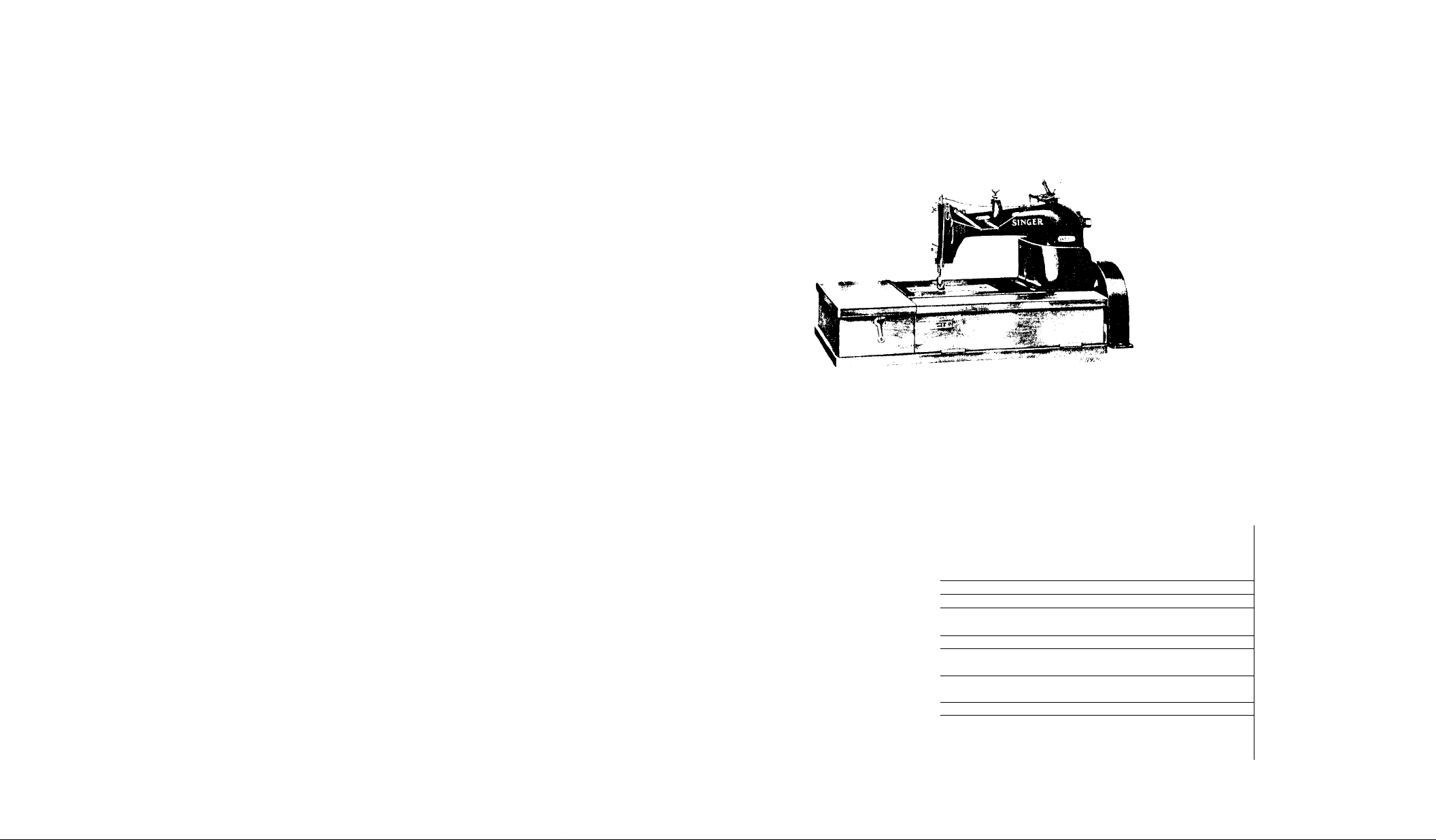
LIST OF PARTS COMPLETE
FOR
MACHINE No. 147-80
FOR LIGHT WEIGHT FABRICS. ONE NEEDLE,
ONE LOOPER. LENGTH OF STITCH 10 TO 25 TO
THE INCH. NEEDLE BAR STROKE I i/g INCHES.
BALL BEARING. SPEED 4300 R. P. M.
No. Plate
*131446
68428
68429
20688
20668
1057AL 20688
50608R 20688
139017 20688 Arm
68350
131309
131305
20695
20696 Arm
20696 Arm
563AL 20696
131319
20695
Arm
upper and lower (solid) with 948J,
15404, two 15405 and four 131022
Arm
Bottom Cover
" " Gasket (cork)...............
tl
" " Screw (4)...................
It
Hole Plug Screw, for access to Crank
Connecting Rod (upper bearing)
Hole Plug Screw Washer
II
Oil Cup, for oiling Arm Rock Shaft
Front Bearing.....................
Oil Cup with 131310, for filling oil
reservoir.........................
Oil Cup Drip Pan with two 563AL
'' " " " Position Screw (2).
II
“ " Oil Pad (braided cotton) for
6835 0............................
Name
......................
__
....
............
...

PARTS FOR MACHINE No. 147-80
No.
131293
131474
Plate
2069h
It
Rock Shaft.
tl
II It
Name
131293 with 1235F, 127838
and 131475.
1309C
131056
68433
68435
131095
20695
20695
20695
20695
20695
Rock Shaft
Arm
II II
"
N II II
II
II n
M II H
Adjusting Screw
" " Washer...
Bushing (back)
“ " Cap..............
" n It Washer
(fibre)... .
446AL
68436
423AL
131343
20695 Arm
20695
20695
20696
Rock Shaft Bushing (back) Set Screw
II
Arm
II II
n It
Rock Shaft
'' (Intel-mediate)...
" “ Set
Crank, back (ball bearing,
solid) with two 50083AL
50083AL
131475
127838
131456
453AL
42365
54969
1235F
131476
20696
Arm
20695 Arm
20695
20695
20695
20695
20695
'*
II
Arm Rock Shaft
Arm
20695 Arm
20696
Rook Shaft
(2)
......
Rock Shaft
n If
II
M H
If If
for oiling
Rock Shaft
for oiling
Rook Shaft
II
Rotary Shaft
Crank (back) Set Screw
Crank (front) with 853AL
" " Pin..............
Flanged Bushing (front)..
" " " Set
Oil Pad (braided cotton)
Back Bearing
Oil Pad (braided cotton)
Intermediate Bearing
Oil Plug Screw
.....................
Note: When No. 131476 Is required for repairs, the
Looper Driving Shaft and Feed Lifting Eccentric
must be returned to the factory to be adjusted
to the new part.
131477
Arm
131484 and 131502.
131366
131478
131479
20696
20696
Arm
II II II II n Qggg
It
t| II II n n II
If
131478 With 131369 and three 205C...
Rotary Shaft Ball Bearing (back)
131526
Arm
Case with Ball Bearings complete,
Nos. 131479, 131480 and two 131366..
131369
20696
Arm
Case Cap.
205C
131370
20696
20696
Arm
Case Cap Screw (3)
Rotary Shaft Ball Bearl
Arm
...
Case Position Stud (3).
Rotary Shaft Ball Bearl
429C
20696
Arm
Case Set Screw
.......
........
.........
..........
...........
...
.........
No.
131480
131366
Plate
20696
20696
131481 20696
1304C 20696
131482
20696
457AL 20696
131457
76 IE
20696
20696
42367 20696
54218
144D
131276
131277
131280
51224W
131278
68448
1057AL
131483
20696
20696
20688
20688
20688
20688
20688
20688
20688
20696
131710
128510
51283AL
20696
20696
131374 20704
68368 20704
131050
725J
131051
131375
131381
725J
131382
131380
lOllF
20704
20704 " " « « " Screw (2)
20704
20704
20704
20704
20704
20704
20704
PARTS FOR MACHINE No. 147-80
Name
Arm Rotary Shaft Ball Bearing (back)
Spacing Collar
....................
Arm Rotary Shaft Ball Bearing (Inter
mediate)
.........................
Arm Rotary Shaft Ball Bearing (inter
mediate) Case
.....................
Arm Rotary Shaft Ball Bearing (Inter
mediate) Case Set Screw
...........
Arm Rotary Shaft Ball Bearing (Inter
mediate) Collar with two 457AL
Arm Rotary Shaft Ball Bearing (Inter
mediate) Collar Set Screw (2)
Arm Rotary Shaft Bushing (front)
.....
......
" " " “ " Set Screw
" " " Front Bearing Oil Pad,
lower (braided cotton)
............
Arm Rotary Shaft Front Bearing Oil Pad,
upper (braided cotton)
Arm Rotary Shaft Screw
............
................
" Side Cover (oil vent)..............
" " " Cap
" " " " Position Pin
" " " " Thumb Screw
...........................
................
.................
Arm Side Cover (oil vent) complete. Nos.
51224W, 131276, 131277 and 131280...
Arm Side Cover Gasket (vlctorlte)
" “ " Screw (4)
.....................
.....
Balance Wheel, 2 In. pulley, with two
51283AL, for round belt
...........
Balance Wheel "v" belt groove, with two
51283AL
Balance Wheel Cover
" " Set Screw (2)
...........................
...................
..................
Cloth Plate...........................
" ” Slide (left)....................
" " " ” Spring
.....................
Cloth Plate Slide (left) complete. Nos.
68368, 131050 and two 725J
Cloth Plate Slide (right)
........
.............
" " " " Spring......................
" " “ " " Screw (2)
Cloth Plate Slide (right) complete. Nos.
131375, 131381 and two 725J
.......
Cloth Plate complete, for Throat Plate
No. 38486, Nos. 131051, 131374 and
131382
............................
Cloth Plate Screw (left) (2)
..........
....

No.
50396F
Plate
20704
131394 20704
389F
50473F.
20704
20704
13147] ), 20696
131484
896AL 20696
1057AL 20696
68460 20706
68461
20706
330D 20706
131395 20706
29234 20706
10БЗЕ 20706
51224W
20706
131729 20702
131730
20702
190J 20702
22436
20702
131731
131197 20702
59343
735AL
134258
134259
20702
20702
20702
20702
68495 20702
134260 20702
68467
20702
207E 20702
131500 20696
131502
896AL 20696
1057AL 20696
68497
134260
20696
20696
54177 20707
131544 20708
131545 20708
PARTS FOR MACHINE No. 147-80
Name
Cloth Plate Screw (right)
'' '' Thread Guard
............
..............
" " " " Screw (lower)..
" " ” и ri (upper)..
Crank Connecting Rod with two each 896AL
and 1057AL
.......................
Crank Connecting Rod 131471 with 131343.
" " " Cap (lower) Screw
(2)
..............................
Crank Connecting Rod Cap (upper) Screw
(2)
Face Plate (lower half)
..............................
..............
" " " " Gasket (cork)...
“ " " " Screw (2)
" " (upper half)
" " « « Position Plate..
It II II II II II
Screw
............................
................
......
Face Plate (upper half) Thumb Screw
Feed Bar
.............................
" " Feed Dog Seat (adjustable) with
460AL
Feed Bar Feed Dog Seat Screw
............................
.........
" ............... '' Washer
.......
Feed Bar with Feed Dog Leveling Device
complete, Nos. 190J, 22436, 68467,
131729, 131730 and two 207E
Feed Bar Hinge Pin (eccentric)
......
.......
" " " " Collar with 735AL
" " " " " Set Screw
" " Slide Block
.................
......
" " " “ 134258 with 68495 and
134260
Feed Bar Slide Block Oil Pad (wick)
...........................
...
" " “ " " " Retainer...
" " Wearing Plate
“ " ” '' Screw (2)
................
.......
Feed Connecting Rod with 1057AL, 68497,
134260 and two 896AL
.............
Feed Connecting Rod 131500 with 54025...
'' " " Cap Screw (2).....
" " " Clamping Screw
" " " on Pad (wick).....
« H H II II *.« .
Retainer....
.....
___
" Dog, 16 teeth (16 teeth to the
Inch) for 38486
..................
Feed Dog,13 teeth (12 teeth to the Inch)
for 46059
........................
Feed Dog,17 teeth (16 teeth to the Inch)
for 46059
........................
..
___
No.
50073J
140275J
460AL
5106lAL
7071
217J
54025
1103C
131240
131732
57234
57235
453AL
453AL
25618
51224W
131133
13113<i
54027
175E
54227
54228
128419
68478
51263D
68479 20698
175E 20698
•68481
Note; When No. 68481 Is required for repairs, the
•68482
948J
68484
131028
PARTS FOR MACHINE No. 147-80
Plate
20707
20707
20702
20696
20696
20696
20696
Feed Dog Screw, when stationary Needle
Guard Is used
Feed Dog Screw, when movable Needle
Guard Is used
Feed Dog Stop Screw...................
” Eccentric Body Set Screw (3)
'' ' Clamping Washer (2)............
" " " " Screw (2)
Feed Eccentric (adjustable) with 1103C,
Name
.....................
.....................
.....
two each 217J,7071 and three 51061AL
20696
20702
Feed Regulating Screw
" Rocking Frame with two 453AL
.................
......
" " " 131240 with 59343,
20702
20702
20702
20702
131197 and 131731
Feed Rocking Frame Hinge Pin
" " n « • gugjjlng (2)
" • . » • «
Screw (2)
.........................
Feed Rocking Frame Hinge Pin Set Screw
.................
..........
(2)...............................
20704
20704
20707
20707
20698
20698
20698
20698
20698
.................
" Thumb Screw.......................
Looper................................
“ 131133 with 229J and 131135
" Carrier with two 175E............
" " Adjusting Screw (2)............
" " Connection.....................
" " “ Shaft........................
" " " "on Pad
...............
......
Guide
(braided cotton)..................
20698
Looper Carrier Connection Shaft Sleeve
(eccentric).......................
20698
Looper Carrier Connection Shaft Sleeve
Cap Screw
Looper Carrier Driver with four 175E
.........................
--
" " " Cap Screw (4).................
20698
" Driving Shaft and Feed Lifting Ec-
centric
...........................
Arm Rotary Shaft must be returned to the factory
to be adjusted to the new part.
Looper Driving Shaft and Feed Lifting
Eccentric 68481 with 54027, 54227,
20696
20698
20698
54228 and 68479
Looper Driving Shaft and Feed Lifting
Eccentric Bracket Screw
Looper Driving Shaft and Feed Lifting
Eccentric Bushing
Looper Driving Shaft and Feed Lifting
Eccentric Bushing Oil Plug
...................
...........
.................
........

10
No. Plate
761E 20696
68497
64 OE
20696
54035 20698
51119J 20698
131135 20707
46105
20707
229J 20707
1120C 20698
68485 20698
68486 20698
43503
20698
443AL 20698
131490
20700
131291 20700
1133AL 20700
64320 20700
1133AL 20700
68488
20700
131491
68489 20700
1520J 20700
131270 20700
861C
20700
853AL 20695
131492 20700
1492E
131316
68123
20700
20702
20702
131315 207 07
54038 20707
176J 20707
2170
857AL
20707
20700
68492 20703
68493 20703
PARTS FOR MACHINE No. 147-80
Name
Looper Driving Shaft and Feed Lifting
Eccentric Bushing Position Screw....
Looper Driving Shaft and Feed Lifting
Eccentric Front Bearing Oil Pad
(wloF)
...........................
Looper Driving Shaft and Feed Lifting
Eccentric Screw
Looper Holder with 1120C
..................
.............
" " Screw.....................
" Needle Guard with 46105
" " " Pin
'' " “ Screw
" Set Screw
.......................
.........
................
..............
” Throw-out Handle with two 443AL..
" “ " Plunger
........
" « « ,. Spring..
" " '' Set Screw (2). ..
Needle Bar (hollow) with 857AL
" " Bushing (lower)
.......
.............
" " " " Set Screw
" " " (upper)
................
" " " " set Screw
" " Connecting Link and Thread
(upper) Controller
...............
Needle Bar Connecting Link and Thread
(upper) Controller 68488 with 68489
and 131492
.......................
Needle Bar Connecting Link Hinge Stud
(hollow)
.........................
Needle Bar Connecting Link Hinge Stud
Nut
..............................
Needle Bar Connecting Link Hinge Stud
Oil Pad (wick)
...................
Needle Bar Connecting Link Hinge Stud
Oil Plug Screw
...................
Needle Bar Connecting Link Hinge Stud
Set Screw
........................
Needle Bar Connecting Stud with 1492E...
" " " " Clamping Screw
" Guard (movable)
" " " Clamp
" " (stationary)
.................
..............
.............
” " " Holder.......
" " " " Screw..
" " Screw
'' Set Screw
....................
......................
Oil Pipe (back of arm) with 68497, for
oiling Feed Rocking Frame Hinge Pin
Front Bearing
Oil Pipe (back of arm) Clamp
....................
.........
___
___
No.
176E
68494
198E
68495
68496
1733
68497
68498
131112
68500
131113
131258
131002
131003
131084
198E
131004
131004
131087
1733
131089
68497
64330
131006
1133AL
38456
1133AL
PARTS FOR MACHINE No. 147-80
Plate
20703 Oil
20703
Pipe (back of arm) Clamp Screw
II
" HU« Connection with
68495 and two 198E, for oiling Feed
Rooking Frame Hinge Pin Back Bearing
20703
Pipe (back of arm) Connection Cap
Oil
Screw (2)
20703
Pipe (back of arm) Connection Oil
Oil
Pad (wick)
20703
20703
20703
20703
Pipe (back of arm) Coupling
oil
Л
" B » « « (brass)
Й
• " ■ * on Pad (wick)...
n
" (front of arm) with 131089 and
two 1733, for oiling Looper Driving
Shaft and Feed Lifting Eccentric
Front Bearing
20703
Pipe (front of arm) with 68497 and
Oil
131003, for oiling Feed Bar Slide
Block.............................
20703
Pipe (front of arm) with 1733,131084
oil
and 131089, for oiling Arm Rotary
Shaft Front Bearing
20703
Pipe (front of arm) with 68497 and
oil
131000, for oiling Feed Connecting
Pipe (front of arm) complete. Nos.
oil
68498 , 68500, 131112 and 131113
20703
Pipe (front of arm) Connection with
oil
two 198E, for oiling Looper Throw-
out Device........................
20703
Pipe (front of arm) Connection with
oil
two 198E, for 131112 and 131113 (2)
20703
Pipe (front of arm) Connection with
oil
two 198E, for 68500
20703
Pipe (front of arm) Connection Cap
oil
Screw (2).........................
20703
20703
20703
20703
Pipe (front of arm) Coupling (cen-
oil
Plpe (front of arm) Coupling (left).
on
M
* “ " " ’ (right)
If
. . . . 'Nut
(brass) (3)....................
20703
Pipe (front of arm) Oil Pad (wick)
on
for 68498 and 68500 ( 2)
20703 on
Pipe (front of arm) Oil Pad (wick)
for 131112 and 131113 (2)
20700
20700
20700
20700
20700
Presser Bar...........................
" " Bushing (lower)
" " ” " Set Screw...
* * " (upper)
" " " " Set Screw...
11
Name
....
.........................
........................
.......
.....................
...............
..
...............
.
..........
.........
...............
.....................

12
No.
Plate
131401 20700
11173
453AL
453AL
131402
68184
20700
20700
20700
20705
20705
161J 20705
802D
131749
20705
20688
131750 20688
131751
20688
1637J 20688
38468
131830
26276
46056
20688
20688
20707
20707
4 6067 20707
46058
20707
190J 20707
51697W
20688
131752 20688
131419
20706
131404 20706
131405 20706
1423J 20706
17UL 20706
131406 20706
217J
20706
131012 20705
69 IF
20705
2102 20705
51570C 20705
50326C
20705
59539
131740 20705
59537 20705
59538
131696
20705
20705
PARTS FOR MACHINE No. 147-80
Name
Presser Bar Lifting Bracket with 453AL..
.
...........
" Guide
..............
" " " " "Set
Screw
............................
Presser Bar Lifting Bracket Set Screw...
" " " Lever
.............
" " " " Extension
" " " " " Screw
(2)
..............................
Presser Bar Lifting Lever Hinge Screw...
Presser Bar Spring
“ " ” (auxiliary)
“ “ " Screw Stud
...................
........
...........
" " " " " Look Nut..
" " " Stud
...............
Presser Bar Spring complete. Nos. 1637J,
5169'7W and 131749 to 131752
Presser Foot Hinge Pin
” " Plate
" " Shank
..............
....................
....................
.....
Presser Foot (hinged) complete. Nos.
26276, 46056 and 46057
Presser Foot Screw
...................
Pressure Regulating Thumb Nut
...........
........
" “ " " Washer....
Slack Thread Regulator
" " " Holder
...............
.........
" " " " Crank with
17UL
.............................
Slack Thread Regulator Holder Crank Cap
Screw
............................
Slack Thread Regulator Holder Crank
Clamping Screw
...................
Slack Thread Regulator Holder Crank Con
necting Link
Slack Thread Regulator Screw
Tension (under thread) Bracket
" « n (2)
“ " " Disc (2)
.....................
.........
.......
........
" " ” Regulating Thumb
Nut
..............................
Tension (under thread) Screw Stud
" " " " " 50326C
with 51570C
Tension (under thread) Spring
......................
........
" " " " Bushing
(large)
..........................
Tension (under thread) Spring Bushing
(small)
..........................
Tension (under thread) Thread Guide
.....
....
..
13
No.
54045
376J
2102
51570C
32572
54988
54046
54047
PARTS FOR MACHINE No. 147-80
Plate
20705
20705
20705
20705
20705
20705
20705
Tension (upper thread)
It II H
H H II
H «It
Ni)t
...........
Tension (upper thread)
Jf M «
n « «
20705
Name
Bracket
" Screw....
Disc (2)
Regulating Thumb
Releasing Disc...
" Pin________
" Shaft..
.........
........
Crank with 624AL..
54048
624AL
68261
131011
.
316C
1547J
20705
20705
20705
20705
20705
20705
Tension (upper thread)
Crank .Link
.....
Tension (upper thread)
Crank Set Screw...
Tension (upper thread)
Spring
..........
Tension (upper thread) Releasing Shaft
Spring Position Plate
Tension (upper thread)
Stop Screw
......
Tension (upper thread)
Releasing Shaft
Releasing Shaft
Releasing Shaft
.............
Releasing Shaft
Releasing Shaft
Stop Screw Nut....
50326C
59539
131741
59537
59538
131696
53225
190J
131407
131408
50438J
1258AL
]31409
54242
190J
131410
134411
131420
20705
20705
20705
20705
20705
20705
20705
20696
20696
20696
20696
20696
20696
20696
20696
20696
20696
Tension (upper thread)
II II <1
with 51570C
Tension (upper thread)
II It II
(large)
.....
.........
Tension (upper thread)
(small)
.........
Tension (upper thread)
Thread (under) Eyelet
It II n
" " Take-up
II « H
II H It
II N II
II H H
If II n
II n «
Thread (under) Take-up Stripper Plate...
n H K
Bracket
.........
Screw Stud
" " 50326C
Spring
Spring Bushing
Thread Guide
(back)
" Screw
with 1258AL
Oil Guard
" " Screw..
Set Screw
Stripper
Thread (under) Take-up Stripper Plate
......
..........
" Bushing
....
..........
.........
.....
.......
......
........
" Clamp...
Bracket 131411 with 32062, 50438J,
54242, 131408 to 131410, 131413,
131421, 131422, two each 207J, 7071,
965D
20696
50470J and four 190J
Thread (under) Take-up Stripper Plate
Bracket Screw
.....................
..............

14
No.
190J
32062
131413
50470J
131421
207J
7071
131422
207J
7071
131493
190J
131494
223J
131495
131496
997J
38486
46059
742F
*15404
15405
PARTS FOR MACHINE No, 147-80
Plate
20696
20696
20696
20696
20696
20696
20696
20696
20696
20696
20706
20706
20706
20706
20706
20706
20706
20707
20708
20707
Thread (under) Take-up Stripper Plate
Screw (3)
Thread (under) Take-up Stripper Washer..
" " '' Thread Guard
(fibre)
Thread (under) Take-up Thread Guard
Screw (2)
Thread (under) Take-up Thread Guide
(left)
Thread (under) Take-up Thread Guide
(left) Screw
Thread (under) Take-up Thread Guide
(left) Screw Washer
Thread (under) Take-up Thread Guide
(right)
Thread (under) Take-up Thread Guide
(right) Screw
Thread (under) Take-up Thread Guide
(right) Screw Washer
Thread (upper) Eyelet
" " " Screw
" ” Take-up with 223J
" " " Clamping Screw...
" " ” " Clamp
tt If If II II
Screw
Throat Plate for 54177
..........
" " Screw (2)
—
Trade Mark
" " Rivet (2)
—
Name
........................
..........................
........................
...........................
.....................
..............
..........................
....................
.............
................
.............
........
" " (auxiliary)
............................
...............
131544 and 131545
.................
...........................
..................
......
.....
MACHINE No. 147-81
FOR MEDIUM WEIGHT FABRICS. ONE NEEDLE,
ONE LOOPER. LENGTH OF STITCH 7 TO 25 TO
THE INCH. NEEDLE BAR STROKE I 7/32 INCHES.
BALL BEARING. SPEED 4000 R. P. M.
NOTE: THIS MACHINE IS THE SAME AS THE 147-80
MACHINE, WITH THE FOLLOWING EXCEPTIONS:
No. Plate Name
131072 20697 Arm Rock Shaft Crank, back (ball bearing,
131485
66459
*131110 20699 Looper Driving Shaft and Feed Lifting
*131111
54036 20701 Needle Bar (hollow) with 857AL, In place
131399
131400 20701 Needle Bar Connecting Stud with 211F and
131025 20709 Slack Thread Controller
54242 20709 " “ " Clamp
190J 20709 II " « . Screw
38484 20709 Thread (upper) Eyelet, In place of
131332 20709 Thread (upper) Take-up
54194 20709 " " " Plate
68164 20709 » . , , Spring
1449J 20709 » » . и » scj-ew
131333 20709 Thread (upper) Take-up complete. Nos.
211F 20701 Thread (upper) Take-up Set Screw
....
Arm Rotary Shaft 131476 with 640E,68459,
----
Crank Connecting Rod 131471 with 131072,
Note: When No. 131110 Is required for repairs, the
Arm Rotary Shaft must be returned to the factory
to be adjusted to the new part.
----
Looper Driving Shaft and Feed Lifting
----
Needle Bar Connecting Link and Thread
solid) with two 50083AL, In place of
131343............................
131111 and 131502, In place of
131477............................
In place of 131484................
Eccentric, In place of 68481
Eccentric 131110 with 54027, 54227,
54228 and 68479, In place of 68482..
of 131490.........................
(upper) Controller 68488 with 68489
and 131400, In place of 131491
1492E, In place of 131492.........
131493............................
1449J, 54194, 68164 and 131332, in
place of 131494
...............
.............
..................
...................
......
....
.....
............
......
........
15

16
FOOT LIFTER PARTS
17
ACCESSORIES
No.
120344
120345
120440
121108
120341
4822
0908
Plate
20691
20691
20691,
20691
20691
20691
20691
Oiler (copper plated) with 120345.
'' Spout, 4 1/2 In. long
Screw Driver (large)............
" " (small)
Tweezers (curved)...............
Wrench for 1547.................
" " 1520
Name
.....
...............
.................
BELT GUARD
No. Plate Name
68222 20633 Belt Guard with two wood screws 1
No. 12
......................
BENCH STAND
No.
79772
126849
27998
126247
126248
41538
60656
Plate
20691
20691
20691
20691
20691
Bench Stand with 27998, two each 41538,
126849, three Wood screws 1 1/4 In.
No. 12, four each 60656, wood screws
1 1/4 In. No. 10 and sixteen wood
screws 5/8 In. No. 7
Flap Hinge with four wood screws 3/4 In.
No. 7
Flap Hook and Eye (brass) with wood
F'lush Bolt
Flush Bolt with Plate complete. Nos.
Hinge (4)
............................
screw 1/2 In. No. 5
" “ Plate
126247, 126248 and four brass wood
screws 5/8 In. No. 4
............................
Name
.............
..............
..........................
......................
.............
In.
No. Plate Name
4879 20633 Chain Connecting Link
56864 20691 " Hook (large)
56865 20691 " " (small).....................
126249 20633 Treadle
4882 20633 “ Shaft
126250 20633 " Spring
150451 20633 " Stand
150452 20633 Treadle complete. Nos. 4879,4882,126249,
.................................
126250, 150451 and two wood screws 1
In. No. 16 F.H....................
...................
.....................
.........................
........................
.........................
KNEE LIFTER PARTS
No.
37563
56864
56865
2763
12242
6335 20633
6336
2766
356C 20633
2767 20633
356C 20633
6337 20633
7125
35 6C 20633
356C 20633
2770 20633
356C 20633
23767 20633
Plate
20691
20691
20633
20633
20633
20633
Chain, length 15 In., with 56864 and
56865.............................
Chain Hook (large)....................
" " (small).....................
Rock Shaft............................
" " Hanger with two wood screws 1
In. No. 10 (2)
Rock Shaft Knee Arm
Rock Shaft Knee Arm complete. Nos. 2766,
2767 and 6335
Rock Shaft Knee Arm Hub with 356C
Rock Shaft complete. Nos. 2763, 2770,
" n n « Screw
“ " Plate with 356C
" " " Set Screw
" Lifting Bracket with two 356C
“ " " Hook.........
" " " ” Set Screw
'' " “ Set Screw
" Stop Dog with 356C..........
” " " Set Screw
6336 , 6337 , 7125 and two 12242
Name
...................
...................
.....................
.....
......
........
.........
___
..........
..
FOOT LIFTER PARTS
No. Plate Name
6439
----
Chain, 36 In. to 46 In., with 56864 and
Note: When ordering No. 6439, state length required.
56865
............................
MACHINE BASE
No. Plate Name
131263 21038 Machine Base
54477 21038 “ " Screw Stud, to fasten base
to table (3)......................
131205 21038 Machine Base Screw Stud, to position Ma
chine on base (4)
..........................
 Loading...