

Sinfonia Technology C10 Series, C10-1VFEF, C10-3VFEF, C10-5VFEF Instruction Manual
Directive
DirectiveDirective
Directive
and confirms with the CE Marking
and confirms with the CE Markingand confirms with the CE Marking
and confirms with the CE Marking
....
CONTROLLER
CONTROLLER
Ins
Instruction Manual
truction Manual
InsIns
truction Manual truction Manual
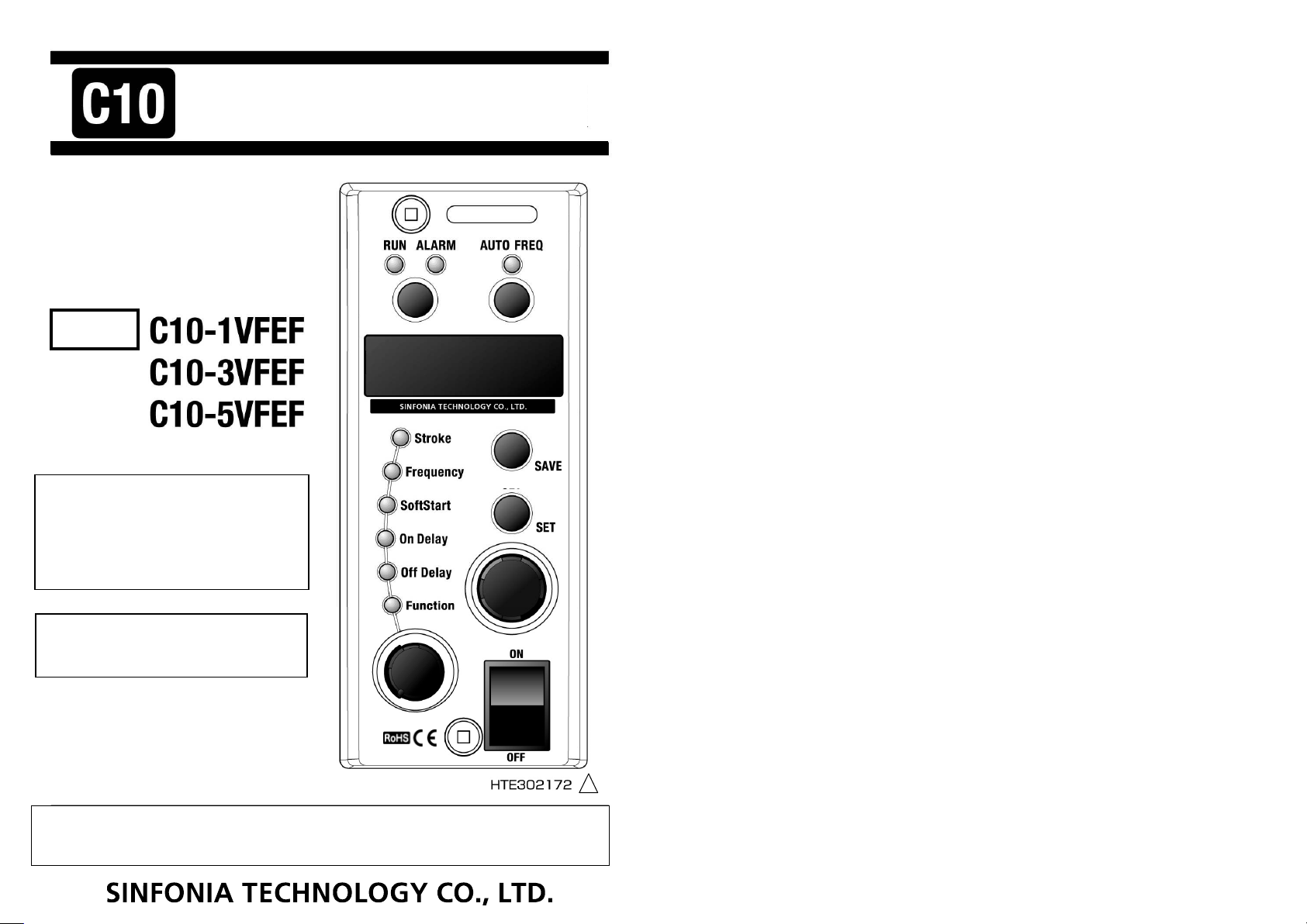
Model
This instruction ma
This instruction manual applies to
This instruction maThis instruction ma
C10
C10----controller
C10C10
version 6
version 6 and later.
version 6version 6
Please check the program version of your
Please check the program version of your
Please check the program version of your Please check the program version of your
C10
C10----controller
C10C10
The controller which is installed the program
The controller which is installed the program
The controller which is installed the program The controller which is installed the program
version
version 5555 and later co
version version
Instructions
Instructions”””” thoroughly to use it in the right way. Please keep it on file for further reference.
InstructionsInstructions
controller whic
controllercontroller
controller on the version information.
controllercontroller
BBBBefore use
efore use
efore useefore use
which installs the
h installs the program
whicwhic
and later.
and later.and later.
and later corresponds
and later coand later co
h installs theh installs the
on the version information.
on the version information.on the version information.
rresponds to
rrespondsrresponds
C10
C10----controller
controller
C10C10
controllercontroller
thoroughly to use it in the right way. Please keep it on file for further reference.
thoroughly to use it in the right way. Please keep it on file for further reference.thoroughly to use it in the right way. Please keep it on file for further reference.
CONTROLLERCONTROLLER
nual applies to
nual applies to nual applies to
program
program program
to the
the RoHS
RoHS
to to
the the
RoHS RoHS
, please read this
, please read this ““““Instruction Manual
, please read this , please read this
Instruction Manual”””” including
Instruction ManualInstruction Manual
including ““““Safety
including including
HTE302172 0/38
Safety
Safety Safety
6666
HTE302172 0/46
5
6
Thank you for buying your C10-Series controller. Before use C10-controller,
Introduction
IntroductionIntroduction
Introduction
Safety Instructions
Safety InstructionsSafety Instructions
Safety Instructions
please read this “Instruction Manual”, including “Safety Instructions”, thoroughly to use
C10-controller safely and in the right way. Please keep it on file for further reference and/or
maintenance. Please hand this manual to the operator of the partsfeeder.
Contents
Contents
ContentsContents
Introduction…………………………………………………………………… 1
Safety Instructions ………………………………………………………… 2
Wiring Connections ………………………………………………………… 5
How to operate the Control Panel ……………………………………… 7
・
Name and Function of the Buttons, Lamps and Dials on the Control Panel …… 7
・
How to Run and Stop the Partsfeeder …… 8
・
Alarm by blinking “RUN” lamp …… 8
・
Basic Setting up Procedure …… 9
・
How to adjust the Function Set Value …… 11
Initial Setting ……………………………………………………………… 13
・
Preparation for operation …… 13
・
How to adjust the Drive Frequency Output Range …… 14
・
How to adjust the Stroke on the Auto-tuning Mode …… 16
・
How to set the Stroke on the Constant Voltage Mode …… 18
・
How to adjust the Stroke on the Constant Stroke Mode …… 20
・
Scaling of the stroke …… 22
Additional Function…………………………………………………………………24
・
Setting up for Key Lock function …… 24
・
Setting On and Off Delay Time …… 24
・
Setting of Soft Start Ramp-up Time …… 24
・
Connection of Overflow and Stroke sensors …… 25
How to use External Signal Terminals ………………………………………… 29
・
External Operation Signal Terminals “P1” and “P2” …… 29
・
Operation Synchronous Signal Terminals “Q1” and “Q2”.and “AUX .OUT”…… 30
・
Speed Change /Control by 4-20mA Current
/Two-Rate-of-Feed control by External Rheostats …… 30
Conformity with CE Marking ………………………………………………… 36
Trouble shooting …………………………………………………………………… 39
Function Table ……………………………………………………………………… 40
How to Initialize the Settings ………………………………………………… 41
Outline Dimensions…………………………………………………………………… 42
Accessory List ……………………………………………………………………… 43
Specifications ……………………………………………………………………… 44
Guarantee …………………………………………………………………………… 45
Sales offices …………………………………………………………………………… 46
- Please read this article thoroughly without fail -
Before use C10-controller, please read this “Safety Instructions” carefully to use C10-controller in
the right way.
Use of this C10-controller involves electrical current. There is potential hazard of electric shock to
the operator. Failure to follow these instructions may result serious personal injury or property damage.
Safety Instructions are classified into
Safety Instructions are classified into ““““Danger
Safety Instructions are classified into Safety Instructions are classified into
This label shows an immediate danger.
Misuse of C10-controller and/or risky action of any person should cause the
person serious and/or fatal injury and/or severe damage to your property.
This label shows an indirect danger.
Misuse of the partsfeeder and/or risky action of any person should cause
the person injury and/or damage to your property.
This label shows an indirect danger.
Misuse of C10-controller and/or risky action of any person might cause the
person injury and/or damage to your property.
This label shows the manufacturer’s strong recommendation to use the
partsfeeder properly.
Misuse of C10-controller and/or risky action of any person may not cause
the person injury and/or damage of your property.
Danger
Danger
DangerDanger
Warning
Warning
WarningWarning
Caution
Caution
CautionCaution
Request
Request
RequestRequest
Danger””””,
DangerDanger
, ““““Warning
Warning””””,
, ,
WarningWarning
, ““““Caution
Caution”””” and
, ,
CautionCaution
and ““““Request
Request””””....
and and
RequestRequest
■Please keep this “Instruction Manual” on file for further reference giving easy access
to the operator.
■The partsfeeder that is sold or rented to the other must keep this “Instruction Manual”
on it highly visible.
They must use the partsfeeder in the right way.
■Not all danger should be covered by the “Instruction Manual”. Please read the Instruction
Manual and act on the principle of Safety First.
HTE302172 1/46
5
6
HTE302172 2/46
5
6
Warning
WarningWarning
Warning
Danger
DangerDanger
Danger
Safety Instructions
Safety Instructions
Safety InstructionsSafety Instructions
Don’t apply C10-controller to a piezo-electric type partsfeeder.
Don’t use C10-controller where inflammable material exists. It has not an
explosion-proof structure.
You should fix the controller firmly on the rigid structure. Otherwise the operator
might be injured by falling down and/or abnormal operation of it.
Don’t sprinkle C10-controller with water and/or submerge it in water, or cause the
operator injury and/or get an electric shock.
Before performing any maintenance work, such as opening cover, wiring, replacing fuse
and etc., the electrical supply must be disconnected at the safety disconnect switch.
The electrical circuit inside involves high voltage and the operator should get an
electric shock.
The electrical power supply to C10-controller must be made through a customer-supplied
safety disconnect switch mounted next to C10-controller.
Operate C10-controller within the specified range in the contracted specifications,
or it causes it malfunction, damage and/or shorter life time.
Don’t get on and/or put a thing on the controller, or it results injury by fall, and/or
damage and/or malfunction of it.
Don’t bruise cords and/or leads. Bending by force, pulling, winding and/or clamping
them cause fire and/or getting an electric shock by leakage and/or mal-conduction,
and/or abnormal operation.
Wire C10-controller correctly consulting the “Instruction Manual”. Faulty wiring
causes damage and/or abnormal operation of it.
Before supply C10-controller electrical power, check the wiring.
C10-controller must be grounded properly without fail. Don’t operate it without
grounding.
-Continued-
Caution
Please reserve maintenance space around C10-controller and partsfeeder for daily check
and maintenance.
Don’t install C10-controller dusty area. It has not dust tight structure.
Please lift C10-controller with its body and/or mounting base. Don’t lift it with a
cable.
The output frequency range must match that of the partsfeeder or linear feeder drive
unit. Mismatch causes burnout of the coil of the drive.
Don’t supply C10-controller with electric power through a PWM type inverter, or it
must break C10-controller.
Don’t run and stop C10-controller frequently. To run and stop it every few minutes
and power supply through an electromagnetic contactor mounted on the power supply make
inner electronic parts deteriorate severely. External operation signal enables it to
run and stop frequently.
Don’t provide any switch gear on the output line between C10-controller and the drive
unit to run and stop the drive, or C10-controller must be break.
Don’t arc weld on the bowl, chute and trough while C10-controller and the drive unit
are wired, or earth leakage through C10-controller must break it.
When C10-controller might be used in circumstance and/or conditions that are out of
the supposition of this “Instruction Manual”, and/or use of it might threaten people’s
life and property in danger, consider people’s safety and act on the principle of Safety
First by the margin of the rating and performance.
When C10-controller might be out of order or become useless, scrap it as an industrial
waste subject to local regulation.
C10-controller should be installed on a rigid frame in such location as vibration-free,
no heat transfer, dry and no condensation, and not frozen.
Before connect or disconnect a connector, the electrical power supply must be
disconnected at the safety disconnect switch.
Don’t force a connector, or it causes getting an electric shock by leakage and/or
mal-conduction, damage and/or abnormal operation.
Caution
CautionCaution
Request
Request
RequestRequest
HTE302172 3/46
5
6
HTE302172 4/46
5
6
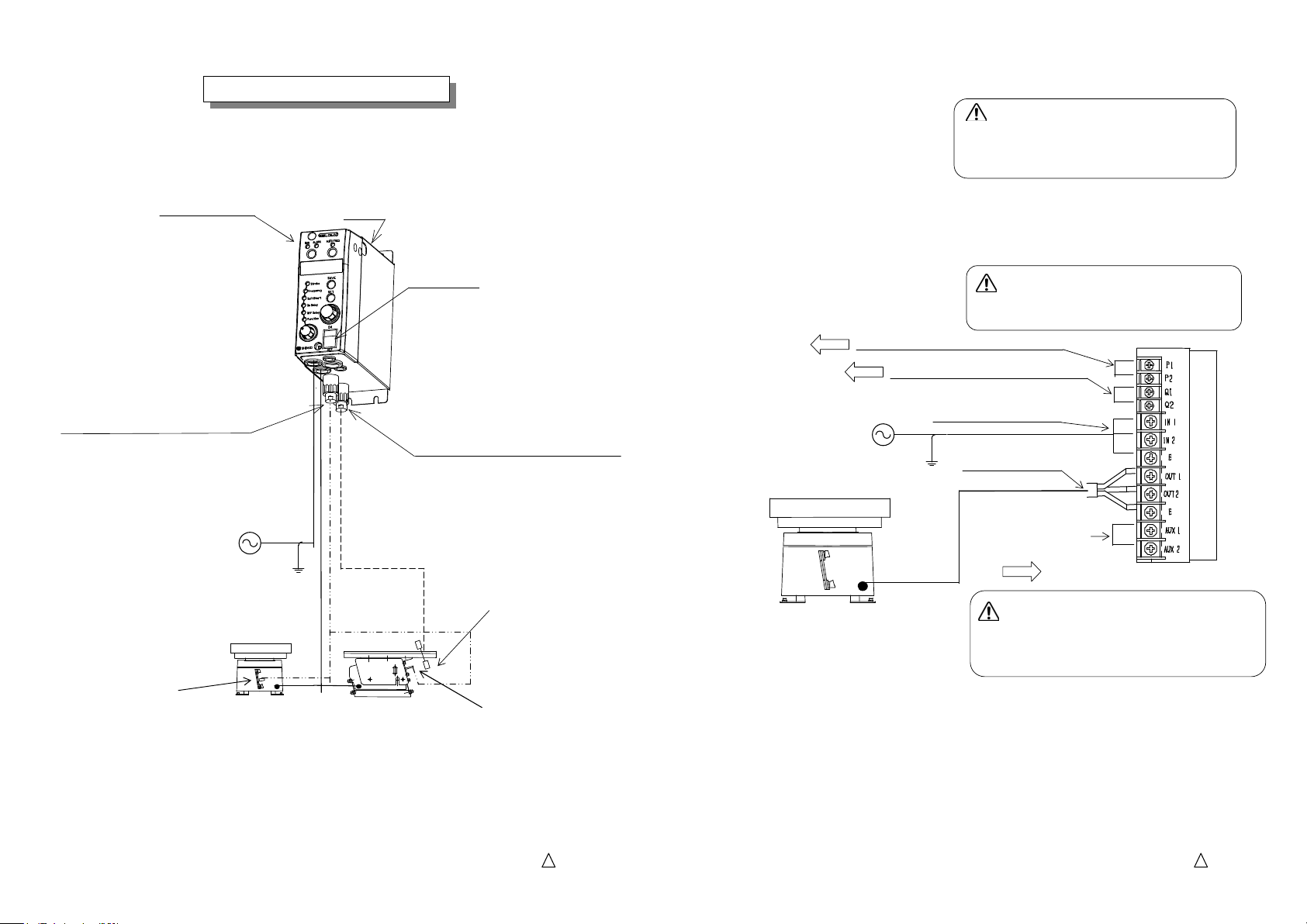
Case
Power Switch
Wire the controller and a partsfeeder or a linear feeder.
Control Panel
Plug and Socket for Stroke Sensor
Input power is AC200 ~ 230V(200V
system), or 100~120V(100V system).
Output voltage is determined
automatically 190V at 200V system
and 95V at 100V system.
Stroke Sensor
Partsfeeder
Note: See page 25 to 28 to use the Stroke sensor and Overflow sensor.
Wiring Connections
Wiring Connections
Wiring ConnectionsWiring Connections
Linear Feeder
Plug and Socket for Overflow Sensor
Overflow Sensor
Stroke Sensor
① Remove the control panel
Danger
Danger
::::
DangerDanger
Before remove the control panel,
disconnect and lock out the power supply at
the safety disconnect switch.
② Connect power supply cable and the output cable for load. Connect the stroke sensor.
Wire each cable or lead on the terminals through rubber bushings respectively.
Power supply cable to terminals “IN1”, “IN2” and “E”
Output cable to terminals “OUT1”, “OUT2” and “E”
See page 29
See page 29
External Operation Signal Terminals
Operation Output Signal Terminals
Warning
Warning
WarningWarning
Connect the ground line to terminal “E”
without fail
Power supply Terminals
Ground Line
Output Terminals
No service is available
See page 29
③ Close the control panel
Danger
Danger
::::
DangerDanger
The control panel must be closed and secured
while C10-controller is in operation. Or else
the operator should get an electric shock.
Note
Note: If any noise from the controller disturbs any other device, the controller
NoteNote
should provide suitable noise suppression parts on it at your own expense.
Please consult “Conformity with CE Marking” on page 36 for selection and
installation of the parts.
HTE302172 5/46
5
6
HTE302172 6/46
5
6
How to operate the Control Pane
How to operate the Control PaneHow to operate the Control Pane
How to operate the Control Pane
l
How to Run and Stop the Partsfeeder
How to Run and Stop the PartsfeederHow to Run and Stop the Partsfeeder
How to Run and Stop the Partsfeeder
Alarm by blinking
Alarm by blinking Alarm by blinking
Alarm by blinking
““““
RUN
RUNRUN
RUN
””””
lamp
lamplamp
lamp
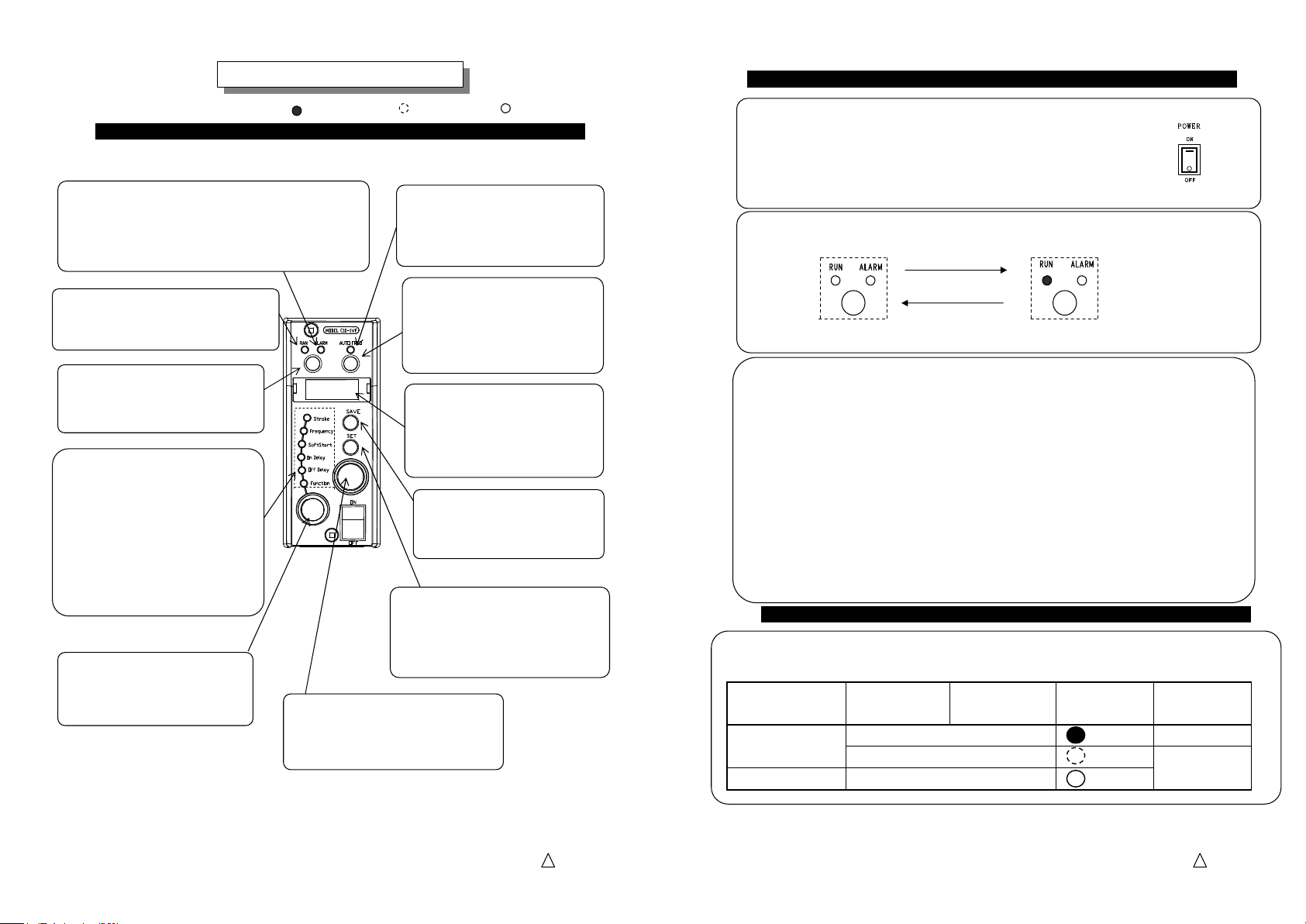
Name and Function of the Buttons, Lamps and Dials on the Control Panel
Name and Function of the Buttons, Lamps and Dials on the Control Panel
Name and Function of the Buttons, Lamps and Dials on the Control PanelName and Function of the Buttons, Lamps and Dials on the Control Panel
: Turning on
“ALARM
ALARM” Lamp
ALARMALARM
The lamp is turned on at two occasions:
a. On the “Constant Stroke” and “Auto-tuning” modes the
output voltage of C10-controller has saturated and it can
not chase the setting point of the stroke.
b. Any error has issued a warning.
“RUN
RUN” Lamp
RUNRUN
The lamp is turned on while the
partsfeeder is running.
RUN/STOP
RUN/STOP” Button
RUN/STOPRUN/STOP
Run and stop the partsfeeder
manually.
“SELECTION
SELECTION” Lamps
SELECTIONSELECTION
The lamp shows what kind of data is
appearing in the “DISPLAY”.
Stroke: Output voltage by percentage
Frequency: Output frequency
Soft Start: Rump-up time of soft start
On Delay: On delay time
Off Delay: Off delay time
Function: Name of Function
“SELECTION DIAL
SELECTION DIAL”
SELECTION DIALSELECTION DIAL
The dial selects what is
indicated in the Display.
“SETTING ENCODER
SETTING ENCODER”
SETTING ENCODERSETTING ENCODER
The encoder alters a numeral in the
blinking digit on the display.
: Blinking
“AUTO FREQ
AUTO FREQ” Lamp
AUTO FREQAUTO FREQ
: Turning off
The lamp is turned on the
auto-tuning mode and flickers at
auto-tuning.
“AUTOFREQ
AUTOFREQ” Button
AUTOFREQAUTOFREQ
This button selects the mode to
enable or disable auto-tuning by
pushing more than three seconds.
“DISPLAY
DISPLAY”
DISPLAYDISPLAY
Data such as output voltage by
percentage representing the stroke,
drive frequency, all settings and
error codes is shown on the display.
“SAVE
SAVE” Button
SAVESAVE
Push to store the data having been
set.
“SET
SET” Button
SETSET
The button changes the mode from
“Indication” to “Adjust ”. On the
“Adjust” mode of Stroke and Frequency,
it changes a digit that is adjusted.
1. Turn the power switch on.
Then directly the controller is running.
Note: If the function code “rS” for Run/Stop by the panel is set
to “0”the controller is operated by “RUN/STOP” button.
2. “RUN/STOP” button, when it is pushed, runs and stops the partsfeeder in turn.
Turning off
Stopping
Push
Push
Turning on
Running
If RUN lamp is not turned on or the partsfeeder does not run even if the RUN lamp is
turned on please check the following items.
When the Run lamp is blinking see the next articles.
a. Estimated cause: The output voltage has been set for “0”.
Remedy: Set the output voltage.
b. Estimated cause: The output drive frequency of C10-controller is off the resonance
frequency of the partsfeeder.
Remedy: Adjust it near to the resonance frequency up to get enough stroke.
c. Estimated cause: C10-controller stops by “Error”.
Remedy: Resolve the error indicated by “ERROR CODE”. See page 40.
When “RUN” lamp blinks the external operation signal on the terminal “P1” and “P2” or Overflow
sensor is set for stop even if “Run/Stop by Panel” is set for running.
RUN/STOP
Button
Setting for running
Setting for stopping
External operation
signal “P1” and “P2”
Overflow sensor
Set for running
Set for stopping
Unrelated
“RUN” lamp
Turning on
Blinking
Turning off
Operation
Running
Stopping
HTE302172 7/46
5
6
HTE302172 8/46
5
6
How to operate the
How to operate the How to operate the
How to operate the
Control Pane
Control PaneControl Pane
Control Pane
l
New data is not stored
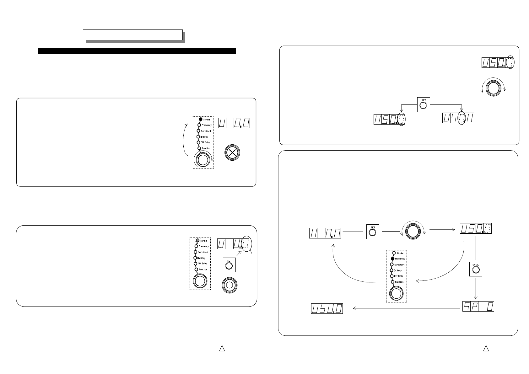
Basic Setting up Procedure
Basic Setting up Procedure
Basic Setting up ProcedureBasic Setting up Procedure
Basic setting up procedure is described here illustrating setting up of the Stroke. The
same procedure is applied for setting up of Frequency, Soft Start Ramp-up time, On-delay
and Off-delay time.
1. Select “Stroke” with the Selection Dial turning on “Stroke” lamp.
Dialing the selection dial turns on selected lamp
Turning on
in the Selection Lamp and the set value of the selected
function appears on the display.
Note: “Stroke” represents percentage of the output voltage
or amplitude per the maximum.
Note: The first letter “U” of the data appeared on the display
Dial
shows “setting by output voltage” and “A” shows
“setting by amplitude”.
Selection Dial
2. Push “Set” button to change the mode from “Indication”
Blinking
To “Adjust”.
It enables alteration of the data appeared on the display
and the lowest digit blinks for alteration.
-Continued-
“Stroke” data appears.
Setting Encoder
“Stroke” data appears.
Push Button
Setting Encoder: Enable
: Disable
Blinking
3. Dial the setting encoder up to appear a desirable setting value on the display.
The“Setting of Stroke”must be set within the maximum stroke of the drive unit.
The digit blinking is changeable with the dial.
Note: On setting “Stroke” and “Frequency” push
the Setting button to shift the digit blinking.
Digit altered
Push button
Dial
Setting Encoder
: Enable
4. Push “Save” button to store the data having been set.
After stored the data the selection lamp stops blinking and is turned on continuously.
The alteration of the setting becomes effective by the procedure 3.
However without “Save” action, turning the power switch off or dialing the setting dial to set
another data cancels the procedure 3. and the data stored is not renewed.
Dial
Push button
Setting Encoder
Dial the Selection Dial
Push button
Select another function
New data is stored.
Note: Function code “SP-0” means Speed Change “No. 0”.
As for Speed Change see the article “External Operation Signal”.
Storing
HTE302172 9/46
5
6
HTE302172 10/46
5
6
How to operate the Control Pane
How to operate the Control Panel
How to operate the Control PaneHow to operate the Control Pane
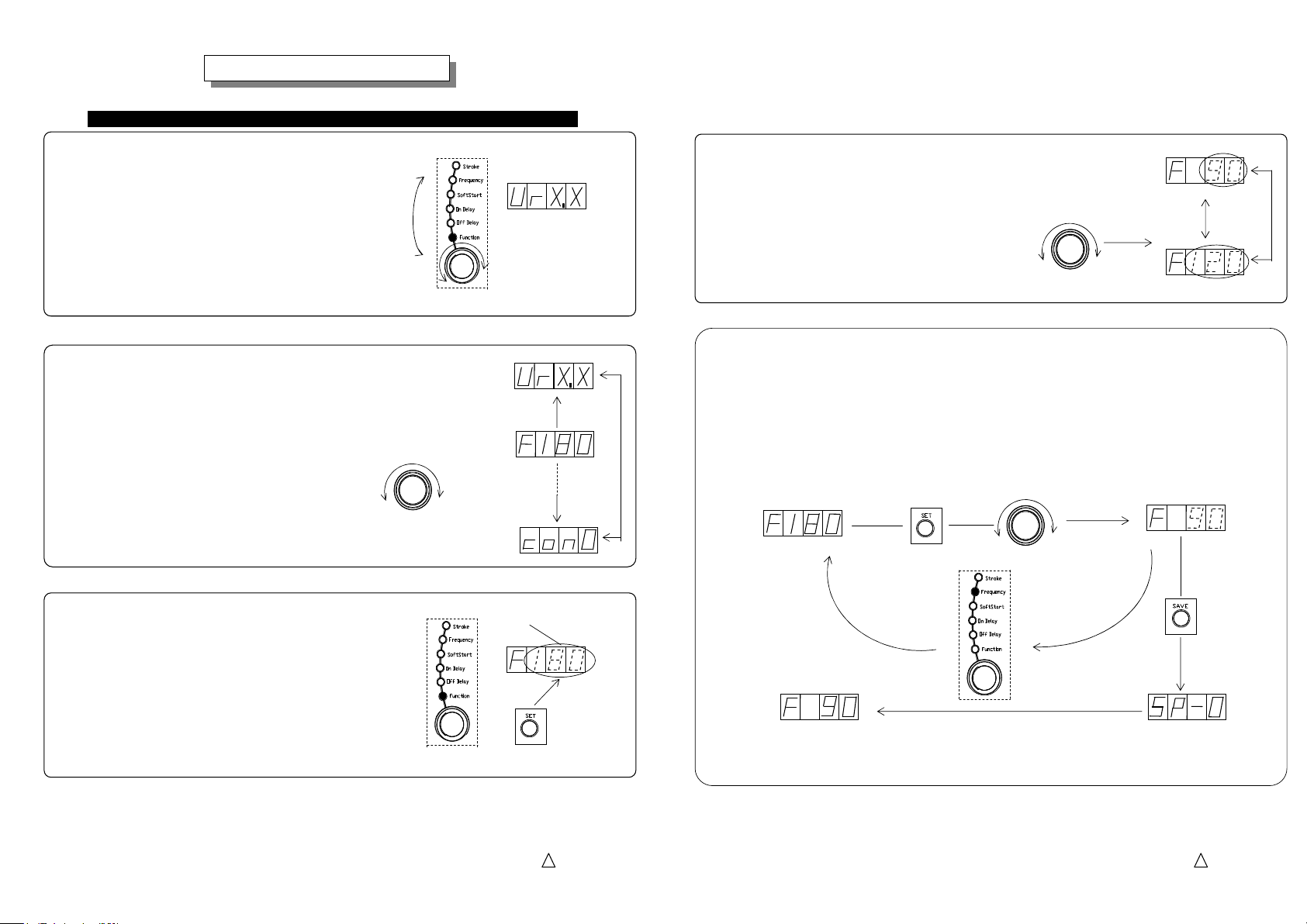
How to adjust the Function Set Valu
How to adjust the Function Set Valueeee
1. Dial the selection dial and select the function turning on “Function” lamp.
How to adjust the Function Set ValuHow to adjust the Function Set Valu
Turning on
Selection Dial
-Continued-
Function data appears.
Dial
2. Dial setting encoder and select the function code altered.
Note: See page 39 for Function Codes and Functions.
Dial
Setting Encoder
3. Push “Set” button to change the mode from
“Indication” to “Adjust”.
It enables alteration of the data appeared on the display
and the lowest digit blinks for alteration.
Note: On the Error Code and Version Information,
“Adjust” mode can not be selected.
Alteration enable
Push button
4. Dial the setting encoder up to appear a desirable setting value on the display.
The digit blinking is changeable by the dial.
The digit blinking is alterable with the encoder.
Please set a proper value on it.
Dial
Setting Encoder
5. Push “Save” button to store the data having been set.
After stored the data the selection lamp stops blinking and is turned on continuously.
The alteration of the setting becomes effective by the procedure 4.
However without “Save” action, turning the power switch off or dialing the setting dial to set
another data cancels the procedure 4. and the data stored is not renewed.
Dial
Blinking
Select another function
New data is not stored
New data is stored
Push button
Setting Encoder
Dial the Selection Dial
Push button
Storing
Note: Function code “SP-0” means Speed Change “No. 0”. As for “Speed
Change” see the article “External Operation Signal”.
HTE302172 11/46
5
6
HTE302172 12/46
5
6
Low frequency
←→
High frequency
Initial Setting
How to adjust the Drive Frequency Output Range
How to adjust the Drive Frequency Output RangeHow to adjust the Drive Frequency Output Range
How to adjust the Drive Frequency Output Range
Initial Setting
Initial SettingInitial Setting
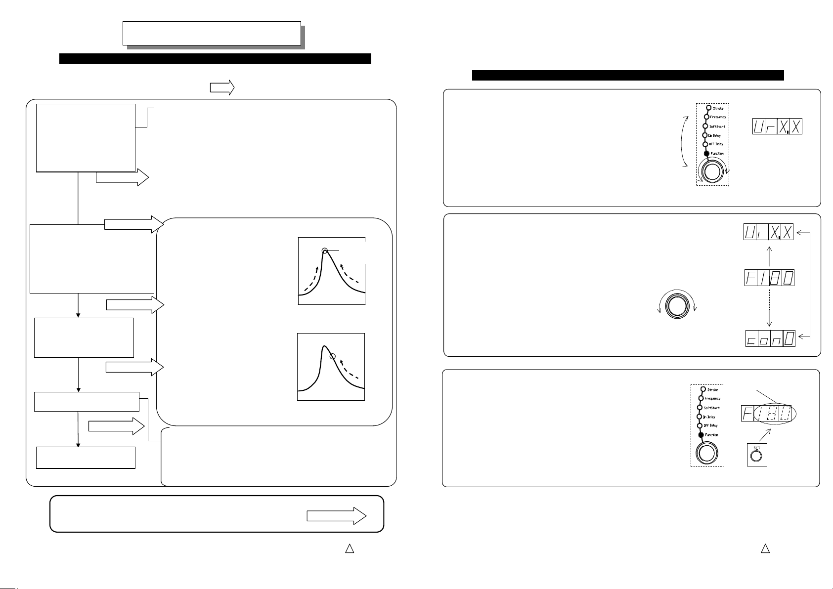
Preparation for operation
Preparation for operation
Preparation for operationPreparation for operation
The preparation for operation is described here. Please follow each setting and see the
detail on the page in the hollow arrow .
1)
1)
Initial Setting
Initial Setting
1)1)
Initial SettingInitial Setting
Set the drive frequency
output range according to
your partsfeeder and
linear feeder.
See page 14
2)
2)
Setting of Stroke
Setting of Stroke
2)2)
Setting of StrokeSetting of Stroke
Set the stroke of the partsfeeder
and linear feeder so smooth that
work pieces are discharging on
the track.
See page 16
See page 20
3)
3)
Setting the maximum
Setting the maximum
3)3)
Setting the maximum Setting the maximum
stroke and Scaling of it.
stroke and Scaling of it.
stroke and Scaling of it.stroke and Scaling of it.
See page 18
4)
4)
Additional Function
Additional Function
4)4)
Additional FunctionAdditional Function
See page 24
5)
5)
Everyday operation
Everyday operation
5)5)
Everyday operationEveryday operation
☆ Output Frequency Range
Select the drive frequency range according to your
partsfeeder and linear feeder.
・45 to 90Hz (Half-wave Drive Unit: ER series)
・90 to 180Hz(Full-wave Drive Unit: EA series)
・180 to 360Hz(High-frequency Drive Unit: series)
・65 to 120Hz(Moderate-Frequency LFB/LFG Series)
☆☆☆☆Operation mode
Operation mode
Operation modeOperation mode
It is depend on using a stroke sensor or not.
Auto-tuning mode “AUTO FREQ”:
Using a stroke sensor
The drive frequency chases the
resonant frequency of the
drive unit automatically.
The stroke is set manually.
Constant stroke control at the
set point
Constant Stroke mode
Using a stroke sensor
The drive frequency and stroke
are set manually.
Constant stroke control at the
set point
Constant Output Voltage mode
Using no stroke sensor
The drive frequency and stroke
are set manually
Constant output voltage
control
Auto-tuning control image
Automatic
Stroke→
Constant Stroke & Voltage
Stroke→
Low frequency
←→
High frequency
・ Setting of Soft start ramp-up time
・ Setting of On delay and Off delay time for Overflow
control
・ Speed change with an external signal and etc.
Any trouble arises during the adjustment please initialize the
setting and restart the adjustment from the beginning.
See page 41
Stay on the
resonant
1. Dial the selection dial and select the “Function” turning “Function” lamp on.
Turning on
Selection Dial
Function data appears.
Dial
2. Dial the setting encoder up to appear code “F”,
Output Frequency Range, on the display.
Dial
Setting Encoder
3. Push “Set” button to change the mode from
“Indication” to “Adjust”.
Alteration enable
Blinkin
Push button
HTE302172 13/46
5
6
HTE302172 14/46
5
6
 Loading...