


SINEAX A 210/A 220
Multifunctional Power Monitor
SINEAX A 210/A 220
Multifunctional Power Monitor
63 measured quantities
8 energy meters
5 average power values P, Q, S each
Application
The A 210/A 220 power measuring instrument is suitable for control panel mounting and measures all the important measurands in 3-phase and single-phase systems.
It displays the measurands with a high contrast 14 mm high LED display. The instrument is also suitable for measurements in high and middle voltage systems because of the freely programmable factors for the current and voltage transformers.
It replaces a large number of analog instruments and delivers highaccuracy values.
The basic execution is an instrument with 2 S0-outputs, which can be programmed as pulse or limit outputs. An extension module extends the functionality and flexibility and supports programming and communication via an RS 232/485 (selectable) interface. It supports data communication with a control system via MODBUS RTU and it can be added without making changes to the basic instrument. Memory and a digital input allow the monitoring and recording of average power values for a minimum of 83 days at 15 min intervals. This function enables the load profile to be determined. Alternatively, the digital input can be used to switch between the high and low tariffs.
Features
●Measurement of current, voltage, active, reactive and apparent power, active and reactive energy, neutral conductor current, power factor and frequency
●4 meters for active power: Incoming/outgoing with high/low tariff
●4 meters for reactive power: Inductive/capacitive with high/low tariff
●5 values each for active, reactive and apparent power averages with programmable interval times
●Two S0-outputs for pulse or limit values
● Dimensions: |
SINEAX A 210: 96 x |
96 x 46 mm |
|
SINEAX A 220: 144 x |
144 x 46 mm |
●Programmable conversion factors
●Flexible power supply with an AC/DC wide-range power supply unit
●Electrically isolated current inputs (1 A or 5 A)
●Upgradeable extension module: RS 232/485 interface (MODBUS RTU), load profile memory, HT/LT switchover, or synchronizing input
●Accurate measured values for U, I ≤ 0.5%, F ≤ 0.02 Hz, others 1%
●Storage of minimum and maximum values
●Measurements in single-phase systems, 3-wire and 4-wire systems in 4 quadrant operation
Benefits
●High functionality (63 measurand values) in a compact form (depth 46 mm)
●Therefore low costs for purchase, engineering and installation
●Safe 3-way galvanic isolation between all circuits and between the 3 current inputs
●Large LED display that can be read from a distance, especially suitable for badly lit rooms
●Upgradeable extension module allows data storage and communication
●Robust front (IP 66) for tough industrial applications
●Storage of all counter values, the min./max. values, the display mode and the programmed data on failure of the power supply
Version |
Order No. |
|
|
A 210 |
A 220 |
|
|
|
500 V / 5 A, power supply 85 to 253 V AC/DC |
149 783 |
152 546 |
|
|
|
500 V / 5 A, power supply 20 to 70 V AC/DC |
150 300 |
152 554 |
|
|
|
500 V / 5 A, power supply 85 to 253 V AC/DC, |
150 318 |
152 562 |
with test certificate |
|
|
|
|
|
500 V / 5 A, power supply 20 to 70 V AC/DC, |
150 326 |
152 570 |
with test certificate |
|
|
|
|
|
500 V / 1 A, power supply 85 to 253 V AC/DC |
152 447 |
152 588 |
|
|
|
500 V / 1 A, power supply 20 to 70 V AC/DC |
152 702 |
152 736 |
|
|
|
500 V / 1 A, power supply 85 to 253 V AC/DC, |
152 710 |
152 752 |
with test certificate |
|
|
|
|
|
500 V / 1 A, power supply 20 to 70 V AC/DC, |
152 728 |
152 744 |
with test certificate |
|
|
|
|
|
Camille Bauer |
Data Sheet A 210/A 220 Le – 08.04 |
1 |

SINEAX A 210/A 220
Multifunctional Power Monitor
Function
The instrument measures the currents I1, I2, I3 and the voltages U1, U2, U3, the frequency, and the phase angles between the individual currents and voltages. All the other measurands are calculated from these. The measurements are made internally via integrated current transformers. Therefore it is possible to make direct connections without an external transformer.
Each input is sampled 32 times per cycle. This allows measurements to be made including up to the 15th harmonic.
The calculation of the measurands is made in accordance with DIN 40 110 part 1 and part 2, however in 4-quadrant operation.
 ind.
ind.
 cap.
cap.
 ind.
ind.
 cap.
cap.
|
|
P |
|
Q |
|
|
|
|
|
–180 |
–90 |
0 |
90 |
180 ϕ |
 outgoing
 incoming
 outgoing
In the figures at this data sheet only SINEAX A 210 is shown. Display and operating are identical with the A 220.
|
3 |
|
5 |
9 |
7 |
|
L1 |
|
|
|
|
|
|
|
|
|
|
1 |
L2 |
|
4 |
S0 + |
|
L3 |
|
|
|||
|
|
|
|||
|
|
|
~ |
S0 1 |
|
|
N |
|
|
|
|
|
|
~ |
|
|
|
|
4 |
P |
S0 2 |
|
|
|
|
|
|||
|
I1+ |
|
|
|
|
|
I1- |
|
EEPROM |
|
|
2 |
I2+ |
|
|
|
|
I2- |
|
|
P |
8 |
|
|
I3+ |
|
|
||
|
I3- |
|
|
Power |
|
|
|
|
|
supply |
|
|
|
6 |
|
|
1: Voltage inputs |
|
|
|
|
|
2: Current inputs |
|
|
|
|
Bus interface/RS 232 |
3: Protection impedances |
|
|
|
|
4: Electrical insulation |
|
|
|
10 |
|
|
5: Microprocessor |
|
|
|
Synchronizing input/ |
6: Interface for extension module |
|
|
|
|
|
||
|
|
|
|
tariff switching |
7: Display of the units |
|
|
|
|
8: Operating keys |
|
|
|
|
|
|
|
|
|
|
|
|
9: Digital display |
|
|
|
|
|
10: Extension module MODBUS |
Fig. 1. Block diagram. |
|
|
|
with data logger |
|
Technical data
System/application
Single-phase, 3-wire balanced or unbalanced, 4-wire balanced or unbalanced, 4-quadrant operation
Measurements available
Measured quantities |
Measuring |
max |
min |
|
path |
|
|
|
|
|
|
Voltage |
1-N, 2-N, 3-N |
• |
• |
Voltage |
1-2, 2-3, 3-1 |
• |
• |
Current |
1, 2, 3, N |
• |
|
Current Iavg (bimetal-15 min/ |
|
|
|
slave pointer) |
1, 2, 3 |
• |
|
|
|
|
|
Active power P |
1, 2, 3, ∑ |
• |
|
Reactive power Q |
1, 2, 3, ∑ |
• |
|
Apparent power S |
1, 2, 3, ∑ |
• |
|
Measured quantities |
Measuring |
max min |
|
path |
|
|
|
|
cosϕ (4-quadrant display) |
1, 2, 3, ∑ |
|
cosϕ inductive min. |
1, 2, 3 |
• |
cosϕ capacitive min. |
1, 2, 3 |
• |
Frequency |
U, I |
|
P-meter incoming/outgoing (HT/NT) ∑ |
|
|
Q-meter ind. / cap. (HT / NT) |
∑ |
|
5 active power interval values |
∑ |
|
5 reactive power interval values |
∑ |
|
5 apparent power interval values |
∑ |
|
2 |
Data Sheet A 210/A 220 Le – 08.04 |
Camille Bauer |
SINEAX A 210/A 220
Multifunctional Power Monitor
Programmable values (basic unit)
Trip points, pulse rate, transformer ratio, type of system, interval time for average power values.
Programming can be locked with a jumper at the back of the instrument.
However, the limit values can still be changed.
All min. and max. values and the counter values can be reset. The resetting of the counter values can also be blocked with the above mentioned jumper.
All the measurands, the selected display, the counter values and the programmed data are kept on a power failure.
Factory default
Brightness: |
(mid setting) |
Limit value / S01: |
Off |
Limit value / S02: |
Off |
Transformer ratio: |
1 : 1 |
Jumper: |
Not in the LOCK position |
Connecting mode: |
4-wire asymmetric load |
Synchronizing interval: |
15 min. |
Applicable regulations and standards
IEC 1010 resp. |
Safety regulations for electrical measuring, |
EN 61 010 |
control and laboratory equipment |
EN 60 529 |
Protection types by case |
DIN 43 864 |
Current interface for the transmission of impulses |
|
between impulse encoder counter and tarif me- |
|
ter (S0 output) |
DIN 40 110 |
AC quantities |
IEC/EN 61326-1 Electrical equipment for measurement, control IEC/EN 61326/A1 and laboratory use, EMC requirements
EN 60 688 Electrical measuring transducers for converting AC electrical variables into analogue and digital signals
IEC 68-2-1/-2/-3/-6/-27 resp.
EN 60 068-2-1/-2/-3/-6/-27 Ambient tests
-1 Cold, -2 Dry heat,
-3 Damp heat, -6 Vibration, -27 Shock
Measuring inputs 
Nominal frequency: |
50, 60 Hz |
|
|
|
Nominal input voltage: |
Phase-phase: 500 V |
|
|
|
|
Phase-N: 290 V |
|
|
|
Nominal input current: |
5 A or 1 A |
|
|
|
Waveform: |
Sine |
|
|
|
Own consumption: |
Current circuit: ≤ I2 · 0.01 Ω |
|||
|
|
U |
2 |
|
|
Voltage circuit: ≤ |
|
LN |
|
|
300 kΩ |
|
||
Continuous thermal rating of inputs
10 A at 346 V in single-phase AC system 10 A at 600 V in three-phase system
Short-time thermal rating of inputs
Input variable |
Number of |
Duration of |
Interval between |
|
inputs |
overload |
two overloads |
|
|
|
|
557 V LN |
10 |
1 s |
10 s |
100 A |
10 |
1 s |
100 s |
100 A |
5 |
3 s |
5 min. |
Measuring range |
|
|
|
U, I, S: |
|
≤ 120% of nominal value |
|
P, Q: |
|
≤ ± 120% of nominal value |
|
F: |
|
45 to 65 Hz |
|
cosϕ: |
|
± 1 |
|
Overload indicator: |
oL |
|
|
The frequency is measured from the current or voltage. The voltage has priority.
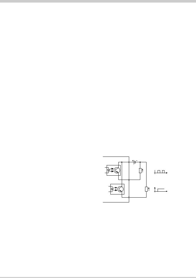
Pulse/limit value outputs 

Depending on the function selected, the two digital outputs can be used either as pulse outputs for actual and reactive energy or as limit signals.
The outputs are passive, and are galvanically isolated from all the other circuits by opto-couplers. They are suitable to drive tariff devices (S0-standard DIN 43 864) or 24 V-relais.
Uext |
≤ 40 V DC |
IL |
≤ 150 mA |
|
Uext |
|
20 |
SO2 |
RL |
|
21 |
(OFF: leakage current ≤ 0.1 mA) (ON: terminal voltage ≤ 1.2 V)
U
e.g. energy import
t
SO1 |
RL |
U |
e.g. limit value output |
||
|
22 |
|
Limit value outputs:
the limits can be associated with any measurand. Depending on the type of connection an OR or an AND function is possible for the following values.
3-wire unbalanced load: U12/U23/U31, I1/I2/I3, Iavg1/Iavg2/Iavg3
4-wire unbalanced load: U1/U2/U3, U12/U23/U31, I1/I2/I3, Iavg1/Iavg2/Iavg3, P1/P2/P3, Q1/Q2/Q3, S1/S2/S3, PF1,/PF2/PF3
Alarm ON: |
OR function of the phase measu- |
|
rands |
Alarm OFF: |
AND function of the phase measu- |
|
rands |
Delay time: |
Fixed at 1 s (cannot be modified) |
Camille Bauer |
Data Sheet A 210/A 220 Le – 08.04 |
3 |
 Loading...