

Page 1

sinclair
SPECTRA manual
Page 2

Page 3

sinclair
SPECTRA manual
by Paul Farrow
Third Edition 2013
©2012 by Paul Farrow
www.fruitcake.plus.com
www.zxresourcecentre.co.uk
Page 4

First published 2012
Second edition 2012
Third edition 2013
©2012 Paul Farrow
Front cover illustration by John Harris, and used with kind permission.
Prints of his artwork used for the original ZX Spectrum manual covers are available from:
www.alisoneldred.com/thumbsJohnHarris-Prints-3-1.html
Page 5

Contents
CHAPTER 1
Introduction Page 5
A guide to the features provided by the SPECTRA interface.
CHAPTER 2
Setting up the interface Page 9
How to attach the SPECTRA interface to the Spectrum and how to configure its settings.
CHAPTER 3
SCART connection Page 15
Describes the SCART connection to a TV, including details on the wiring of the cable required and how to
enable sound output. Discusses the purpose of the video signal absent indicator LED and how to resolve
a detected problem.
CHAPTER 4
New display modes Page 21
Describes the range of new display modes available and how they are generated, and provides details
on when you might need to disable them.
CHAPTER 5
Joystick socket Page 43
Describes the pin-out of the joystick socket and how it can be read, and provides details on when you
might need to disable it.
CHAPTER 6
RS232 socket Page 47
Describes the pin-out of the RS232 socket, and includes details on the wiring of a cable suitable for
connecting to a PC. Explains how the socket can be controlled from software, and provides details on
when you might need to disable it.
CHAPTER 7
ROM support Page 57
Explains how to fit an onboard ROM or add support for ZX Interface 2 ROM cartridges, and discusses
the merits and limitations of each option. Describes how to override the Spectrum’s ROM or extend it
with new BASIC commands.
CHAPTER 8
Reset button and expansion bus Page 65
Explains how to use of the reset button, and describes how the rear expansion bus differs to that
exposed by the Spectrum.
APPENDICES
A Power usage Page 71
B Hardware compatibility Page 73
C Troubleshooting Page 75
D References Page 77
Page 6

Page 7

CHAPTER 1
Chapter 1
CHAPTER
Page 8

Page 9

Chapter 1
7
Introduction
The SPECTRA interface is a multi-purpose peripheral designed for use with a 16K or
48K Spectrum (50 Hz model only). It will not operate with a 128K Spectrum.
The SPECTRA interface provides the following facilities:
SCART connectivity using RGB to provide a clearer, brighter and better centred
picture than that achievable using the standard TV connection.
Sound output through the television speaker(s).
New display modes, providing up to 64 colours, increased vertical and
horizontal colour resolution, and multiple screen support.
Kempston compatible joystick socket, with support for auto-fire joysticks.
ZX Interface 1 compatible RS232 serial port.
ZX Interface 2 compatible ROM cartridge socket (optional fit).
Onboard 16K ROM to override or extend the Spectrum’s ROM (optional fit).
Reset button.
Rear gold plated full width expansion bus.
Note that the ROM cartridge socket and the onboard ROM facilities are mutually
exclusive since it is physically only possible to fit one of them.
The photograph below identifies the key items found on the SPECTRA interface.
Identification of SPECTRA interface key items
Page 10

Chapter 1
8
The large square integrated circuit (IC) situated at the centre of the board implements
the core logic that controls the facilities of the SPECTRA interface. It is a high capacity
complex programmable logic device (CPLD) and is analogous to the uncommitted
logic array (ULA) inside the Spectrum.
The interface includes a set of switches that allow specific features to be individually
enabled or disabled, thereby achieving maximum compatibility with other interfaces
and existing software. By default, the SPECTRA board is shipped with all switches set
to the disabled position and hence it initially functions only as a SCART interface.
The video signal absent indicator provides visual feedback should the SPECTRA
interface detect a problem with the signals used from the Spectrum expansion bus
that prevent it from displaying a TV picture via the SCART socket. The indicator, a light
emitting diode (LED), will shine red if such an error is detected. The condition under
which this can occur is described in Chapter 3.
The following items are not included by default with the SPECTRA interface and so
must be obtained separately if the corresponding feature is to be used:
A SCART cable which supports an RGB connection. The vast majority of
commercially available SCART cables will be suitable. The wiring of the cable
required is described in Chapter 3.
A 2 x 15-way edge connector socket (if ROM cartridge support is required).
A 28-way dual-in-line (DIL) IC socket (if an onboard ROM is required).
A serial cable for use with the RS232 socket. The wiring of the cable required is
described in Chapter 6.
In addition, the television must have an RGB enabled SCART socket. There are three
different video formats that a SCART socket may support (RGB, composite video and
S-video) but often a socket will not support all of these. Televisions which have more
than one SCART socket may implement support for a different subset of video formats
on each socket, and so all available sockets should be tried until one is found which
yields a picture. It is advisable to consult the television instruction manual to determine
which of its SCART sockets provide support for connection via RGB.
Throughout the rest of this manual the terms expansion port and expansion bus are
used interchangeably to refer to the connection socket located at the rear of the
Spectrum and on some peripherals. Likewise, the terms interface, peripheral and
device are used interchangeably and refer to a physical board that can be plugged
into the Spectrum’s expansion port.
Page 11

CHAPTER 2
Chapter 2
CHAPTER
Page 12

Page 13

Chapter 2
11
Setting up the interface
Before handling the SPECTRA interface it is advisable to touch a grounded metal
object to ensure you are free of static charge, e.g. external bare metal section of the
casing of a plugged in desktop PC. The board should then only be held by its edges
to reduce the risk of electrostatic discharge damaging the circuitry.
The SPECTRA interface is mounted on four plastic legs, one per corner of the board. If
not already fitted, these must first be attached. Each leg consists of a plastic bolt and a
plastic pillar. To attach a leg, push a bolt through a mounting hole from the top side of
the board and screw it into a pillar held underneath the board. The bolt can easily be
tightened by hand, but a flat bladed screwdriver may be used if preferred.
The SPECTRA interface should be connected to the Spectrum using the following
procedure:
Ensure the television and the Spectrum are both powered off.
Plug the SPECTRA interface into the Spectrum’s expansion port. If you wish to
connect other interfaces then the order in which they are connected becomes
important (see the section below entitled Connection order for details).
Plug one end of the SCART cable into the SPECTRA interface and the other
end into a suitable SCART socket on the television.
Power on the television.
Power on the Spectrum.
The SPECTRA interface generates all necessary signalling voltages into the SCART
socket to inform the television to automatically display the RGB signal, and so there
should be no need to manually select the mode (unless your television does not
implement this feature of the SCART specification). It may take a few moments for the
television to detect the mode signalling and switch to display the SCART socket input.
The video signal absent indicator will light when the SPECTRA interface is powered
on but should almost immediately switch off and remain off. The condition under
which it may remain on is described in Chapter 3.
Connection order
The SPECTRA interface can coexist with other peripherals attached to the Spectrum,
but the order that these peripherals are connected becomes important if the SPECTRA
interface has the onboard ROM or ROM cartridge facility fitted and any of the other
peripherals contain their own ROM or support a plug-in ROM. This is because all
ROMs must share the same address space and as a result only one may ever be
active at a time. If there is only a single ROM based device connected (SPECTRA or
other peripheral) then the order of connection is unimportant.
A peripheral wishing exclusive access to the ROM address space can instruct all
devices connected in front of it to relinquish control. However, it cannot signal such a
Page 14

Chapter 2
12
request to devices connected behind it. A peripheral’s position within the chain of
connected devices therefore sets its access priority to the ROM address space. The
highest priority position is at the end of the chain of devices, with priority decreasing
the closer to the Spectrum a device gets. The lowest priority ROM is always the one
inside the Spectrum. To ensure all connected ROM based devices coexist without
conflict, it is necessary to determine the appropriate priority for each of them. This then
translates directly into the order that they should be connected behind the Spectrum.
Often the connection order of peripherals is quite apparent. For example, the physical
shape of the ZX Interface 1 means it can only be connected directly behind the
Spectrum. Likewise, the reduced width expansion bus at the rear of the ZX Interface 2
means that only a ZX Printer can be connected behind it, and so forces the
ZX Interface 2 to become the last connected ROM based device (the ZX Printer does
not contain a ROM). If a SPECTRA interface were added to a Spectrum system fitted
with a ZX Interface 1 and ZX Interface 2 then clearly there is no choice but to connect
it in between these two devices.
Another factor limiting the connection order is whether a peripheral provides a rear
expansion port. If it does not then it dictates that it must be the last connected device.
Although a cheap option for the manufacturer, it can be a frustration to the user who
finds it prevents the connection of other devices. The ZX Interface 2 falls into this
category, although it does at least provide the ability to connect a ZX Printer behind it.
Sinclair imposed this limitation on the ZX Interface 2 purely to keep the cost of its
manufacture to a minimum. Ideally, a ROM based device should disable its ROM
whenever it detects a peripheral connected behind it is requesting access to the ROM
address space. However, to do this requires circuitry, and hence increased cost.
Sinclair removed the need for this cost in the ZX Interface 2 by simply ensuring that no
other Spectrum peripheral could be connected behind it. Sinclair needed a way to
allow a ZX Printer to be connected since it was an official peripheral sold for the
Spectrum. It could not be connected ahead of the ZX Interface 2 since it used a
smaller width edge connector (having originally been developed for use with the
ZX81), but this worked in Sinclair’s favour because it allowed the ZX Interface 2 to be
equipped with a rear expansion bus only wide enough and only exposing those
signals required by the ZX Printer.
Even though a peripheral might provide a rear full width expansion port, it does not
necessarily follow that all signals are routed to it and so there may be little choice but
to connect the peripheral behind the SPECTRA interface. If modifying the peripheral is
acceptable then an alternate solution would be to add the missing connections by
soldering wires between the peripheral’s edge connector and its expansion bus,
thereby allowing the peripheral to be connected in front of the SPECTRA interface.
For ROM based peripherals that do provide a complete rear expansion port, the order
they should be connected in depends upon the functionality they provide. ROM based
devices fall into three categories:
Page 15

Chapter 2
13
1. The device supplements the Spectrum’s BASIC ROM by becoming active when a
BASIC error occurs or when particular BASIC commands are executed, e.g.
ZX Interface 1, floppy disk interface, Centronics printer interface.
2. The device temporarily overrides the Spectrum’s ROM when instigated by manual
intervention from the user, e.g. pressing the transfer button on a device such as
Romantic Robot’s Multiface or Datel’s Snapshot. Note that the Snapshot interface
actually contains an onboard RAM that must be initially loaded with the transfer
program from cassette. However, for the purposes of this document any interface
that operates using RAM in this manner is still deemed a ROM based device since
it operates by overriding the Spectrum’s ROM.
3. The device permanently overrides the Spectrum’s ROM, e.g. the ROM cartridges of
the ZX Interface 2.
Typically, these categories form the order in which device types should be connected,
i.e. those that supplement the Spectrum’s BASIC ROM should be connected first,
followed by those that temporarily override the Spectrum’s ROM, and finally those that
permanently override the Spectrum’s ROM. Devices that fall within the same category
may generally be connected in any order, unless the instructions for a particular device
specifies otherwise.
Note that some ROM based peripherals that provide a full rear expansion port might
not monitor for devices connected behind them requesting access to the ROM
address space. Such peripherals should be connected at the end of the chain of
attached devices, but identifying them could prove a problem since there is no
obvious visual indication (a detailed examination of their circuitry is the only way). An
example of such a device is the RAM Turbo interface (a ZX Interface 2 clone, providing
ROM cartridge and twin joystick sockets).
Another potential problem can occur with devices that provide a Kempston joystick
interface but do not fully decode it on input port 31. The RAM Turbo is one such
device, which only decodes address line A5 instead of A5, A6 and A7. This causes it to
clash with the display mode register provided by the SPECTRA interface (described in
Chapter 4). The SPECTRA interface prevents these clashes occurring if such devices
are connected behind it (see Chapter 8 for further details).
The SPECTRA interface can support an onboard ROM or a ROM cartridge socket, but
if neither of these options has been fitted then the interface can be safely connected
anywhere along the chain of devices. When one of these options has been fitted, the
SPECTRA interface can be configured to operate as a device of category 1 or 3. Its
ROM may be configured to supplement the Spectrum’s BASIC ROM, in which case it
should be connected towards the front of the chain of attached devices. Or its ROM
may be configured to permanently override the Spectrum’s ROM just like a
ZX Interface 2 ROM cartridge, in which case the SPECTRA interface should be
connected towards the end of the chain of attached devices. However, unlike the
ZX Interface 2, the SPECTRA interface does monitor for devices connected behind it
requesting access to the ROM address space. This allows the SPECTRA interface to
Page 16

Chapter 2
14
be fitted with a ROM containing a modified version of Spectrum BASIC and for devices
that were designed to supplement or interrupt the Spectrum’s BASIC ROM to be
connected behind it and to operate on the modified version instead, e.g. Multiface,
Centronics printer interface. When used in this configuration, the SPECTRA interface
should ideally be connected immediately behind the Spectrum, but this may not
always be possible, e.g. when a ZX Interface 1 is also connected. In such a case, the
ZX Interface 1 would not be able to intercept the ROM fitted on the SPECTRA interface
and so its extended BASIC commands would not be available.
Configuration switches
The SPECTRA interface contains 6 switches that are used to enable / disable the
various facilities it provides. The configuration switches are numbered 1 to 6 and
perform the following functions:
1. Enables sound output through the television’s speaker(s).
2. Enables an onboard ROM to override the Spectrum’s ROM.
3. Enables an onboard ROM or ROM cartridge to extend the Spectrum’s ROM.
4. Enables the RS232 socket.
5. Enables the Kempston joystick socket.
6. Enables the new display modes.
A facility is disabled when its control switch is set to the off position (the slider pushed
to the left), and enabled when set to the on position (the slider pushed to the right).
The use of each switch is described in the chapter that corresponds to the facility it
controls. When operating the switches, avoid placing pressure downwards as this can
damage them and ultimately prevent them from working reliably.
Page 17

CHAPTER 3
Chapter 3
CHAPTER
Page 18

Page 19
Chapter 3
17
SCART connection
The SCART socket provided by the SPECTRA interface connects to a television using
a standard SCART cable. It outputs a RGB signal to produce a high quality picture,
and allows the Spectrum’s sound to be played through the television’s speaker(s). It
also provides the necessary control voltages required to instruct the television to
automatically select the RGB signal of the SCART socket.
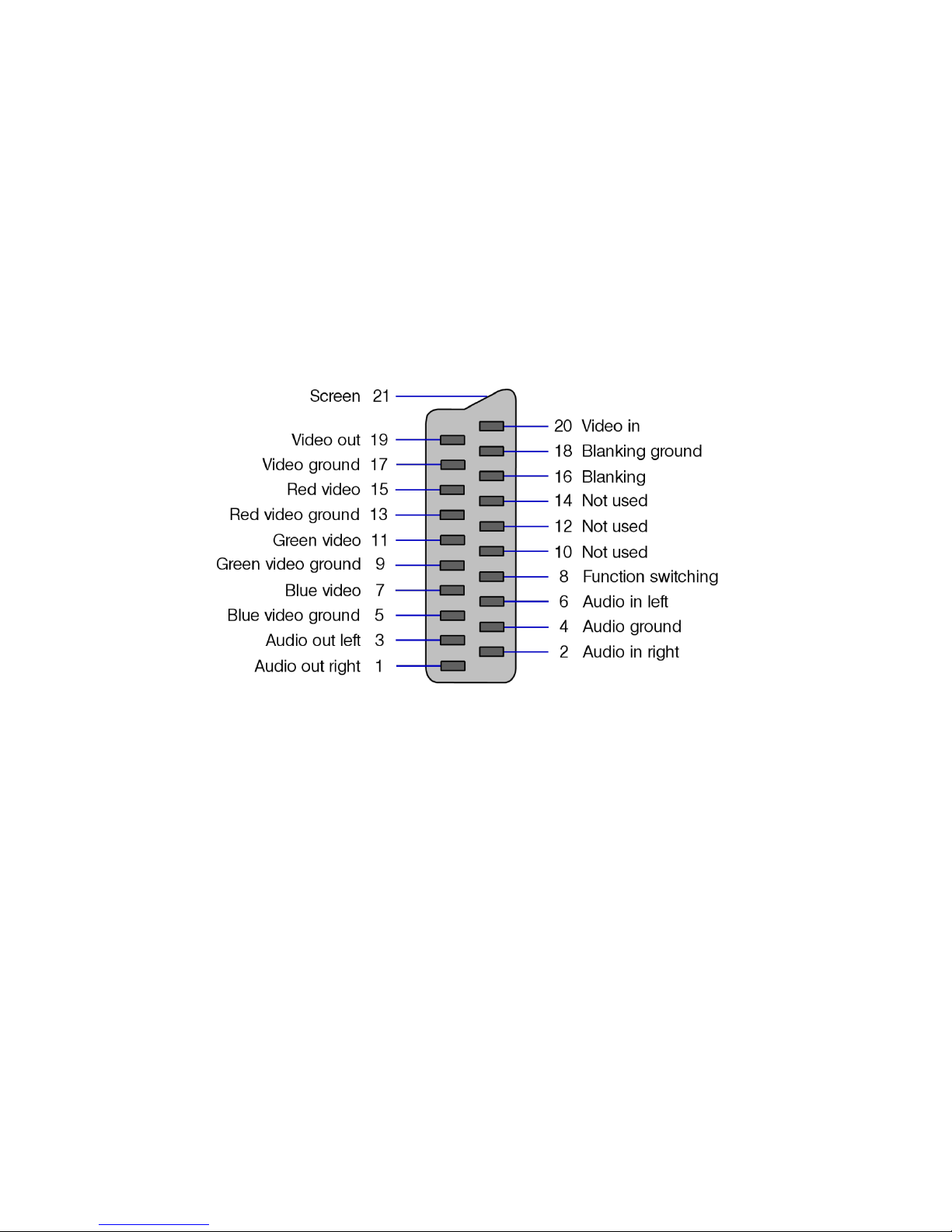
The majority of commercially available SCART cables will be suitable. Alternatively, it is
possible to construct your own lead. The diagram below shows the pin-out of the
SCART socket provided by the SPECTRA interface.
Front view of the SPECTRA SCART socket
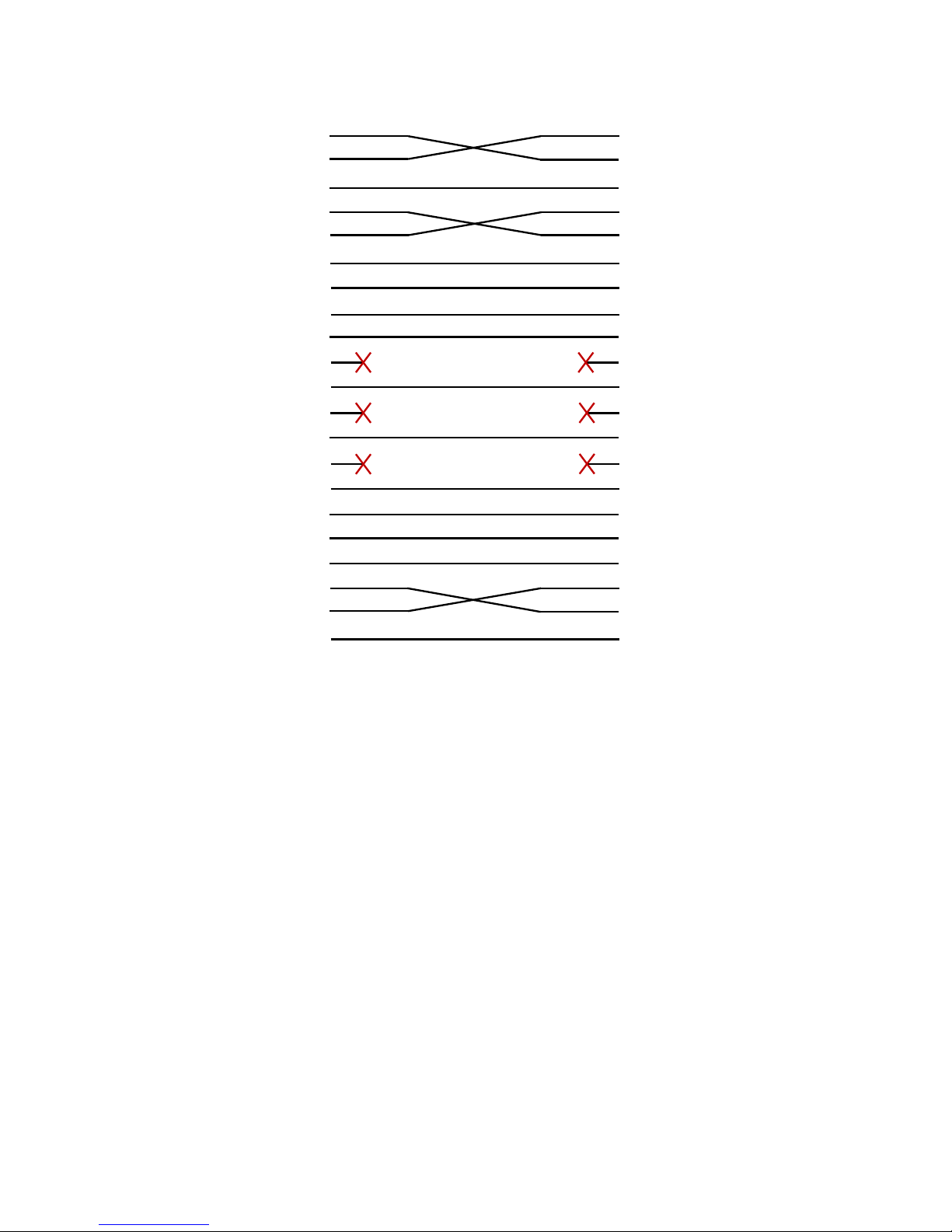
The wiring of a SCART cable suitable for use with the SPECTRA interface is shown on
the next page, and results in a cable that can be connected either way round. The
ground connections (pins 4, 5, 9, 13, 17 and 18) may be wired individually pin-to-pin
between the SCART plugs, or they may all be tied together and linked using a single
connection. The cable should be screened to minimise interference.
Modern televisions typically perform processing on an incoming signal to try to
improve the quality of the displayed picture, e.g. sharpening, motion smoothing, etc.
However, such processing may actually result in a worse picture from the Spectrum
and so it may prove beneficial to disable all such filters.
To enable sound output via the television’s speaker(s), configuration switch 1 must be
set to the on position.
Page 20
Chapter 3
18
SCART Plug
SCART Plug
Audio out right
1 1
Audio out right
Audio in right
2 2
Audio in right
Audio ground
4 4
Audio ground
Audio out left
3 3
Audio out left
Audio in left
6 6
Audio in left
Blue video ground
5 5
Blue video ground
Blue video
7 7
Blue video
Function switching
8 8
Function switching
Green video ground
9 9
Green video ground
Not used
10 10
Not used
Green video
11 11
Green video
Not used
12 12
Not used
Red video ground
13 13
Red video ground
Not used
14 14
Not used
Red video
15 15
Red video
Blanking
16 16
Blanking
Video ground
17 17
Video ground
Blanking ground
18 18
Blanking ground
Video out
19 19
Video out
Video in
20 20
Video in
Screen
21 21
Screen
Wiring of a SPECTRA compatible SCART cable
Video signal absent indicator
The SPECTRA interface uses the luminance (/Y) signal present on the Spectrum’s
expansion bus to synchronise the display it outputs from the SCART socket with the
standard TV picture generated by the Spectrum. This signal is available by default on
the majority of Spectrums, except for issue 1 and early issue 2 machines. In these
issue machines, it is taken to the expansion bus via a short wire link but this link is not
always fitted. On later builds of the issue 2 Spectrum the link was fitted as standard,
and in subsequent issue PCBs the link was removed altogether and replaced with a
continuous track. The purpose of the video signal absent indicator LED on the
SPECTRA interface is to provide a visual indication should the luminance signal not be
found. Note that upon powering up the Spectrum, the LED will light but should then
switch off almost immediately. If it stays on then it is highly probable that the Spectrum
does not have the link fitted and so one must be soldered in.
It is possible to identify an issue 1 or issue 2 Spectrum from a quick visual inspection
through the rear expansion port. If a heatsink cannot be seen spanning across the top
of the expansion bus then the Spectrum is an issue 1 or issue 2 machine. If there is a
daughter board spanning across the expansion bus, then the Spectrum is an issue 1
(the daughter board was used to expand the computer from 16K to 48K, whereas in
Page 21
Chapter 3
19
all later issues the additional RAM was housed directly onboard the main PCB). If a
daughter board is not visible but three thick tracks with about a dozen thinner tracks
beyond them running behind the length of the expansion bus can be seen then the
Spectrum is an issue 1 (all subsequent models have ICs present here instead).
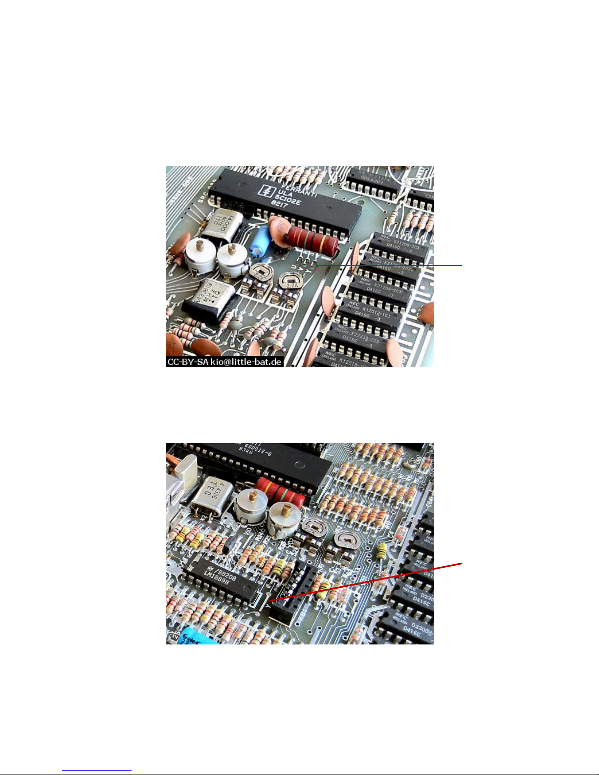
The location to fit the wire link inside an issue 1 Spectrum is shown in the following
photograph:
Luminance wire link position in issue 1 Spectrum
The location to fit the wire link inside an issue 2 Spectrum is shown in the following
photograph:
Luminance wire link position in issue 2 Spectrum
In both cases, the wire link should be fitted between the two holes marked with a
white line and labelled ‘Y’.
Fit wire
link here
Fit wire
link here
Page 22

Page 23

CHAPTER 4
Chapter 4
CHAPTER
Page 24

Page 25

Chapter 4
23
New display modes
Whereas the Spectrum only supports a single limited colour display format, the
SPECTRA interface provides support for an additional 31 display formats. These allow
up to 64 unique colours to be shown simultaneously, and at a variety of colour
resolutions up to eight times higher in the vertical direction and up to two times higher
in the horizontal direction than the standard Spectrum display. The additional colours
may also be applied to the border area, and the interface includes support for multiple
screens (similar in concept to the dual screen mechanism introduced on the
Spectrum 128). These new display modes are achieved without the need for any nonstandard internal modifications to the Spectrum.
The new display modes concentrate on the colour aspect of the screen because it is
the colour abilities of the Spectrum that are arguably in most need of enhancement.
This is due to the design Sinclair used that allowed them to create a computer that
was capable of producing a ‘full colour’ screen using less than 7K of RAM. This feat
was achieved by cleverly superimposing a coarse colour grid (the attributes file) on top
of a finer pixel grid (the display file). This dramatically reduced the amount of RAM
required but resulted in the smallest colour entity covering an area of 8 by 8 pixels,
causing the infamous colour clash effect seen in many Spectrum games. A design
that would have allowed each pixel to be individually set to any of the 8 basic colours
would have required 18K of RAM, which is 2K more than the total memory initially
shipped with the Spectrum!
To understand the remainder of this chapter, it is useful to establish some terminology
to describe the structure of a screen display. The active portion of the Spectrum’s
display consists of 256 pixels in the horizontal direction and 192 pixels in the vertical
direction. The horizontal pixels are grouped into blocks of 8 to form 32 columns. The
vertical pixels are also grouped into blocks of 8 and form 24 rows. The Spectrum’s
display file operates at the pixel level whereas its attributes file operates at the row and
column level. Each byte position in the attributes file is referred to as a cell.
The SPECTRA interface provides support for display modes with attribute heights of 1,
2, 4 and 8 pixels, and widths of 4 and 8 pixels. The height modes are referred to as
single line, dual line, quad line, and row and yield vertical colour resolutions of 192, 96,
48 and 24 attributes respectively. The width modes are referred to as full cell and half
cell and yield horizontal colour resolutions of 32 and 64 attributes respectively. A cell
can therefore hold information for either a single attribute (full cell mode) or two
attributes (half cell mode). In all display modes the display file resolution remains at
256 x 192 pixels. When referring to just those aspects of the display mode that affect
the size and colour range of the attributes file, the term attribute mode is used. The
choice of different attribute modes allows a trade-off between the number of colours,
colour resolution and the memory used for the display information.
Page 26
Chapter 4
24
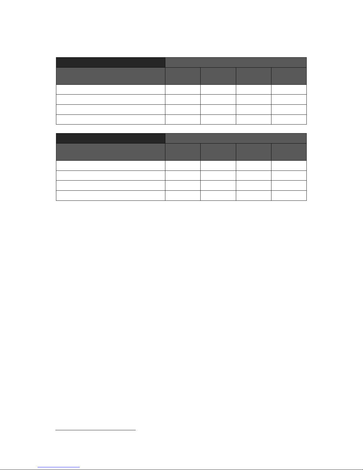
The range of available attribute modes is summarised in the tables below.
Full cell mode
Number of attributes (horizontal x vertical)
Colouring supported
32 x 24
(row)
32 x 48
(quad)
32 x 96
(dual)
32 x 192
(single)
8 ink, 8 paper, bright, flash
8 ink, 8 paper, independent flash
1
64 ink, 2 paper, flash
64 ink, 64 paper, ink flash, paper flash
1
Half cell mode
Number of attributes (horizontal x vertical)
Colouring supported
64 x 24
(row)
64 x 48
(quad)
64 x 96
(dual)
64 x 192
(single)
8 ink, 1 paper, bright, flash
8 ink, 8 paper, independent flash
1
64 ink, 1 paper, flash
64 ink, 1 paper, independent flash
1
Summary of available attribute modes
Note that it is not possible to fully support 64 ink and 64 paper colours at an attributes
file resolution of 32 x 192, or to fully support 8 ink and 8 paper colours at an attributes
file resolution of 64 x 192. This is because these modes would require 2K more RAM
than is available for use by the attributes file. So instead, a composite display is
produced that consists of two areas of different resolutions. The details of this hybrid
display format and why there is a limit to the size of the attributes file are described
later in this chapter.
The new display modes are only available when enabled by setting configuration
switch 6 to the on position.
RGB picture generation
The most obvious approach to generating a RGB picture is to try and decode the YUV
colour difference signals available from the Spectrum’s expansion bus. However, these
signals are subject to so much electrical noise that it is impossible to reliably identify
all shades of colour produced by the Spectrum. A solution which bypasses the noise
is therefore required.
The Spectrum stores its picture display information at the beginning of the lower 16K
RAM bank. The SPECTRA interface listens to all writes to this RAM bank and keeps a
copy of the data in its own onboard RAM. It then uses this copy to independently
generate a TV picture that is identical to the one produced by the Spectrum. By
constructing the TV picture directly from raw display bytes, the issue of electrical noise
is completely circumvented.
1
Due to limited memory availability, this is a hybrid mode consisting of two regions of different line heights.
Page 27

Chapter 4
25
For the technique to work, the generated picture must be in perfect synchronisation
with the standard TV picture to ensure that the SPECTRA interface only reads from its
display RAM at the same moments that the ULA reads from the Spectrum’s internal
display memory. This then avoids the need for the SPECTRA interface to handle
contention conditions with the CPU since the ULA will already be performing this task.
To achieve synchronisation, the SPECTRA interface aligns its display generation with
the interrupt (/INT) and luminance (/Y) signals exposed on the Spectrum’s expansion
bus, which allow the start of each TV frame and the start of each scan line within a
frame to be determined. If the luminance signal is not active on the expansion bus
then the SPECTRA interface cannot synchronise with the standard TV picture and so
will not attempt to generate a display (resulting in a blank screen). This condition is
detected and reported to the user using the video signal absent indicator LED, as
described in Chapter 3.
The SPECTRA interface controls the operation of fetching raw display bytes from its
RAM and processing them to generate the TV picture. However, it does not have to
interpret the bytes in the same manner that the Spectrum interprets those from its
display RAM. Further, since a complete copy of the lower 16K RAM bank is available,
the SPECTRA interface may interpret as much of this RAM as it wishes when
constructing the TV display. This forms the basis of how the new display modes are
achieved.
A consequence of the shadowing approach used by the SPECTRA interface is that it
limits the memory available for the new display modes to 16K, and is because only
this amount is contended with the ULA. Of the 16K, the display file always occupies 6K
and so the maximum size available for the attributes file is 10K. This is why the
SPECTRA interface cannot support an attributes file of resolution of 32 x 192 when
using 64 ink and 64 paper colours, or an attributes file of resolution 64 x 192 when
using 8 ink and 8 paper colours. Although it is theoretically possible to use more of the
16K to create a higher pixel resolution display (albeit at the expense of reducing the
available range of colours and the colour resolution), it was decided to only target the
colour deficiencies of the Spectrum in this version of the SPECTRA interface.
Note that there is actually 32K of RAM onboard the SPECTRA interface, which is
divided into two banks of 16K. Only one of these banks is ever shadowing the
Spectrum’s lower 16K RAM bank, as explained later in this chapter.
The SPECTRA interface generates its TV picture using a similar process to that used
by the Spectrum’s ULA, although it includes additional logic to implement the extra
display modes. For a comprehensive description of how the Spectrum generates its TV
picture, refer to The ZX Spectrum ULA book [1].
The majority of the new attribute modes can only practically be accessed using
machine code but a few can be controlled directly from BASIC and these are
described later in this chapter. The ROM paging mechanism provided by the
SPECTRA interface opens up the possibility to extend Spectrum BASIC with support for
most of new attribute modes, and this is explored further in Chapter 7.
Page 28
Chapter 4
26
Display mode register
The new display modes are selected using an 8-bit register accessed through input /
output (I/O) port $7FDF (where $ denotes the number is in hexadecimal). This register
is only accessible when the new display modes have been enabled by setting
configuration switch 6 to the on position. When enabled, the active display mode is
selected by writing to the output port. The port can also be read back, which is useful
since it provides a means for a program to determine whether the new display modes
functionality is available (the value read back should match the mode previously
selected).
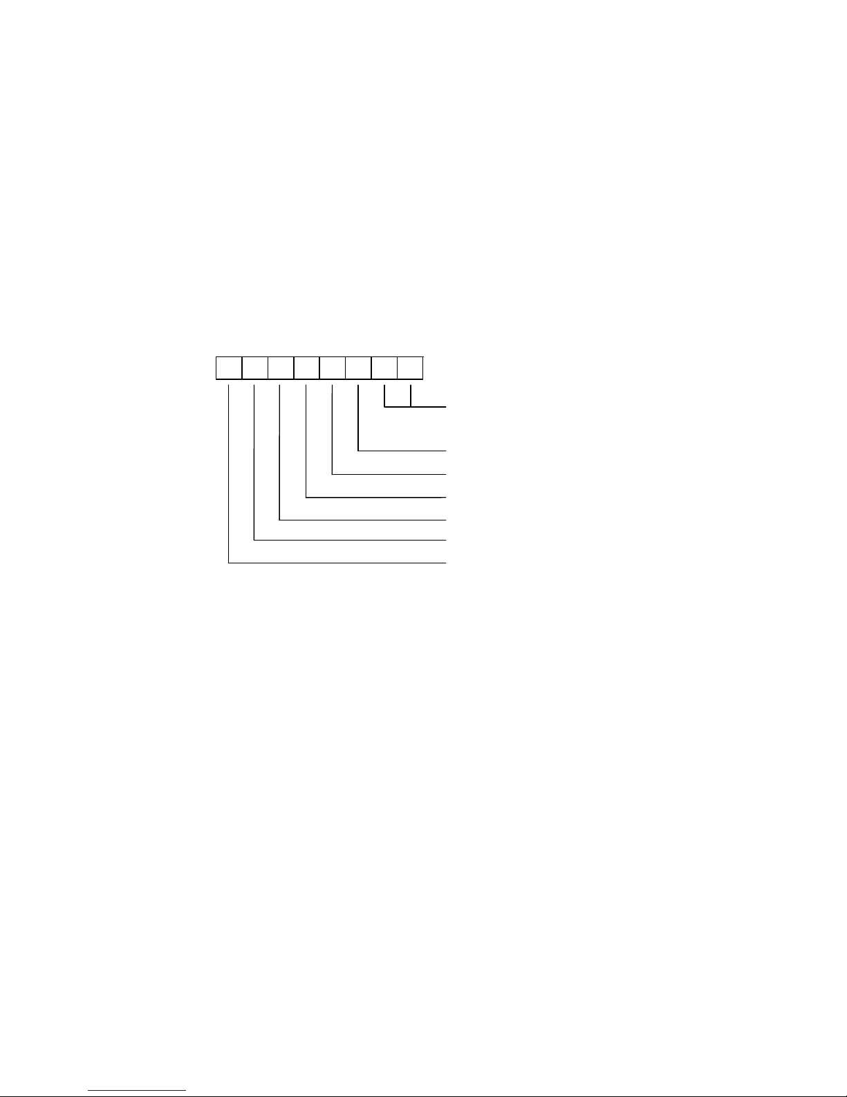
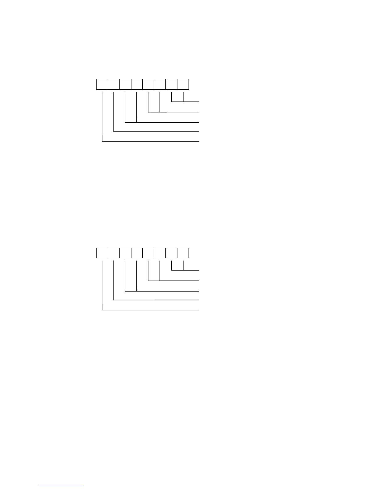
The display mode register is structured as follows:
7 6 5 4 3 2 1
0
Line height:
00=Row, 01=Quad, 10=Dual, 11=Single
0=Basic colours, 1=Extra colours
0=Single byte colour, 1=Double byte colour
0=Standard border, 1=Enhanced border
0=Display bank 0, 1=Display bank 1
0=Shadow bank 0, 1=Shadow bank 1
0=Full cell, 1=Half cell
Each option can be combined with any of the others to form a large range of different
display modes.
The line height bits are used to select how many pixels form the height of a line, either
single line (1 pixel), dual line (2 pixels), quad line (4 pixels) or row (8 pixels).
The basic / extra colours bit selects between the conventional range of 15 colours
provided by the Spectrum and a larger palette of 64 colours.
The single / double byte colour bit selects whether the colour for each attribute
position is specified using single bytes or with two bytes. The interpretation of the
byte(s) depends upon the basic / extra colours bit and the full / half cell bit, and
determines whether the basic palette of 15 colours is available or the enhanced
palette of 64 colours.
The standard / enhanced border bit selects between the conventional border
functionality offered by the Spectrum and new functionality that allows additional
colours to be displayed, including the ability to flash the border.
The display bank 0 / 1 bit is used to specify which half of the 32K RAM fitted onboard
the SPECTRA interface contains the screen information that will be fetched when
generating the TV picture. This facility can be used to store a display screen and then
Page 29

Chapter 4
27
switch back to it when desired. When used with the shadow bank 0 / 1 bit, a double
buffer mechanism is achieved (as described below).
The shadow bank 0 / 1 bit is used to select which half of the 32K RAM fitted onboard
the SPECTRA interface will shadow the Spectrum’s lower 16K RAM. When used with
the display bank 0 / 1 bit, a double buffer mechanism is achieved which allows a
program to be constructing a screen image in the shadow bank while the SPECTRA
interface is outputting the screen information from the display bank. Once construction
of the image has been completed, the roles of the shadow and display banks can be
swapped over, thereby producing an instantaneous update on the television without
any flicker.
The full / half cell bit selects between attributes of 8 pixels wide and 4 pixels wide.
The colour byte(s) read in for a cell (as defined by the single / double byte colour bit)
are interpreted differently for half cell mode than they are for full cell mode. The state of
the basic / extra colours bit determines whether the basic palette of 15 colours or
larger palette of 64 colours is used.
Writing to the display mode register causes an immediate switch to the new
configuration. This can result in a visible flicker should the change occur midway
through a TV frame. Therefore, it may be desirable to wait until an interrupt occurs
before switching to the new mode since this ensures that the change happens prior to
the top border being generated. The immediate switch of display modes opens up the
possibility to force the construction of a hybrid screen by timing the exact moment that
transitions occur between modes.
Note that the standard display mode is always reverted to whenever the reset button is
pressed or when configuration switch 6 is set to the off position. When either condition
happens, the display mode register is loaded with a value of $00 thereby selecting
configuration: row mode, display bank 0, shadow bank 0, standard border, basic
colours, single byte colour and full cell mode.
Display memory organisation
The standard Spectrum screen memory has the pixel display file located at addresses
$4000 to $57FF, and the attributes file located at addresses $5800 to $5AFF. The
ordering of the lines within the display file does not follow a logical progression down
the screen but instead follows the distinctive sequence often seen when a loading
screen is being read in from cassette. This sequence splits the display into 3 areas of
8 rows, with each area ordered by the pixel line positions within the rows. In contrast,
the attributes file is ordered in a logical progression starting from the top row. To
understand why the display file uses such an apparently odd layout requires an
examination of how each memory location within it is addressed. The diagram that
follows shows the addressing schemes for the standard display and attribute files.
Page 30

Chapter 4
28
15
14
13
12
11
10 9 8 7 6 5 4 3 2 1 0
Display file:
0 1 0
A1
A0
L2
L1
L0
R2
R1
R0
C4
C3
C2
C1
C0
Attributes file:
0 1 0 1 1 0 A1
A0
R2
R1
R0
C4
C3
C2
C1
C0
The area number is specified by bits An, the row number within an area by bits Rn, the
pixel line number within a row by bits Ln and the column number by bits Cn. It can be
seen that the lower 8 bits are identical between the display file and the attributes file,
and this approach was used since it simplified the picture generation logic inside the
ULA. Note that the A0 and A1 bits never both hold a value of 1, and thus the display
file and the attributes file can never overlap.
The new attribute modes provided by the SPECTRA interface use an addressing
scheme for the display file that is identical to that used by the standard Spectrum
screen. However, the addressing schemes used for the various display mode attribute
files are different. A relationship between them and the display file can be seen by
examining address lines A8 to A12, which shift by one bit position to the left each time
the vertical colour resolution is doubled. It becomes clear that although the standard
attributes file (row mode) visually appears to be a logical progression, it can actually be
thought of as an extreme case of the ‘odd’ sequence seen in the display file. The
addressing schemes for the new attribute modes are shown below.
15
14
13
12
11
10 9 8 7 6 5 4 3 2 1 0
Display file:
0 1 0
A1
A0
L2
L1
L0
R2
R1
R0
C4
C3
C2
C1
C0
Row mode:
0 1 0 1 1 D A1
A0
R2
R1
R0
C4
C3
C2
C1
C0 Quad line mode:
0 1 1 0 D
A1
A0
L2
R2
R1
R0
C4
C3
C2
C1
C0
Dual line mode:
0 1 1 D A1
A0
L2
L1
R2
R1
R0
C4
C3
C2
C1
C0
Single line mode – basic / extra colours using single byte colour:
0 1 1 A1
A0
L2
L1
L0
R2
R1
R0
C4
C3
C2
C1
C0
Single line mode – basic / extra colours using double byte colour:
Single line area:
0 1 1 D A0
L2
L1
L0
R2
R1
R0
C4
C3
C2
C1
C0
Dual line area:
0 1 0 1 1 D L2
L1
R2
R1
R0
C4
C3
C2
C1
C0
The bit denoted by D applies to double byte colour and its action depends upon the
full / half cell bit of the display mode register. In full cell mode and in half cell mode
Page 31

Chapter 4
29
using basic colours, it selects between the ink bytes (when D is 0) and the paper bytes
(when D is 1). In half cell mode using extra colours, it selects between the ink bytes for
the right half of each cell (when D is 0) and the ink bytes for the left half of each cell
(when D is 1). In single byte colour mode, D is always 0.
Single line mode using double byte colour produces a composite screen consisting of
two areas of different line resolutions – 128 single pixel height lines followed by 32
double pixel height lines. Both areas support the same colour palette, as specified by
the basic / extra colours bit of the display mode register.
The size of the attributes file is dictated only by the line height and single / double
byte colour bits of the display mode register. The memory usage for each attribute
mode is shown in the following table.
Line mode
Single byte colour
Double byte colour
Row
$5800-$5AFF
[$0300]
$5800-$5AFF
$5C00-$5EFF
[$0600]
Quad
$6000-$65FF
[$0600]
$6000-$65FF
$6800-$6DFF
[$0C00]
Dual
$6000-$6BFF
[$0C00]
$6000-$6BFF
$7000-$7BFF
[$1800]
Single
$6000-$77FF
[$1800]
$5800-$7FFF
[$2800]
Summary of attribute mode memory usage
In double byte colour mode, the attributes file consists of two distinct areas. The first
generally holds the ink bytes for each cell and the second holds the paper bytes for
each cell (the exception to this is half cell mode with extra colours and using double
byte colour, and the format it uses is described later in this chapter). This partitioning
comes about because of the addressing schemes used, but has the advantage that it
becomes easy to find the corresponding paper byte for an ink byte, and vice versa. It
also makes it easy for a program to operate only on the ink or paper bytes instead of
having to manipulate both, and this could be exploited to achieve improved
performance.
As previously stated, single line mode using double byte colour produces a display
that consists of two different line heights. The attributes file spans locations $5800 to
$7FFF, of which the single line data occupies $6000 to $7FFF and the dual line data
occupies $5800 to $5FFF. Both areas are divided in two, with the first half defining the
ink colours and the second half defining the paper colours.
The total number of bytes used by each attribute mode is shown by the number in
square brackets, and excludes any unused region in between the two attribute areas.
This region, if it exists, is available for use by a program.
Page 32
Chapter 4
30
In half cell mode with extra colours and using double byte colour, the first half of the
attributes file holds the colour for the right half of each cell and the second half of the
attributes file holds the colour for the left half for each cell.
Colour byte formats
The SPECTRA interface drives its SCART socket using 6 colour lines, two for each of
the red, green and blue channels. This yields 4 levels for each channel, and they
correspond to approximately 0%, 33%, 66% and 100% of full brightness. When the
channels are combined, a total of 64 different colours can be produced. Of these 15
match the basic range of colours achievable on the standard Spectrum display. It is
the state of the basic / extra colours bit of the display mode register that selects
whether a basic colour palette or the larger 64 colour palette is used.
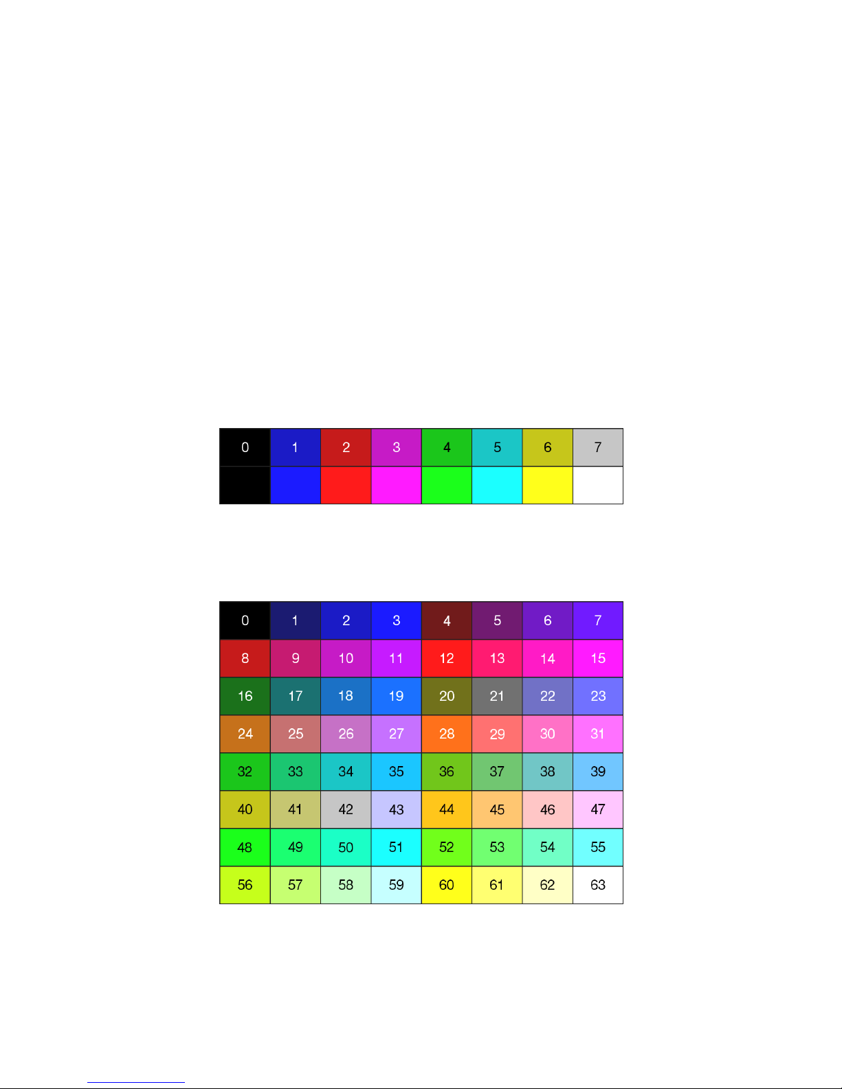
The basic colour palette, including each colour’s index number and bright variation, is
shown below. Note that some attribute modes can only show the non-bright colours
due to a lack of resources in the SPECTRA interface to add support for the full range.
Basic colour palette
The 64 colour palette, including each colour’s index number, is shown below.
64 colour palette
The state of the single / double byte colour bit of the display mode register
determines whether the ink and paper colour values for an attribute cell are held in
Page 33

Chapter 4
31
just one byte or separately in two. The interpretation of the attribute byte(s) also
depends upon the state of the full / half cell bit of the display mode register.
A shorthand notation can be used to specify each attribute mode and consists of the
attribute pixel size (width x height) followed by two letters that indicate the colour
mode. The attribute width indicates full cell (8 pixels) or half cell (4 pixels) mode, and
the attribute height indicates row (8 pixels), quad line (4 pixels), dual line (2 pixels) or
single line (1 pixel) mode. The colour mode letters indicate single (S) or double (D) byte
colour, and basic (B) or extra (E) colours. The range of attribute modes, along with the
interpretation of their attribute byte(s), are summarised below. Each mode is described
afterwards in further detail.
Attribute mode
Attribute cell byte 2
Attribute cell byte 1
8x8
SB
8x4
SB
8x2
SB
8x1
SB
F B
Pg
Pr
Pb
Ig
Ir
Ib
8x8
DB
8x4
DB
8x2
DB
8x1
DB
FP
BP – – – Pg
Pr
Pb FI
BI – – – Ig
Ir
Ib
8x8
SE
8x4
SE
8x2
SE
8x1
SE
F P
Ig
Ig
Ir
Ir
Ib
Ib
8x8
DE
8x4
DE
8x2
DE
8x1
DE
FP – Pg
Pg
Pr
Pr
Pb
Pb FI – Ig
Ig
Ir
Ir
Ib
Ib
4x8
SB
4x4
SB
4x2
SB
4x1
SB
F B
ILg
ILr
ILb
IRg
IRr
IRb
4x8
DB
4x4
DB
4x2
DB
4x1
DB
FP
BP
PLg
PLr
PLb
PRg
PRr
PRb FI
BI
ILg
ILr
ILb
IRg
IRr
IRb
4x8
SE
4x4
SE
4x2
SE
4x1
SE
F IL
IRg
IRg
IRr
IRr
IRb
IRb
4x8
DE
4x4
DE
4x2
DE
4x1
DE
FP
P
L
*
ILg
ILg
ILr
ILr
ILb
ILb FI
P
R
*
IRg
IRg
IRr
IRr
IRb
IRb
The purpose of each bit in the attribute bytes is denoted by labels F, B, I or P to
indicate whether it defines flash, bright, ink or paper respectively. Subscripts of I and P
indicate that the bit applies only to the ink pixels or only to the paper pixels
respectively. Subscripts of L and R indicate that the bit applies only to the left half or
only to the right half of the attribute cell respectively. Subscripts of g, r and b indicate
the bit specifies the green, red and blue components of the colour respectively. Where
two bits appear within an attribute byte for a single colour component, the right most
bit defines the least significant bit of the colour. A ‘–’ indicates that the bit is available
for use by a program. An ‘*’ indicates the intended purpose of the bit but due to a lack
of resources the SPECTRA interface is unable to support this functionality. In such
cases, the bit should always be set to 0 to ensure forwards compatibility with any
future version of the SPECTRA interface.
Page 34
Chapter 4
32
Full cell
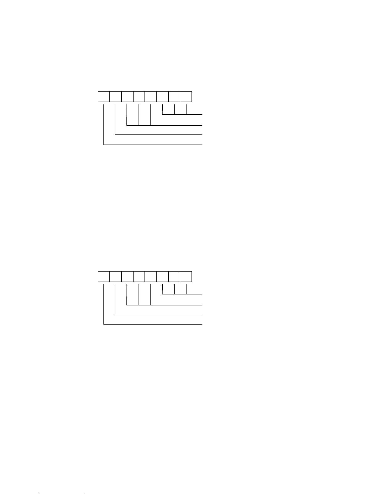
In basic colours mode using single byte colour, each attribute cell is formatted in the
standard Spectrum manner as follows:
7 6 5 4 3 2 1
0
Ink, ordered as GRB
Paper, ordered as GRB
1=Bright
1=Flash
The ink bits define the colour used for those pixels that are set in the display file, and
the paper bits define the colour used for those pixels that are reset. Both values are
composed of 3 bits, yielding a range of 8 colours for each. When coupled with the
bright bit a total of 16 different colour values are produced, although only 15 of these
are unique since black and bright black display the same. When the flash bit is set, the
paper and ink colours swap over at a fixed frequency of 1.565 Hz.
In basic colours mode using double byte colour, the first attribute byte defines the ink
colour and the second attribute byte defines the paper colour. Both bytes are
formatted as follows:
7 6 5 4 3 2 1
0
Colour, ordered as GRB
Unused (available for program use)
1=Bright
1=Flash
The format encodes the ink and paper using 3 bits each, yielding both a range of 8
colours. The bright bit in each byte extends these totals to 16 different colour values,
although only 15 of these are unique since black and bright black display the same.
With the flash bit in both attribute bytes set, the ink and paper colours swap over at a
fixed frequency of 1.565 Hz and replicate the flash mode of the standard Spectrum
display. However, if only the ink attribute byte’s flash bit is set then just the ink coloured
pixels swap between the ink colour and the paper colour, and if only the paper
attribute byte’s flash bit is set then just the paper colour pixels swap between the
paper colour and the ink colour.
Note that the unused bits of each colour byte are available for use as storage by a
program. They could, for example, be used in a maze game to hold flags that indicate
Page 35
Chapter 4
33
which cells contain walls and of what type. If these bits are not used by a program
then it is recommended that they always be set to 0.
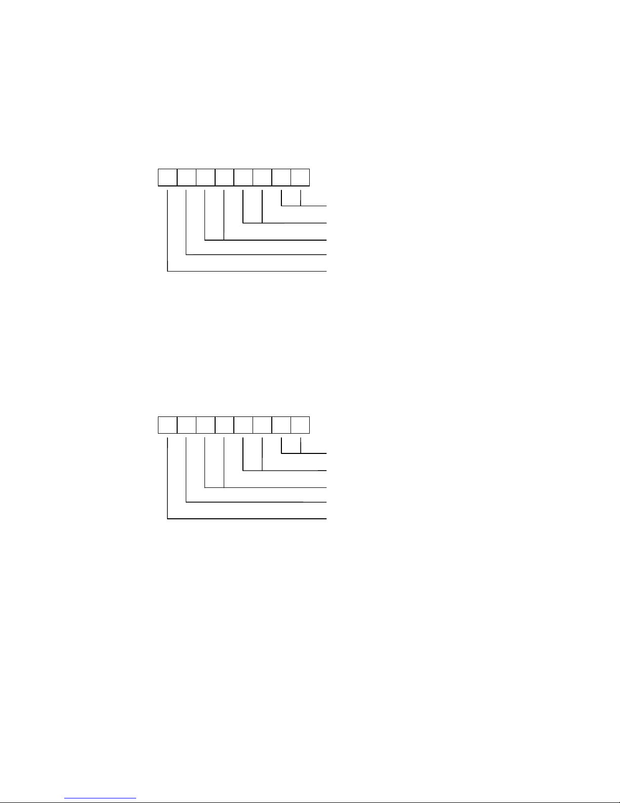
In extra colours mode using single byte colour, each attribute cell is formatted as
follows:
7 6 5 4 3 2 1
0
Blue (ink), ordered as B1B0
Red (ink), ordered as R1R0
Green (ink), ordered as G1G0
0=Black paper, 1=White paper
1=Flash
The format supports 64 ink colours but only 2 paper colours (black and white). When
the flash bit is set, the ink and paper colours swap at a fixed frequency of 1.565 Hz.
In extra colours mode using double byte colour, the first attribute cell byte specifies the
ink colour and the second attribute cell byte defines the paper colour. Both bytes are
formatted as follows:
7 6 5 4 3 2 1
0
Blue, ordered as B1B0
Red, ordered as R1R0
Green, ordered as G1G0
Unused (available for program use)
1=Flash
The format supports 64 colours for the ink and 64 colours for the paper, resulting in a
total of 64 x 64 = 4096 different combinations. When the flash bits are taken into
account, the number of combinations rises to 4096 x 2 x 2 = 16384.
With the flash bit in both attribute cell bytes set, the ink and paper colours swap over
at a fixed frequency of 1.565 Hz. However, if only the ink attribute byte’s flash bit is set
then just the ink coloured pixels swap between the ink colour and the paper colour,
and if only the paper attribute byte’s flash bit is set then just the paper colour pixels
swap between the paper colour and the ink colour.
Note that the unused bit of each attribute byte is available for use as storage by a
program. It is recommended that these bits are always be set to 0 if not used.
Page 36

Chapter 4
34
Half cell
In basic colours mode using single byte colour, the ink colour for the left and right
halves of each cell can be set independently to any of the basic 8 colours. The paper
colour is always black. The format of each attribute cell is as follows:
7 6 5 4 3 2 1
0
Right half ink, ordered as GRB
Left half ink, ordered as GRB
1=Bright
1=Flash
The bright bit applies to the full cell and allows a total of 16 different colour values to
be produced, although only 15 of these are unique since black and bright black
display the same. The flash bit applies to the full cell and when set causes the ink
colours to swap over with the paper colour at a fixed frequency of 1.565 Hz.
In basic colours mode using double byte colour, the first attribute cell byte defines the
ink colour for the two halves of the cell and the second attribute cell byte defines the
paper colour for the two halves of the cell. Both bytes are formatted as follows:
7 6 5 4 3 2 1
0
Right half colour, ordered as GRB
Left half colour, ordered as GRB
1=Bright
1=Flash
The format encodes the left ink, the right ink, the left paper and the right paper using 3
bits, yielding each a range of 8 colours. Both bytes include a bright bit, allowing a total
of 16 different colour values to be produced for the ink and 16 for the paper, although
in each instance only 15 of these are unique since black and bright black display the
same. The brightness of the left ink and right ink will always be the same, and likewise
the brightness of the left paper and right paper will always be the same.
With the flash bit in both attribute cell bytes set, all ink and paper colours in the cell
swap over at a fixed frequency of 1.565 Hz. However, if only the ink attribute byte’s
flash bit is set then just the ink coloured pixels in the cell swap between the ink colour
and the paper colour, and if only the paper attribute byte’s flash bit is set then just the
paper colour pixels in the cell swap between the paper colour and the ink colour.
Page 37
Chapter 4
35
In extra colours mode using single byte colour, each attribute cell is formatted as
follows:
7 6 5 4 3 2 1
0
Right half ink (blue), ordered as B1B0
Right half ink (red), ordered as R1R0
Right half ink (green), ordered as G1G0
Left half ink (0=Black, 1=White)
1=Flash
The format supports 64 ink colours for the right half of the attribute cell but only 2 ink
colours for the left half of the attribute cell (black and white). The paper colour is
always black. When the flash bit is set, the ink and paper colours swap over at a fixed
frequency of 1.565 Hz.
In extra colours mode using double byte colour, the first attribute cell byte defines the
ink colour for the right half of the cell and the second attribute cell byte defines the ink
colour for the left half of the cell. Both bytes are formatted as follows:
7 6 5 4 3 2 1
0
Blue (ink), ordered as B1B0
Red (ink), ordered as R1R0
Green (ink), ordered as G1G0
Reserved for ‘paper’ (always set to 0)
1=Flash
The format supports 64 ink colours for both the left and right halves of the attribute cell.
Although the format includes a paper bit to allow support for two background colours
(0=black and 1=white), this is not supported by the SPECTRA interface due to a lack of
resources and so only a paper colour of black is available. The bit is therefore marked
as reserved and should always be set to 0 to ensure compatibility with any future
version of the SPECTRA interface.
With the flash bit in both attribute cell bytes set, all ink and paper colours in the cell
swap over at a fixed frequency of 1.565 Hz. However, if only the first attribute byte’s
flash bit is set then just the right half ink coloured pixels swap between the ink colour
and the paper colour, and if only the second attribute byte’s flash bit is set then just
the left half ink coloured pixels swap between the ink colour and the paper colour.
Page 38

Chapter 4
36
Standard / enhanced border
The colour of the border in the standard screen display produced by the Spectrum is
set by writing to output port $FE, and supports just 8 colours. The SPECTRA interface
extends the number of supported border colours to 64 by re-interpreting the byte
written to output port $FE when the standard / enhanced border bit of the display
mode register is set.
In standard border mode, the byte written is interpreted in the usual way as follows:
7 6 5 4 3 2 1
0
Border colour, ordered as GRB
MIC output
Speaker output
Not used
The mode supports just the basic set of 8 colours available from the Spectrum.
In enhanced border mode, it is the state of the basic / extra colours bit in the display
mode register that determines how the byte written to output port $FE is interpreted.
In enhanced border mode using basic colours, the byte written is interpreted as
follows:
7 6 5 4 3 2 1
0
Border colour, ordered as GRB
MIC output
Speaker output
0=Flash with black, 1=Flash with white
1=Bright
1=Flash
The bright bit is used to increase the intensity of the colour specified by bits 0 to 2,
resulting in 16 possible colour values. However, only 15 of these are unique since
black and bright black display the same.
When the flash bit is set, the border colour alternates at a fixed frequency of 1.565 Hz
between the colour specified by bits 0, 1, 2 and 6, and either black (if bit 5 is reset) or
white (if bit 5 is set).
Page 39
Chapter 4
37
Note that the MIC output and speaker output bits cannot be re-interpreted since they
are used by the Spectrum’s hardware to control the cassette sockets and the
loudspeaker.
In enhanced border mode using extra colours, the byte written to output port $FE is
interpreted as follows:
7 6 5 4 3 2 1
0
Border colour bits, ordered as G1R1B1
MIC output
Speaker output
Border colour bits, ordered as G0R0B0
The two sets of border colour bits are combined to form a 6 bit value, giving a range of
64 unique colours. They are split into high and low order bits to provide a degree of
backwards compatibility with standard border mode. Note that there is no facility in
this mode to flash the border.
Screen bank 0 / 1
As previously described, the SPECTRA interface contains onboard RAM and uses it to
shadow the Spectrum’s lower 16K RAM bank. The onboard RAM has a capacity of
32K and so is divided into two banks of 16K. The screen bank 0 / 1 bit selects which
bank is read by the SPECTRA interface when generating the TV picture.
The screen bank facility can effectively increase the Spectrum’s available memory by
off-loading a display from main memory into the inactive screen bank. This display can
then be switched to as and when needed. For example, the loading screen for a game
could be stored and then re-shown each time the game is over.
The screen bank 0 / 1 bit operates with all available attribute modes. However, it does
not affect the border area since this is not stored in the Spectrum’s lower 16K RAM
bank.
Shadow bank 0 / 1
The shadow bank 0 / 1 bit selects which half of the 32K RAM onboard the SPECTRA
interface is shadowing writes to the Spectrum’s lower 16K RAM bank.
When the shadow bank and the screen bank point to the same 16K RAM bank,
changes to the display and attribute files are immediately reflected to the television.
When the shadow bank and the screen bank point at different 16K RAM banks, a
double buffer mechanism is achieved. This allows a program to be constructing one
display while another is being shown. Once all drawing has been completed, the roles
of the screens can be swapped over to achieve a smooth transition to the new display
without any visible appearance of the construction process.
Page 40

Chapter 4
38
The shadow bank 0 / 1 bit operates with all available attribute modes. However, it
does not affect the border area since this is not stored in the Spectrum’s lower 16K
RAM bank.
Display mode compatibility
The new display modes provided by the SPECTRA interface are controlled through a
specific I/O port, but there is the possibility that this port address might also be used
by another peripheral. This could prevent the display mode register from being read, or
could cause the other device to become activated when a write to the display mode
register occurs. Should such a conflict be encountered, then either the peripheral must
be disconnected to allow the new display modes to be used, or the new display
modes must be disabled to allow the peripheral to operate correctly.
The new display modes can be disabled by setting configuration switch 6 to the off
position. This causes the SPECTRA interface to revert to the standard Spectrum
display mode and prevents further accesses to the display mode register, thus
ensuring full I/O compatibility with ‘conflicting’ hardware. Further details about the
compatibility of the SPECTRA interface with existing hardware and software can be
found in Appendix B.
Irrespective of the state of configuration switch 6, the SPECTRA interface will always
output a picture through the SCART socket.
Display mode availability
A program can test whether the new display modes are available by writing a value to
the display mode register and then attempting to read it back. If the values do not
match then the new display modes are not available. A value of $FF should be
avoided since this is the default value returned if the display modes are not enabled or
if a SPECTRA interface is not connected.
Should the value read back be different to that expected (but not $FF) then another
device must have responded to the I/O port read, making it impossible to identify
whether the new display modes are available. Note that such a device could also
respond with a value of $FF, thereby giving the impression that no device responded
to the I/O port read.
It is also possible that a conflicting device just happens to respond with the expected
value, leading to a false detection of the display modes functionality. The chances of
this occurring can be significantly reduced by performing the test several times using
a variety of different values.
Note that the display mode register uses an I/O port that is contended with the ULA,
i.e. it has an address between $4000 and $7FFF. This means that the reading of the
I/O port will be suspended whilst the ULA is fetching video data from the Spectrum’s
RAM and will only continue once the ULA has finished its read. As a result, if the
display mode register is read when a SPECTRA interface is not connected (or the
display modes have been disabled) then a value of $FF will always be returned. This
would not necessarily have been the case if a non-contending I/O port had been used
Page 41

Chapter 4
39
for the display mode register since then the I/O read would not have been suspended
while the ULA performs a memory read. Instead of a value of $FF being read (the state
of an idle data bus), the value returned would have been the display byte being
fetched by the ULA. It would only have proved possible to reliably read the display
mode register by waiting until an interrupt had occurred since this happens prior to the
top border being generated. Using a non-contending I/O port would have made the
process of reading the display mode register slower and more involved.
Display mode control from BASIC
The majority of the new attribute modes can only practically be accessed using
machine code, but those that are row based and use single byte colour can be
controlled directly from BASIC. In addition, the enhanced border and multiple screen
facilities may also be controlled from BASIC. However, it is possible to add support for
other attribute modes by extending BASIC using the ROM facilities provided by the
SPECTRA interface and this is explored in Chapter 7.
The new display modes that can be directly controlled using standard BASIC are:
Full cell, row, extra colours, single byte colour mode (8x8 SE).
Half cell, row, basic colours, single byte colour mode (4x8 SB).
Half cell, row, extra colours, single byte colour mode (4x8 SE).
Enhanced border (when in 8x8 SB, 8x8 SE, 4x8 SB or 4x8 SE).
Multiple screen mechanism (when in 8x8 SB, 8x8 SE, 4x8 SB or 4x8 SE).
The following program demonstrates full cell, row, extra colours, single byte colour
mode (8x8 SE) by displaying all colour combinations available:
10 OUT 32735,4
20 DEF FN p(c)=INT (c/8):
DEF FN i(c)=c-8*FN p(c)
30 FOR f=0 TO 1
40 FOR p=0 TO 1
50 FOR n=0 TO 1
60 FOR i=0 TO 63
70 PRINT FLASH f; INVERSE n; BRIGHT p;
PAPER FN p(i); INK FN i(i);"a";
80 NEXT i
90 NEXT n
100 NEXT p
110 NEXT f
The ink pixels can be set to any of 64 colours and the paper pixels can be set to black
and white only. The program sets the ink pixel colour through the combined use of
BASIC commands INK and PAPER, with DEF FN statements being used to simplify
the process of translating the 64 palette colour into values to pass to the INK and
PAPER commands. The paper pixel colour is set through the use of the BASIC
command BRIGHT. The BASIC commands FLASH and INVERSE operate as usual.
Page 42

Chapter 4
40
The following program demonstrates half cell, row, basic colours, single byte colour
mode (4x8 SB) by displaying all colour combinations available:
10 OUT 32735,128
20 FOR n=0 TO 1
30 FOR p=0 TO 7
40 FOR f=0 TO 1
50 FOR b=0 TO 1
60 FOR i=0 TO 7
70 PRINT FLASH f; BRIGHT b; INVERSE n;
PAPER p; INK i;"a";
80 NEXT i
90 NEXT b
100 NEXT f
110 NEXT p
120 NEXT n
The ink pixels of the left and right halves of each cell can be set to any of the basic 8
colours, with the paper pixels always being set to black. The program sets the ink pixel
colour through the combined use of BASIC commands INK and PAPER, with the
BASIC commands FLASH, BRIGHT and INVERSE operating as usual.
The following program demonstrates half cell, row, extra colours, single byte colour
mode (4x8 SE) by displaying all colour combinations available:
10 OUT 32735,128+4
20 DEF FN p(c)=INT (c/8):
DEF FN i(c)=c-8*FN p(c)
30 FOR f=0 TO 1
40 FOR p=0 TO 1
50 FOR n=0 TO 1
60 FOR i=0 TO 63
70 PRINT FLASH f; BRIGHT p; INVERSE n;
PAPER FN p(i); INK FN i(i);"a";
80 NEXT i
90 NEXT n
100 NEXT p
110 NEXT f
The ink pixels of the right half of each cell can be set to any of 64 colours but the ink
pixels of the left half of each cell can only be set to black or white. The paper pixels
are always set to black. The program sets the ink pixel colour through the combined
use of BASIC commands INK and PAPER, with DEF FN statements being used to
simplify the process of translating the 64 palette colour into values to pass to the INK
and PAPER commands. The paper pixel colour is set through the use of the BASIC
command BRIGHT. The BASIC commands FLASH and INVERSE operate as usual.
This mode is probably of limited use due to the left half of each cell only supporting
ink colours of black or white.
The enhanced border functionality can be controlled when in any of the row based
attribute modes that use single byte colour, i.e. 8x8 SB, 8x8 SE, 4x8 SB and 4x8 SE.
The following program demonstrates access to the 64 colour palette when in extra
colours mode (8x8 SE).
Page 43

Chapter 4
41
10 OUT 32735,20
20 DEF FN p(c)=INT (c/8):
DEF FN i(c)=c-8*FN p(c):
DEF FN b(c)=32*FN p(c)+FN i(c)
30 FOR c=0 TO 63
40 OUT 254,FN b(c)
50 PAUSE 25
60 NEXT c
70 GO TO 30
The program cycles through all available colours. DEF FN statements are used to
simplify the process of translating the 64 colour palette into a value to output to I/O
port 254 ($FE).
The multiple screen mechanism can be controlled when in any of the row based
attribute modes that use single byte colour, i.e. 8x8 SB, 8x8 SE, 4x8 SB and 4x8 SE. It
can be used to just store a screen image for display later, or it can be used to
implement a double buffer mechanism. The following program demonstrates this latter
use and displays screens of random numbers one after the other. To see the effect of
screen buffering, uncomment lines 10 and 60. Line 10 selects screen bank 0 for
display and screen bank 1 to shadow the Spectrum's lower 16K RAM bank. Line 60
reverses this to select screen bank 1 for display and screen bank 0 to shadow the
Spectrum's lower 16K RAM bank.
10 REM OUT 32735,64
20 CLS
30 FOR r=0 TO 20
40 PRINT RND
50 NEXT r
60 REM OUT 32735,32
70 CLS
80 FOR r=0 TO 20
90 PRINT RND
100 NEXT r
110 IF INKEY$="" THEN GO TO 10
120 OUT 32735,0
With screen buffering enabled, the process of printing to the screen becomes invisible
to the user. The program still takes the same length of time to output the random
numbers but the visual result can be more pleasing to the eye. To terminate the
program, hold down any key and the program will end by reverting to the standard
display mode.
It may be desirable for a program to adjust its output depending upon whether the
new display modes of the SPECTRA interface are available or not. The following
program demonstrates how this can be achieved from BASIC:
10 OUT 32735,16
20 PRINT "New display modes: ";
30 IF IN 32735<>16 THEN PRINT "not ";
40 PRINT "available"
50 OUT 32735,0
Page 44

Page 45

CHAPTER 5
Chapter 5
CHAPTER
Page 46

Page 47

Chapter 5
45
Joystick socket
The SPECTRA interface includes a Kempston compatible joystick socket, which is the
most widely supported standard by Spectrum games. The socket provides a +5V
output allowing it to drive the auto-fire mode found on many popular joysticks. To use
the joystick socket, it must first be enabled by setting configuration switch 5 to the on
position.
If a separate Kempston joystick interface or a peripheral which includes a Kempston
joystick socket is used then it is necessary to disable the one built into the SPECTRA
interface to prevent a conflict and potential damage to the hardware.
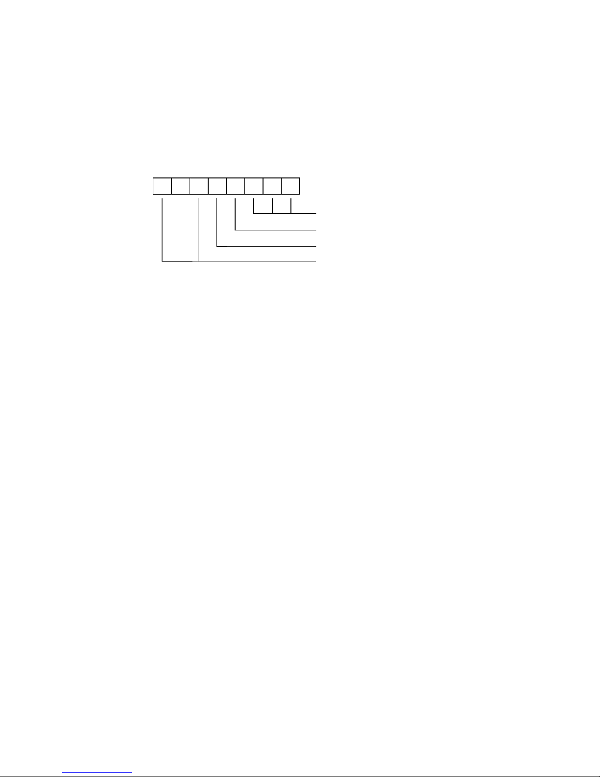
The Kempston joystick socket is read using input port 31 and returns a byte that
decodes as follows:
7 6 5 4 3 2 1
0
1=Right
1=Left
1=Down
1=Up
1=Fire
0=Not used (always 0)
0=Not used (always 0)
0=Not used (always 0)
Each joystick direction bit and the fire button bit is set to 1 when its corresponding
function is activated. The Kempston standard specifies that the upper 3 bits should
always return 0, although it is best not to rely on this since some 3rd party Kempston
joystick interfaces do not bother to set these bits.
The joystick socket can be read from BASIC using the IN function, as the following
program demonstrates:
10 PRINT AT 0,0;IN 31;" "
20 GOTO 10
When the joystick socket is disabled via configuration switch 5, reading the port may
return apparently random values instead of the expected value of $FF (for an idle data
bus). It is due to screen bytes appearing on the data bus as a result of the ULA
reading the display RAM during construction of the TV picture.
Page 48
Chapter 5
46
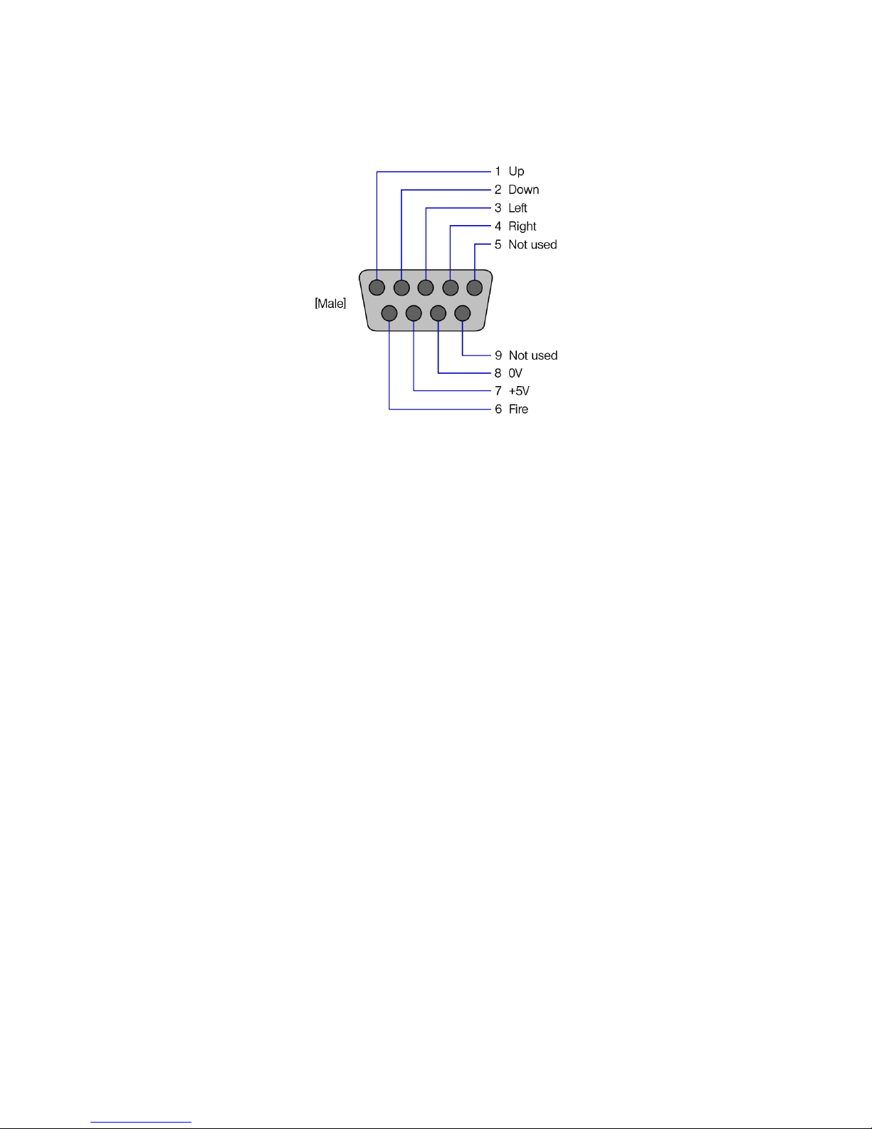
The SPECTRA interface provides a standard male DE-9 joystick socket, which has the
following pin-out:
Top view of the SPECTRA joystick socket
Page 49

CHAPTER 6
Chapter 6
CHAPTER
Page 50

Page 51

Chapter 6
49
RS232 socket
The RS232 socket provided by the SPECTRA interface is fully compatible with the
RS232 port available on the ZX Interface 1. This means that machine code routines
intended to directly drive the ZX Interface 1 RS232 port will operate the SPECTRA
RS232 port without the need for modification. In addition, the ROM facilities provided
by the SPECTRA interface (see Chapter 7) allow the RS232 port to be controlled
directly from BASIC by extending the Spectrum’s ROM with a copy of the
ZX Interface 1 ROM. It is then possible to open text and binary channels using
standard ZX Interface 1 BASIC syntax and hence to run programs originally written to
control the ZX Interface 1 RS232 port. The RS232 socket can be used to connect to a
range of devices, e.g. a serial printer, a modem, a PC to load/save data. For details on
how to control the RS232 port using extended BASIC commands, refer to the
ZX Spectrum Microdrive and Interface 1 Manual [2].
To use the RS232 socket, it must be enabled by setting configuration switch 4 to the
on position. If a ZX Interface 1 is also to be connected then it is necessary to disable
the RS232 socket built into the SPECTRA interface to prevent a conflict and potential
damage to the hardware.
The RS232 port is capable of transmission speeds up to 19200 baud, and typically
sends and receives using 8 data bits, no parity, 2 stop bits and using hardware
handshaking (although the format can be different if you write your own custom serial
driver routines in machine code).
Cable wiring
The SPECTRA interface uses a female DE-9 socket for the RS232 port. This is pin
compatible with the ZX Interface 1 RS232 socket and has the following pin-out:
Front view of the SPECTRA RS232 socket
A custom cable is required to connect the RS232 socket to a serial device. The wiring
needed to connect to a device with a male 9 pin DE-9 connector or a male 25 pin
DB-25 connector is shown below.
Page 52
Chapter 6
50
SPECTRA / ZX Interface 1
Serial Device
DE-9
Male
DE-9
Female
DB-25
Female
TX data
2 3
2
TXD
RX data
3 2
3
RXD
0V
7 5
7
GND
DTR
4 4
20
DTR
CTS
5 8
5
CTS
+9V
9 6
6
DSR
Screen
Screen
Screen
Wiring of a SPECTRA / ZX Interface 1 RS232 cable
Note that the screen connection should be made as this will significantly improve the
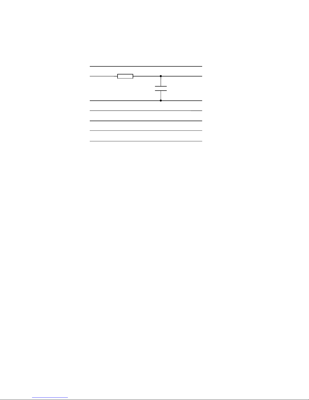
cable’s resilience to interference. A typical RS232 cable may be up to 15m in length.
The cable should include a simple filter circuit consisting of a 1k5 resistor and a 10nF
capacitor. Including the filter circuit creates a standard cable design that can be used
with the RS232 socket of the ZX Interface 1 as well as that of the SPECTRA interface.
The filter circuit is used to minimise the effects of a glitch that occurs on the output
data line from the ZX Interface 1 upon every transmission. The glitch occurs because
the ZX Interface 1 hardware shares the output data line between the Network ports
and the RS232 port and the ROM always reverts back to Network mode after each
RS232 transmission. It is this switching action between Network mode and RS232
mode that causes the glitch.
In general, the two devices connected via an RS232 communications link are referred
to as the data terminal equipment (DTE) and the data communications equipment
(DCE). Normally the DTE would be viewed as the device that requires sending /
receiving of data and the DCE as the device that accepts it or provides it, e.g. a
computer would be a DTE and a modem a DCE. The convention is therefore to label
of all signals with respect to the DTE. The ZX Interface 1 confusingly labels its RS232
socket pins as if it were a DCE, and hence the RX data line is used for sending data
and the TX data line used for receiving data. The SPECTRA interface adopts the
ZX Interface 1 labelling scheme since it reproduces its RS232 functionality.
Note that in RS232, TXD stands for transmit data, RXD for receive data, DTR for data
terminal ready, CTS for clear to send and DSR for data set ready.
1k5
10nF
Page 53

Chapter 6
51
I/O ports
The RS232 socket is software driven using I/O ports 239 and 247. The function of
each bit of these ports is shown in the following diagrams. Note that although many of
the bits are marked as ‘not used’ by the RS232 port, they are used on a ZX Interface 1
to control the Network and Microdrives. If a custom serial driver is written in machine
code then it is important to set these ‘not used’ bits as indicated to ensure that the
routines will also operate successfully with the ZX Interface 1.
Output port 239 ($EF = xxx01xxx):
7 6 5 4 3 2 1
0
Comms_Out (1=RS232 output mode)
Not used by RS232 (set to 1)
Not used by RS232 (set to 1)
Not used by RS232 (set to 1)
CTS (1=Signal to device ‘OK to send’)
Not used by RS232 (set to 1)
Not used by RS232 (set to 1)
Not used by RS232 (set to 1)
Input port 239 ($EF = xxx01xxx):
7 6 5 4 3 2 1
0
Not used by RS232
Not used by RS232
Not used by RS232
DTR (1=Device reports ‘OK to send’)
Not used by RS232
Not used by RS232
Not used by RS232
Not used by RS232
Page 54

Chapter 6
52
Output port 247 ($F7 = xxx10xxx):
7 6 5 4 3 2 1
0
RX data (inverted data bit, 0=Idle)
Not used by RS232 (set to 0)
Not used by RS232 (set to 0)
Not used by RS232 (set to 0)
Not used by RS232 (set to 0)
Not used by RS232 (set to 0)
Not used by RS232 (set to 0)
Not used by RS232 (set to 0)
Input port 247 ($F7 = xxx10xxx):
7 6 5 4 3 2 1
0
Not used by RS232
Not used by RS232
Not used by RS232
Not used by RS232
Not used by RS232
Not used by RS232
Not used by RS232
TX data (inverted data bit, 0=Idle)
Note that in order to transmit data on the RX data line of the RS232 socket, it is first
necessary to set the Comms_Out bit of output port 239. This is required because in a
ZX Interface 1 the output circuitry is shared between the Network and RS232. Although
there is no network functionality provided by the SPECTRA interface, this mechanism
has been reproduced to ensure that its RS232 port operates identically to that found
on the ZX Interface 1. The other control signals, TX data, DTR and CTS operate
irrespective of the state of the Comms_Out bit. Note also that the RX data and TX data
bits use inverted values, i.e. to send a ‘1’ it is necessary to write a ‘0’ to the RX data line
and vice versa, and when receiving a ‘1’ the TX data line will read in as ‘0’ and vice
versa.
RS232 communication performed by the ZX Interface 1 ROM transmits data one byte
at a time. Each byte is wrapped with a simple frame to form a packet that consists of a
start bit, each data bit (least significant bit first), and finally two stop bits. The
transmission duration of each bit lasts for a specific length of time as defined by the
baud rate, which dictates the number of bits sent per second. The highest baud rate
Page 55

Chapter 6
53
possible from the Spectrum is 19200, which equates to a theoretical maximum data
rate of 1745 bytes per second. However, in practice a lower rate will always be
achieved since it takes time to process the bytes that will be sent and those that are
received.
RS232 operation
The RS232 standard defines the voltage levels used to represent data bit values as
-3V to -15V for a logic ‘1’ and +3V to +15V for a logic ‘0’. Normally the data lines will be
idle, which is represented by a logic ’1’ level (referred to as the idle, off or mark state). A
start bit is represented as a logic ’0’ (referred to as the on or space state) and is
therefore distinguishable from the line being in the idle state. Next follow the 8 data
bits of the byte to send, and finally two stop bits which are represented by logic ’1’. The
stop bits in effect put the line back into the idle state.
The procedure used for sending data from the SPECTRA RS232 port is as follows:
The CTS output line should be in the off state (logic ‘1’) and the RX data output line
in the idle state (logic ‘1’). The DTR input line will typically be in the off state
(logic ‘1’).
Set the Comms_Out bit to select RS232 output mode.
Send each byte as follows:
Repeatedly read the DTR input line until the end device signals that it is ready
to receive by setting the line to the on state (logic ‘0’).
Transmit a start bit on the RX data line, which is represented by the on state
(logic ‘0’).
Transmit the data byte on the RX data line, least significant bit first, using a fixed
delay time between bits. The off state is used to represent a binary ‘1’ and the
on state a binary ‘0’.
Transmit two stop bits on the RX data line, which are represented by the off
state (logic ‘1’).
The end device sets the DTR line to the off state (logic ‘1’) while it processes the
received byte.
The RX data and DTR lines are left in the off state (logic ‘1’).
The procedure used for receiving data into the SPECTRA RS232 port is as follows:
The CTS output line should be in the off state (logic ‘1’) and the TX data input line
should be in the idle state (logic ‘1’).
For each byte to receive:
Set the CTS output line to the on state (logic ‘0’) to signal that the end device
may transmit.
Over a fixed length of time repeatedly look for the start bit on the TX data input
line, which occurs when it transitions from the off state (logic ‘1’) to the on state
Page 56

Chapter 6
54
(logic ‘0’). If a transition does not occur within the time period then set the CTS
output line to the off state (logic ‘1’), and either try again to receive a byte or give
up.
Receive each data bit on the TX data line, using a fixed time delay to determine
the middle position of each bit. A binary ‘1’ is represented by the off state, and a
binary ‘0’ by the on state. The data byte arrives least significant bit first.
Receive the two stop bits on the TX data line (note that the ZX Interface 1 ROM
only checks for the first one), which are represented by the off state (logic ‘1’).
Set the CTS output line to the off state (logic ‘1’) to signal to the end device not
to send another byte.
It is possible that the end device began transmission of another byte before the
CTS output line was set to the off state. It is therefore necessary to perform a
check for a second byte and to buffer it if there is one. The next call to read a
byte should detect that one is already waiting in the buffer and return it instead
of trying to read another in from the RS232 socket.
The TX data input line should be left in the idle state (logic ‘1’) and the CTS output
line left in the off state (logic ‘1’).
ZX Interface 1 ROM hook codes
The ZX Interface 1 provides access to a core set of its ROM routines via the use of
hook codes. This mechanism was introduced so that routines could be called without
the need to know their actual locations within the ROM, thereby allowing programs to
operate correctly with any future revision of the ROM irrespective of whether the core
routines changed location. Officially, two editions of the ZX Interface 1 ROM were
released, with the second being shipped in all units with a serial number greater than
87315. However, there was also reference to a third edition of the ROM made in
Your Spectrum magazine [3], although this version might never have been publicly
released.
The hook code mechanism is invoked from machine code using a RST $08
instruction, and it is the byte that follows that specifies the hook code number of the
desired routine. There are three hook codes that relate to the RS232 facility, although
one of these was only introduced with the second edition ZX Interface 1 ROM.
Hook code $1D is available in both ROM editions and is used to read in a byte from
the RS232 socket. It requires that the additional system variables used by the
ZX Interface 1 ROM are already present (these may be created beforehand using hook
code $31), and sets the carry flag if a byte was found and returns it in the A register.
The data is expected at the baud rate specified by system variable BAUD ($5CC3),
and the border will flash during receipt of the byte with the colour specified by system
variable IOBORD ($5CC6). Interrupts are always enabled at the end of the routine
irrespective of whether a byte was read in or not. If the BREAK key is pressed then
BASIC error report L BREAK into program is produced.
Page 57

Chapter 6
55
Hook code $1E is available in both ROM editions and is used to write out a byte to the
RS232 socket. It requires that the additional system variables used by the
ZX Interface 1 ROM are already present (these may be created beforehand using hook
code $31), and transmits the byte held in the A register. The data is sent at the baud
rate specified by system variable BAUD ($5CC3) and the border will flash during the
transmission with the colour specified by system variable IOBORD ($5CC6). Interrupts
are always enabled at the end of the routine. If the BREAK key is pressed then BASIC
error report L BREAK into program is produced.
Hook code $34 was introduced in the second edition ROM and is used to open a ‘B’
binary channel. It requires that the additional system variables used by the
ZX Interface 1 ROM are already present (these may be created beforehand using hook
code $31). The channel base address is returned in the DE register pair. If there is not
enough room to create the channel then BASIC error report 4 Out of memory is
produced. This hook code is less likely to be of use than the other two that relate to
the RS232 facility.
For further details about the ZX Interface 1 RS232 routines, refer to the Spectrum
Shadow ROM Disassembly book [4]. Alternatively, online commented assembly listings
for both editions of the ZX Interface 1 ROM are available for free download from
website www.wearmouth.demon.co.uk [5].
Page 58

Page 59

CHAPTER 7
Chapter 7
CHAPTER
Page 60

Page 61

Chapter 7
59
ROM support
The SPECTRA interface provides the facility to support an external ROM, which can
either be used to override the Spectrum’s BASIC ROM with a custom program, or to
supplement the BASIC ROM with new commands via a paging mechanism identical
to that employed by the ZX Interface 1.
An external ROM can be attached in one of two ways - it can be a programmable
ROM (PROM) fitted in an IC socket or it can take the form of a ZX Interface 2 ROM
cartridge that plugs into an edge connector socket. In either case, the Spectrum’s
ROM may be overridden or extended, and so both forms can be considered to be
equivalent. However, there are different merits to the two approaches.
The onboard ROM approach provides a more resilient and low profile solution but can
only support a 28 pin DIL 16K PROM, such as a 27C128 (16K) erasable PROM
(EPROM). If fitted with a 27C256 (32K) EPROM or a 27C512 (64K) EPROM then only
the last 16K of these will be used. It is recommended to use an IC socket so that the
PROM can be readily removed and replaced should it ever need to be reprogrammed.
An alternative is to use a zero insertion force (ZIF) socket, which has a lever
mechanism to make the insertion and removal of the PROM very easy. It is
recommended to fit a turned-pin IC socket and then plug the ZIF socket into this.
A ROM cartridge socket allows the use of original retail ZX Interface 2 ROM cartridges
as well as modern day designs, such as the ZXC range that supports a paging
mechanism to support larger capacity ROMs and thus a compilation of 16K, 48K and
128K programs on a single cartridge. Cartridges equipped with a FLASH ROM can be
programmed directly from the Spectrum, thereby avoiding the need and expense of a
dedicated PROM programmer and eraser. A compilation of custom made ROM files
(e.g. diagnostic programs) and snapshots of cassette based programs (created using
an emulator) can be assembled using the free Cartridge Creator utility (which runs on
Microsoft Windows®) and downloaded to the Spectrum using the RS232 socket of the
SPECTRA interface. The Spectrum then performs the process of erasing the previous
contents of the FLASH ROM in the cartridge before writing the new compilation data
into it. Full details about the ZXC range of ROM cartridges and the Cartridge Creator
utility can be found at the ZX Resource Centre website [6].
The SPECTRA interface contains the necessary control circuitry to operate either form
of external ROM, but by default it does not include the IC socket required for an
onboard ROM or the edge connector socket required by a ROM cartridge. If either
form of external ROM facility is desired then the appropriate type of socket must be
obtained and soldered in place. Note that the two options are mutually exclusive
because it is not physically possible to have both fitted at the same time, as shown in
photograph that follows.
Page 62
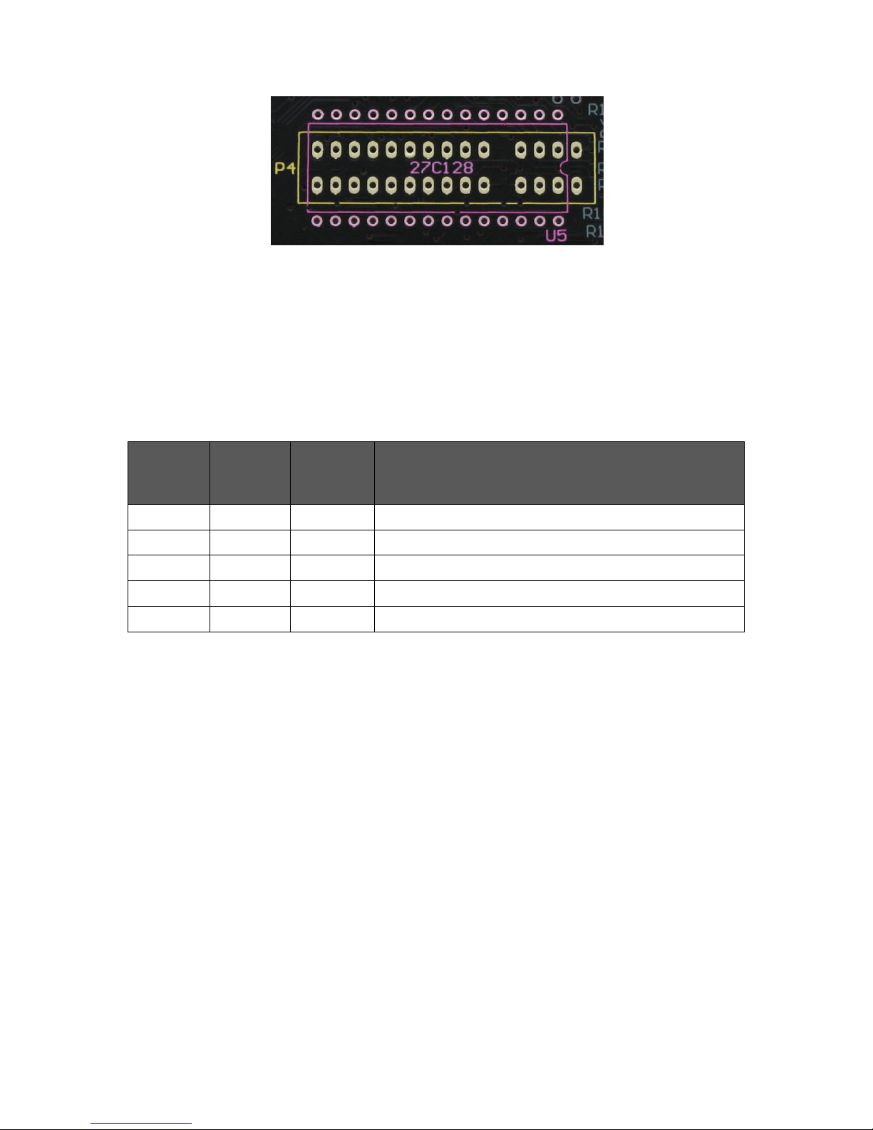
Chapter 7
60
Overlapping ROM socket footprints
The outline labelled U5 can be fitted with a 28-way DIL IC socket to allow an onboard
ROM to be used. The outline labelled P4 can be fitted with a 2 x 15-way edge
connector socket to allow the use of ZX Interface 2 ROM cartridges.
The table below summarises the different ROM modes supported by the SPECTRA
interface:
ROM
cartridge
present
Onboard
ROM
enabled
Paging
mode
enabled
Operating mode
No
No
Yes / No
Spectrum ROM permanently paged in
No
Yes
No
Onboard ROM permanently paged in
Yes
No
No
ROM cartridge permanently paged in
No
Yes
Yes
Onboard ROM paged in on ZX Interface 1 address
Yes
No
Yes
ROM cartridge paged in on ZX Interface 1 address
Summary of supported ROM modes
When an onboard ROM is not present, configuration switch 2 should always be set to
the off position. A ROM cartridge or an onboard ROM should only ever be inserted or
removed while the Spectrum is powered off, otherwise a crash will occur and damage
may result to the hardware. With an external ROM connected and enabled, it is the
state of configuration switch 3 that determines whether the Spectrum’s BASIC ROM
will be overridden or supplemented.
Overriding the Spectrum’s ROM
The Spectrum’s ROM can be overridden by setting configuration switch 3 to the off
position. The SPECTRA interface will automatically detect and enable a ROM cartridge
if one is plugged in, but to use an onboard ROM requires manually enabling it by
setting configuration switch 2 to the on position. Either form of external ROM will
remain enabled even after the Spectrum is reset. If an onboard ROM is fitted but
configuration switch 2 set to the off position then the onboard ROM is disabled and
will lie dormant. If a device connected behind the SPECTRA interface requests access
to the ROM address space then an onboard ROM or a plugged in ROM cartridge will
always be disabled.
Page 63

Chapter 7
61
Supplementing the Spectrum’s ROM
The Spectrum’s ROM can be supplemented to extend Sinclair BASIC with new
commands by setting configuration switch 3 to the on position. Either a ROM cartridge
must be plugged in or an onboard ROM enabled via configuration switch 2 being set
to the on position. In this mode, the paging mechanism implemented by the
ZX Interface 1 is reproduced by the SPECTRA interface. This paging mechanism
extends Sinclair BASIC by detecting when the BASIC ROM is about to display an error
report on the screen and passing control over to the ZX Interface 1 ROM so that it can
attempt to handle the command causing the error. Note that the ZX Interface 1 ROM is
also known as the Shadow ROM, with the Spectrum’s BASIC ROM then referred to as
the Main ROM.
The ZX Interface 1 intercepts the error handler routine within the BASIC ROM at
address $0008. Its hardware pages in the Shadow ROM after the first byte of the
instruction is read in, and so the remaining bytes of the instruction are fetched from the
Shadow ROM (which means that the instruction in the Shadow ROM must be same
as that in the Main ROM). Execution then continues using the Shadow ROM. Normally
the error handler routine would have displayed the appropriate error report message,
but now the Shadow ROM has the opportunity to analyse the cause of the error and to
determine whether it was due to the syntax of one of its new commands. If it was then
the corresponding command handler within the Shadow ROM is executed, otherwise
a return is made to the Main ROM so that the original error report message can be
displayed. After the new command handler has completed, a switch back to the Main
ROM is made via a call to address $0700. Fetching an instruction from this address is
detected by the hardware and it pages back to the Main ROM after a byte has been
read in (this limits the size of the instruction to a single byte). There is a RET instruction
at this location within the ZX Interface 1 ROM and so the call immediately returns but
now to a location within the Main ROM. The ZX Interface 1 paging mechanism also
intercepts an instruction fetch from address $1708, which is located midway through
the CLOSE# BASIC command handler. This is done because the command handler in
the BASIC ROM does not support the enhanced channel format introduced for the
new ZX Interface 1 facilities and so an alternate routine needed be used instead. The
Shadow ROM is paged in after the first byte of the instruction is read in and so the
Shadow ROM contains the same instruction at this address as the Main ROM
(although note that the instruction at this location happens to be only a single byte in
length).
Supplementing the Spectrum’s ROM using the ZX Interface 1 paging method has a
number of advantages. It allows a ZX Interface 1 fitted with the first edition ROM to be
effectively upgraded by overriding it with a newer version held in the external ROM of
the SPECTRA interface. The newer version could simply be a copy of the second
edition ZX Interface 1 ROM or could be a customised version that has all remaining
bugs fixed. You can tell if your ZX Interface 1 has a first edition ROM by typing PRINT
PEEK 23729, which will return a value of 0 with a first edition ROM and 80 with a
second edition ROM. Even if ZX Interface 1 hardware is not connected, it is still
possible to make some use of the new commands introduced by the ZX Interface 1
Page 64

Chapter 7
62
ROM. For instance, the extended BASIC can be used to control the SPECTRA
interface’s RS232 socket, and the new command CLS# (which resets the screen
colours) will operate successfully since it does not rely on the ZX Interface 1 hardware.
However, the most beneficial reason for using the ZX Interface 1 ROM is that it already
contains the necessary infrastructure to handle new BASIC commands and yet only
occupies half of the available ROM space (the ZX Interface 1 ROM is 8K in size
whereas the SPECTRA interface supports a 16K external ROM).
Should the external ROM be currently paged in at the moment that the Spectrum is
reset then it will be automatically be paged out. It will also be paged out when
configuration switch 2 is set to the off position and there is an onboard ROM fitted. If a
device connected behind the SPECTRA interface requests access to the ROM
address space then an onboard ROM or a plugged in ROM cartridge will always be
disabled.
Adding new BASIC commands
The process of creating new BASIC commands is well documented in Sinclair
literature due to the ZX Interface 1 ROM naturally providing a mechanism to extend
Sinclair BASIC. The mechanism requires the new commands to be run from RAM and
so they need to be loaded every time the Spectrum is reset. Having these commands
in ROM has the advantage that they are instantly available and do not take up
valuable RAM space. The process of hooking the commands into the parser of the
ZX Interface 1 ROM will be different but the approach used to examine the syntax of
the new commands can be the same. The operation of the ZX Interface 1 command
parser and examples of adding new BASIC commands are described in the Spectrum
Shadow ROM Disassembly book [4] and the Spectrum Micro Drive Book [7]. Another
useful reference is The Complete Spectrum ROM Disassembly book [8] as it will often
be necessary to make calls into the BASIC ROM. A commented assembly file of the
second edition ZX Interface 1 ROM is available from www.wearmouth.demon.co.uk [5]
and provides an ideal starting point for creating a customised version of the ROM. The
first place in this file to examine is the routine at location $01AA which is responsible
for identifying the token of the BASIC command that produced the syntax error that
caused the ZX Interface 1 ROM to be paged in. This routine could be patched to
perform checks for further tokens, or the command handlers that are currently called
could be patched to support alternate forms of those commands. Each patch should
change the existing ROM code as little as possible by simply redirecting program
execution into a continuation routine located within the additional 8K space. In this
way, all routine address entry points remain the same and so existing machine code
programs that directly rely on them will still function correctly.
Although it is possible to remove unwanted commands from the ZX Interface 1 ROM
to make additional space available, it is recommended to keep them in place so that
the enhanced ROM is fully backwards compatible with all existing programs.
Supporting the new attribute modes
One use for the additional 8K of space would be to add BASIC commands that select
and operate on the new attribute modes provided by the SPECTRA interface. However,
Page 65

Chapter 7
63
as mentioned in Chapter 4 the attribute files of the new display modes overlap with
the BASIC environment’s system variables and program listing area. This problem can
be partially overcome by shifting the BASIC program up in memory until it is beyond
the extent of the new attribute files, thereby creating a gap between the system
variables and the BASIC program area. This can be done by adjusting the Spectrum’s
system variables to create a region between the Channel Information area and the
BASIC program area (much in the same way that the ZX Interface 1 inserts its new
system variables after the standard ones). The region could be created upon the first
invocation of the external ROM, or once a new attribute mode has been selected. The
size of the region would need to be large enough for the selected attribute mode, and
could be dynamically adjusted when changing to a different attribute mode. An
alternate approach would be to simply create a region large enough to accommodate
all of the new attribute modes, but this would result in a less efficient use of memory.
Shifting the BASIC program would allow most of the new attribute modes to be
supported, except for all row and single line modes that use double byte colour since
their attribute files overlap the Spectrum’s system variables. The size of the region
required to shift the BASIC program area above the attributes file for each attribute
mode is shown in the following table.
Attribute mode
Region size
Lowest address of
BASIC area
Row mode, basic colours, single byte
$0000
$5D05
Row mode, basic colours, double byte
Mode not supported
Row mode, extra colours, single byte
$0000
$5D05
Row mode, extra colours, double byte
Mode not supported
Quad line mode, basic colours, single byte
$08FB
$6600
Quad line mode, basic colours, double byte
$10FB
$6E00
Quad line mode, extra colours, single byte
$08FB
$6600
Quad line mode, extra colours, double byte
$10FB
$6E00
Dual line mode, basic colours, single byte
$0EFB
$6C00
Dual line mode, basic colours, double byte
$1EFB
$7C00
Dual line mode, extra colours, single byte
$0EFB
$6C00
Dual line mode, extra colours, double byte
$1EFB
$7C00
Single line mode, basic colours, single byte
$1AFB
$7800
Single line mode, basic colours, double byte
Mode not supported
Single line mode, extra colours, single byte
$1AFB
$7800
Single line mode, extra colours, double byte
Mode not supported
Shifted BASIC area required for each attribute mode
Page 66

Chapter 7
64
These figures assume that the 58 bytes required for the ZX Interface 1 system
variables are also created. Note that the creation of Microdrive Maps and additional
Channel Information entries would further shift the BASIC program up in memory. This
would result in some wasted space but could only be avoided by further patching of
the ZX Interface 1 ROM.
The new BASIC commands required to operate the different display modes could
make use of the streams and channels mechanism built into the Spectrum by
introducing a new channel type, e.g. ‘D’. A stream could then be opened to this
channel using the OPEN keyword, e.g. OPEN #4;"D". Once opened, characters could
be sent to the stream using standard PRINT commands, e.g. PRINT #4;"SPECTRA". It
would be necessary to provide a way to select the active display mode and so a
command such as FORMAT "D";n could be used (where n would specify the mode
number). An enhanced version of the INPUT statement could be implemented to
operate with the active display mode, e.g. INPUT #4;"Enter your name";N$. Other
commands that operate on the screen could be implemented using syntax similar to
that introduced by the ZX Interface 1, i.e. by following a command keyword with a
symbol. The use of a symbol ensures that the statement fails the Spectrum’s standard
command parser, and so allows the Shadow ROM a chance to handle it. The
commands introduced by the ZX Interface 1 ROM use an asterisk for this purpose.
This works fine when used with commands SAVE, LOAD, VERIFY and MERGE, but if
used for new commands that expect a numeric parameter then the symbol could
appear to be a multiplication sign and might lead to confusion. Therefore, an alternate
symbol such as the percentage sign would a better choice. The new display modes
could then be controlled using a range of commands such as BORDER %, PAPER %,
INK %, FLASH %, CLS %, DRAW %, PLOT %, CIRCLE %, COPY %, etc.
Should the active display mode be set to the Spectrum’s standard screen format then
the new BASIC commands could simply delegate to the existing routines in the BASIC
ROM. New system variables might be required by the commands and so additional
entries could be inserted after the ZX Interface 1 system variables.
Page 67

CHAPTER 8
Chapter 8
CHAPTER
Page 68

Page 69

Chapter 8
67
Reset button and expansion bus
Reset button
The SPECTRA interface provides a button which allows the Spectrum to be reset
without the need for removing and re-inserting the power connector, thereby reducing
wear on the connector and the power socket. Momentarily pressing the button will
cause the Spectrum to reset.
Upon the Spectrum resetting, the following actions are performed:
The standard display mode is selected (the display mode register reset to $00).
The Comms_Out flag is cleared, thereby deselecting RS232 output mode.
The CTS and RX data output lines of the RS232 port are set to the off state.
The Spectrum’s ROM is paged back in if an external ROM is active and the BASIC
extension mode is enabled.
Rear expansion bus
The SPECTRA interface provides a full width rear expansion bus to allow further
devices to be attached behind it. The rear expansion bus contacts are gold plated to
prevent them tarnishing easily and therefore to improve the reliability of the electrical
connection.
The expansion bus contains all of the signals exposed by the Spectrum except for the
video related signals /Y, U, V, 0V
video
and VIDEO, which are used exclusively by the
SPECTRA interface to synchronise the TV picture it generates with that produced by
the Spectrum. The signals already contain a large amount of electrical noise and so
they are not passed through to the rear expansion bus to avoid further pickup of
interference, which might otherwise prevent the display synchronisation mechanism
working correctly.
The /IORQ line that appears on the rear expansion bus is not directly connected to
that output by the Spectrum. This is done to allow the SPECTRA interface to filter out
accesses to the display mode register when the additional display modes functionality
is enabled. This is required so that the SPECTRA interface can coexist with (most)
devices that also use a base IO address of $DF and also with Kempston joystick
interfaces that do not fully decode the joystick input port address. The SPECTRA
interface forces the /IORQ line exposed on its rear expansion bus to logic ’1’ whenever
an access to the display mode register occurs. This prevents devices connected
behind it from detecting, and therefore responding, to such accesses. This issue is
discussed in more depth in Appendix B.
When the additional display modes are disabled via configuration switch 6, the
SPECTRA interface simply passes all I/O requests through to the rear expansion bus
unfiltered, thereby achieving full I/O compatibility with all existing devices.
Page 70

Page 71

APPENDICES
APPENDICES
Page 72

Page 73

Appendix A
71
Power usage
The SPECTRA interface uses a sizeable amount of current, but the Spectrum power
supply is more than capable of handling this. However, if other peripherals are also
attached then care must be taken to ensure that the power supply’s current rating is
not exceeded.
The Spectrum power supply outputs a nominal 9Vdc and is capable of delivering 1.4A.
The table below shows typical current usage for the SPECTRA interface and the range
of official Spectrum peripherals when in operation. To find the total current usage,
simply sum up the figures for the appropriate devices. The result should be less than
1.4A to ensure safe and reliable operation. Note that the current used by a device can
vary based upon its state, and so the figures shown may actually be lower than the
peak values and should therefore only be used as a guide. The Spectrum power
supply will generate heat when in use, the temperature of which will be related to the
amount of current drawn from it, and if more current is drawn than the unit is specified
to handle then it could heat up to a level where it becomes a fire hazard. Should the
summed current usage be close to the 1.4A rating of the power supply, it may be wise
to disconnect a peripheral or replace the power supply with a higher rated unit.
Item
Current (mA)
48K ZX Spectrum
640
SPECTRA interface
280
ZX Interface 1
90
ZX Microdrive (each)
190
ZX Interface 2
40
ROM cartridge
20
ZX Printer
210
Typical current usage of Sinclair devices
The SPECTRA interface generates its own 5V supply rail from the raw 9V input from the
Spectrum power supply. This is done to reduce the loading placed on the Spectrum’s
internal 5V regulator and therefore to avoid additional heat being generated inside the
computer. However, the optional onboard ROM and ROM cartridge socket facilities are
powered from the Spectrum’s 5V supply rail. This is done to ensure that the current
draw of the SPECTRA interface remains reasonably constant irrespective of which
options are fitted. A DC-DC converter is used by the SPECTRA interface to generate its
5V supply rail, and this generates far less heat than the equivalent linear voltage
regulator (as used inside the Spectrum). By keeping the current draw restricted and
relatively constant the need for a heatsink is eliminated, and this helps keep the board
size to a minimum. Note that the DC-DC converter may still get hot and so care should
be taken not to touch it, or to prevent air circulation around it. The CPLD logic IC on the
SPECTRA interface is also likely to get hot and so should not be touched either.
Page 74

Page 75

Appendix B
73
Hardware compatibility
The SPECTRA interface provides various options to achieve compatibility with existing
Spectrum peripherals and software. Its RS232 port can be disabled to prevent a
conflict with a ZX Interface 1, and its joystick port can be disabled to prevent a conflict
with another device which already provides a Kempston joystick socket. Its new
display modes can also be disabled to ensure full I/O compatibility with all existing
peripherals and software.
As described in Chapter 4, the new display modes provided by the SPECTRA interface
are controlled using an I/O port. In theory there can be up to 65536 different input
ports and 65536 different output ports, but the range available on the Spectrum is
significantly less than this due to the use of partial address decoding. This method
causes a device to be selected when only a subset of address lines match a
particular pattern, and often Sinclair peripherals will check just one address line. For
example, the ZX Printer is selected whenever address line A2 is set to logic ’0’. This
means that no other device may use an I/O address in which line A2 is also at logic ’0’
otherwise a conflict will occur. The advantage of using partial address decoding is that
it reduces the amount of circuitry required and therefore lowers the cost of the device.
However, the disadvantage is that it dramatically reduces the number of usable I/O
addresses.
Some Spectrum manufacturers made matters worse by decoding I/O address $FF
(binary 11111111), which prevented other devices performing decoding on just the
high order address lines. As a result, peripheral manufacturers had soon used up all
non-conflicting I/O addresses, leaving no choice but for newer peripherals to duplicate
on addresses. This means that certain combinations of devices just cannot coexist
with each other.
The SPECTRA interface uses I/O port $7FDF (binary 01111111 11011111, decimal
32735) for both input and output to control its new display modes. It fully decodes all
address lines, thereby allowing other devices to use a base address of $DF and avoid
conflict by using different values for the high order address lines. However, devices
which just decode the base address $DF (binary 11011111) would clash. The
SPECTRA interface attempts to limit the number of such conflicting devices by
preventing display mode register accesses appearing on its rear expansion bus. It
does this by forcing the /IORQ line exposed on the rear expansion bus to logic ’1’
whenever an access to I/O address $7FDF occurs. Since devices connected behind
the SPECTRA interface are no longer able to detect such accesses, they cannot
respond to them. All other addresses which have a base of $DF are passed through,
and so a device will only fail to operate correctly should its software driver happen to
set the high order address lines to $7F during an I/O port operation (which is only one
out of the 256 possible values). If the device’s software driver does access I/O port
$7FDF then the only solutions left are to disconnect the device or to disable the new
display mode functionality via configuration switch 6.
Page 76

Appendix B
74
It is also possible for a conflict to occur with a device supposedly accessing a different
I/O port. As described in Chapter 5, the Kempston joystick socket uses input port $1F
(binary 00011111, decimal 31), and so it should only be read when address lines A5 to
A7 are all at logic ’0’. However, some interfaces (such as the RAM Turbo) only check
that address line A5 is at logic ’0’ and this causes a problem because the display
mode register I/O port happens to have address line A5 at logic ’0’. Since the
SPECTRA interface filters all display mode register accesses from its rear expansion
bus, connecting such a conflicting device behind it will overcome the problem.
The Snow Effect
When the Z80’s I register is set with a value between $40 and $7F, the TV image
produced by the Spectrum breaks-up, with pixels apparently being randomly set or
reset across the screen. This is referred to as the snow effect. It is caused as a result
of the Spectrum’s ULA failing to recognise a memory refreshes as a contention
condition with the Z80.
The Z80 has built-in refresh circuitry to simplify interfacing to dynamic memory. When
a refresh operation occurs, the contents of the Z80’s I register are placed on the high
order address lines and the contents of the R register are placed on the low order
address lines. Setting the I register with a value between $40 and $7F causes memory
refresh operations to occur within address range $4000 to $7FFF, which is where the
display and attribute files reside. The ULA should detect and prevent such memory
refreshes occurring when it is fetching a display byte by temporarily halting the Z80. Its
failure to do so results in a corrupted address appearing on the address bus and
hence the wrong byte fetched and displayed.
The SPECTRA interface attempts to replicate the snow effect but does not do so
accurately. This is because it contains static RAM and not dynamic RAM as used
inside the Spectrum, and the method of accessing this type of memory is sufficiently
different. Therefore the ‘snow’ produced by the SPECTRA interface is not identical to
that produced in the standard TV picture. Note that ‘snow’ can occur in any of the
attribute modes, and not just the standard one.
The cause of the snow effect is described in detail in The ZX Spectrum ULA book [1].
Page 77

Appendix C
75
Troubleshooting
This section provides a list of common problems and lists possible solutions. For
solutions suggesting the Spectrum is at fault, it is advisable to perform independent
tests to verify the cause before opting to replace components.
Symptom
Possible cause
Solution
No picture on the
TV and the video
signal absent
indicator is off.
1. The Spectrum is faulty.
Check that a picture is
received using the standard
‘TV’ socket of the Spectrum.
2. Dirty expansion bus
connections.
Remove dirt using an
electrical cleaning solvent
(some can damage plastic so
care must be taken).
4. SCART socket on TV does
not support an RGB
connection.
Consult TV manual. Try with all
SCART sockets on the TV.
4. SCART cable wiring not
suitable.
Check cable conforms to
wiring described in Chapter 3.
5. The Spectrum is not
generating a 12V signal.
Check that 12V appears on
the Spectrum’s expansion bus
at pin 22B.
No picture on the
TV and the video
signal absent
indicator is on.
1. Spectrum is an issue 1 or 2
and does not have the
internal video link fitted.
Solder in the video link. Refer
to Chapter 3 for details.
2. The Spectrum is a 128K
machine.
None. The SPECTRA interface
is not compatible with a 128K
Spectrum.
Cannot obtain the
new display modes
or read the display
mode register.
1. New display modes are
disabled.
Enable the new display
modes using configuration
switch 6.
2. Conflict with another
peripheral.
Attach each peripheral one at
a time to identify which is
conflicting. Try connecting the
peripherals behind the
SPECTRA interface.
Other peripheral not
working correctly.
1. Peripheral not properly
decoding its I/O port.
Connect peripheral behind the
SPECTRA interface.
2. Conflict with the new display
modes.
Disable new display modes
using configuration switch 6.
Page 78

Appendix C
76
Symptom
Possible cause
Solution
RS232 socket not
working.
1. Conflict with RS232 socket
of a ZX Interface 1.
Disable the RS232 socket on
the SPECTRA interface using
configuration switch 4 and
use ZX Interface 1 socket.
2. RS232 cable wiring not
suitable.
Check wiring is suitable for the
target device (see Chapter 6 for
wiring required to a PC).
Kempston joystick
not working.
Conflict with joystick socket of
another peripheral.
Disable the joystick socket on
the SPECTRA interface using
configuration switch 5 and
use other peripheral’s socket.
TV picture shifted to
the far left, or jumps
horizontally.
Using a flat screen Panasonic
TV.
None. Use another TV if
available. The problem is
caused by the Panasonic TV
incorrectly expecting a colour
burst signal to appear on the
composite sync line.
Picture is stretched
horizontally.
Using a widescreen TV that is
configured to automatically
stretch pictures having an
aspect ratio of 4:3.
Disable auto-stretch mode in
the TV.
Pixels have outlines
around them.
Using a TV that is applying
filtering to attempt to improve
the picture, e.g. sharpening,
motion smoothing.
Disable all filters in the TV
intended to improve the
picture quality.
Cannot extend
BASIC using an
external ROM when
paging mode is
enabled.
1. The onboard ROM is not
enabled.
Enable the onboard ROM
using configuration switch 2.
2. Dirty /M1 signal on the
expansion bus.
Remove dirt using an
electrical cleaning solvent
(some can damage plastic so
care must be taken).
3. The /M1 signal from the Z80
inside the Spectrum is faulty.
Replace Z80 CPU inside the
Spectrum. A /M1 fault can go
unnoticed since it is only used
by external devices, e.g.
SPECTRA or ZX Interface 1.
‘Snow’ appears on
screen all the time,
or does not appear
when expected.
The /RFSH signal from the Z80
inside the Spectrum is faulty.
Replace Z80 CPU inside the
Spectrum. A /RFSH fault can
go unnoticed since it is only
used by external devices.
Page 79

Appendix D
77
References
This section provides a list of useful reference books and websites.
[1] The ZX Spectrum ULA
By Chris Smith
2010, ZX Design and Media (www.zxdesign.info)
ISBN 978-0-9565071-0-5
[2] ZX Spectrum Microdrive and Interface 1 Manual
1983, Sinclair Research Ltd
[3] Your Spectrum
“new rom antics” by Andrew Pennell
Issue 18, September 1985, page 27
Sportscene Specialist Press Ltd
[4] Spectrum Shadow ROM Disassembly
By Gianluca Carri
1985, Melbourne House (Publishers) UK
ISBN 0-86161-191-8
[5] www.wearmouth.demon.co.uk
By Geoff Wearmouth
Online commented assembly files of ZX Spectrum and ZX Interface 1 ROMs
[6] ZX Resource Centre
By Paul Farrow
www.fruitcake.plus.com / www.zxresourcecentre.co.uk
Documents retail, unreleased and custom ZX Interface 2 ROM cartridges
[7] Spectrum Micro Drive Book
By Dr. Ian Logan
1983, Melbourne House (Publishers) UK
ISBN 0-86759-127-6
[8] The Complete Spectrum ROM Disassembly
By Dr. Ian Logan & Dr. Frank O’Hara
1983, Melbourne House (Publishers) UK
ISBN 0-86161-116-0
Page 80

Page 81

Page 82

Paul Farrow
www.fruitcake.plus.com
www.zxresourcecentre.co.uk
 Loading...