

Page 1
AIR TO WATER HEAT PUMPS
MONOBLOCK INVERTER
SMH-100IRA
SMH-140IRA
Page 2

“Originalinstructions”
Page 3

Notices
Do not install the control where it is damp or exposed to direct sunlight.
Once the air conditioning unit is installed where possibly subject to electromagnetic interference,
shielded twisted pairs should be used as signal lines and other communication lines.
Be sure communication lines are wired to the correct ports, or normal communication would fail.
Do not beat, toss or frequently assemble and disassemble this control.
Do not operate the control with wet hands!
Figures in this Manual are just for reference!
We the manufacturers keep the right to modify this Manual owing to sales or other production
reasons without previous notice.
Page 4

Contents
1. External View ..........................................................................................1
1.1 Keys & Indicating LEDs .............................................................................. 1
1.2 Standby Page and Homepage .................................................................... 2
2. Operation Instructions ............................................................................3
2.1 On/Off .......................................................................................................... 3
2.2 Function Setting .......................................................................................... 4
2.3 Parameter Setting (Parameter Set) .......................................................... 22
2.4 View .......................................................................................................... 24
2.5 General Setting ......................................................................................... 29
2.6 Key Lock ................................................................................................... 30
Page 5
Operation Instructions
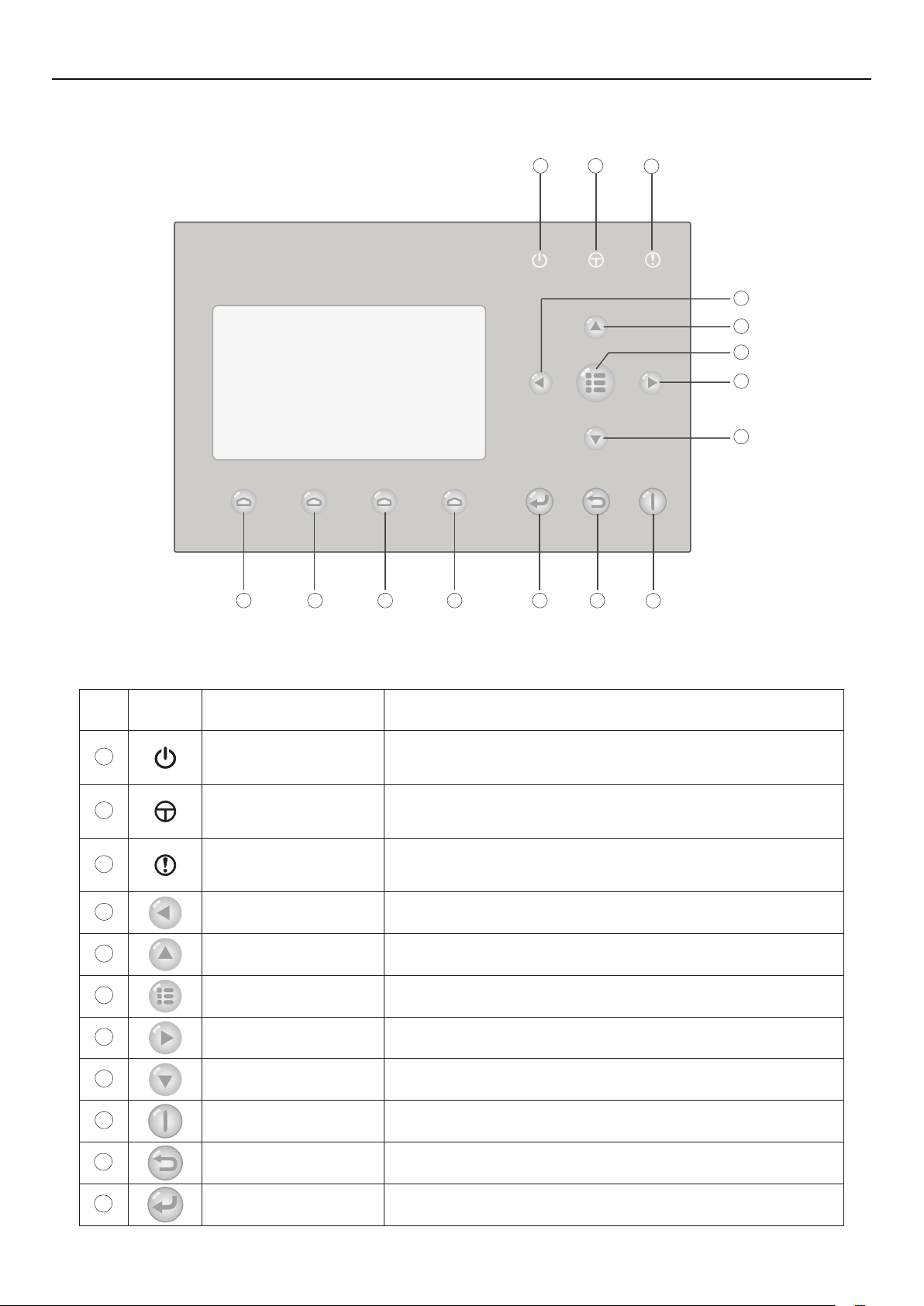
1. External View
1 2
3
4
5
6
7
8
101112131415
9
(This effect drawing is just for reference)
1.1 Keys & Indicating LEDs
No. Symbol Name Functional Description
1
2
3
4
5
6
7
8
Running indicating LED
(green)
Power indicating LED
(yellow)
Error indicating LED
(red)
Left key It is intended to move the cursor left.
Up key
Menu key It is intended to call out the main menu or back to the homepage.
Right key It is intended to move the cursor right.
Down key
It will light on/off when the unit is turned on/off.
It will light on/off when the unit is powered on/off.
It will light on when some fault occurs.
It is intended to modify the setting state or value of the selected
parameter.
It is intended to modify the setting state or value of the selected
parameter.
10
11
9
ON/OFF key It is intended to turn on or off the unit.
Cancel/Return key It is intended to go to the higher level menu.
OK key It is intended to save the setting or go to the submenu.
1
Page 6
Operation Instructions
12
13
14
15
Function key no. 4
Function key no. 3
It is intended to perform different functions at difference pages.
Function key no. 2
Function key no. 1
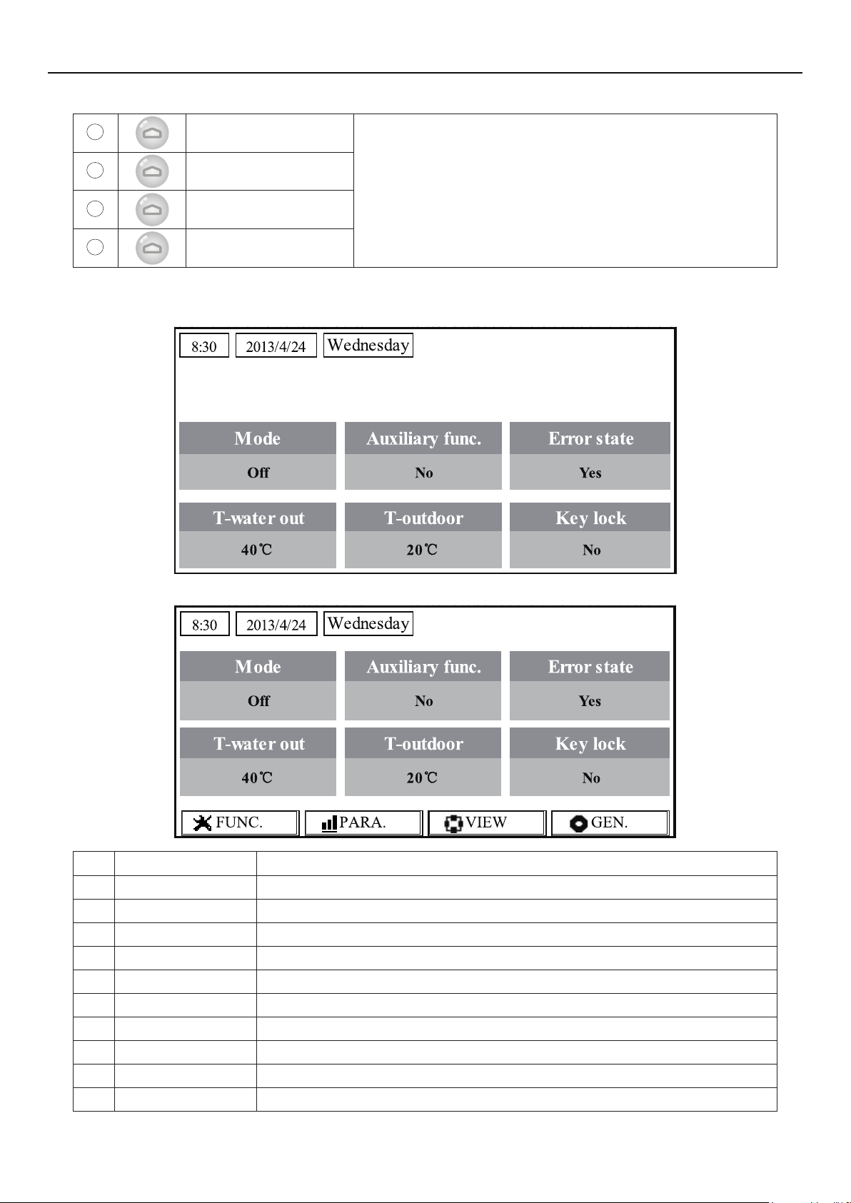
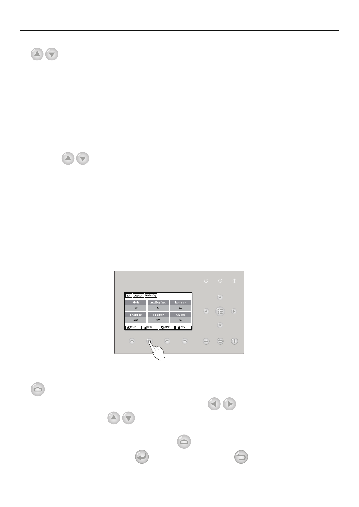
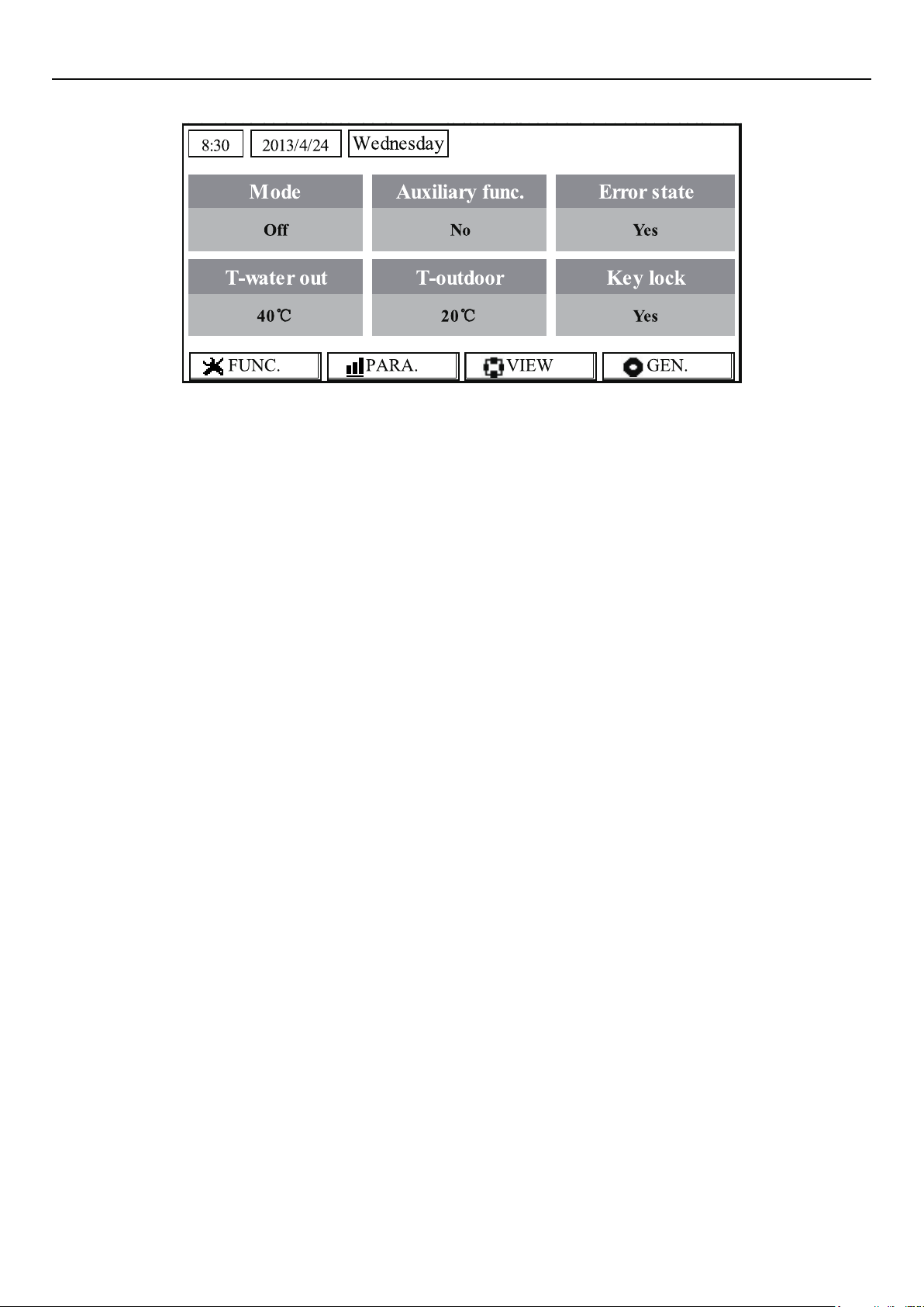
1.2 Standby Page and Homepage
Standby Page
Home Page
No. Item Functional Description
1 Mode It is intended to access to the actual running mode.
2 Auxiliary Func. It indicates the auxiliary function.
3 Error state It indicates if there is any error.
4 T-water out It indicates the actual leaving water temperature.
5 T-outdoor It indicates the actual outdoor environment temperature.
6 Key lock It indicates if the key lock is activated or deactivated.
7 FUNC. It is intended to access to the function setting page.
8 PARA. It is intended to access to the parameter setting page.
9 VIEW It is intended to access to the view page.
10 GEN. It is intended to access to the general setting page.
2
Page 7
Operation Instructions
Note:
it includes the “Sanitize mode”, “Quiet” mode, “Auto” mode, “Floor debug” mode, “Emergen.
mode”, “Holiday mode”, “Forced Cooling” mode, “Forced Heating” mode, and “Debug” mode.
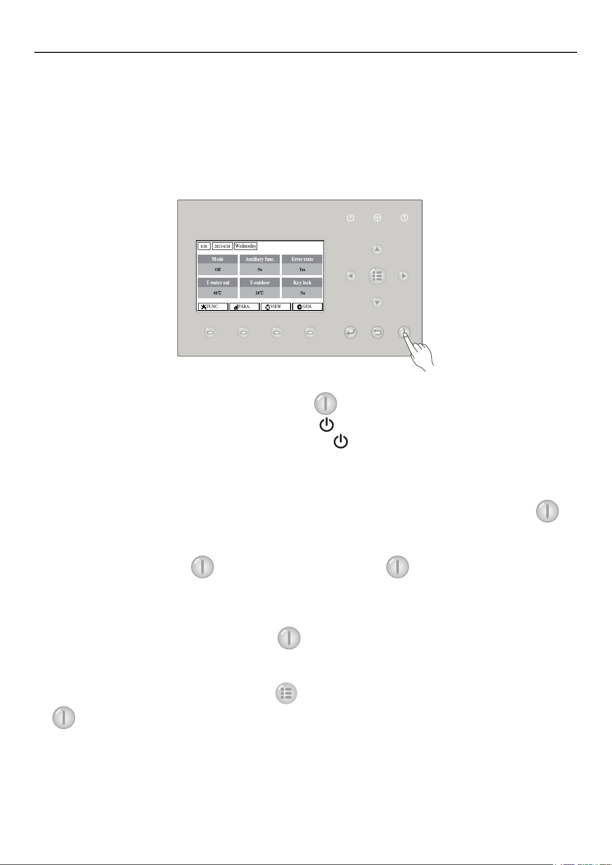
2. Operation Instructions
2.1 On/Off
It is intended to turn on/off the unit.
[Operation Instructions]
At the homepage, by pressing the ON/OFF key , the unit will be turned on/off.
When the unit is ON, the green indicating LED
light on. When the unit is OFF, the green indicating LED
[Notes]
The unit is defaulted to be OFF when energized for the rst time.
①
The ON/OFF key operation works only at the home page and the standby page.
②
When the “Holiday mode” or the “Emergen.mode” is activated, the ON/OFF key
③
operation will become ineffective.
When the “Forced Heating” or “Forced Cooling” is activated, it will be deactivated by
④
pressing the “ON/OFF” key
ON/OFF operation will be memorized by setting “Memory” to be “On” at the “GEN.” setting
⑤
page. That is, in case of power failure the unit will resume running upon power recovery. Once “On/
off Memory” is set to be “Off”, in case of power failure the unit will keep “Off” upon power recovery.
At the home page, the ON/OFF key
⑥
Function keys no.1 to no.4 are corresponding to “FUNC.”, “PAPA”, “VIEW” and “GEN.” setting pages
respectively.
, and then press the ON/OFF key
located at the upper right of the control will
will light off.
again to start the unit.
is intended to turn on/off the unit if applicable. The
At the standby page, the Menu key
⑦
is used to turn on/off the unit if applicable, and all other key operations are ineffective.
The control will return automatically to the homepage where there is no any key operation in
⑧
10 consecutive minutes.
is used to back to the homepage, the ON/OFF key
3
Page 8
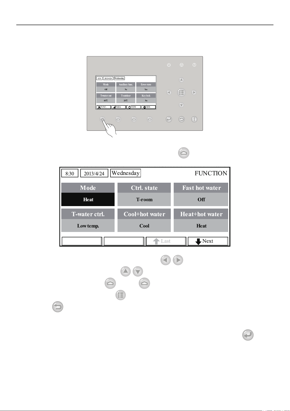
2.2 Function Setting
It enables the user to set each function.
[Operation Instructions]
Operation Instructions
1. At the homepage, by pressing the Function key no. 1
FUNCTION page 1, as shown in the gure below.
FUNCTION page 1
2. At the FUNCTION page, by the Right/Left key
be selected, and by the Up/Down key
modied. The function key no. 3
or no. 4 can be used for switch pages. After the setting
, the setting of the current function option can be
, the control will access to the
, the desired function option can
is nished, by pressing the Menu key
Return key
[Notes]
Move the cursor to the desired option and “Enter” will be displayed at the lower left side of the
①
LCD, reminding you that you are allowed to access to the submenu by pressing the OK key
At the FUNCTION page, when the setting of some function option is changed and needs to
②
be memorized, then in case of power failure it will be saved automatically and resume upon power
recovery.
the control will back to the higher level menu.
, the control will back to the homepage, or by pressing the
.
4
Page 9
Operation Instructions
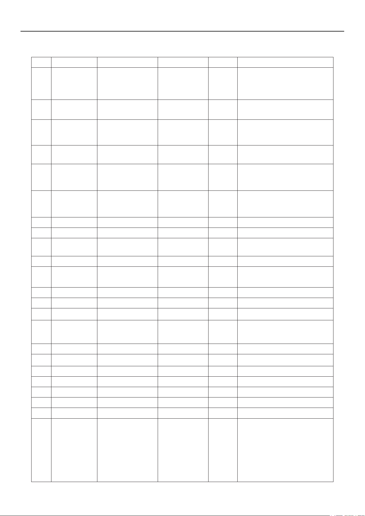
Function Settings
No. Full Name Displayed Name Range Default Remarks
1
Running mode
setting
Mode
Cool
Heat
Hot water
Cool+Hot water
Heat+Hot water
Heat
When the water tank is unavailable,
then only “Cool” and “Heat” are
included in the range.
2 Control state Ctrl. state
3 Fast hot water Fast hot water On/Off Off
4
5 Cool+hot water Cool+hot water Cool/Hot water Cool
6 Heat+hot water Heat+hot water Heat/Hot water Heat
7 Quiet mode Quiet mode On/Off Off /
8 Quiet timer Quiet timer On/Off Off /
9
10 Holiday release Holiday release On/Off Off /
11 Disinfection Disinfection On/Off Off
12 Weekly timer Weekly timer On/Off Off /
Water out
temperature
control
Weather-
dependent
mode
T-water ctrl.
Weatherdepend On/Off Off /
T-water out /
T-room
High temp.
/Normal temp.
T-water
out
Normal
temp.
“T-Room” is available only when
“Remote Sensor” is set to “WITH”.
When the water tank is unavailable,
this function will be reserved, and
the LCD will display ‘Reserved’.
/
When the water tank is unavailable,
this function will be reserved, and
the LCD will display ‘Reserved’.
When the water tank is unavailable,
this function will be reserved, and
the LCD will display ‘Reserved’.
When the water tank is unavailable,
this function will be reserved, and
the LCD will display ‘Reserved’.
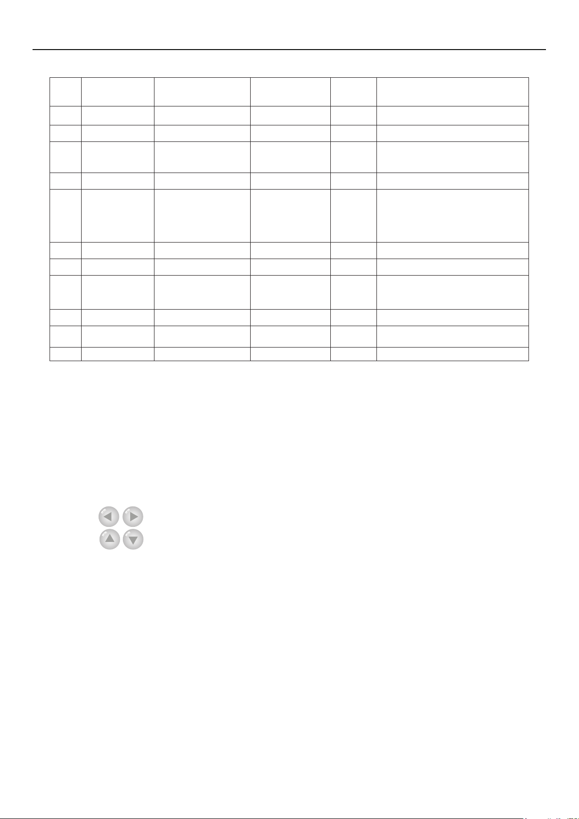
13 Clock timer Clock timer On/Off Off /
14
15 Solar kit-timer Solar timer On/Off Off
16 Floor debug Floor debug On/Off Off /
17
18 Holiday mode Holiday mode On/Off Off /
19 Thermostat Thermostat With/Without Without /
20 Assistant heater Assistant heater 1/2/Off 1 /
21 Other heater Other heater With/Without Without /
22 Chassis heater Chassis heater On/Off On /
23
Temperature
timer
Emergency
mode
Tank heater
running
Temp. timer On/Off Off /
Emergen. mode On/Off Off /
Tank heater On/Off On
When the water tank is unavailable,
this function will be reserved, and
the LCD will display ‘Reserved’.
If the water tank is available, this
function can be congured; if not,
this function will be reserved. When
“Tank heater” is set to be “Off”
but the solar kit is available, the
tank temperature can be adjusted
normally; when “Tank heater” is “Off”
and the solar kit is unavailable, then
the upper limit of tank temperature
is xed to be 50°C.
5
Page 10
Operation Instructions
24
25
26 Water tank Water tank With/Without Without /
27 Tank sensor Tank sensor 1/2 2
28 Solar heater Solar heater With/Without Without /
29 Floor cong Floor cong With/Without Off
30 Radiator cong Radia cong With/Without Off
31 FCU FCU With/Without Without
32 Remote sensor Remote sensor With/Without Without
33 Air removal Air removal On/Off Off /
34 Address Address
35 Gate-Controller Gate-Controller On/Off Off /
Plate heat
exchanger
heater
Solar kit-
antifreeze
Plate heater On/Off On
Solar antifre On/Off Off
[0~12]
[127~253]
0 /
When the water tank is unavailable,
this function will be reserved. and
the LCD will display ‘Reserved’.
If “Floor cong” is set to “With”, the
control is defaulted to be “Normal
temp”. If not, then the control is
defaulted to be “High temp”.
When it is set to “Without”, the
“Control state” will be automatically
changed to “T-water out”.
2.2.1 Mode
It enables the user to select the run mode of the unit. When the water tank is not prepared, then
only Cool and Heat modes are available. When the water tank has been prepared and Water Tank is
set to “With” through the wired controller (see Section 2.2.26 for more details), then Cool, Heat, Hot
water, Heat + hot water, and Cool + hot water modes are available. In this case, Heat + hot water
or Cool + hot water can be given priority. (see Section 2.2.5 and 2.2.6 for more details), which is the
default setting before delivery.
[Operation Instructions]
At the equipment OFF state, access to the FUNCTION page and then move through the Left/
Right key
Down key
[Notes]
The “Heat” mode is defaulted when the unit is energized for the rst time.
①
The running mode is allowed to be changed only when the unit is not in operation. If it is done
②
with the unit being on, a window will pop up, warning “Please turn off the system rst”.
When the water tank is disabled, only the ‘Heat” or the “Cool” mode is allowed.
③
When the water tank is enabled, “Cool”, “Heat”, “Hot water”, “Cool+hot waterr”, “Heat+hot
④
water” is allowed.
For the heat pump, the “Cool” mode is allowed; for the heating only unit, “Cool+ Hot water”
⑤
and “Cool” are unallowable.
This setting can be memorized upon power failure.
⑥
the cursor to the “Mode” whose characters will be reversed, then press the Up/
to modify its setting.
2.2.2 Control State (Ctrl. state)
It enables the user to configure the control state to leaving water temperature or room
temperature.
[Operation Instructions]
6
Page 11
Operation Instructions
Go to the FUNCTION page and locate Ctrl. state, then, congure it through the Up/Down key
.
[Notes]
If “Remote sensor” is set to “With”, “T-out water” and “T-room” are available. While if
①
“Remote Sensor” is set to “Without”, only “T-out water” is selectable.
This setting will be memorized upon power failure.
②
2.2.3 Fast Hot Water
When hot water is needed urgently, this function can be congured to be “On”, In this case, the
heat pump and the water tank heater will work together to generate sanitary hot water in a quickest
way.
[Operation Instructions]
Go to the FUNCTION page and locate “Fast hot water”, then, congure it through the Up/Down
key
[Notes]
, “On” or “Off”.
It works only when “Water tank” is set to “With”.
①
This setting will be memorized upon power failure.
②
2.2.4 T-water Ctrl (Water Temperature Control for Heating)
There are two options for the leaving water temperature control, high-temperature water
circulation (High temp) and normal-temperature water circulation (Normal temp). When “Floor
cong” is set to “With” (see 2.2.29), then the leaving water temperature control is defaulted to be
“Normal temp”. When “FCU cong”(see 2.2.31) or “Radia cong”(see 2.2.30) is set to“With”, the
leaving water temperature can be congured to either “High temp” or “Normal temp”.
[Notes]
“Floor cong”, “FCU cong”, and “Radia cong” all can be congured to be “With”. However,
as long as “Floor cong” is congure to be “With”, only “Normal temp” is available.
[Operation Instructions]
Go to the FUNCTION page and locate “T-water ctrl.”, then, congure it through the Up/Down
key
[Notes]
①
, “High temp.” or “Low temp.”.
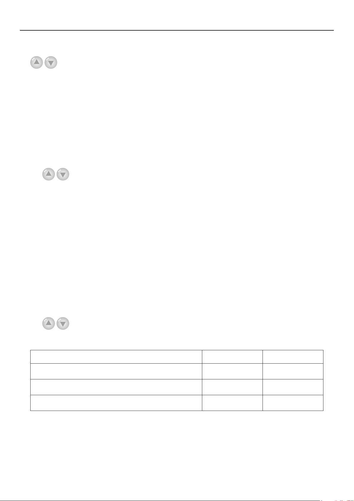
When this setting is changed, the following parameters will return to the default values.
Full Name Displayed Name Default
Water out temperature for heating WOT-Heat
Upper limit water-out temperature at the weather-dependent
mode for heating
Lower limit water-out temperature at the weather-dependent
mode for heating
This setting will be memorized upon power failure.
②
Upper WT-Heat
Lower WT-Heat
45°C/113°F[High]
35°C/95°F[Normal]
61°C/142°F[High]
35°C/95°F[Normal]
55°C/131°F[High]
29°C/84°F[Normal]
2.2.5 Cool + Hot water
This compound mode enables the user to give priority to the “Cool” or “Hot water” mode
depending on the actual demand.
[Operation Instructions]
7
Page 12

Operation Instructions
Go to the FUNCTION page and locate “Cool+hot water”, then, congure it through the Up/Down
key
[Notes]
“Reserved”.
, “Cool” or “Hot water”.
“Hot water” will take precedence only when “Water tank” is available, other it will tell
①
This setting will be memorized upon power failure.
②
2.2.6 Heat + Hot water
This compound mode enables the user to give priority to the “Heat” or “Hot water” mode
depending on the actual demand.
[Operation Instructions]
Go to the FUNCTION page and locate Heat+hot water, then, congure it through the Up/Down
key
[Notes]
①
“Reserved”.
②
, “Heat” or “Hot water”.
“Hot water” will take precedence only when “Water tank” is available, other it will tell
This setting will be memorized upon power failure.
2.2.7 Quiet
This function can be activated when the running noise is too high.
[Note]
when this function is activated, frequency of both the compressor and the fan will go down and
also the capacity of the unit will correspondingly decrease.
[Operation Instructions]
Go to the FUNCTION page and locate “Quiet”, then, congure it through the Up/Down key
, “On” or “Off”.
[Notes]
It can be set to “On” or “Off” no matter if the unit is in operation or not.
①
Once it is activated, it should be deactivated manually or by Quiet Timer.
②
This setting will be memorized upon power failure.
③
It will be deactivated when the unit is turned off.
④
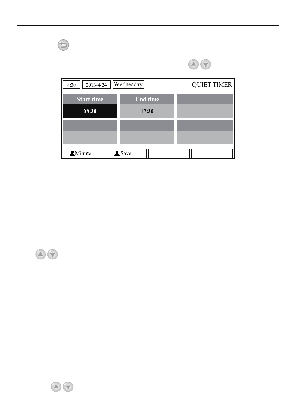
2.2.8 Quiet Timer
When running noise is too high at some specic timer period, this function enables the unit run
quietly at this time period.
[Operation Instructions]
1. Go to the FUNCTION page and locate Quiet timer, then, access to the QUIET TIMER setting
page.
2. At the QUIET TIMER setting page, select “Start time” or “End time” through the Left/Right
keys
remind if you are determined to save this setting. If so, press the “OK” key . If not, press the
and then congure the desired time through the Up/Down keys
3. When the mode setting is nished, then by pressing “Save”, a pop-up window will pop up to
.
8
Page 13
Operation Instructions
“Cancel” key
4. When the setting is saved, the control then will back to the FUNCTION page and the cursor
will be where the “Quiet timer” option is, then by the Up/Down key
or “Off”.
[Notes]
Once it is activated, it should be deactivated manually.
①
This setting will be memorized upon power failure.
②
The saved “Start time” and “End time” will be memorized upon power failure.
③
It is congurable no matter if the unit is in operation or not.
④
to not save this setting.
, it can be set to be “On”
2.2.9 Weather-dependent Mode
For areas with large change of diurnal temperature, in order to avoid the user to set the leaving
water temperature or room temperature too often, this function will adjust automatically depending on
the environmental temperature.
[Operation Instructions]
Go to the FUNCTION page and locate Weatherdepend, then, congure it through the Up/Down
key
[Notes]
Mode.
effective. However, when it is deactivated, the unit will run according to this set point.
when the unit is in operation.
, “On” or “Off”.
Once it is activated, it should be deactivated manually.
①
This setting will be memorized upon power failure.
②
At the “Parameter View” page, it is able to check the set point at the Weather-dependent
③
When it is activated, it is allowed to set the room temperature but the set point does not take
④
It can be set to “On” or “Off” no matter if the unit is in operation or not, but be activated only
⑤
This mode works only for the air conditioning function.
⑥
2.2.10 Holiday Release
In summer or high-temperature season, this function will make the unit pause to run in some
specic periods when the user is out.
[Operation Instructions]
Go to the FUNCTION page and locate “Holiday release”, then, configure it through the Up/
Down key
, “On” or “Off”.
9
Page 14
Operation Instructions
[Notes]
When it is activated, at the WEEKLY TIMER page, it is able to set some week day to “Holiday
①
release”. In this case, the “Weekly timer” in this day is ineffective unless it is set to “Effective”
manually.
This setting will be memorized upon power failure.
②
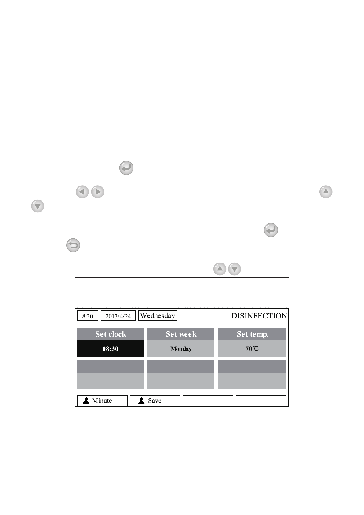
2.2.11 Disinfection
This function is intended to sanitize the water tank by raising the water temperature to 70°C
under which the legionella will die immediately. When this function is activated, the sanitation data
and start time is congurable.
[Operation Instructions]
1. At the FUNCTION page, locate “Disinfection”, and then access to the DISINFECTION setting
page by pressing the OK key
2. At the DISINFECTION setting page, select “Set clock”, “Set week” or “Set temp” through the
.
Left/Right key
and then modify the corresponding setting through the Up/Down key
.
3. When the mode setting is finished, then by pressing “Save”, a pop-up window will pop up
to remind if you are determined to save this setting. If so, press the OK key
Cancel key
to not save this setting.
. If not, press the
4. When the setting is saved, the control then will back to the FUNCTION page and the cursor
will be where the “Disinfection” is, then by the Up/Down key
Name Name Default Range
Disinfection temperature Set temp. 70°C 45°C~70°C
, it can be set to “On” or “Off”.
[Notes]
It can be activated only when the “Water tank” is set to “With”.
①
It can be set to “On” or “Off” no matter if the unit is in operation or not
②
When “Disinfection” is set to “On”, if you intend to set the “Emergen. mode”, “Holiday
③
mode”, “Floor Debug”, then a window will pop up, warning “Please disable the Disinfection
Mode!”.
It can be set to “On” or “Off” no matter if the unit is in operation or not, and “Hot water” mode
④
always takes precedence.
10
Page 15
Operation Instructions
When Sanitize is activated, “Disinfection” will show on the home page of the control until
⑤
this operation is nished. If this operation fails, “Disinfect fail” will show. In this case, by pressing any
key, “Disinfect fail” will be cleared or it will be always there.
When Sanitize is activated, it will quit upon “Communication error with the indoor unit” or
⑥
“Water tank heater error”.
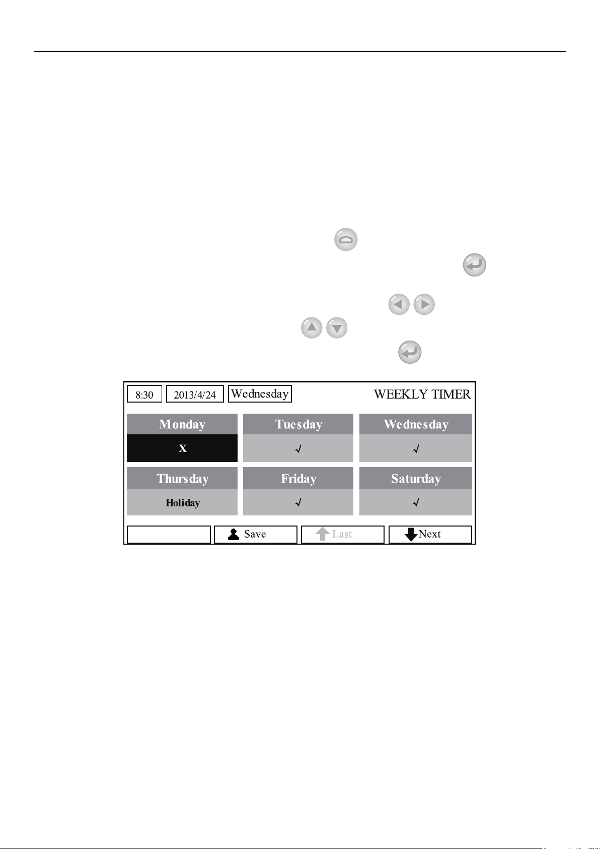
2.2.12 Weekly Timer
This function will make the unit run with certain modes in certain periods within a week based on
the user’s actual demand.
[Operation Instructions]
1. At the homepage, by pressing the Function key
then locate where “Weekly timer” is by switching pages, after that, press OK key
WEEKLY TIMER setting page.
2. At the WEEKLY TIMER setting page, by the Right/Left key
desired week day and then by the Up/Down key
shown in the gure below. When this setting is nished, press OK key
page.
access to the FUNCTION page, and
it is able to select the
to set this day, “√”, “×” or “Holiday”, as
to go to this day’s setting
to go to the
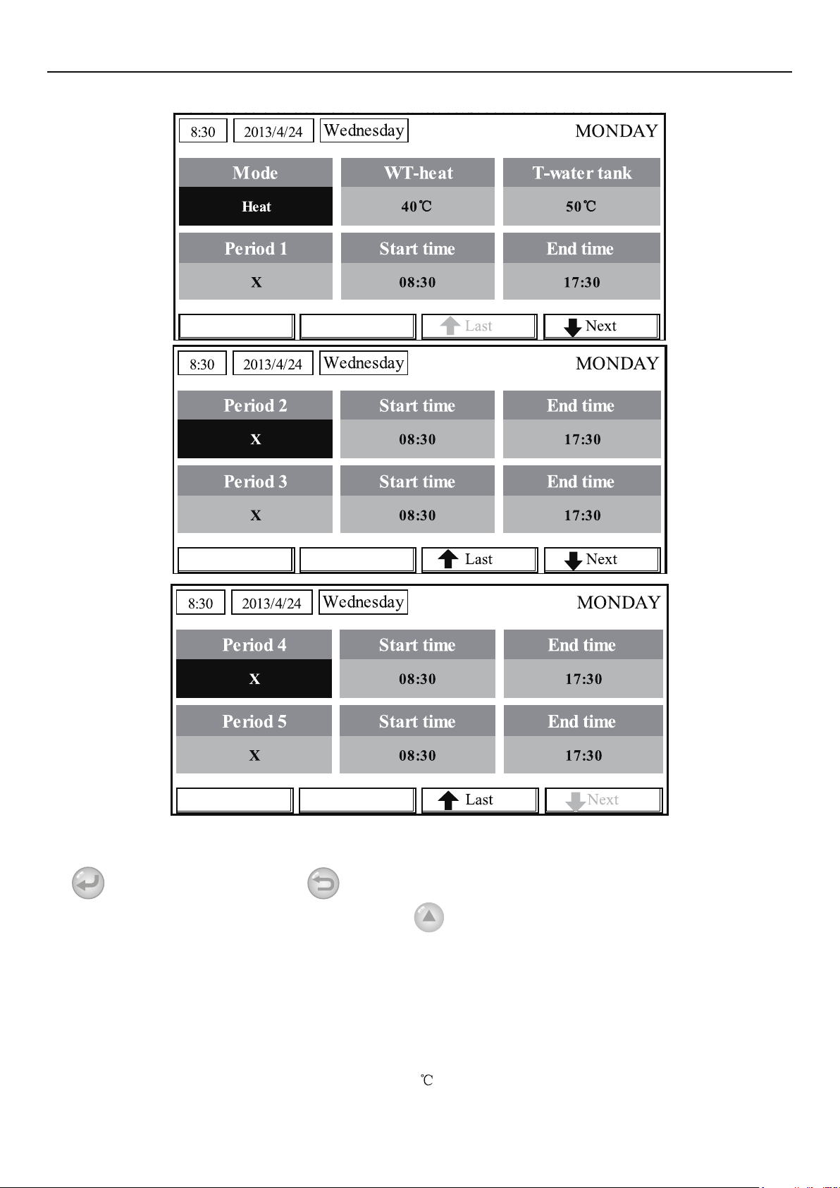
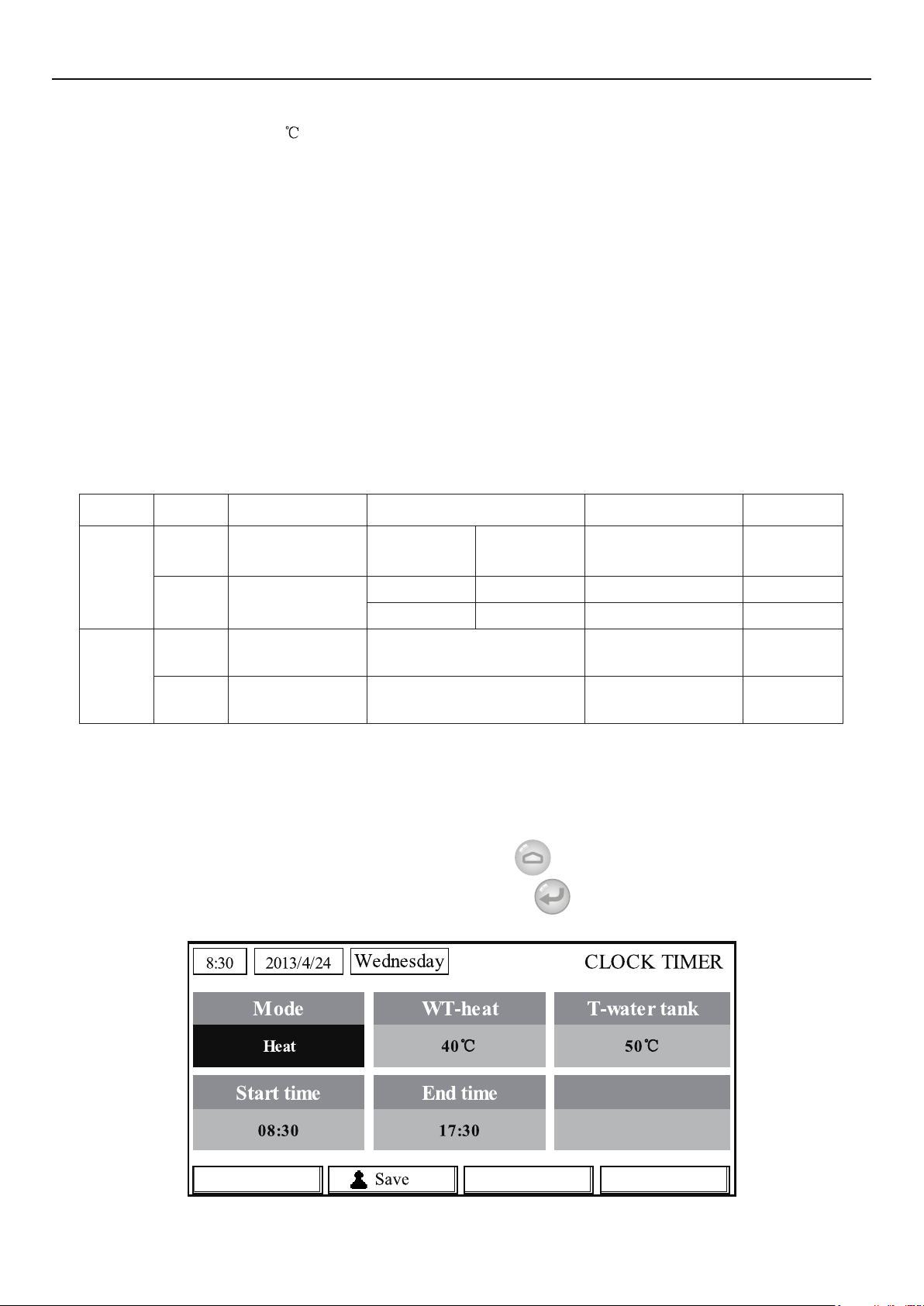
3. At the week day’s setting page, it is allowed to set the running mode (Mode), temperature set
point (WT-HEAT), and water tank temperature (T-Water Tank). The running mode includes “Heat”,
“Cool”, “Hot water”, “Heat+ hot water”, “Cool+ hot water” (the last three ones are available only
when “Water tank” is set to “With”. There are totally ve periods for each day, and each period can be
set to “√”or “×”. Besides, it is able to set the “Start time” and “End time” for each period, as shown in
the gure below.
11
Page 16
Operation Instructions
4. When above settings are nished, pressing the Return key and then pressing “Save”, a pop-
up window will pop up to remind if you are determined to save these settings. If so, press the OK key
. If not, press the Return key to not save these settings.
5. In this case, nally by pressing the Up key
[Notes]
Totally ve periods are allowed to be set for each time. For each period, “Start time” must be
①
earlier than “End time”. Similarly, the preceding period must be earlier than its following period.
When “Weekly timer” has been set successfully, by changing “FCU”, “Water tank”, “Ctrl
②
state”, or “T-water ctrl”, then the temperature set point for “Weekly timer” will be automatically
changed to the set point of last setting. For instance, if “Heat” is set for Monday of “Weekly timer”,
“FCU” is set to “With” and the “T-water out” is 20
out” will be the value of last setting. In this case, if FCU is disabled for last setting, then “T-water out”
, “Weekly timer” will be activated.
, by resetting “FCU” to “Without”, then “T-water
12
Page 17
Operation Instructions
will be the default value (18 ).
At the “WEEKLY TIMER” setting page there are totally three setting types for each day
③
“√”: it indicates once the Week Timer is activated, the timer on this day is effective and will not be
affected by the “Holiday” mode.
“×”: it indicates even if the Week Timer is activated, the timer on this day is ineffective.
“Holiday”: it indicates when the Week Timer is activated but “Holiday” is not activated, then the
timer on this day is effective; when “Holiday” is also activated, the timer on this day is ineffective.
When “Weekly timer” has already been set and the concerned modes include “Hot water”,
④
if resetting “Water tank” from “With” to “Without”, then “Hot water” mode will be automatically
changed to “Heat”, “Cool+hot water”/ “Heat+hot water” changed to “Cool”/ “Heat”.
Temperature Setpoint
⑤
The control is able to decide the temperature type and temperature range based on the current
“Clock Timer”, “FCU”, “T-water Ctrl.”, and “Ctrl. state” settings. See the followings for more details.
If the set mode is “Hot water”, the temperature set point shows nothing, indicating there is no
need to set “T-water out” and “T-room” but only “T- tank”. If the set mode “Cool” or “Heat”, then
water tank temperature box will show nothing, indicating there is no need to set “T-tank”.
Ctrl.
state
T-water
out
T-room
Set
Mode
Cool
Heat
Cool
Heat
Object Range Default Accuracy
Water out
temperature for
cooling(WT-cool)
Water out
temperature for
heating(WT-heat)
Room
temperature for
cooling(RT-cool)
Room
temperature for
heating(RT-heat)
7-25°C
(With FCU)
High temp. 25-61°C 45°C 1°C
Low temp. 25-55°C 35°C 1°C
18-30°C 24°C 1°C
18-30°C 20°C 1°C
18-25°C
(Without
FCU)
7°C(With FCU)
18°C(Without FCU)
1°C
2.2.13 Clock Timer
This function will make the unit run with certain modes in certain periods within a day based on
the user’s actual demand.
[Operation Instructions]
1. At the homepage, by pressing the Function key
then locate where “Clock timer” is, after that, press OK key
page.
access to the FUNCTION page, and
to go to the COLCK TIMER setting
13
Page 18
Operation Instructions
2. At the CLOCK TIMER setting page, by the Left/Right key
parameter and then by the Up/Down key
congure it.
select the desired
3. When this setting is concerned about time value, by pressing the Function key no. 1
alternately set the hour or minute values, and by pressing the Up/Down key
increase or
decrease the corresponding value which will be continuously changed by pressing and holding the
key. (Unless otherwise specied, all timer settings follow the similar way.)
4. When the setting is nished, save it by pressing the Function key no. 2
, or this setting
without being saved is ineffective.
5. When the setting has been saved, activate the “Clock Timer” at the FUNCTION page.
[Notes]
When “Weekly timer” and “Clock timer” settings are performed at the same time, the latter
①
takes precedence.
When the water tank is available, the allowed running modes include “Heat”, “Cool”, “Heat+
②
hot water”, “Cool+hot water”, and “Hot water”.
When the water tank is unavailable, the allowed running modes only include “Heat” and
③
“Cool”.
When “Clock timer” has already been set and the concerned modes include “Hot water”,
④
if resetting “Water tank” from “With” to “Without”, then “Hot water” mode will be automatically
changed to “Heat”, “Cool+hot water”/ “Heat+hot water” changed to “Cool”/ “Heat”.
2.2.14 Temp. Timer
This function will make the unit run with certain temperature in a certain period within a day
based on the user’s actual demand.
[Operation Instructions]
1. At the homepage, by pressing the Function key
locate where “Temp timer” is, after that, press OK key
access to the FUNCTION page, and then
to go to the TEMP TIMER setting page.
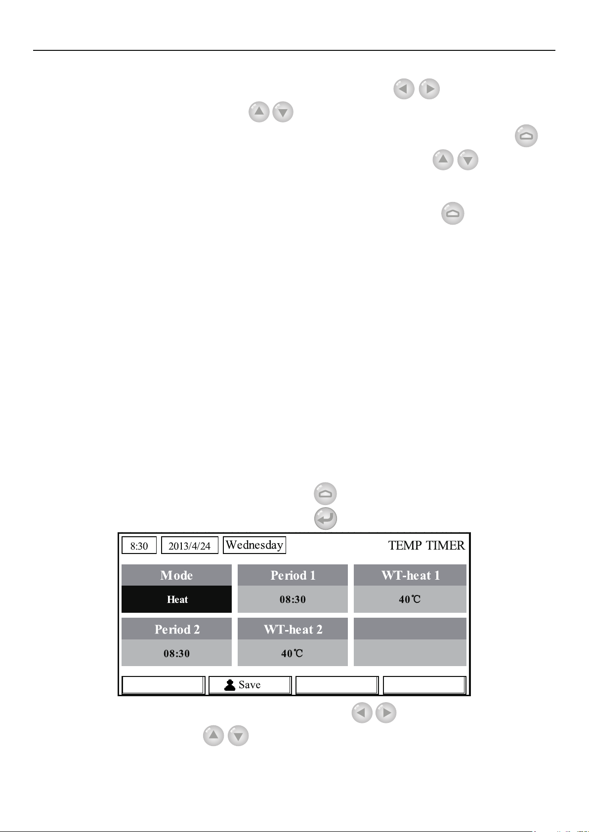
2 At the TEMP TIMER setting page, by the Left/Right key
and then by the Up/Down key
congure it. The congurable parameters include “Mode”,
“Period 1”, “WT-HEAT 1”, “Period 2” and “WT-HEAT 2”.
14
select the desired parameter
Page 19

Operation Instructions
3. When the setting is nished, save it by pressing the Function key no. 2 , or this setting
without being saved is ineffective.
4. When the setting has been saved, activate the “Temp. timer” at the FUNCTION page.
[Notes]
When “Weekly timer”, “Clock timer”, and “Temp. timer” settings are performed at the same
①
time, the last one takes precedence.
This function works only when the unit is in operation.
②
The allowed running modes include “Heat” and “Cool”
③
When the start time of “Period 2” is equal to that of “Period 1”, then the set point of “Period 2”
④
takes precedence.
TEMP. TIMER is judged by the timer value.
⑤
During the setting, the temperature set point which is set manually always takes precedence.
⑥
2.2.15 Solar timer
When the solar system is prepared, this function will decide which period to let the solar system
to run. However, if the solar system will run virtually depends on the temperature difference between
the solar panel and the water tank.
[Operation Instructions]
1. Go to the FUNCTION page and locate “Solar timer”, then press OK key
as shown below
No. Full Name Displayed Name Range Default
1 Solar kit start time Start time 0:00~24:00 8:00
2 Solar kit stop time Stop time 0:00~24:00 18:00
.
to go to the page
2. At the “Solar Timer” page, locate “Start time” or “End time” through the up and down keys
and then adjust the start or stop time also through the up and down keys
.
3. After conguration, press “Save” and then a dialog box will pop up. In the dialog box, press “OK”
to conrm the conguration, or press “Cancel” to cancel this conguration.
4. After saving the conguration, this page will automatically back to the FUNCTION page with
the cursor stayed at “Solar timer”, and then through the up and down keys
to set it to be “ON”
to activate “Solar timer”.
[Notes]
Once “Solar timer” is activated,it cannot be deactivated through ON/OFF operation but be
①
15
Page 20
Operation Instructions
done manually.
“Start time” and “End time” will be memorized upon power failure
②
It can be set under both ON and OFF states
③
2.2.16 Floor Debug
This function will make the unit to perform periodic preheating to the oor for the initial run once
oor coils have been installed.
[Operation Instructions]
1. At the homepage, by pressing the Function key
locate where “Floor debug” is, after that, press OK key
access to the FUNCTION page, and then
to go to the FLOOR DEBUG setting
page.
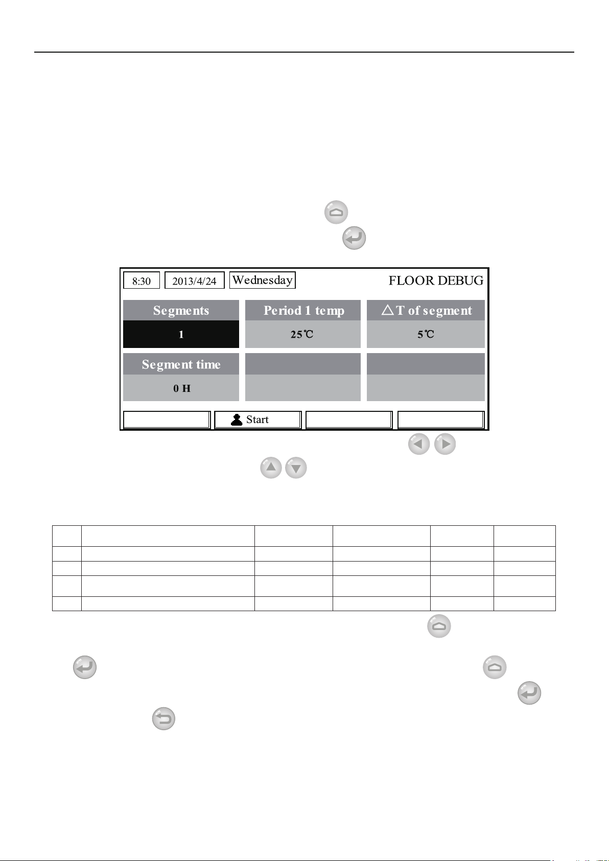
2. At the FLOOR DEBUG setting page, by the Left/Right key
parameter and then by the Up/Down key
congure it. The congurable parameters include
select the desired
“Segments”, “Period 1 temp”, “ΔT of segment”, and “Segment time”, as listed in the following
table.
No. Full Name
1 Segments for oor debug Segments 1~10 1 1
2 First temperature for oor debug Period 1 temp 25~35°C/77~95°F 25°C/77°F 1°C/1°F
Segment temperature difference for
3
4 Segments duration for oor debug Segment time 2~10°C/36~50°F 5°C/41°F 1°C/1°F
oor debug
Displayed
Name
ΔT of segment 0~72H 0 12H
Range Default Accuracy
3. After the above setting is nished, by pressing the function key no.2 activate this function
and a dialog box will pop up, reminding “Start the Floor Debug Mode now?”. If so, press the “OK”
key
box also will pop up, reminding “Stop the Floor Debug Mode now?” If so, press the OK key
not, press “Cancel”
. Once “Floor debug” has been activated, by pressing the function key no.2 , a dialog
; if
to go on.
[Notes]
This function can be activated only when the unit is OFF. When it is intended to activate this
①
function with the unit being ON, a dialog box will pop up, warning “Please turn off the system rst!”.
When this function has been activated, it is unable to turn on or off the unit. In this case,
②
16
Page 21
Operation Instructions
when pressing the ON/OFF key , a dialog will pop up, warning “Please disable the Floor Debug
Mode!”.
When this function has been set successfully, “Timer week”, “Clock timer” and “Temp timer”
③
will be deactivated.
”When “Floor debug” mode has been activated, “Emergen.mode”, “Sanitize”, “Holiday
④
mode” is not allowed to be activated, or a dialog box will pop up, warning “Please disable the Floor
Debug Mode!”.
Upon power failure, this function will be OFF and runtime will be cleared.
⑤
At the FlOOR DEBUG setting page, the control will remain at this page and never back to the
⑥
homepage unless pressing the Return key
When this function is activated, it is allowed to check the target temperature and runtime of
⑦
“Floor Debug” at the Parameter View page.
Before activating “Floor debug”, please make sure each period for “Floor debug” is not
⑧
zero, or a dialog box will pop up, warning “Wrong Floor Debug time!”. It will resume only by pressing
“OK” and then correcting the time.
or Menu key .
2.2.17 Emergency Mode (Emergen. Mode)
When the compressor fails to run owing to some urgent condition, this function will allow the unit
to run in the “Heat” or “Hot water” mode through the auxiliary heater and the water tank heater.
[Operation Instructions]
1. Set “Mode” to “Heat” or “Hot water” at the Parameter Set page
2. Then, switch pages to go the page where “Emergen. mode”, locate it by the Left/Right key
, and congure it to “On” or “Off” by the Up/Down key
3. When it is set to “On”, “Auxiliary func.” at the homepage will be replaced by “Emergen.
Mode”.
4. When it is set to “On” but the running mode is not “Heat” or “Hot water”, a dialog will pop up,
warning “Wrong running mode!”. In this case, by pressing the OK key , the control will go to
.
the Mode setting page, or by pressing the Cancel key
Mode” page.
[Notes]
When the unit is performing “Heat” at the Emergency mode, if there is water flow switch
①
protection, IDU assistant heater welding protection, or leaving water temperature sensor error, the
Emergency mode will quit and will not be allowed to be activated.
When the unit is performing “Hot water” at the Emergency mode, if there is water tank heater
②
welding protection, or water tank temperature sensor error, the Emergency mode will quit and will not
be allowed to be activated.
At the Emergency mode, the ON/OFF key
③
mode will not be allowed to be changed; the Quiet Mode and Weather-dependent Mode cannot be
deactivated; “Weekly timer”, “Clock timer” and “Temp timer” also cannot be activated, or will be
deactivated if being activated.
At the Emergency mode, commands from the Thermostat is ineffective.
④
At the Emergency mode, only one running mode between “Heat” and “Hot water” is allowed.
⑤
This function can be activated only when the unit is OFF, or a dialog box will pop up, warning
⑥
, the control will return to the “Emergen.
operation will be disabled; the running
17
Page 22

Operation Instructions
“Please turn off the system rst!”
Under the Emergency mode, “Floor debug”, “Sanitize”, “Holiday mode”, cannot be
⑦
activated, or a dialog box will pop up, warning “ Please disable the Emergency Mode!”.
Upon power failure, the “Emergen. mode” will be defaulted to be “Off”.
⑧
2.2.18 Holiday Mode
In winter or low-temperature season, this function will control the leaving water temperature or
room temperature within a certain range to avoid the water system from being frozen when the user
is out on holiday for a long time.
[Operation Instructions]
1. Locate where “Holiday mode” at the Parameter Set page
2. Set Holiday to “On” or “Off” by the Up/Down key
[Notes]
At the holiday mode, “Mode” setting of the control and On/Off key operation both are
①
disabled.
When it is activated, “Weekly timer”, “Clock timer” or “Temp timer” will be deactivated.
②
At the holiday mode, when “T-Room” is adopted, the temperature set point should be 15
③
when “T-Out water” is adopted, then the temperature set point should be 30
It will quit when the thermostat effectively works (“Cool” or “OFF” operation).
④
When this setting is saved successfully, it will be memorized upon power failure.
⑤
This function can be activated only at the “Heat” mode and with the unit turned off. When it is
⑥
done with the unit turned on, a prompt dialog box will pop up, warning “Please turn off the system
first!”; or when it is done at other modes except the “Heat” Mode with the unit turned off, also a
prompt dialog box will pop up, warning “Wrong running mode!”.
When it is activated, the ON/OFF key
⑦
warning “Please disable the Holiday Mode !”.
Under the Holiday mode, “Floor debug”, “Sanitize”, “Emergen. mode” cannot be activated,
⑧
or a dialog box will pop up, warning “Please disable the Holiday Mode !”.
operation is disabled, or a dialog box will pop up,
.
.
2.2.19 Thermostat
;
When the thermostat has been installed, it can be used to control the run mode of the unit (only
“Heat”or “Cool”mode)
[Operation Instructions]
1. Locate where “Thermostat” is at the FUNCTION page
2. By pressing the Up/Down key
the control follows the running mode of the thermostat and is not allowed to set the running mode;
when it is “Off”, the control follows the running mode set by itself.
[Notes]
When “Floor debug” or “Emergen. Mode” is activated, then the control will not receive
①
signals from the thermostat.
If “Thermostat” is set to “On”, the control will automatically disable some functions concerning
②
timer, and run in accordance with the mode set by the thermostat. In this case, the running mode is
unchangeable and the ON/OFF key
When this setting is saved successfully, it will be memorized upon power failure.
③
The state of the Thermostat can be changed when the unit is turned off.
④
, Thermostat can be set to “On” or “Off”. When it is “On”,
operation of the control is ineffective.
18
Page 23

Operation Instructions
2.2.20 Assistant Heater(Assis. Heater)
There are three options for the assistant heater, “ 1 group”, “2 groups” or “Without”.
[Operation Instructions]
Go to the FUNCTION page and locate “Assistant heater”, then, configure it through the Up/
Down key
[Notes]
●It will be memorized upon power failure.
, “With” or “Without”.
2.2.21 Other Heater
It can be congured to “With” or “Without” through the wired controller.
[Operation Instructions]
Go to the FUNCTION page and locate Other heater, then, congure it through the Up/Down key
, “With” or “Without”.
[Notes]
●It will be memorized upon power failure.
2.2.22 Chassis Heater
The user will decide if to activate or deactivate the chassis heater. Generally it is suggested
to activate it under low environment temperature, “Heat” mode or “Hot water” mode to prevent the
chassis from being frozen.
[Operation Instructions]
Go to the FUNCTION page and locate “Chassis Heater” then, congure it through the Up/Down
key
, “On” or “Off”.
[Notes]
●It will be memorized upon power failure.
2.2.23 Tank heater
When the water tank is installed, it is suggested to activate it. In this case, the water tank will
go to the standby status and will start after the control program has made this decision based on the
actual demand and the environment temperature.
[Operation Instructions]
Go to the FUNCTION page and locate “Tank heater” then, congure it through the Up/Down key
, “On” or “Off”.
[Notes]
●It will be memorized upon power failure.
2.2.24 Plate heater
The plate heater can be activated or deactivated by the user. Generally it is suggested to activate
it when the water pump has stopped and the environment temperature is lower than 2°C so as to
prevent the heat exchanger from being frozen.
[Operation Instructions]
Go to the FUNCTION page and locate “Plate heater” then, congure it through the Up/Down key
, “On” or “Off”.
19
Page 24

Operation Instructions
[Notes]
●It will be memorized upon power failure.
2.2.25 Solar antifre
When the solar system has been installed, it is highly suggested to activate this function.
[Operation Instructions]
Go to the FUNCTION page and locate “Solar antifre” then, congure it through the Up/Down
key
[Notes]
, “On” or “Off”.
●It will be memorized upon power failure.
2.2.26 Water Tank
It can be congured to be “With” or “Without” based on the actual condition.
[Operation Instructions]
Go to the FUNCTION page and locate “Water tank” then, congure it through the Up/Down key
, “With” or “Without”.
[Notes]
It will be memorized upon power failure.
①
This setting is allowed only when the unit is turned off.
②
2.2.27 Tank Sensor
When the water tank has been installed, one group or two groups of tank sensors can be
selected to detect and control the water tank temperature.
[Operation Instructions]
Go to the FUNCTION page and locate “Water tank”, then, congure it through the Up/Down key
, “1” or “2”. When the water tank is unavailable, this option will be reserved.
[Notes]
●It will be memorized upon power failure.
2.2.28 Solar Heater
It can be congured to be “With” or “Without” based on the actual condition.
[Operation Instructions]
Go to the FUNCTION page and locate “Solar heater”, then, congure it through the Up/Down
key
[Notes]
, “With” or “Without”.
●It will be memorized upon power failure.
2.2.29 Floor cong
It can be congured to be “With” or “Without” based on the actual condition.
[Operation Instructions]
Go to the FUNCTION page and locate “Floor cong”, then, congure it through the Up/Down
key
[Notes]
, “With” or “Without”.
20
Page 25

Operation Instructions
It will be memorized upon power failure.
①
When it is set to be “with”, the water temperature is not allowed to be set to “High temp.”
②
2.2.30 Radia cong
It can be congured to be “With” or “Without” based on the actual condition.
[Operation Instructions]
Go to the FUNCTION page and locate “Radia cong”, then, congure it through the Up/Down
key
[Notes]
, “With” or “Without”.
It will be memorized upon power failure.
①
When it is set to “with”, the water temperature is defaulted to be “High temp.”
②
2.2.31 FCU
It can be congured to be “With” or “Without” based on the actual condition.
[Operation Instructions]
Go to the FUNCTION page and locate “FCU”, then, congure it through the Up/Down key
, “With” or “Without”.
[Notes]
●It will be memorized upon power failure.
2.2.32 Remote Sensor
It can be congured to be “With” or “Without” based on the actual condition.
[Operation Instructions]
Go to the FUNCTION page and locate “Remote sensor”, then, congure it through the Up/Down
key
, “With” or “Without”.
[Notes]
It will be memorized upon power failure.
①
“T-room ctrl” can be selected only when the Remote Sensor is set to “With”.
②
2.2.33 Air removal
This function is intended to expel air inside the water system with only the water pump in
operation when installation of the unit is nished.
[Operation Instructions]
Go to the FUNCTION page and locate “Air removal”, then, congure it through the Up/Down
key
[Notes]
, “On” or “Off”.
It will not be memorized upon power failure.
①
It can be set only when the unit is turned off.
②
2.2.34 Address
It is used to identify the unit in use in the central control system.
[Operation Instructions]
Go to the FUNCTION page and locate “Address”, then, congure it through the Up/Down key
21
Page 26
Operation Instructions
to set the address.
[Notes]
It indicates the address of the control and is intended for the group control.
①
It will not be memorized upon power failure.
②
The address range is [0,125] and [127,253]
③
The default address is 1 for the initial use.
④
2.2.35 Gate-Controller
It can be congured to be “On” or “Off” based on the actual condition.
[Operation Instructions]
Go to the FUNCTION page and locate “Gate-Controller”, then, configure it through the Up/
Down key
[Notes]
When it is activated, the control will check the card is inserted or not. If inserted, the control
①
will run normally; if not, the control will turn off the unit and back to the homepage. In this case, any
key operation is ineffective (except for the combined key operation), or a dialogue box will pop up,
warning"Keycard uninserted!".
It will not be memorized upon power failure.
②
, “On” or “Off”.
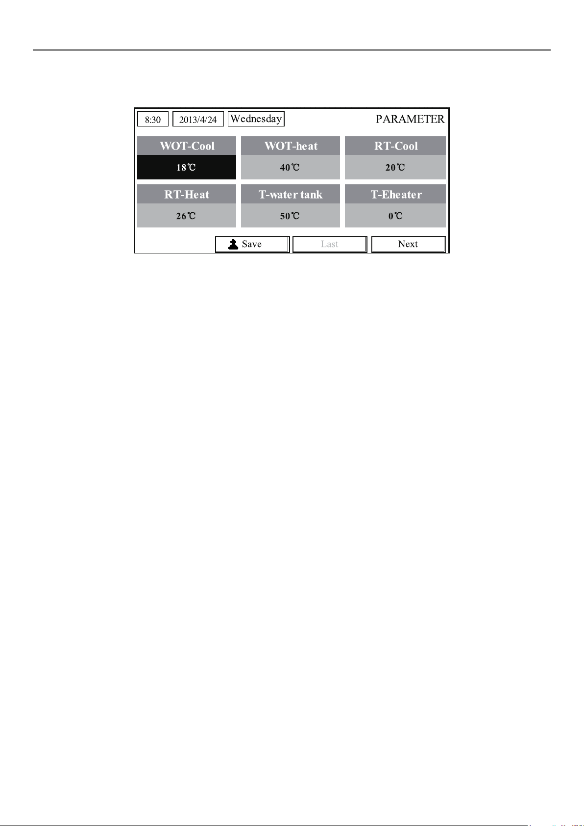
2.3 Parameter Setting (Parameter Set)
2.3.1 User Parameter Setting
At the parameter setting pages, each parameter is congurable, like: water out temperature for
cooling, water out temperature for heating, and water tank temperature etc.
[Operation Instructions]
1. At the homepage, it is able to go to the PARAMETER page by pressing the Function key no.2
.
2. At the Parameter Set page, by the Left/Right key
then by the Up/Down key
changed when pressing and holding the key.
3. When the setting is nished, press “Save”
settings?”. If so, press the OK key ; if not press the Cancel key to not save this setting.
[Notes]
increase or decrease the setting value which will be continuously
and a dialog box will pop up, reminding “Save
select the desired option and
22
Page 27
Operation Instructions
For those parameter which default value vary by different condition, the value will set to
①
default when the condition changes.
User Setting
23
Page 28

Operation Instructions
No. Full Name
Water out temperature
1
for cooling
Water out temperature
2
for heating
Room temperature for
3
cooling
Room temperature for
4
heating
5 Tank temperature T-water tank 40~80°C 104~176°F 50°C/122°F
Eheater-on ambient
6
temperature
Extra-heater-on
7
ambient temperature
Max heat pump
8
waterout temperature
(no eheater)
Solar kit-max water
9
temp
Lower limit ambient
temperature at the
10
Weather-dependent
Mode for heating
Upper limit
temperature at the
11
Weather-dependent
Mode for heating
Upper limit room
temperature at the
12
Weather-dependent
Mode for heating
Displayed
Name
WOT-Cool
WOT-Heat
RT-Cool 18~30°C 64~86°F 24°C/75°F
RT-Heat 18~30°C 64~86°F 20°C/68°F
T-Eheater -22~18°C -8~64°F -7°C/19°F
T-Extraheater -22~18°C -8~64°F -15°C/5°F
T-HP Max 40~50°C 104~122°F 50°C/122°F
Solarwater Max 50~80°C 122~176°F 80°C/176°F
Lower AT-Heat -22~5°C -8~41°F -20°C/-4°F
Upper AT-Heat 10~37°C 50~99°F 25°C/77°F
Upper RT-Heat 22~30°C 72~86°F
Range(°C) Range(°F) Default
7~25°C
[With FCU]
18~25°C
[Without FCU]
25~61°C[High temp.]
25~55°C[Normal temp.]
45~77°F
[With FCU]
64~77°F
[Without FCU]
77~142°F[High temp.]
77~131°F[Normal temp.]
7°C/45°F[With FCU]
18°C/64°F[Without FCU]
45°C/113°F[High temp.]
35°C/95°F[Normal.]
24°C/75°F
Set to default value when
the Weather-dependent
Mode setting changes.
Lower limit room
temperature at the
13
Weather-dependent
Mode for heating
Upper limit water-out
temperature at the
14
Weather-dependent
Mode for heating
Lower limit water-out
temperature at the
15
Weather-dependent
Mode for heating
Lower limit ambient
temperature at the
16
Weather-dependent
Mode for cooling
Upper limit
temperature at the
17
Weather-dependent
Mode for cooling
Upper limit room
temperature at the
18
Weather-dependent
Mode for cooling
Lower limit room
temperature at the
19
Weather-dependent
Mode for cooling
Upper limit water-out
temperature at the
20
Weather-dependent
Mode for cooling
18°C/68°F
Lower RT-Heat 18~21°C 64~70°F
Upper WT-Heat
Lower WT-Heat
Lower AT-Cool 8~25°C 46~77°F 25°C/77°F
Upper AT-Cool 26~50°C 79~122°F 40°C/104°F
Upper RT-Cool 24~30°C 75~86°F 27°C/81°F
Lower RT-Cool 18~23°C 64~73°F 22°C/72°F
Upper WT-Cool
56~61°C[High temp.]
30~55°C[Normal temp.]
55~58°C[High temp.]
25~29°C[Normal temp.]
15~25°C[With FCU]
22~25°C[Without FCU]
133~142°F[High temp.]
86~95°F
[Normal temp.]
131~136°F[High temp.]
77~84°F
[Normal temp.]
59~77°F
[With FCU]
72~77°F
[Without FCU]
Set to default value when
the Weather-dependent
Mode setting changes.
61°C/142°F[High temp.]
35°C/95°F[Low temp.]
Set to default value when
the Weather-dependent
Mode setting changes.
50°C/131°F[High temp.]
29°C/84°F[Low temp.]
Set to default value when
the Weather-dependent
Mode setting changes.
15°C/59°F[With FCU]
23°C/73°F[Without FCU]
24
Page 29
Operation Instructions
Lower limit water-out
temperature at the
21
weather-dependent
mode for cooling
Temperature deviation
22
for cooling
Temperature deviation
23
for heating
Temperature deviation
24
for heating water
25 Room temp variation ΔT-Room temp 1~5°C 36~41°F 2°C/36°F
Lower WT-Cool
ΔT-Cool 2~10°C 36~50°F 5°C/41°F
ΔT-Heat 2~10°C 36~50°F 10°C/50°F
ΔT-hot water 2~8°C 36~46°F 5°C/41°F
7~14°C[With FCU]
18~21°C[Without FCU]
45~57°F[With FCU]
64~70°F[Without FCU]
7°C/45°F[With FCU]
18°C/64°F[Without FCU]
26 Run time Run time 1~10min
Solar kit-start temp
27
variation
Solar battery-max.
28
temp
T-Solar start 10~30°C 50~86°F 15°C/59°F
SL- battery Max 90~130°C 194~266°F 110°C/230°F
/ 3min[with FCU]
/ 5min[witnout FCU]
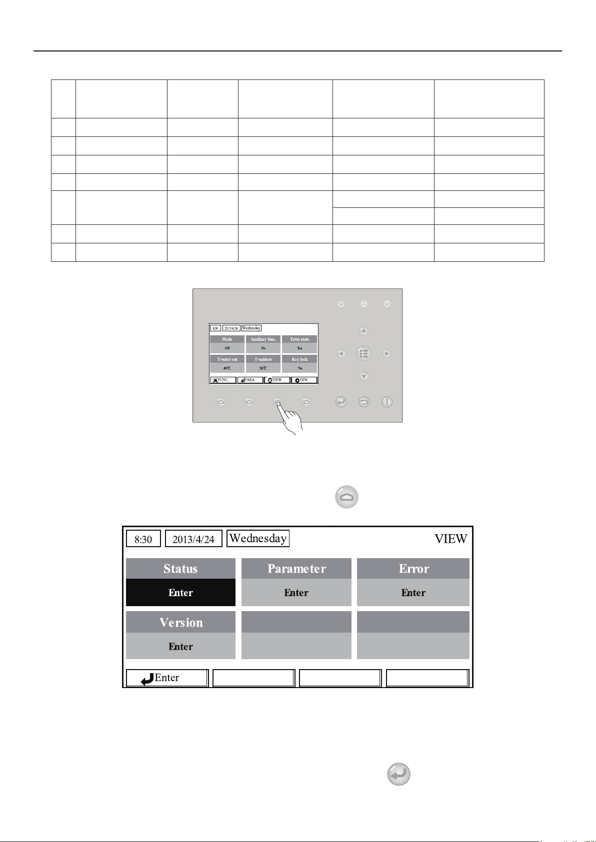
2.4 View
At the view pages, the user is enabled to view the unit’s running state, running parameters,
errors, version of the wired controller etc.
[Operation Instructions]
At the homepage, by pressing the Function key no.3
, it is able to go to the VIEW page as
shown in the gure below.
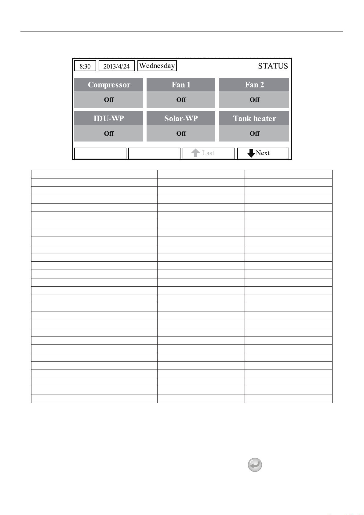
2.4.1 Status View
At the status view pages, the user is enabled to view the unit’s running status, like compressor
On/Off, fan 1 On/Off, water pump On/Off, antifreeze On/Off, defrost On/Off etc.
[Operation Instructions]
1. At the VIEW page, select “Status” and then press the OK key
to go to the STATUS page.
25
Page 30
Operation Instructions
2. At the STATUS page, it is able to check the status of each component.
Viewable Components
Full Name Displayed Name Status
Compressor running state Compressor On/Off
Fan 1 running state Fan 1 On/Off
Fan 2 running state Fan 2 On/Off
Heat pump-water pump HP-pump On/Off
Solar water pump running state SL-pump On/Off
Swimming pool-water pump Swimming-pump On/Off
Tank heater running state Tank heater On/Off
3-Way valve 1 running state 3-way valve 1 On/Off
3-Way valve 2 running state 3-way valve 2 On/Off
Crankcase heater running state Crankc.heater On/Off
Chassis heater running state Chassis heater On/Off
Plate heat exchanger heater Plate heater On/Off
Defrost Defrost On/Off
Oil return Oil return On/Off
Thermostat Thermostat Off/Cool/Heat
Assistant heater running state Assist. Heater On/Off
Circulating two-way valve 1 running state 2-way valve 1 On/Off
Circulating two-way valve 2 running state 2-way valve 2 On/Off
Doorguard Doorguard Card in/Card out
Opration LED Opration LED On/Off
Error LED Error LED On/Off
4-way valve running state 4-way valve On/Off
Enthalpy-enhancing solenoid valve En.valve On/Off
Heat pump-auxiliary heater 1 HP-heater 1 On/Off
Heat pump-auxiliary heater 2 HP-heater 2 On/Off
Solar kit- freeze protection SL-Antifree Enabled/Disabled
Heat pump-freeze protection HP-Antifree Enabled/Disabled
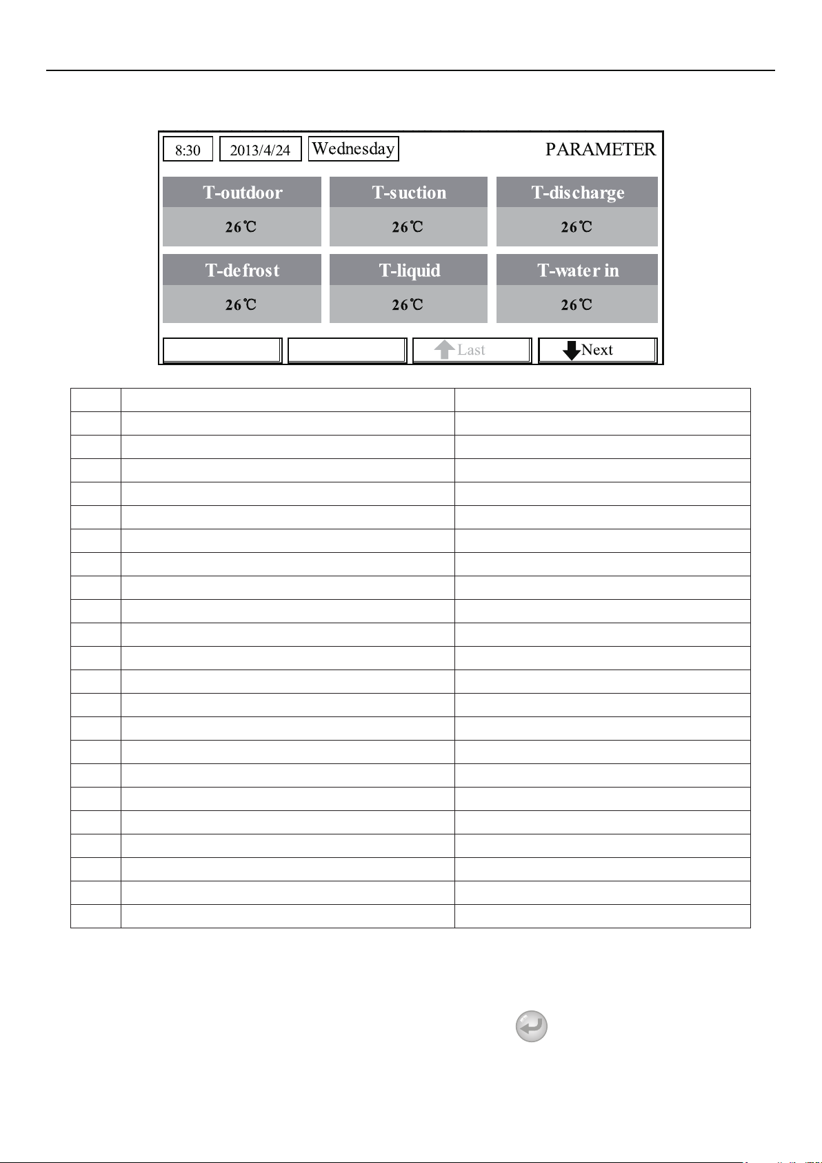
2.4.2 Parameter View (Para View)
At the parameter view pages, the unit is enabled to view the units’ running parameters, like
outdoor temperature, suction temperature, discharge temperature, water in temperature, water out
temperature etc.
[Operation Instructions]
1. At the VIEW page, select Parameter and then press the OK key
page.
26
to go to the Para View
Page 31
Operation Instructions
2. At the Para View page, it is able to view each parameter.
No. Full Name Displayed Name
1 Outdoor temperature T-outdoor
2 Suction temperature T-suction
3 Discharge temperature T-discharge
4 Defrost temperature T-defrost
5 Plate heat exchanger Water in temperature T-water in PE
6 Plate heat exchanger water-out temperature T-waterout PE
7 E-heater water-out temperature T-waterout EH
8 Water tank temperature set point T-tank ctrl.
9 Water tank temperature reading T-tank display
10 Remote room temperature T-remote room
11 Solor kit-entering water temp T-SL water I
12 Solor kit-leaving water temp T-SL water O
13 Solar battery temp T-SL battery
14 Swimming pool-water temp T-Swimming
15 Swimming pool-entering water temp T-Swimming in
16 Swimming pool-leaving water temp T-Swimming out
17 Discharge pressure Dis.pressure
18 Enthalpy-enhancing pressure En.pressure
19 Suction pressure Su.pressure
20 Target temperature for Weather-dependent Mode T-auto mode
21 Target temperature for oor debug T-oor debug
22 Time period for oor debug Debug time
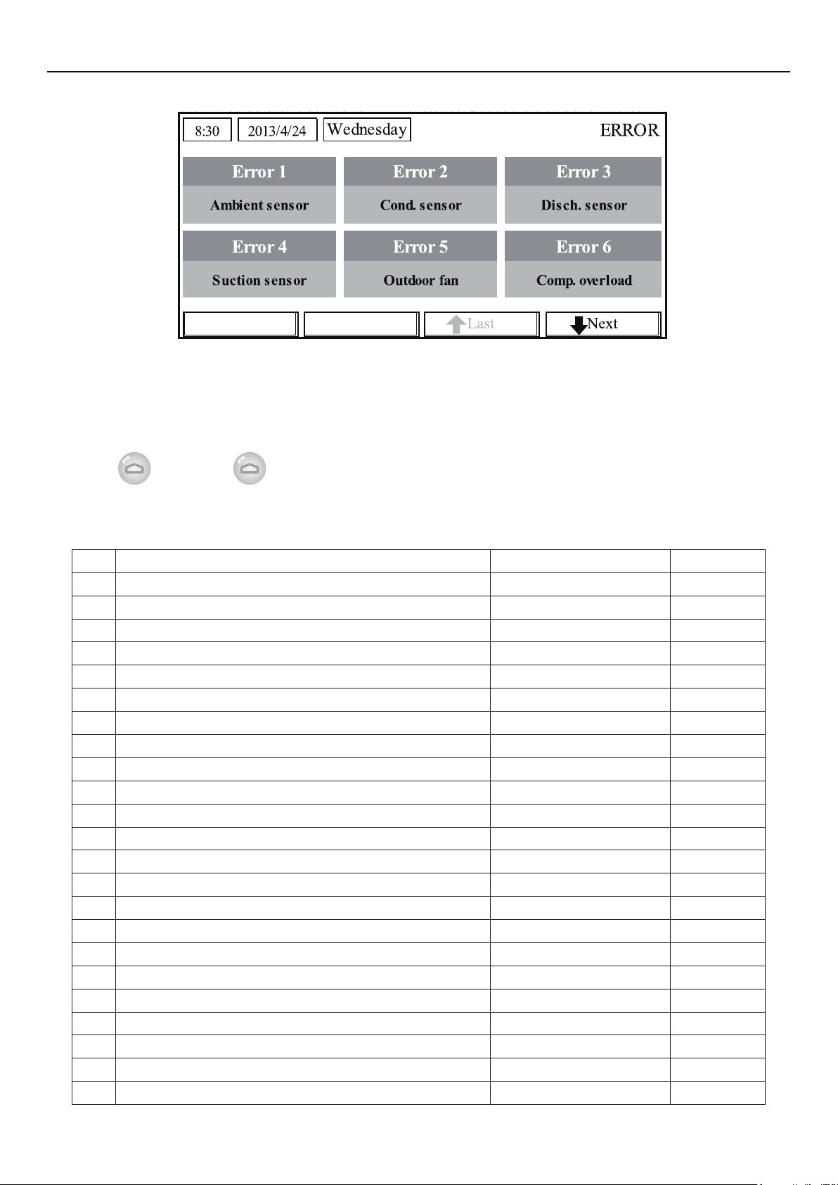
2.4.3 Error View
At the error view pages, the user is enabled to see which error the unit suffers.
[Operation Instructions]
1. At the VIEW page, select Error and then press the OK key
2. At the Error View page, it is able to view each error.
27
to go to the ERROR page.
Page 32
Operation Instructions
[Notes]
The real-time error will show on the control. Taking Error 2 in the above gure for example,
①
when it is recovered, it will disappear and be replaced by Error 3, and other errors follow the same
way.
If the total no. of errors exceed six, other errors should be viewed by switching pages through
②
“Last”
③
and “Next” .
Any one among “IDU auxiliary heater 1 error”, “IDU auxiliary heater 2 error”, “Water tank
heater error” occurs, the control will beep until this error has been cleared.
● See the following table for error description.
No. Full Name Displayed Name Error Code
1 Ambient temperature sensor error Ambient sensor F4
2 Defrost temperature sensor error Defro. sensor d6
3 Discharge temperature sensor error Disch. sensor F7
4 Suction temperature sensor error Suction sensor F5
5 Outdoor fan error Outdoor fan EF
6 Compressor internal overload protection Comp. overload H3
7 High pressure protection High pressure E1
8 Low pressure protection Low pressure E3
9 High discharge protection Hi-discharge E4
10 Refrigerant loss protection Refri-loss P2
11 Heat pump-water pump protection HP-pump E0
12 Solar kit-water pump protection SL-pump EL
13 Swimming pool-water pump protection Swimming-pump
14 Incorrect capacity DIP switch setting Capacity DIP c5
15 Communication error between indoor and outdoor unit ODU-IDU Com. E6
16 Drive communication error Drive com. -----
17 High pressure sensor error HI-pre. sens. FC
18 Enthalpy-enhancing sensor error En. senser F8
19 Low pressure sensor error LOW-pre. Sens. dl
20 Heat exchanger-leaving water temperature sensor error Temp-HELW F9
21 Auxiliary heater-leaving water temperature sensor error Temp-AHLW dH
22 Refrigerant liquid line temperature sensor error Temp-RLL F1
23 Heat exchanger-entering water temperature sensor error Temp-HEEW
28
Page 33

Operation Instructions
24 Water tank water temperature sensor 1 error Tank sens. 1 FE
25 Water tank water temperature sensor 2 error Tank sens. 2
26 Solar kit-entering water temp sensor T-SL water out
27 Solar kit-leaving water temp sensor T-SL water in FH
28 Solar kit- temp sensor T-solar battery FF
29 Swimming pool-entering water temp sensor T-Swimming in
30 Swimming pool-leaving water temp sensor T-Swimming out
31 Swimming pool-water temp sensor T-Swimming
32 Remote room sensor 1 T-Remote Air1 F3
33 Remote room sensor 2 T-Remote Air2
34 Heat pump-water ow switch HP-Water SW EC
35 Solar kit-water ow switch SL-Water SW F2
36 Swimming pool-water ow switch SW-Water SW F1
37 Welding protection of the auxiliary heater 1 Auxi. heater 1 EH
38 Welding protection of the auxiliary heater 2 Auxi. heater 2 EH
39 Welding protection of the water tank heater Auxi. -WTH EH
40 Under-voltage DC bus or voltage drop error DC under-vol. PL
41 Over-voltage DC bus DC over-vol. PH
42 AC current protection (input side) AC curr. pro. PA
43 IPM defective IPM defective H5
44 PFC defective FPC defective HC
45 Start failure Start failure LC
46 Phase loss Phase loss LD
47 Drive module resetting Driver reset P6
48 Compressor over-current Com. over-cur. P0
49 Overspeed Overspeed P5
50 Sensing circuit error or current sensor error Current sen. LF
51 Desynchronizing Desynchronize PC
52 Compressor stalling Comp. stalling H7
53 Communication error drive-main com. LE
54 Radiator or IPM or PFC module overtemperature Overtemp.-mod. P8
55 Radiator or IPM or PFC module temperature sensor error T-mod. sensor P7
56 Charging circuit error Charge circuit Pu
57 Incorrect AC voltage input AC voltage PP
58 Drive board temperature sensor error Temp-driver PF
59 AC contactor protection or input zero crossing error AC contactor P9
60 Temperature drift protection Temp. drift PE
Current sensor connection protection (current sensor not
61
connected to phase U/V)
62 Communication error to the outdoor unit ODU Com. E6
63 Communication error to the indoor unit IDU Com. E6
64 Communication error to the drive Driver Com. E6
65 Solar kit-superheating Solarsuperheat F6
Sensor con. PD
29
Page 34
Operation Instructions
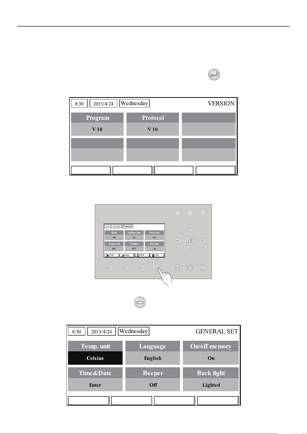
2.4.4 Version View (VERSION)
At the version view page, the user is enabled to see the version of the program and the protocol.
[Operation Instructions]
1. At the VIEW page, select Version and then press the OK key to go to the VERSION
page.
2. At the VERSION page, the program and protocol versions are listed.
2.5 General Setting
At the general setting pages, the user is enabled to configure general parameters, like
temperature unit, language, On/off memory, time & date etc.
[Operation Instructions]
At the homepage, by pressing “GEN.”
able to set “Temp. unit”, “Language”, “On/off memory”, “Time & Date”, “Beeper” and “Back light”,
as shown in the gure below.
access to the GENERAL SET page. At this page, it is
30
Page 35
Operation Instructions
No. Full Name Displayed Name Range Default Remarks
1 Temperature unit Temp. unit Celsius/Fahrenheit Celsius /
2 Language Language
3 On/off memory On/off memory On/Off On /
4 Time&Date Time&Date / / /
5 Beeper Beeper On/Off On /
6 Back light Back light
/English English /
中文
Lighted/Energy
save
Energy save
“On”: it always lights
on.
“Eco”: it lights off
when there is no
key operation for 1
minute, and will lights
on where there is any
key operation.
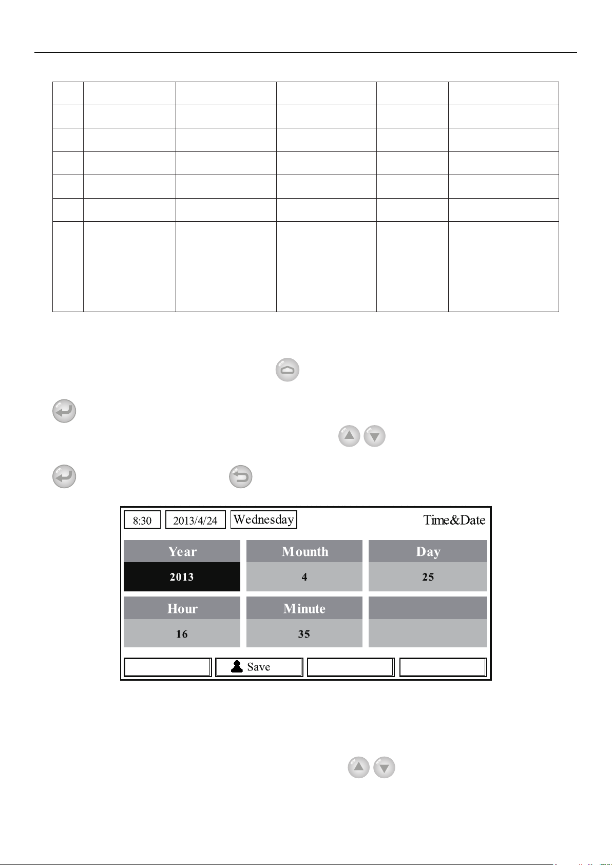
2.5.1 Time&Date
[Operation Instructions]
At the homepage, by pressing “GEN.”
“Time & Date” at this page. After that, go to the “Time & Date” setting page by pressing the OK key
.
Change the set value by pressing the Up/Down key
access to the GENERAL SET page. Then, select
. Then by pressing “Save”, a pop-
up window will pop up to remind if you are determined to save this setting. If so, press the OK key
. If not, press the Cancel key to not save this setting. The saving setting will update at the
upper left corner of the control.
2.6 Key Lock
This function can be activated or deactivated through the wired controller. Once it is activated,
any key operation will become ineffective.
[Operation Instructions]
At the homepage, by pressing the up and down keys
simultaneously for 5 seconds, it
is able to activate or deactivate this function. When it is activated, any key operation is ineffective and
the key lock icon in main page and standby page will display Yes.
31
Page 36
Operation Instructions
32
Page 37

Page 38

NOTE CONCERNING PROTECTION OF
ENVIRONMENT
This product must not be disposed of via normal household waste after its service life, but must be
taken to a collection station for the recycling of electrical and electronic devices. The symbol on the
product, the operating instructions or the packaging indicate such disposal procedures. The materials
are recyclable in accordance with their respective symbols. By means of re-use, material recycling or
any other form of recycling old appliances you are making an important contribution to the protection
of our environment. Please ask your local council where your nearest disposal station is located.
PRODUCER
SINCLAIR CORPORATION Ltd.
1-4 Argyll St.
London W1F 7LD
Great Britain
www.sinclair-world.com
This product was manufactured in China (Made in China).
REPRESENTATIVE, TECHNICAL SUPPORT
NEPA spol. s r.o.
Purkyňova 45
612 00 Brno
Czech republic
Tel.: +420 541 590 140
Fax: +420 541 590 124
www.sinclair-solutions.com
info@sinclair-solutions.com
 Loading...