

SINAMICS G120 User Manual
Siemens D 11.1 · 2009
4
4/2 SINAMICS G120 standard inverters
4/2 Overview
4/4 Benefits
4/4 Applications
4/4 Design
4/9 Configuration
4/10 Technical specifications
4/12 CU230 Control Units
4/12 Overview
4/12 Selection and ordering data
4/12 Function
4/13 Design
4/14 Integration
4/17 Technical specifications
4/19 CU240 Control Units
4/19 Overview
4/19 Selection and ordering data
4/20 Design
4/22 Integration
4/28 Technical specifications
4/30 PM240 Power Modules
0.37 kW to 250 kW (0.5 hp to 400 hp)
4/30 Overview
4/31 Selection and ordering data
4/32 Integration
4/36 Technical specifications
4/42 Characteristic curves
4/44 Dimensional drawings
4/50 PM250 Power Modules
7.5 kW to 75 kW (10 hp to 100 hp)
4/50 Overview
4/51 Selection and ordering data
4/52 Integration
4/55 Technical specifications
4/59 Characteristic curves
4/60 Dimensional drawings
4/64 PM260 Power Modules
11 kW to 55 kW (15 hp to 75 hp)
4/64 Overview
4/65 Selection and ordering data
4/66 Integration
4/68 Technical specifications
4/71 Characteristic curves
4/72 Dimensional drawings
4/73 Compact inverters
0.37 kW to 15 kW (0.5 hp to 20 hp)
4/73 Overview
4/73 Selection and ordering data
4/74 Line-side power components
4/74 Line filters
4/77 Line reactors
4/81 Recommended line components
4/83 DC link components
4/83 Braking resistors
4/86 Braking Modules
4/88 Load-side power components
4/88 Output reactors
4/95 Sine-wave filters
4/102 Supplementary system components
4/102 Intelligent Operator Panel IOP
4/104 Basic Operator Panel BOP
4/105 MMC memory card
4/106 CM240NE chemical industry module
4/108 PC Connection Kit -2
4/108 PC Connection Kit
4/109 Brake relay
4/110 Safe Brake Relay
4/111 Adapter for mounting on DIN rails
4/111 Shield Connection Kit
4/112 Shield Connection Kit 1
for CU230P-2 Control Units
4/112 Shield Connection Kit
for CU240S Control Units
4/113 Spare parts
4/113 CU240 Spare Parts Kit
4/113 Replacement door
for PM240 frame size FSGX
4/114 Terminal Cover Kit
for frame sizes FSD and FSE
4/114 Terminal Cover Kit
for frame size FSF
4/115 Replacement connector
4/116 Replacement fan
SINAMICS G120
Standard inverters
0.37 kW to 250 kW (0.5 hp to 400 hp)
© Siemens AG 2009
SINAMICS G120
Standard inverters 0.37 kW to 250 kW (0.5 hp to 400 hp)
SINAMICS G120 standard inverters
4/2
Siemens D 11.1 · 2009
4
■
Overview
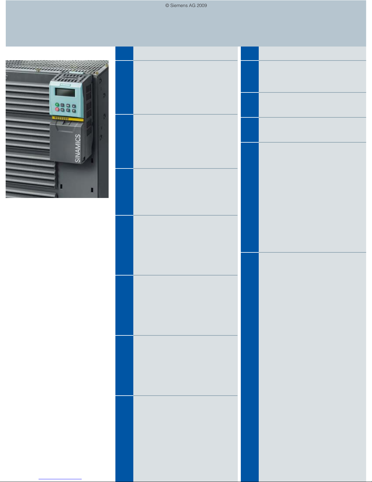
The SINAMICS G120 frequency inverter is designed to provide
precise and cost-effective speed/torque control of AC motors.
With different device versions (frame sizes FSA to FSGX) in a
power range from 0.37 kW to 250 kW (0.5 hp to 400 hp), it is suitable for a wide variety of drive solutions.
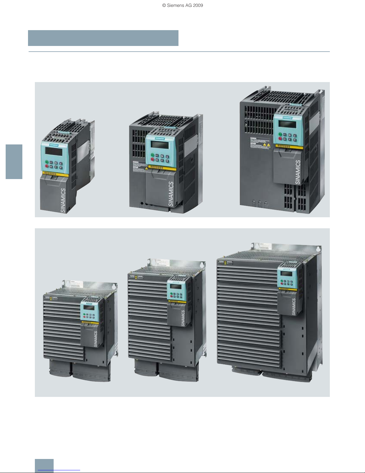
Examples of SINAMICS G120, frame sizes FSA, FSB and FSC; each with Power Module, Control Unit and Basic Operator Panel
Examples of SINAMICS G120, frame sizes FSD, FSE and FSF; each with Power Module, Control Unit and Basic Operator Panel
© Siemens AG 2009

SINAMICS G120
Standard inverters 0.37 kW to 250 kW (0.5 hp to 400 hp)
SINAMICS G120 standard inverters
4/3
Siemens D 11.1 · 2009
4
■
Overview
Examples of SINAMICS G120, frame size FSGX;
with Power Module
Modularity
SINAMICS G120 is a modular inverter system comprising a
variety of functional units. The main units are:
• the Control Unit (CU)
• the Power Module (PM)
The Control Unit
controls and monitors the Power Module and
the connected motor using several different control types that
can be selected. It supports communication with a local or
central control and monitoring devices.
The Power Module
supplies the motor in a power range 0.37 kW
to 250 kW (0.5 hp to 400 hp). The Power Module is controlled by
a microprocessor in the Control Unit. State-of-the-art IGBT technology with pulse-width modulation is used to achieve the highest degree of reliability and flexible motor operation. Comprehensive protection functions provide a high degree of protection
for the Power Module and the motor.
Furthermore, a large number of additional components
are avail-
able, such as:
• Intelligent Operator Panel (IOP) for parameterizing, diagno-
sing, controlling and copying drive parameters
• Basic Operator Panel (BOP) for parameterizing, diagnosing,
controlling and copying drive parameters
• Line filters, Classes A and B
• Line reactors
• Braking resistors
• Sine-wave filters
• Output reactors
Safety Integrated
The SINAMICS G120 standard inverters are available in a number of different versions for safety-related applications. All Power
Modules are already designed for Safety Integrated. A Safety
Integrated Drive can be created by combining a Power Module
with the appropriate Fail-safe Control Unit.
The SINAMICS G120 fail-safe frequency inverter provides four
safety functions, certified in accordance with EN 954-1,
Category 3 and IEC 61508 SIL 2:
• Safe Torque Off (STO) to protect against active movement of
the drive
• Safe Stop 1 (SS1) for continuous monitoring of a safe braking
ramp
• Safely Limited Speed (SLS) for protection against dangerous
movements when a speed limit is exceeded
• Safe Brake Control (SBC) for controlling motor brakes that are
active in the de-energized state, e.g. motor holding brakes
The functions “Safe Stop 1” and “Safely Limited Speed” can
both be implemented without having to use a motor sensor or
encoder; the implementation cost is minimal. Existing systems in
particular can be updated with safety technology without the
need to change the motor or mechanical system.
The safety functions “Safely Limited Speed” and “Safe Stop 1”
are not certified for pull-through loads as in the case of lifting
gear and winders.
Additional information is provided in the part Highlights, section
Safety Integrated.
Efficient Infeed Technology
The innovative Efficient Infeed Technology is used in PM250 and
PM260 Power Modules. This technology allows the energy produced by motors operating in generator mode connected to
standard inverters to be fed back into the supply system. Additional cooling and additional space requirement in the control
cabinet can be avoided as components such as braking resistors, brake choppers and line reactors are not required. Further,
wiring and engineering costs are significantly reduced. At the
same time, considerable savings can be achieved in terms of
energy consumption and operating costs.
Additional information is included in the part Highlights, section
Efficient Infeed Technology.
Innovative cooling concept and coated electronic modules
The innovative cooling concept and coated electronic modules
significantly increase the service life and usage time of the device. These features are based on the following principles:
• The power loss is exclusively dissipated using an external
heat sink
• Electronic modules not located in air duct
• Standardized convection cooling of Control Unit
• All cooling air from the fan is directed through the heat sink
STARTER commissioning tool
The STARTER commissioning tool simplifies the commissioning
and maintenance of SINAMICS G120 inverters. The operator
guidance combined with comprehensive, user-friendly functions
for the relevant drive solution allow you to commission the device
quickly and easily.
© Siemens AG 2009

SINAMICS G120
Standard inverters 0.37 kW to 250 kW (0.5 hp to 400 hp)
SINAMICS G120 standard inverters
4/4
Siemens D 11.1 · 2009
4
■
Benefits
7 Modularity ensures flexibility for a drive concept that is fit-for-
the-future
- Modules can be replaced under voltage (hot swapping)
- Pluggable terminals
- The modules can be easily replaced, which makes the
system extremely service friendly.
7 The safety functions make it easier to integrate drives into
safety-oriented machines or plants
7 Communications-capable via PROFINET or PROFIBUS with
PROFIdrive Profile 4.0
- Reduced number of interfaces
- Plantwide engineering
- Easy to handle
7 The innovative circuit design (bidirectional input rectifier with
“pared-down” DC link) allows the kinetic energy of a load to be
fed back into the supply system when Power Modules PM250
and PM260 are used. This feedback capability provides enormous potential for savings because generated energy no
longer has to be converted into heat in a braking resistor
7 Innovative SiC semiconductor technology ensures that when
a PM260 Power Module is used, the inverter is more compact
than a comparable standard converter with an optional sinewave filter for the same power rating
7 An innovative cooling concept and coated electronic modules
increase robustness and service life
- External heatsink
- Electronic components are not located in air duct
- Control Unit that is completely cooled by convection
- Additional coating of the most important components
7 Simple unit replacement and quick copying of parameters
using the optional Basic Operator Panel or the optional MMC
memory card
7 Quiet motor operation as a result of the high pulse frequency
7 Compact, space-saving design
7 Software parameters for simple adaptation to 50 Hz or 60 Hz
motors (IEC or NEMA motors)
7 2-/3-wire control (static/pulsed signals) for universal control
via digital inputs (only CU240 Control Units)
7 Engineering and commissioning with uniform engineering
tools such as SIZER, STARTER, and Drive ES: ensure fast engineering and easy commissioning – STARTER is integrated in
STEP 7 with Drive ES Basic with all the advantages of central
data storage and totally integrated communication
7 Certified worldwide for compliance with CE, UL, cUL, c-tick
and Safety Integrated according to IEC 61508 SIL 2
■
Applications
SINAMICS G120 is ideally suited
• as a universal drive in all industrial and commercial applications
• e.g. in the automotive, textile, printing and chemical industries
• for higher-level applications, e.g. in conveyor systems
■
Design
SINAMICS G120 standard inverters are modular frequency inverters for standard drives. Each SINAMICS G120 comprises
two operative units – the Power Module and Control Unit. Each
Control Unit can be combined with each Power Module.
Guidelines for module selection
The procedure to select a complete SINAMICS G120 frequency
inverter should be as follows:
Control Units
The Control Unit performs closed-loop control functions for the
inverter. In addition to the closed-loop control, it has additional
functions that can be adapted to the particular application
through parameterization.
Two series of Control Units are available for SINAMICS G120
corresponding to their software packages (CU230 and CU240).
Each Control Unit comprises a defined I/O quantity structure, a
special fieldbus interface and possible additional safety functions. The following Control Units and accessories are available
for standard SINAMICS G120 inverters:
CU230 Control Units
The CU230P-2 Control Units have been specifically designed for
pump, fan and compressor applications. The following three versions are available:
• CU230P-2 HVAC
• CU230P-2 DP
• CU230P-2 CAN
CU240 Control Units
Several Control Units are available in different versions:
• CU240E
• CU240S
• CU240S DP
• CU240S DP-F
• CU240S PN
• CU240S PN-F
1. Select a suitable Control Unit (depending on the required communication, hardware and software version and safety functionality)
2. Select a suitable Power Module (depending on the power and
technology required)
3. Select the optional and additional components. There are a large
number of components for expanding the system (e.g. line-side
power components, DC link components, load-side power components, and supplementary system components). However, it
should be noted that not all of the components are required for all
of the Power Modules (example: Braking resistors are not required
for the PM250 and PM260 Power Modules!). The precise data is
provided in the technical specifications tables of the particular
components.
© Siemens AG 2009

SINAMICS G120
Standard inverters 0.37 kW to 250 kW (0.5 hp to 400 hp)
SINAMICS G120 standard inverters
4/5
Siemens D 11.1 · 2009
4
■
Design
Power Modules
The following Power Modules are available for the
SINAMICS G120 standard inverters:
PM240 Power Modules
PM240 Power Modules (0.37 kW to 250 kW / 0.5 hp to 400 hp)
feature an integrated brake chopper (for frame size FSGX external) and are designed for drives without energy recovery capability. Generator energy produced during braking is converted to
heat via externally connected braking resistors.
PM250 Power Modules
PM250 Power Modules (7.5 kW to 90 kW / 10 hp to 125 hp) have
an innovative circuit design which allows line-commutated energy recovery back into the line supply. This innovative circuit
permits generator energy to be fed back into the supply system
and therefore saves energy.
PM260 Power Modules
PM260 Power Modules (11 kW to 55 kW / 15 hp to 75 hp) also
have an innovative circuit design which allows line-commutated
energy recovery back into the line supply. This innovative circuit
permits generator energy to be fed back into the supply system
and therefore saves energy. The PM260 Power Modules also have
an integrated sine-wave filter that limits the rate of rise of voltage
and the capacitive charging/discharging currents usually associated with inverter operation.
Line-side power components
The following line-side power components are available for
SINAMICS G120 standard inverters:
Line filters
With one of the additional line filters, the Power Module reaches
a higher radio interference class.
Line reactors (for PM240 Power Modules only)
A line reactor reduces the system perturbations caused by
harmonics. This particularly applies in the case of weak line
supplies (line supply short-circuit power u
K
>1%).
Recommended line components
This is a recommendation for additional line-side components,
such as fuses and circuit-breakers (line-side components must
be dimensioned in accordance with IEC standards). Additional
information about the listed fuses and circuit breakers can be
found in Catalogs LV 1 and LV 1 T.
DC link components
The following DC link components are available for the
SINAMICS G120 standard inverters:
Braking Modules (only for PM240 Power Modules, frame
size FSGX)
A Braking Module and the matching external braking resistor are
required to bring drives with a PM240 Power Module, frame
size FSGX to a controlled standstill in the event of a power failure
(e.g. emergency retraction or EMERGENCY STOP Category 1)
or limit the DC link voltage during a short period of generator
operation. The Braking Module includes the power electronics
and the associated control circuit.
Braking resistors (for PM240 Power Modules only)
Excess energy in the DC link is dissipated in the braking resistor.
The braking resistors are designed for use with PM240 Power
Modules. They are equipped with an integrated brake chopper
(electronic switch). There is an optional plug-in Braking Module
for frame size FSGX.
Load-side power components
The following load-side power components are available for the
SINAMICS G120 standard inverters. This means that during operation with output reactors or sine-wave filters, longer, shielded
motor cables are possible and the motor service life can be extended:
Output reactors (for PM240 and PM250 Power Modules only)
Output reactors reduce the voltage stress on the motor wind-
ings. At the same time, the capacitive charging/discharging currents, which place an additional load on the power unit when
long motor cables are used, are reduced.
Sine-wave filter (not for PM260 Power Modules)
The sine-wave filter limits the rate of rise of voltage and the
capacitive charging/discharging currents that usually occur with
inverter operation. An output reactor is not required.
© Siemens AG 2009

SINAMICS G120
Standard inverters 0.37 kW to 250 kW (0.5 hp to 400 hp)
SINAMICS G120 standard inverters
4/6
Siemens D 11.1 · 2009
4
■
Design
Power and DC link components which are optionally available depending on the Power Module used
The following line-side power components, DC link components
and load-side power components are optionally available in the
appropriate frames sizes for the Power Modules:
U = Base component
S = Lateral mounting
I = Integrated
– = Not possible
F = Power Modules available with and without integrated class A filter
Frame size
FSA FSB FSC FSD FSE FSF FSGX
PM240 Power Module with integrated brake chopper without inte-
grated brake
chopper
Available frame sizes ✓ ✓ ✓ ✓ ✓ ✓ ✓
Line-side power components
Line filter, class A U F F F F F/S
3)
S
3)
Line filter, class B U U U – – – –
Line reactor U U U U U S S
DC link components
Braking resistor U U S S S S S
Braking Module – – – – – – I (Option)
Load-side power components
Output reactor U U U S S S S
Sine-wave filter U U U S S S S
PM250 Power Module with line-commutated energy recovery
Available frame sizes – – ✓ ✓ ✓ ✓ –
Line-side power components
Line filter, class A – – I F F F –
Line filter, class B – – U – – – –
Line reactor
1)
– – –
1)
–
1)
–
1)
–
1)
–
DC link components
Braking resistor
2)
– – –
2)
–
2)
–
2)
–
2)
–
Load-side power components
Output reactor – – U S S S –
Sine-wave filter – – U S S S –
PM260 Power Module with line-commutated energy recovery and integrated sine-wave filter
Available frame sizes – – – ✓ – ✓ –
Line-side power components
Line filter, class A – – – F – F –
Line filter, class B – – – – – – –
Line reactor
1)
– – – –
1)
– –
1)
–
DC link components
Braking resistor
2)
– – – –
2)
– –
2)
–
Load-side power components
Output reactor – – – – – – –
Sine-wave filter – – – I – I –
1)
A line reactor is not required and must not be used in conjunction with a
PM250 or PM260 Power Module.
2)
Line-commutated energy recovery is possible in conjunction with a PM250
or PM260 Power Module. A braking resistor cannot be connected and is
not necessary.
3)
PM240 FSF Power Modules, from 110 kW (150 hp) and higher and FSGX
are only available without an integrated class A filter. An optional class A
line filter for side mounting is available instead.
© Siemens AG 2009

SINAMICS G120
Standard inverters 0.37 kW to 250 kW (0.5 hp to 400 hp)
SINAMICS G120 standard inverters
4/7
Siemens D 11.1 · 2009
4
■
Design
General design information
Frequency inverters comprising a Power Module (PM) and a Control Unit
(CU) and two base components at position 1 and position 2 (side view)
• A maximum of two base components plus inverter are possible.
• The line filter has to be mounted directly below the frequency
inverter (position 1).
• With lateral mounting, the line-side components have to be
mounted on the left side of the frequency inverter and the
load-side components on the right side.
• Braking resistors have to be mounted directly on the control
cabinet wall due to heating issues.
Recommended installation combinations of the inverter and optional power and DC link components
Inverter chassis unit
SINAMICS G120 e. g.
Filter
Base components
e. g.
Reactor
Mounting
surface or
cabinet wall
Position1Position
2
G_D011_EN_00187
CU PM
Power
Modules
Base Lateral mounting
Frame size Position 1 Position 2 left of the inverter
(for line-side power
components)
right of the inverter
(for load-side power
components and
DC link components)
FSA and FSB Line filter Line reactor – Output reactor or
sine-wave filter and/or
braking resistor
Line filter or
line reactor
Output reactor or
sine-wave filter
– Braking resistor
Line filter or
line reactor
Braking resistor – –
Line filter or
line reactor or
braking resistor
– – –
FSC
Line filter Line reactor – Output reactor or
sine-wave filter and/or
braking resistor
Line filter or
line reactor
Output reactor or
sine-wave filter
– Braking resistor
FSD and FSE Line reactor – Line filter Output reactor or
sine-wave filter and/or
braking resistor
FSF – – Line filter and/or
line reactor
Output reactor or
sine-wave filter and/or
braking resistor
FSGX – – Line filter and/or
line reactor
Output reactor or
sine-wave filter and/or
braking resistor
© Siemens AG 2009

SINAMICS G120
Standard inverters 0.37 kW to 250 kW (0.5 hp to 400 hp)
SINAMICS G120 standard inverters
4/8
Siemens D 11.1 · 2009
4
■
Design
Maximum permissible cable lengths from the motor to the
inverter when using output reactors or sine-wave filters
depending on the voltage range and the Power Module being
used
The following load-side power components in the appropriate
frame sizes are optionally available for the Power Modules and
result in the following maximum cable lengths:
Maximum permissible motor cable lengths (shielded/unshielded) in m
Frame sizes
FSA FSB FSC FSD FSE FSF FSGX
PM240 Power Module with integrated brake chopper without inte-
grated brake
chopper
Available frame sizes ✓ ✓ ✓ ✓ ✓ ✓ ✓
Without output reactor/sine-wave filter
50/100 50/100 50/100 50/100 100/100 150/150 300/450
With optional output reactor
• at 380 V (– 10 %) to 400 V 3 AC 150/225 150/225 150/225 200/300 200/300 200/300 300/450
• at 401 V to 480 V (+ 10 %) 3 AC 100/150 100/150 100/150 200/300 200/300 200/300 300/450
With optional sine-wave filter
• at 380 V (– 10 %) to 400 V 3 AC 200/300 200/300 200/300 200/300 200/300 200/300 300/450
• at 401 V to 480 V (+ 10 %) 3 AC 200/300 200/300 200/300 200/300 200/300 200/300 300/450
PM250 Power Module with line-commutated energy recovery
Available frame sizes – – ✓ ✓ ✓ ✓ –
Without output reactor/sine-wave filter – – 50/100 50/100 50/100 50/100 –
With optional output reactor
• at 380 V (– 10 %) to 400 V 3 AC – – 150/225 200/300 200/300 200/300 –
• at 401 V to 480 V (+ 10 %) 3 AC – – 100/150 200/300 200/300 200/300 –
With optional sine-wave filter
• at 380 V (– 10 %) to 400 V 3 AC – – 200/300 200/300 200/300 200/300 –
• at 401 V to 480 V (+ 10 %) 3 AC – – 200/300 200/300 200/300 200/300 –
PM260 Power Module with line-commutated energy recovery and integrated sine-wave filter
Available frame sizes – – – ✓ – ✓ –
With integrated sine-wave filter
• at 500 V to 690 V 3 AC (± 10 %) – – – 200/300 – 200/300 –
© Siemens AG 2009

SINAMICS G120
Standard inverters 0.37 kW to 250 kW (0.5 hp to 400 hp)
SINAMICS G120 standard inverters
4/9
Siemens D 11.1 · 2009
4
■
Design
Supplementary system components
The following supplementary system components are available
for the SINAMICS G120 standard inverters:
Intelligent Operator Panel IOP
The IOP supports both entry-level personnel and drive experts.
Thanks to the large plain text display, the menu prompting and
the Application Wizards, it is easy to commission, diagnose and
locally control standard drives.
Operator Panel BOP (not for CU230P-2 Control Units)
The Basic Operator Panel BOP can be plugged onto the Control
Unit and can be used to commission drives, monitor drives in
operation and input individual parameter settings. The BOP also
provides a function to quickly copy parameters.
MMC memory card (not for CU240E Control Units)
The parameter settings for an inverter can be stored on the MMC
memory card. When service is required, e.g. after the inverter
has been replaced and the data have been downloaded from
the memory card the drive system is immediately ready for use
again. The associated slot is located on the top of the Control
Unit.
CM240NE chemical industry module
Inverters for 400 V / 500 V and 690 V are required in the chemical
industry that meet the special demands and requirements of this
industry sector. The essential requirements and demands of the
chemical industry are fulfilled using the SINAMICS G120 series
of inverters supplemented by the CM240NE chemical industry
module (with ATEX-certified PTC evaluation and a NAMUR terminal strip).
PC Inverter Connection Kit
For controlling and commissioning an inverter directly from a PC
if the appropriate software (STARTER commissioning tool) has
been installed.
The STARTER commissioning tool on DVD is included in the PC
Inverter Connection Kit.
Brake Relay
The Brake Relay allows the Power Module to be connected to an
electromechanical motor brake, thereby allowing the motor
brake to be driven directly by the Control Unit.
Safe Brake Relay
The Safe Brake Relay allows the Power Module to be connected
to an electromechanical motor brake, allowing the brake to be
directly and safely controlled from the Control Unit in accordance with EN 954-1 Category 3 and IEC 61508 SIL 2.
Adapter for mounting on DIN rails
The adapter for mounting on DIN rails can be used to mount in-
verters of the sizes FSA and FSB on DIN mounting rails (2 units
with a center-to-center distance of 100 mm).
Shield Connection Kit
The Shield Connection Kit makes it easier to connect the shields
of supply and control cables, offers mechanical strain relief and
thus ensures optimum EMC performance.
Shield Connection Kit for CU240S and CU230P-2
The Shield Connection Kit offers optimum shield connection and
strain relief for all signal and communication cables. It includes
a matching shield bonding plate and all of the necessary connecting and retaining elements for mounting.
Spare parts
Spare Parts Kit for CU240
The kit includes a replacement cover for the terminals, a suitable
shield bar for the CU240E Control Unit including screws, replacement connector for the CU240S Control Unit, protective
element of the MMC card slot and screws to attach the shield
bonding plate of the CU240S Control Unit.
Term ina l Cov er K it
The kit includes a replacement cover for the terminals. The kit can
be ordered for PM240 Power Modules, frame sizes FSD, FSE and
FSF, as well as for the PM260, frame size FSF.
PM260 replacement connector
This spare part includes a connector for the input and output sides
for the PM260 Power Module, frame size FSD.
SINAMICS G120 PM240 FSGX replacement door
A complete replacement door can be ordered for the PM240
Power Module, frame size FSGX.
Replacement fan
The Power Module fans are designed for extra long service life.
Replacement fans can be ordered for special applications.
■
Configuration
The following electronic configuring and engineering tools are
available for the SINAMICS G120 standard inverters:
Selection guide, SD Configurator
More than 100000 products with approximately 5 million possible product versions from the area of drive technology are listed
in the interactive Catalog CA 01 – the Offline Mall from Siemens
IA&DT. In order to make it easier to select the optimum motor
and/or inverter from the wide range of Standard Drives, the SD
Configurator was developed, which is integrated as “Selection
guide” in this catalog on the DVD together with the selection and
engineering tools.
Online SD Configurator
In addition, the SD Configurator can be used in the Internet with-
out requiring any installation. The SD Configurator can be found
in the Siemens Mall under the following address:
http://www.siemens.com/dt-configurator
SIZER configuration tool
The SIZER PC tool makes it easy to configure the SINAMICS and
MICROMASTER 4 drive family. It provides support when selecting the hardware and firmware components necessary to implement a drive task. SIZER supports the configuration of the complete drive system, from simple single-motor drives up to
complex multi-axis applications.
STARTER commissioning tool
The STARTER commissioning tool is used to commission, optimize and diagnose drives in a menu-prompted fashion. In
addition to SINAMICS drives, STARTER is also suitable for
MICROMASTER 4 units and the frequency converters for the
distributed I/O SIMATIC ET 200S FC and
SIMATIC ET 200pro FC.
Drive ES engineering system
Drive ES is the engineering system used to integrate the communication, configuration and data management functions of
Siemens drive technology into the SIMATIC automation world
easily, efficiently and cost-effectively. The STEP 7 Manager user
interface forms the basis. Various software packages are available for SINAMICS:
Drive ES Basic, Drive ES SIMATIC and Drive ES PCS 7.
© Siemens AG 2009

SINAMICS G120
Standard inverters 0.37 kW to 250 kW (0.5 hp to 400 hp)
SINAMICS G120 standard inverters
4/10
Siemens D 11.1 · 2009
4
■
Technical specifications
Unless explicitly specified otherwise, the following technical
specifications are valid for all the following components of the
SINAMICS G120 standard inverters.
Mechanical specifications
Vibratory load
•Transport 1) acc. to EN 60721-3-2
- All units and components
except frame size FSGX
- Units with frame size FSGX
Class 2M3
Class 2M2
• Operation
Test values acc. to EN 60068-2-6 Test Fc:
10 … 58 Hz: Constant deflection
0.075 mm
58 … 150 Hz: Constant acceleration = 9.81 m/s2 (1 × g)
Shock load
•Transport 1) acc. to EN 60721-3-2
- All units and components
except frame size FSGX
- Units with frame size FSGX
Class 2M3
Class 2M2
• Operation
Test values acc. to
EN 60068-2-27
- Frame sizes FSA to FSC
- Frame sizes FSD to FSF
- Frame size FSGX
Test E a :
147 m/s2 (15 × g)/11 ms
49 m/s2 (5 × g)/30 ms
98 m/s2 (10 × g)/20 ms
Ambient conditions
Protection class
acc. to EN 61800-5-1
Class I (with protective conductor
system) and Class III (PELV)
Touch protection
acc. to EN 61800-5-1
For the intended purpose
Permissible ambient and coolant
temperature (air) during operation for line-side power components and Power Modules
• High overload
(HO)
0…50°C (32…122°F) without
derating
(for PM240, frame size FSGX:
0 … 40 °C),
> 50 … 60 °C see derating
characteristics
• Light overload
(LO)
0…40°C (32…104°F) without
derating
(for PM240, frame size FSGX:
0 … 40 °C),
> 40 … 60 °C see derating
characteristics
Permissible ambient and coolant
temperature (air) during operation for Control Units, additional
system components and DC-link
components
–10…+50°C (14…122°F)
with CU240S DP-F: 0 … 45 °C
with CU240S PN-F: 0 … 40 °C
with IOP: 0 … 50 °C
up to 2000 m above sea level
Climatic ambient conditions
•Storage1) acc. to EN 60721-3-1 Class 1K3
temperature –25 … +55 °C
•Transport1) acc. to EN 60721-3-2 Class 2K4
temperature –40 … +70 °C
max. humidity 95 % at 40 °C
• Operation acc. to EN 60721-3-3 Class 3K5 4)
Condensation, splashwater and
ice formation not permitted
(EN 60204, Part 1)
Ambient conditions (continued)
Environmental class/harmful
chemical substances
•Storage1) acc. to EN 60721-3-1 Class 1C2
•Transport1) acc. to EN 60721-3-2 Class 2C2
• Operation acc. to EN 60721-3-3 Class 3C2
Organic/biological influences
•Storage1) acc. to EN 60721-3-1 Class 1B1
•Transport1) acc. to EN 60721-3-2 Class 2B1
• Operation acc. to EN 60721-3-3 Class 3B1
Degree of pollution
acc. to EN 61800-5-1
2
Certification for fail-safe versions
Applies to CU240 DP-F and
CU240 PN-F Control Units.
The values include Control Unit,
Power Module and Safe Brake
Relay.
• Category acc. to EN 954-1 3
• SIL Cl acc. to IEC 61508 2
• PL acc. to ISO 13849 Available soon
•PFH
D
5 × 10
–8
•T1 10 Years
Standards
Standards conformance UL, cUL, CE, c-tick
CE mark According to Low-Voltage Direc-
tive 73/23/EEC and Machinery
Directive 98/37/EC
EMC Directive acc. to EN 61800-3
• Frame sizes FSA to FSGX without
integrated line filter class A
Category C3
2)
• Frame sizes FSB to FSF with
integrated line filter class A
Category C2 3)
(corresponds to class A acc. to
EN 55011 for conducted interference emission)
• Frame size FSA without integrated line filter and with additional
line filter class A
Category C2 3)
(corresponds to class A acc. to
EN 55011 for conducted interference emission)
• Frame size FSA with additional
line filter class A and with additional line filter class B
Category C2 3)
(corresponds to class B acc. to
EN 55011 for conducted interference emission)
• Frame sizes FSB and FSC with
additional line filter class A and
with additional line filter class B
Category C2 3)
(corresponds to class B acc. to
EN 55011 for conducted interference emission)
Note: The EMC product standard EN 61800-3 does not apply directly
to a frequency inverter but to a PDS (Power Drive System), which comprises the complete circuitry, motor and cables in addition to the frequency inverters. The frequency inverters on their own do not generally
require identification according to the EMC Directive.
1)
In transport packaging.
2)
Unfiltered inverters can be used in industrial environments as long as they
are part of a system that contains line filters on the higher-level infeed side.
As a consequence, a PDS (Power Drive System) can be installed according to C3.
3)
With shielded motor cable up to 25 m.
4)
For Intelligent Operator Panel IOP, class 3K3.
© Siemens AG 2009

SINAMICS G120
Standard inverters 0.37 kW to 250 kW (0.5 hp to 400 hp)
SINAMICS G120 standard inverters
4/11
Siemens D 11.1 · 2009
4
■
Technical specifications
Compliance with standards
CE mark
The SINAMICS G120 inverters meet the requirements of the
Low-Voltage Directive 73/23/EEC.
Low-Voltage Directive
The inverters comply with the following standards listed in the
official journal of the EU:
• EN 60204
Safety of Machinery, electrical equipment of machines
• EN 61800-5-1
Electrical power drive systems with variable speed – Part 5-1:
Requirements regarding safety – electrical, thermal, and energy requirements
UL listing
Inverter devices in UL category NMMS certified to UL and cUL,
in compliance with UL508C. UL list numbers E121068 and
E192450.
For use in environments with pollution degree 2.
Also see the Internet under http://www.ul.com
Machinery Directive
The inverters are suitable for installation in machines. Compliance with the Machinery Directive 98/37/EC requires a separate
certificate of conformity. This must be provided by the plant construction company or the organization marketing the machine.
EMC Directive
• EN 61800-3
Variable-speed electric drives
Part 3: EMC product standard including specific test methods
The EMC product standard EN 61800-3 has been valid for electric drive systems since 07/01/2005. The transition period for the
predecessor standard EN 61800-3/A11 from February 2001
ended on October 1, 2007. The following information applies to
SINAMICS G120 frequency inverters from Siemens:
• The EMC product standard EN 61800-3 does not apply
directly to a frequency inverter but to a PDS (Power Drive
System), which comprises the complete circuitry, motor and
cables in addition to the inverter.
• Frequency inverters are normally only supplied to experts for
installation in machines or systems. A frequency inverter must,
therefore, only be considered as a component which, on its
own, is not subject to the EMC product standard EN 61800-3.
The inverter's operating manual, however, specifies the conditions regarding compliance with the product standard if the
frequency inverter is expanded to become a PDS. For a PDS,
the EMC Directive in the EU is complied with by observing the
product standard EN 61800-3 for variable-speed electric
drive systems. The frequency inverters on their own do not
generally require identification according to the EMC Directive.
• In the Standard EN 61800-3 from July 2005, a distinction is no
longer made between “general availability” and “restricted
availability”. Instead, different categories C1 to C4 have been
defined in accordance with the environment of the PDS at the
operating location:
- Category C1: Drive systems for rated voltages < 1000 V for
use in the first environment
- Category C2: Stationary drive systems not connected by
means of a plug connector for rated voltages < 1000 V.
When used in the first environment, the system must be installed and commissioned by personnel familiar with EMC
requirements. A warning note is required.
- Category C3: Drive systems for rated voltages < 1000 V for
exclusive use in the second environment. A warning note is
required.
- Category C4: Drive systems for rated voltages ≥ 1000 V or
for rated currents ≥ 400 A or for use in complex systems in
the second environment. An EMC plan must be generated.
• The EMC product standard EN 61800-3 also defines limit values for conducted interference and radiated interference for
the so-called “second environment” (= industrial power supply systems that do not supply households). These limit values
are below the limit values of filter class A to EN 55011. Unfiltered inverters can be used in industrial environments as long
as they are part of a system that contains line filters on the
higher-level infeed side.
• With SINAMICS G120, Power Drive Systems (PDS) that fulfill
the EMC product standard EN 61800-3 can be configured
when observing the installation instructions in the product
documentation.
• A differentiation must be made between the product standards for electrical drive systems (PDS) of the range of standards EN 61800 (of which Part 3 covers EMC topics) and the
product standards for the devices/systems/machines, etc.
This will probably not result in any changes in the practical use
of frequency inverters. Since frequency inverters are always
part of a PDS and these are part of a machine, the machine
manufacturer must observe various standards depending on
their type and environment (e.g. EN 61000-3-2 for line harmonics and EN 55011 for radio interference). The product
standard for PDS on its own is, therefore, either insufficient or
irrelevant.
• With respect to the compliance with limits for line supply harmonics, the EMC product standard EN 61800-3 for PDS refers
to compliance with the EN 61000-3-2 and EN 61000-3-12
standards.
• Regardless of the configuration with SINAMICS G120 and its
components, the machine construction company (OEM) can
also apply other measures to ensure that the machine complies with the EU EMC Directive. The EU EMC Directive is generally fulfilled when the relevant EMC product standards are
observed. If they are not available, the generic standards (e.g.
DIN EN 61000-x-x) can be used instead. It is important that
the conducted and emitted interference at the line connection
point and outside the machine remain below the relevant limit
values. Any suitable technical measures can be applied to ensure this.
SEMI F47
SEMI F47 is an industry standard relating to the immunity to voltage dips. This includes the requirement that industrial equipment must be able to tolerate defined dips or drops of the line
supply voltage. As a result, industrial equipment that fulfills this
standard is more reliable and productive. In the SINAMICS G120
product family, the PM240 and PM250 Power Modules fulfill the
latest SEMI F47-0706 standard. In the case of a voltage dip, defined in accordance with SEMI F47-0706, these drives either
continue to supply a defined output current, or using an automatic restart function, continue to operate as expected.
© Siemens AG 2009

SINAMICS G120
Standard inverters 0.37 kW to 250 kW (0.5 hp to 400 hp)
CU230 Control Units
4/12
Siemens D 11.1 · 2009
4
■
Overview
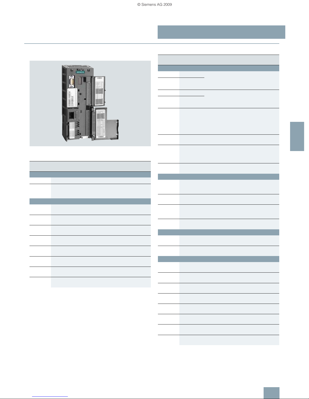
Example: CU230P-2 HVAC Control Unit with Intelligent Operator Panel
IOP on the PM240 Power Module, frame size FSC
The CU230P-2 Control Units are especially suitable for drives
with integrated technological functions for pump, fan and compressor applications. The I/O interface, the fieldbus interfaces
and the additional software functions optimally support these
applications. The integration of technological functions is a significant differentiating feature to the other Control Units of the
SINAMICS G120 drive family.
■
Selection and ordering data
■
Function
Closed-loop control
• Linear and square torque characteristics for fluid flow and
positive displacement machines
• ECO mode for additional energy saving
• Vector control without encoder for sophisticated control tasks
Connections
• Two analog inputs (current/voltage can be selected) to directly
connect pressure/level sensors
• Two additional analog inputs to connect NI1000/PT1000 temperature sensors
• Direct control of valves and flaps using two 230 V relays
Interfaces
• PROFIBUS, USS, CANopen and Modbus RTU communication
Software functions
• Automatic restart function after power failure
• Flying restart
• Kinetic buffering (V
dc min
control)
• PID controller for temperature, pressure, air quality, level
• Energy saving using the “hibernation mode”
• Load check function to monitor belts and flow
• Real time clock with three time generators
IOP wizards for special applications such as e.g.
• Pumps: Positive displacement (constant load torque) and
centrifugal pumps (square load torque) with and without
PID controller
• Fans: Radial and axial fans (square load torque) with and without PID controller
• Compressors: Positive displacement (constant load torque)
and fluid flow machines (square load torque) with and without
PID controller
Communication Digital inputs Digital outputs Analog inputs Analog outputs Designation Control Unit
Order No.
Standard
RS485/USS;
Modbus RTU
6342CU230P-2HVAC6SL3243-0BA30-1HA0
PROFIBUS DP 6 3 4 2 CU230P-2 DP 6SL3243-0BA30-1PA0
CANopen 6 3 4 2 CU230P-2 CAN 6SL3243-0BA30-1CA0
new
new
new
© Siemens AG 2009
SINAMICS G120
Standard inverters 0.37 kW to 250 kW (0.5 hp to 400 hp)
CU230 Control Units
4/13
Siemens D 11.1 · 2009
4
■
Design
CU230P-2 HVAC, CU230P-2 DP, CU230P-2 CAN Control Units
Example: CU230P-2 DP Control Unit with open terminal covers
Termi nal
No.
Signal Features
Digital inputs (DI) – Standard
69 DI Com Reference potential for digital inputs
5...8,
16.17
DI0 ... DI5 Freely programmable
isolated, inputs in compliance with
IEC 61131-2
Digital outputs (DO)
18 DO0, NC Relay output 1
NC contact (2 A, 230 V AC)
19 DO0, NO Relay output 1
NO contact (2 A, 230 V AC)
20 DO0, COM Relay output 1
Common contact (2 A, 230 V AC)
21 DO1, NO Relay output 2
NO contact (0.5 A, 30 V DC)
22 DO1, COM Relay output 2
Common contact (0.5 A, 30 V DC)
23
DO2, NC Relay output 3
NC contact (2 A, 230 V AC)
24
DO2, NO Relay output 3
NO contact (2 A, 230 V AC)
25 DO2, COM Relay output 3
Common contact (2 A, 230 V AC)
Termi nal
No.
Signal Features
Analog inputs (AI)
3 AI0+ Differential input, switchable between
current, voltage
Value range: 0 ... 10 V, –10 ... +10 V,
0/2 ... 10 V, 0/4 ... 20 mA
4 AI0-
10 AI1+ Differential input, switchable between
current, voltage
Value range: 0 ... 10 V, –10 ... +10 V,
0/2 ... 10 V, 0/4 ... 20 mA
11 AI1-
50 AI2+/NI1000 Non-isolated input, switchable between
current, temperature sensors,
type PT1000, NI1000
Value range: 0/4 ... 20 mA,
PT1000 –50 ... +250 °C;
NI1000 –50 ... +150 °C
51 GND Reference potential of the AI2/internal
electronics ground
52 AI3+/NI1000 Non-isolated input for temperature sensors,
Type PT1000, NI1000
Value range: PT1000 –50 ... +250 °C;
NI1000 –50 ... +150 °C
53 GND Reference potential of the AI3/internal
electronics ground
Analog outputs (AO)
12 AO0+ Non-isolated output
Freely programmable
Value range: 0 ... 10 V; 0/4 ... 20 mA
13 AO GND Reference potential of the AO0/internal
electronics ground
26 AO1+ Non-isolated output
Freely programmable
Value range: 0 ... 10 V; 0/4 ... 20 mA
27 AO GND Reference potential of the AO1/internal
electronics ground
Motor temperature sensor interface
14 T1 motor Positive input for motor temperature sensor
Type: PTC, KTY sensor, Thermo-Click
15
T2 motor Negative input for motor temperature
sensor
Power supply
9 +24 V OUT Power supply output
24 V DC, max. 200 mA
28 GND Reference potential of the power supply/
internal electronics ground
1 +10 V OUT Power supply output
10 V DC ±0.5 V, max. 10 mA
2 GND Reference potential of the power supply/
internal electronics ground
31 +24 V IN Power supply input
18 ... 30 V DC, max. 1500 mA
32 GND IN Reference potential of the power supply
input
35
+10 V OUT Power supply output
10 V DC ±0.5 V max. 10 mA
36
GND Reference potential of the power supply/
internal electronics ground
© Siemens AG 2009

SINAMICS G120
Standard inverters 0.37 kW to 250 kW (0.5 hp to 400 hp)
CU230 Control Units
4/14
Siemens D 11.1 · 2009
4
■
Integration
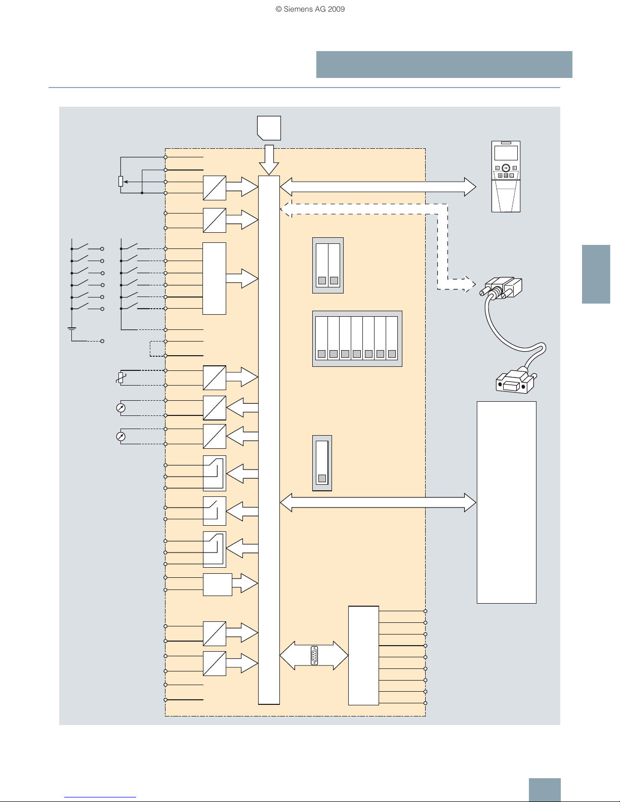
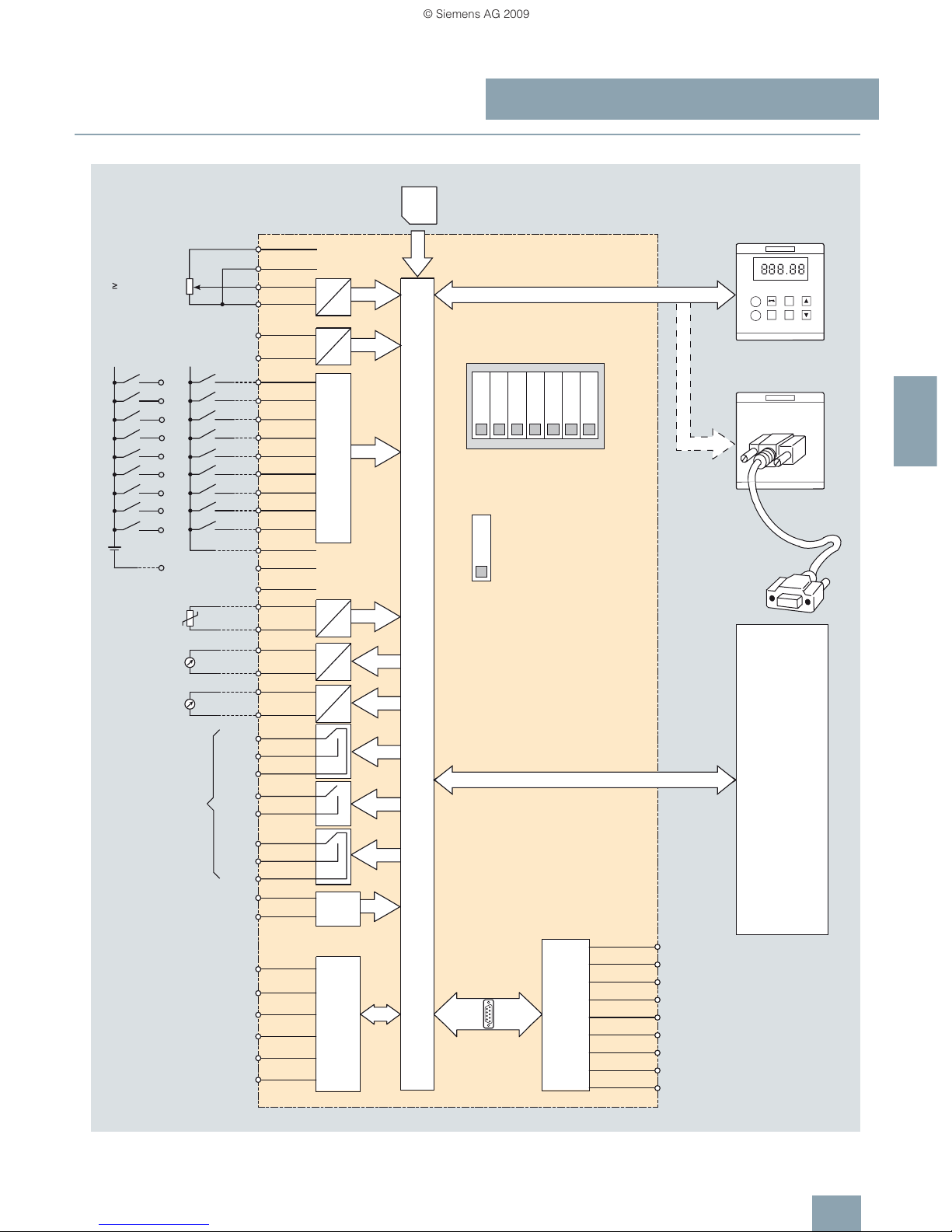
CU230P-2 HVAC Control Unit connection diagram
G_D011_EN_00210
IOP/IOP handheld
Shield
Voltage output 10 V
Temperature sensor
NI1000 or AI2+
Temperature sensor
NI1000 or AI3+
PM-IF interface
0 to 10 V
0 to 20 mA
PC to inverter
connection kit
OFF
ON
OFF
ON
0 to 20 mA
max. 500 Ohm
0 to 20 mA
max. 500 Ohm
≥ 4.7 kOhm
IOP/IOP handheld interface
USB interface for PC tools
Digital inputs
* = Not connected
RS485 connector
From
external
source
DIP switch
Bus termination
DIP switch
Analog inputs
NI1000
CURRENT
DIP switch
Temperature sensor NI1000
69
17
16
8
7
6
5
-
+
24 V
DI5
DI4
DI3
DI2
DI1
DI0
MMC
PTC/KTY
Power Module
AI1
AI0
DO0
DO2
DO1
AO1-27
AO1+26
D
A
D
A
5
4
3
2
0 V
RS485P
RS485N
*
1
0 V32
+24 V31
U0V28
NO21
COM22
NO24
NC23
COM25
NO19
NC18
COM20
AO0-13
AO0+12
15
14
69
U24V9
DI517
DI416
DI38
DI27
DI16
DI05
AI1-11
AI1+10
AI0-4
AI0+3
2
1
0 V
+ 10 V
D
A
A
D
A
D
GND
36
+ 10 V OUT
35
53
52
51
50
D
A
D
A
GND
GND
AI2+/
NI1000
AI3+/
NI1000
Control Unit
CU230P-2 HVAC
DI COM
© Siemens AG 2009
SINAMICS G120
Standard inverters 0.37 kW to 250 kW (0.5 hp to 400 hp)
CU230 Control Units
4/15
Siemens D 11.1 · 2009
4
■
Integration
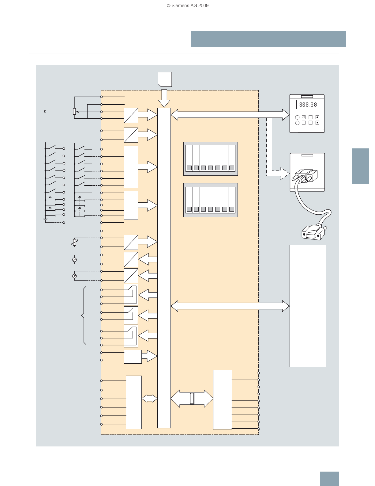
CU230P-2 DP Control Unit connection diagram
G_D011_EN_00211
IOP/IOP handheld
Shield/PE
Voltage output 10 V
Temperature sensor
NI1000 or AI2+
Temperature sensor
NI1000 or AI3+
PM-IF interface
0 to 10 V
0 to 20 mA
PC to inverter
connection kit
OFF
ON
OFF
ON
0 to 20 mA
max. 500 Ohm
0 to 20 mA
max. 500 Ohm
≥ 4.7 kOhm
IOP/IOP handheld interface
USB interface for PC tools
Digital inputs
* = Not connected
From
external
source
DIP switch
Analog inputs
NI1000
CURRENT
DIP switch
Temperature sensor NI1000
PROFIBUS address DIP switch
PROFIBUS interface
SUB-D connector
(1)
Bit 1
(64)(16) (32)(2) (4) (8)
Bit 0
Bit 3
Bit 2
Bit 5
Bit 6
Bit 4
69
17
16
8
7
6
5
-
+
24 V
DI5
DI4
DI3
DI2
DI1
DI0
MMC
PTC/KTY
Power Module
AI1
AI0
DO0
DO2
DO1
AO1-27
AO1+26
D
A
D
A
9
DPA8
7
6
5
4
DPB
RTS
0 V
5 V
*
*
*
3
2
1
0 V32
+24 V31
U0V28
NO21
COM22
NO24
NC23
COM25
NO19
NC18
COM20
AO0-13
AO0+12
15
14
69
U24V9
DI517
DI416
DI38
DI27
DI16
DI05
AI1-11
AI1+10
AI0-4
AI0+3
2
1
0 V
+ 10 V
D
A
A
D
A
D
GND
36
+ 10 V OUT
35
53
52
51
50
D
A
D
A
GND
GND
AI2+/
NI1000
AI3+/
NI1000
Control Unit
CU230P-2 DP
DI COM
© Siemens AG 2009
SINAMICS G120
Standard inverters 0.37 kW to 250 kW (0.5 hp to 400 hp)
CU230 Control Units
4/16
Siemens D 11.1 · 2009
4
■
Integration
CU230P-2 CAN Control Unit connection diagram
G_D011_EN_00212
IOP/IOP handheld
Voltage output 10 V
Temperature sensor
NI1000 or AI2+
Temperature sensor
NI1000 or AI3+
PM-IF interface
0 to 10 V
0 to 20 mA
PC to inverter
connection kit
OFF
ON
OFF
ON
OFF
ON
0 to 20 mA
max. 500 Ohm
0 to 20 mA
max. 500 Ohm
≥ 4.7 kOhm
IOP/IOP handheld interface
USB interface for PC tools
Digital inputs
* = Not connected
From
external
source
DIP switch
Analog inputs
CURRENT
DIP switch
Temperature sensor NI1000
CANopen address DIP switch
CANopen interface
SUB-D-type connector
DIP switch
Bus termination
(optional shield)
(optional CAN ground)
(1)
Bit 1
(64)(16) (32)(2) (4) (8)
Bit 0
Bit 3
Bit 2
Bit 5
Bit 6
Bit 4
69
17
16
8
7
6
5
-
+
24 V
DI5
DI4
DI3
DI2
DI1
DI0
MMC
PTC/KTY
Power Module
AI1
AI0
DO0
DO2
DO1
AO1-27
AO1+26
D
A
D
A
9
*8
7
6
5
4
CAN_GND
*
(CAN_SHLD)
(GND)
CAN_L
ISO
CAN_H
3
2
1
0 V32
+24 V31
U0V28
NO21
COM22
NO24
NC23
COM25
NO19
NC18
COM20
AO0-13
AO0+12
15
14
69
U24V9
DI517
DI416
DI38
DI27
DI16
DI05
AI1-11
AI1+10
AI0-4
AI0+3
2
1
0 V
+ 10 V
D
A
A
D
A
D
GND
36
+ 10 V OUT
35
53
52
51
50
D
A
D
A
GND
GND
AI2+/
NI1000
AI3+/
NI1000
DI COM
Control Unit
CU230P-2 CAN
NI1000
*
© Siemens AG 2009

SINAMICS G120
Standard inverters 0.37 kW to 250 kW (0.5 hp to 400 hp)
CU230 Control Units
4/17
Siemens D 11.1 · 2009
4
■
Technical specifications
Control Unit CU230P-2 HVAC
6SL3243-0BA30-1HA0
CU230P-2 DP
6SL3243-0BA30-1PA0
CU230P-2 CAN
6SL3243-0BA30-1CA0
Electrical specifications
Operating voltage 24 V DC from the Power Module or from the connection of an external power supply 18 ... 30 V DC
Current consumption Max. 0.5 A
Protective insulation PELV according to EN 50178
Protective separation from the line supply using double/reinforced insulation
Power loss <5.5 W
Interfaces
Digital inputs – Standard 6 isolated inputs, optically isolated;
free reference potential (own potential group)
NPN/PNP logic can be selected using the wiring
Switching level: 0 → 1: 11 V
Switching level: 1 → 0: 5 V
Max. input current 15 mA
Digital outputs
2 relay change-over contacts
250 V AC 2 A (inductive load), 30 V DC 5 A (ohmic load)
1 relay NO contact
30 V DC, 0.5 A (ohmic load)
Analog inputs
2 differential inputs,
switchable between voltage and current using DIP switch: –10 ... +10 V, 0/4 ... 20 mA, 10-bit resolution
1 non-isolated input,
switchable using DIP switch between current and temperature sensor, type NI1000/PT1000,
0/4 ... 20 mA; 10-bit resolution
1 non-isolated input,
temperature sensor, type NI1000/PT1000,
10-bit resolution
The two differential analog inputs can be configured as additional digital inputs.
Switching thresholds:
0 → 1: Rated voltage 4 V
1 → 0: Rated voltage 1.6 V
Analog inputs are protected against inputs in a voltage range of ±30 V and have a common-mode voltage in
the ±15 V range.
Analog outputs 2 non-isolated outputs,
switchable between voltage and current using parameter setting: 0 ... 10 V; 0/4 ... 20 mA
Voltage mode: 10 V, min. burden 10 kΩ
current mode: 20 mA, max. burden 500 Ω
The analog outputs have short circuit protection
PTC/KTY interface 1 motor temperature sensor input,
sensors that can be connected PTC, KTY and Thermo-Click,
accuracy ±5 °C
Bus interface
Type RS485 PROFIBUS DP CANopen
Protocols
USS
Modbus RTU
(switchable per software)
ProfiDrive profile V4.1 CANopen
Hardware
Te rm i na l
Insulated
USS: max. 187.5 kBaud
Modbus RTU:19.2 kBaud
bus terminating resistors can
be switched in
9-pin SUB-D connector
Insulated
Max. 12 Mbit/s
Slave address can be
set using DIP switches
9-pin SUB-D socket
Insulated
Max. 1 Mbit/s
Tool interfaces
Memory card 1 MicroMemoryCard
Operator panels IOP
supported connection options between CU230P and IOP: can be directly plugged on, door mounting or handheld
BOP not possible
PC interface USB
Open-loop/closed-loop control techniques
V/f linear/square/parameterizable ✓
V/f with flux current control (FCC) ✓
V/f ECCO linear/square ✓
Vector control, without encoder ✓
Vector control, with encoder –
Torque control, without encoder ✓
Torque control, with encoder –
© Siemens AG 2009

SINAMICS G120
Standard inverters 0.37 kW to 250 kW (0.5 hp to 400 hp)
CU230 Control Units
4/18
Siemens D 11.1 · 2009
4
■
Technical specifications
Control Unit CU230P-2 HVAC
6SL3243-0BA30-1HA0
CU230P-2 DP
6SL3243-0BA30-1PA0
CU230P-2 CAN
6SL3243-0BA30-1CA0
Software functions
Setpoint input ✓
Fixed frequencies 16, parameterizable
JOG ✓
Digital motorized potentiometer (MOP) ✓
Ramp smoothing ✓
Extended ramp-function generator
(with ramp smoothing Off3)
✓
Positioning down ramp –
Slip compensation ✓
Signal interconnection with BICO technology ✓
Free function blocks (FFB) for logic and
arithmetic operations
–
Switchable drive data sets (DDS)
✓ (4)
Switchable command data sets (CDS) ✓ (4)
Flying restart ✓
Automatic restart after line supply failure or
operating fault (AR)
✓
Technology controller (internal PID) ✓
Energy-saving function (hibernation)
with internal PID controller
✓
Energy-saving function (hibernation)
with external PID controller
✓
Belt monitoring with and without sensor
(load torque monitoring)
✓
Dry pump monitoring
(load torque monitoring)
✓
Thermal motor protection ✓ (I2t, sensor: PTC/KTY/Thermo-Click)
Thermal inverter protection ✓
Motor identification ✓
Motor holding brake –
Auto-ramping (V
dcmax
controller) ✓ (only with PM240 Power Module)
Kinetic buffering (V
dcmax
controller) ✓ (only with PM240 Power Module)
Braking functions for
•DC braking
• Compound braking
• Dynamic braking with integrated
brake chopper
✓ (only with PM240 Power Module)
Mechanical specifications and ambient conditions
Degree of protection IP20
Signal cable cross-section
•min. 0.15 mm2 (AWG28)
•max. 1.5 mm2 (AWG16)
Operating temperature –10 ... +60 °C
(14...140°F)
Storage temperature –40 ... +70 °C
(–40 ... +158 °F)
Relative humidity <95 % RH, condensation not permissible
Dimensions
• Width 73 mm
•Height 199 mm
•Depth 65.5 mm
Weight, approx. 0.61 kg
© Siemens AG 2009

SINAMICS G120
Standard inverters 0.37 kW to 250 kW (0.5 hp to 400 hp)
CU240 Control Units
4/19
Siemens D 11.1 · 2009
4
■
Overview
Example of CU240S DP-F Control Unit
The Control Unit performs closed-loop control functions for the
inverter. In addition to the closed-loop control, it has additional
functions that can be adapted to the particular application
through parameterization. Several Control Units are available in
different versions:
•CU240E
•CU240S
•CU240SDP
•CU240SDP-F
•CU240SPN
• CU240S PN-F
Safety Integrated functions
The following Safety Integrated functions are integrated in the
CU240S DP-F and CU240S PN-F Control Units and, with the exception of the “Safe Brake Control”, can be implemented without
external circuit elements:
The SINAMICS G120 fail-safe frequency inverter provides four
safety functions, certified in accordance with EN 954-1,
Category 3 and IEC 61508 SIL 2:
• Safe Torque Off (STO) to protect against active movement of
the drive
• Safe Stop 1 (SS1) for continuous monitoring of a safe braking
ramp
• Safely Limited Speed (SLS) for protection against dangerous
movements when a speed limit is exceeded
• Safe Brake Control (SBC) for controlling motor brakes that are
active in the de-energized state, e.g. motor holding brakes
The functions “Safe Stop 1” and “Safely Limited Speed” can
both be implemented without having to use a motor sensor or
encoder; the implementation cost is minimal. Existing systems in
particular can be simply updated with safety technology without
the need to change the motor or mechanical system.
The safety functions “Safely Limited Speed” and “Safe Stop 1”
are not certified for pull-through loads as in the case of lifting
gear and winders.
Safety functions have been extended with firmware V3.2.
Additional information is provided in the part Highlights, section
Safety Integrated.
■
Selection and ordering data
Communication Digital inputs
Standard
Digital inputs
Fail-safe
Digital outputs Encoder interfaces Designation Control Unit
Order No.
Standard
RS485/USS 6 – 3 – CU240E 6SL3244-0BA10-0BA0
RS485/USS 9 – 3 1 CU240S 6SL3244-0BA20-1BA0
PROFIBUS DP 9 – 3 1 CU240S DP 6SL3244-0BA20-1PA0
PROFINET 9 – 3 1 CU240S PN 6SL3244-0BA20-1FA0
Fail-safe for Safety Integrated
PROFIBUS DP 6 2 3 1 CU240S DP-F 6SL3244-0BA21-1PA0
PROFINET 6 2 3 1 CU240S PN-F 6SL3244-0BA21-1FA0
© Siemens AG 2009
SINAMICS G120
Standard inverters 0.37 kW to 250 kW (0.5 hp to 400 hp)
CU240 Control Units
4/20
Siemens D 11.1 · 2009
4
■
Design
CU240E Control Unit
CU240E Control Unit without terminal cover
Terminal No. Signal Features
Digital inputs (DI)
5…8,
16.17
DI0 … DI5 Freely programmable (isolated)
5.5 mA/24 V
Digital outputs (DO)
18 DO0, NC Relay output 1
NC contact (0.5 A, 30 V DC)
19 DO0, NO Relay output 1
NO contact (0.5 A, 30 V DC)
20 DO0, COM Relay output 1
Common contact (0.5 A, 30 V DC)
21 DO1, NO Relay output 2
NO contact (0.5 A, 30 V DC)
22 DO1, COM Relay output 2
Common contact (0.5 A, 30 V DC)
23 DO2, NC Relay output 3
NC contact (0.5 A, 30 V DC)
24 DO2, NO Relay output 3
NO contact (0.5 A, 30 V DC)
25 DO2, COM Relay output 3
Common contact (0.5 A, 30 V DC)
Analog inputs (AI)
3 AI0+ 0…10V, –10…+10V, 0/2…10V or
0/4 … 20 mA
4 AI010 AI1+ 0…10V, 0…20mA
11 AI1-
Analog outputs (AO)
12 AO0+ Freely programmable
(0/4 … 20 mA with max. 500 Ω,
0/2 … 10 V with min. 500 Ω)
13 AO0- M
26 AO1+ Freely programmable
(0/4 … 20 mA with max. 500 Ω)
27 AO1- M
PTC/KTY interface
14 PTC+ Positive PTC/KTY input
15 PTC- Negative PTC/KTY input
Serial RS485 interface
29 P+ RS485 A, USS protocol
30 N- RS485 B, USS protocol
Power supply
9 U24V Isolated user power supply
+24 V at 100 mA
28 U0V Isolated user reference voltage
1 +10 V Non-isolated, regulated
10 V power supply for I/O –
max. 10 mA
2 0V Power supply reference
© Siemens AG 2009
SINAMICS G120
Standard inverters 0.37 kW to 250 kW (0.5 hp to 400 hp)
CU240 Control Units
4/21
Siemens D 11.1 · 2009
4
■
Design
CU240S, CU240S DP, CU240S DP-F, CU240S PN and
CU240S PN-F Control Units
Example: CU240S DP-F Control Unit (right without terminal cover, with
pluggable terminals)
Terminal No. Signal Features
Digital inputs (DI) – Standard
5…8,
16.17
DI0 … DI5 Freely programmable (isolated)
5.5 mA/24 V
40 … 42
(only for
CU240S,
CU240S DP
and
CU240S PN)
DI6 … DI8 Freely programmable (isolated)
5.5 mA/24 V
Digital inputs (DI) – Fail-safe
(for CU240S DP-F and CU240S PN-F only)
60 … 63
(for
CU240S DP-F
and
CU240S PN-F
only)
FDI0A
FDI0B
FDI1A
FDI1B
Fail-safe digital inputs, 2 channels
(redundant),
freely programmable (isolated)
5.5 mA/24 V
Digital outputs (DO)
18 DO0, NC Relay output 1
NC contact (0.5 A, 30 V DC)
19 DO0, NO Relay output 1
NO contact (0.5 A, 30 V DC)
20 DO0, COM Relay output 1
Common contact (0.5 A, 30 V DC)
21 DO1, NO Relay output 2
NO contact (0.5 A, 30 V DC)
22 DO1, COM Relay output 2
Common contact (0.5 A, 30 V DC)
23 DO2, NC Relay output 3
NC contact (0.5 A, 30 V DC)
24 DO2, NO Relay output 3
NO contact (0.5 A, 30 V DC)
25 DO2, COM Relay output 3
Common contact (0.5 A, 30 V DC)
Terminal No. Signal Features
Analog inputs (AI)
3 AI0+ 0…10V, –10…+10V, 0/2…10V or
0/4 … 20 mA
4 AI0-
10 AI1+ 0…10V, 0…20mA
11 AI1-
Analog outputs (AO)
12 AO0+ Freely programmable
(0/4 … 20 mA with max. 500 Ω,
0/2 … 10 V with min. 500 Ω)
13 AO0- M
26 AO1+ Freely programmable
(0/4 … 20 mA with max. 500 Ω)
27 AO1- M
Encoder interface
70 ENC AP Encoder AP
Channel A non-inverting input
71 ENC AN Encoder AN
Channel A inverting input
72 ENC BP Encoder BP
Channel B non-inverting input
73 ENC BN Encoder BN
Channel B inverting input
74 ENC ZP Encoder ZP
Zero pulse non-inverting input
75 ENC ZN Encoder ZN
Zero pulse inverting input
PTC/KTY interface
14 PTC+ Positive PTC/KTY input
15 PTC- Negative PTC/KTY input
Power supply
33 ENC+
line supply
Isolated encoder power supply
(+24 V at 100 mA, +5 V at 300 mA),
configured using DIP switch
9
U24V Isolated user power supply
+24 V at 100 mA
28
U0V Isolated encoder power supply
and user reference voltage
1 +10 V Non-isolated, regulated
10 V power supply for I/O –
max. 10 mA
2 0V Power supply reference
31 +24 V 24 V power supply input
32 0V 24 V power supply reference
© Siemens AG 2009
SINAMICS G120
Standard inverters 0.37 kW to 250 kW (0.5 hp to 400 hp)
CU240 Control Units
4/22
Siemens D 11.1 · 2009
4
■
Integration
CU240E Control Unit connection diagram
ON
Low voltage only
(30 V, 500 mA)
Digital inputs
RS232/BOP interface
RS232 with
PC to inverter
connection kit
4.7 kOhm
0 to 20 mA
max. 500 Ohm
0 to 20 mA
max. 500 Ohm
PM-IF interface
OFF
0 to 20 mA
0 to 10 V
G_D011_EN_00183
DIP switch for
analog inputs
A
D
D
+ 10 V
0 V
1
2
3 AI0+
4 AI0-
10 AI1+
11 AI1 -
5 DI0
6 DI1
7 DI2
8 DI3
16 DI4
17 DI5
9 U24V
14 PTC+
15 PTC-
12 AO0+
13 AO0-
20 COM
18 NC
19 NO
25 COM
23 NC
24 NO
22 COM
21 NO
28 U0V
29
30
A
A
D
A
D
A
D
26 AO1+
27 AO1-
DO1
DO2
DO0
AI0
AI1
Power Module
PTC/KTY
JOG
BOP
Control Unit
CU240E
DI0
DI1
DI2
DI3
DI4
DI5
24 V
+
-
5
6
7
8
16
17
28
RS485
© Siemens AG 2009
SINAMICS G120
Standard inverters 0.37 kW to 250 kW (0.5 hp to 400 hp)
CU240 Control Units
4/23
Siemens D 11.1 · 2009
4
■
Integration
CU240S Control Unit connection diagram
A
D
A/
D
A/
D
+ 10 V
0 V
ENC+
1
2
3 AI0+
4 AI0-
10 AI1+
11 A I1-
5 DI0
6 DI1
7 DI2
8 DI3
16 DI4
17 DI5
40 DI6
41 DI7
42 DI8
9 U24V
33
14 PTC+
15 PTC-
12 AO0+
13 AO0-
20 COM
18 NC
19 NO
25 COM
23 NC
24 NO
22 COM
21 NO
28 U0V
31 +24 V
32 0V
71 ENC AN
70 ENC AP
1 *
2 *
3 RS485P
4 *
5 0 V
6 *
7 *
8 RS485N
9 *
72 ENC BP
73 ENC BN
74 ENC ZP
75 ENC ZN
A
D
A
D
A
D
A
D
26 AO1+
27 AO1-
DO1
DO2
DO0
AI0
AI1
Power Module
PTC/KTY
JOG
FN
I
P
O
BOP
Control Unit
CU240S
MMC
DI0
DI1
DI2
DI3
DI4
DI5
DI6
DI7
DI8
24 V
+
-
5
6
7
8
16
17
40
41
42
28
General I/O DIP switch
ON
5 V encoder
supply
24 V encoder
supply
Encoder A
termination
Encoder B
termination
Encoder Z
termination
Encoder interface
RS485
interface
SUB-D-type connector
Low voltage only
(30 V, 500 mA)
G_D011_EN_00114a
From
external
source
* = Not connected
Digital inputs
RS232/BOP interface
RS232 with
PC to inverter
connection kit
4.7 kOhm
0 to 20 mA
max. 500 Ohm
0 to 20 mA
max. 500 Ohm
Line
PM-IF interface
OFF
0 to 20 mA
0 to 10 V
Bus termination
DIP switch
ON
OFF
© Siemens AG 2009

SINAMICS G120
Standard inverters 0.37 kW to 250 kW (0.5 hp to 400 hp)
CU240 Control Units
4/24
Siemens D 11.1 · 2009
4
■
Integration
CU240S DP Control Unit connection diagram
A
D
A/
D
A/
D
+ 10 V
0 V
ENC+
1
2
3 AI0+
4 AI0-
10 AI1+
11 A I1-
5 DI0
6 DI1
7 DI2
8 DI3
16 DI4
17 DI5
40 DI6
41 DI7
42 DI8
9 U24V
33
14 PTC+
15 PTC-
12 AO0+
13 AO0-
20 COM
18 NC
19 NO
25 COM
23 NC
24 NO
22 COM
21 NO
28 U0V
31 +24 V
32 0V
71 ENC AN
70 ENC AP
1
2 U0V
3 RxD/TxD-P
4 CNTR-P
5 DGND
6 VP
7 U24V
8 RxD/TxD-N
9 *
72 ENC BP
73 ENC BN
74 ENC ZP
75 ENC ZN
A
D
A
D
A
D
A
D
26 AO1+
27 AO1-
DO1
DO2
DO0
(1) (2) (4) (8) (16) (32) (64)
AI0
AI1
Bit 0
Bit 1
Bit 2
Bit 3
Bit 4
Bit 5
Bit 6
Power Module
PTC/KTY
JOG
FN
I
P
O
BOP
Control Unit
CU240S DP
DI0
DI1
DI2
DI3
DI4
DI5
DI6
DI7
DI8
24 V
+
-
5
6
7
8
16
17
40
41
42
28
MMC
PROFIBUS address DIP switch
ON
General I/O DIP switch
ON
5 V encoder
supply
24 V encoder
supply
Encoder A
termination
Encoder B
termination
Encoder Z
termination
Encoder interface
PROFIBUS
interface
SUB-D-type connector
Shield
Low voltage only
(30 V, 500 mA)
G_D011_EN_00101
From
external
source
* = Not connected
Digital inputs
RS232/BOP interface
4.7 kOhm
0 to 20 mA
max. 500 Ohm
0 to 20 mA
max. 500 Ohm
Line
RS232 with
PC to inverter
connection kit
PM-IF interface
OFF
0 to 20 mA
0 to 10 V
OFF
© Siemens AG 2009
SINAMICS G120
Standard inverters 0.37 kW to 250 kW (0.5 hp to 400 hp)
CU240 Control Units
4/25
Siemens D 11.1 · 2009
4
■
Integration
CU240S DP-F Control Unit connection diagram
1
2
3
4
5
6
7
8
9*
4.7 kOhm
0 to 20 mA
max. 500 Ohm
0 to 20 mA
max. 500 Ohm
Low voltage only
(30 V, 500 mA)
Encoder interface
From
external
source
Safety
digital inputs
Standard
digital inputs
RS232/BOP interface
General I/O DIP switch
PROFIBUS address DIP switch
21
21
2))
2))
0 to 10 V
0 to 20 mA
24 V encoder
supply
5 V encoder
supply
Encoder A
termination
Encoder B
termination
Encoder Z
termination
PM-IF interface
PROFIBUS interface
SUB-D-type
connector
G_D011_EN_00102b
* = Not connected
RS232 with
PC to inverter
connection kit
Line
U0V
RxD/TxD-P
CNTR-P
DGND
VP
U24V
RxD/TxD-N
shield
60
61
62
63
+
Bit 0
Bit 1
Bit 3
Bit 4
Bit 5
Bit 6
Bit 2
(64)(32)(16)(8)(4)(2)(1)
1B
1A
FDI
62
0B
FDI61
MMC
28
40
17
16
8
7
6
5
-
24 V
DI6
DI5
DI4
DI3
DI2
DI1
DI0
Control Unit
CU240S DP-F
BOP
O
P
I
FN
JOG
PTC/KTY
Power Module
AI1
AI0
DO0
DO2
DO1
AO1-27
AO1+26
D
A
D
A
D
A
D
A
ENC ZN75
ENC ZP74
ENC BN73
ENC BP72
ENC AP70
ENC AN71
0V32
+24 V31
U0V
NO21
COM22
NO24
NC23
COM25
NO19
NC18
COM20
AO0-13
AO0+12
PTC-15
PTC+14
33
FDI
FDI 60
U24V9
DI5
17
DI416
DI38
DI27
DI16
DI05
AI1-11
AI1+
AI0-4
AI0+3
2
1
ENC+
0 V
+ 10 V
D
A
28
63
60
61
62
63
(64)(32)(16)(8)(4)(2)(1)
1B
1A
FDI
62
FDI61
MMC
28
40
17
16
8
7
6
5
-
DI6
DI5
DI4
DI3
DI2
DI1
DI0
Control Unit
CU240S DP-F
BOP
O
P
I
FN
JOG
AI1
AI0
DO0
DO2
DO1
AO1-27
AO1+26
D
A
D
A
D
A
D
A
ENC ZN75
ENC ZP74
ENC BN73
ENC BP72
ENC AP70
ENC AN71
0V32
+24 V31
U0V
NO21
COM22
NO24
NC23
COM25
NO19
NC18
COM20
AO0-13
AO0+12
PTC-15
PTC+14
33
FDI
FDI 0A60
U24V9
DI5
DI416
DI38
DI27
DI16
DI05
AI1-11
AI1+
AI0-4
AI0+3
2
1
ENC+
0 V
+ 10 V
D
A
28
63
10
© Siemens AG 2009
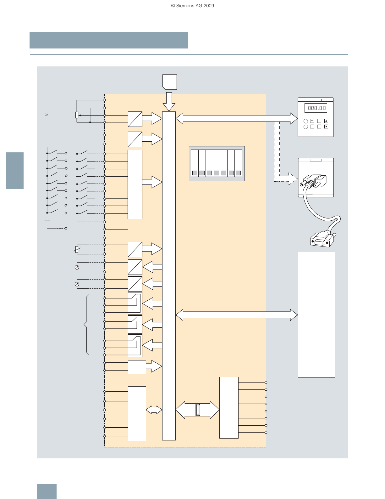
SINAMICS G120
Standard inverters 0.37 kW to 250 kW (0.5 hp to 400 hp)
CU240 Control Units
4/26
Siemens D 11.1 · 2009
4
■
Integration
CU240S PN Control Unit connection diagram
A
D
A/
D
A/
D
+ 10 V
0 V
ENC+
1
2
3 AI0+
4 AI0-
10 AI1+
11 A I1-
5 DI0
6 DI1
7 DI2
8 DI3
16 DI4
17 DI5
40 DI6
41 DI7
42 DI8
9 U24V
33
14 PTC+
15 PTC-
12 AO0+
13 AO0-
20 COM
18 NC
19 NO
25 COM
23 NC
24 NO
22 COM
21 NO
28 U0V
31 +24 V
32 0V
71 ENC AN
70 ENC AP
1
2 TX-
3 RX+
4 *
5 *
6 RX-
7 *
8 *
72 ENC BP
73 ENC BN
74 ENC ZP
75 ENC ZN
A
D
A
D
A
D
A
D
26 AO1+
27 AO1-
DO1
DO2
DO0
AI0
AI1
Power Module
PTC/KTY
JOG
FN
I
P
O
BOP
Control Unit
CU240S PN
DI0
DI1
DI2
DI3
DI4
DI5
DI6
DI7
DI8
24 V
+
-
5
6
7
8
16
17
40
41
42
28
MMC
TX+
General I/O DIP switch
ON
5 V encoder
supply
24 V encoder
supply
Encoder A
termination
Encoder B
termination
Encoder Z
termination
Encoder interface
PROFINET
interface
RJ45
Low voltage only
(30 V, 500 mA)
G_D011_EN_00119
From
external
source
* = Not connected
Digital inputs
RS232/BOP interface
4.7 kOhm
0 to 20 mA
max. 500 Ohm
0 to 20 mA
max. 500 Ohm
Line
RS232 with
PC to inverter
connection kit
PM-IF interface
OFF
0 to 20 mA
0 to 10 V
© Siemens AG 2009
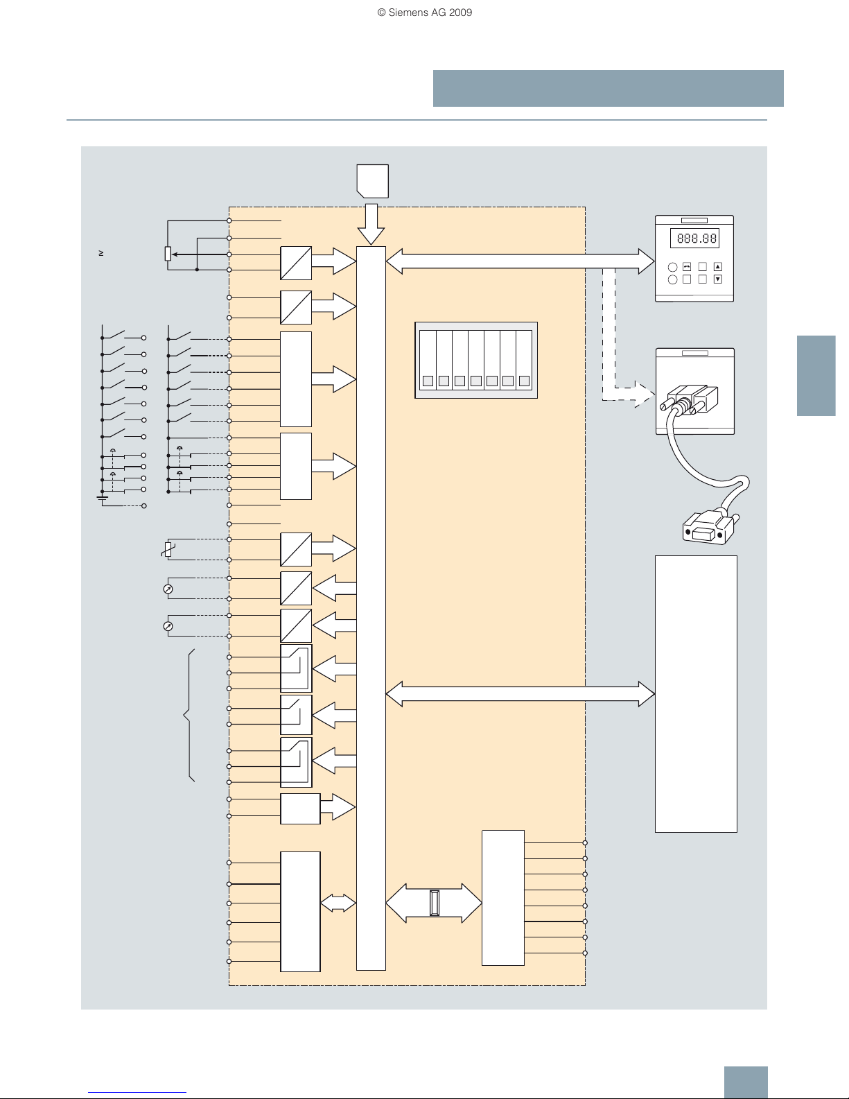
SINAMICS G120
Standard inverters 0.37 kW to 250 kW (0.5 hp to 400 hp)
CU240 Control Units
4/27
Siemens D 11.1 · 2009
4
■
Integration
CU240S PN-F Control Unit connection diagram
0 to 20 mA
max. 500 Ohm
0 to 20 mA
max. 500 Ohm
Line
4.7 kOhm
Standard
digital inputs
Safety
digital inputs
From
external
source
Encoder interface
PROFIBUS interface
RJ45
PM-IF interface
General I/O DIP switch
ON
OFF
0 to 20 mA
0 to 10 V
24 V encoder
supply
5 V encoder
supply
Encoder A
termination
Encoder B
termination
Encoder Z
termination
RS232/
BOP interface
RS232 with
PC to inverter
connection kit
* = Not connected
G_D011_EN_00184b
Low voltage only
(30 V, 500 mA)
60
61
62
63
1B
1A
FDI
62
0B
FDI61
TX+
MMC
28
40
17
16
8
7
6
5
-
+
24 V
DI6
DI5
DI4
DI3
DI2
DI1
DI0
Control Unit
CU240S PN-F
BOP
O
P
I
FN
JOG
PTC/KTY
Power Module
AI1
AI0
DO0
DO2
DO1
AO1-27
AO1+26
D
A
D
A
D
A
D
A
ENC ZN75
ENC ZP74
ENC BN73
ENC BP72
*8
*7
RX-6
*5
*4
RX+3
TX-2
1
ENC AP70
ENC AN71
0V32
+24 V31
U0V28
NO21
COM22
NO24
NC23
COM25
NO19
NC18
COM20
AO0-13
AO0+12
PTC-15
PTC+14
33
FDI63
FDI 0A60
U24V9
DI517
DI416
DI38
DI27
DI16
DI05
AI1-11
AI1+10
AI0-4
AI0+3
2
1
ENC+
0 V
+ 10 V
D
A
© Siemens AG 2009

SINAMICS G120
Standard inverters 0.37 kW to 250 kW (0.5 hp to 400 hp)
CU240 Control Units
4/28
Siemens D 11.1 · 2009
4
■
Technical specifications
Control Unit CU240E
6SL32440BA10-0BA0
CU240S
6SL32440BA20-1BA0
CU240S DP
6SL32440BA20-1PA0
CU240S PN
6SL32440BA20-1FA0
CU240S DP-F
6SL32440BA21-1PA0
CU240S PN-F
6SL32440BA21-1FA0
Electrical specifications
Operating voltage 24 V DC via the
Power Module
24 V DC via the
Power Module or
external 24 V DC
24 V DC via the
Power Module or
external 24 V DC
24 V DC via the
Power Module or
external 24 V DC
24 V DC via the
Power Module or
external
24 V DC
24 V DC via the
Power Module or
external
24 V DC
Current drain from the
24 V supply
Available soon Max. 0.5 A Max. 0.5 A Max. 0.7 A Max. 0.7 A Max. 0.7 A
Power loss (full load) <5.5W <5.5W <5.5W <13W <16W <17W
Interfaces
Digital inputs – Standard 6 9 9 9 6 6
Digital inputs – Fail-safe – – – – 2 2
Digital outputs 3 3 3 3 3 3
Analog inputs 2 2 2 2 2 2
Both analog inputs can be configured as supplementary digital inputs if an additional function is required.
Switching thresholds:
0 → 1: Rated voltage 2 V
1 → 0: Rated voltage 0.8 V
Analog inputs are protected against inputs in a voltage range of ±30 V and have a common-mode voltage in
the ±15 V range.
Analog outputs 2 2 2 2 2 2
Analog outputs have short-circuit protection, but are not isolated.
Maximum output voltage = 10 V in the current mode,
maximum output current = 20 mA in the voltage mode.
The response time should be approximately 1 ms at a load of max. 10 kΩ in the voltage mode.
Bus interface RS485/USS RS485/USS PROFIBUS DP PROFINET PROFIBUS DP,
PROFIsafe
PROFINET,
PROFIsafe
Encoder interfaces – 1 1 1 1 1
PTC/KTY interface ✓ ✓ ✓ ✓ ✓ ✓
Brake Relay interface or
Safe Brake Relay interface
(connected via Power Module)
✓ ✓ ✓ ✓ ✓ ✓
MMC memory card slot – ✓ ✓ ✓ ✓ ✓
Operator panels that can be used BOP, IOP Hand-
held (via PC
Inverter Connection Kit)
BOP, IOP Handheld (via PC
Inverter Connection Kit)
BOP, IOP Handheld (via PC
Inverter Connection Kit)
BOP, IOP Handheld (via PC
Inverter Connection Kit)
BOP, IOP Handheld (via PC
Inverter Connection Kit)
BOP, IOP Handheld (via PC
Inverter Connection Kit)
RS232/USS interface
(connection via PC Inverter
Connection Kit)
✓ ✓ ✓ ✓ ✓ ✓
Safety functions
Integrated safety functions acc. to
Category 3 of EN 954-1 and acc. to
SIL 2 of IEC 61508
– – – – • Safe Stop 1 (SS1)
• Safely Limited Speed (SLS)
• Safe Brake Control (SBC)
• Safe Torque Off (STO)
Open-loop/closed-loop control techniques
V/f linear/square/parameterizable ✓ ✓ ✓ ✓ ✓ ✓
V/f with flux current control (FCC) ✓ ✓ ✓ ✓ ✓ ✓
Vector control, without encoder ✓ ✓ ✓ ✓ ✓ ✓
Vector control, with encoder – ✓ ✓ ✓ ✓ ✓
Torque control, without encoder ✓ ✓ ✓ ✓ ✓ ✓
Torque control, with encoder – ✓ ✓ ✓ ✓ ✓
© Siemens AG 2009

SINAMICS G120
Standard inverters 0.37 kW to 250 kW (0.5 hp to 400 hp)
CU240 Control Units
4/29
Siemens D 11.1 · 2009
4
■
Technical specifications
Control Unit CU240E
6SL32440BA10-0BA0
CU240S
6SL32440BA20-1BA0
CU240S DP
6SL32440BA20-1PA0
CU240S PN
6SL32440BA20-1FA0
CU240S DP-F
6SL32440BA21-1PA0
CU240S PN-F
6SL32440BA21-1FA0
Software functions
Fixed frequencies 16,
parameterizable
16,
parameterizable
16,
parameterizable
16,
parameterizable
16,
parameterizable
16,
parameterizable
Signal interconnection
with BICO technology
✓ ✓ ✓ ✓ ✓ ✓
Automatic restart after line supply
failure or operational fault
✓ ✓ ✓ ✓ ✓ ✓
Positioning down ramp ✓ ✓ ✓ ✓ ✓ ✓
Slip compensation ✓ ✓ ✓ ✓ ✓ ✓
Free function blocks (FFB)
for logic and arithmetic operations
✓ ✓ ✓ ✓ ✓ ✓
Ramp smoothing ✓ ✓ ✓ ✓ ✓ ✓
3 selectable drive data sets ✓ ✓ ✓ ✓ ✓ ✓
3 selectable command data sets
(CDS) (manual/auto)
✓ ✓ ✓ ✓ ✓ ✓
Flying restart ✓ ✓ ✓ ✓ ✓ ✓
JOG ✓ ✓ ✓ ✓ ✓ ✓
Technology controller (PID) ✓ ✓ ✓ ✓ ✓ ✓
Thermal motor protection ✓ ✓ ✓ ✓ ✓ ✓
Thermal inverter protection ✓ ✓ ✓ ✓ ✓ ✓
Setpoint input ✓ ✓ ✓ ✓ ✓ ✓
Motor identification ✓ ✓ ✓ ✓ ✓ ✓
Motor holding brake ✓ ✓ ✓ ✓ ✓ ✓
V
dcmax
controller ✓
(only with
PM240)
✓
(only with
PM240)
✓
(only with
PM240)
✓
(only with
PM240)
✓
(only with
PM240)
✓
(only with
PM240)
Kinetic buffering ✓
(only with
PM240)
✓
(only with
PM240)
✓
(only with
PM240)
✓
(only with
PM240)
✓
(only with
PM240)
✓
(only with
PM240)
Braking functions for
•DC braking
• Compound braking
• Dynamic braking with integrated
brake chopper
✓
(only with
PM240)
✓
(only with
PM240)
✓
(only with
PM240)
✓
(only with
PM240)
✓
(only with
PM240)
✓
(only with
PM240)
Mechanical specifications and ambient conditions
Degree of protection IP20 IP20 IP20 IP20 IP20 IP20
Signal cable cross-section
•min. 0.05 mm2
(AWG30)
0.05 mm2
(AWG30)
0.05 mm2
(AWG30)
0.05 mm2
(AWG30)
0.05 mm2
(AWG30)
0.05 mm2
(AWG30)
•max. 2mm2 (AWG14) 2mm2 (AWG14) 2mm2 (AWG14) 2mm2 (AWG14) 2mm2 (AWG14) 2mm2 (AWG14)
Operating temperature –10 … +50 °C
(14…122°F)
–10…+50°C
(14…122°F)
–10 … +50 °C
(14…122°F)
–10…+50°C
(14…122°F)
0 … 45 °C
(32…113°F)
0 … 40 °C
(32 … 104 °F)
Storage temperature –40 … +70 °C
(–40 … +158 °F)
–40…+70°C
(–40 … +158 °F)
–40 … +70 °C
(–40 … +158 °F)
–40…+70°C
(–40 … +158 °F)
–40…+70°C
(–40 … +158 °F)
–40…+70°C
(–40 … +158 °F)
Relative humidity <95% RH,
condensation
not permissible
<95% RH,
condensation
not permissible
<95% RH,
condensation
not permissible
<95% RH,
condensation
not permissible
<95% RH,
condensation
not permissible
< 95 % RH,
condensation
not permissible
Dimensions
• Width 73 mm 73 mm 73 mm 73 mm 73 mm 73 mm
•Height
195 mm 177 mm 177 mm 177 mm 177 mm 177 mm
•Depth 31 mm 63 mm 63 mm 63 mm 63 mm 63 mm
Weight, approx. 0.21 kg 0.52 kg 0.52 kg 0.52 kg 0.52 kg 0.52 kg
© Siemens AG 2009

SINAMICS G120
Standard inverters 0.37 kW to 250 kW (0.5 hp to 400 hp)
PM240 Power Modules –
0.37 kW to 250 kW (0.5 hp to 400 hp)
4/30
Siemens D 11.1 · 2009
4
■
Overview
Example: SINAMICS G120, frame sizes FSA to FSF
Example: SINAMICS G120, frame size FSGX
PM240 Power Modules, frame sizes FSA to FSF have an integrated brake chopper to which an external braking resistor can
be connected via terminals DCP/R1 and R2 (see DC link components).
PM240 Power Modules, frame size FSGX do not have an integrated brake chopper. For these devices, there is an optional
pluggable braking module to connect a braking resistor.
The PM240 Power Module can be used to couple the DC links of
up to 10 Power Modules. This functionality is used for applications such as safe power-down after power failure or kinetic buffering (the DC link is supplied in the generator mode with the kinetic energy of the load so that the DC link voltage can be
maintained).
The PM240 Power Module is also designed for safety-oriented
applications. In conjunction with a Fail-safe Control Unit, the
drive can be turned into a Safety Integrated Drive (see Control
Units).
The permissible cable lengths between inverter and motor are
limited. Longer cables can be used if output reactors are connected (see load-side power components).
Line reactors are available to minimize line harmonics (see lineside components).
Frame size FSA of the PM240 Power Module is available only
without integrated line filter to class A. A base filter is therefore
available so that class A can be achieved. A class B base filter
is also available so that class B can be achieved (see line-side
power components).
Frame sizes FSB and FSC of the PM240 Power Module are available both with and without integrated class A line filter. For compliance with class B, PM240 Power Modules with integrated
class A line filter must be fitted additionally with a class B base
filter (see line-side components).
Power Modules with integrated class A line filter are suitable for
connection to TN supply systems. Power Modules without integrated line filter can be connected to grounded (TN, TT) and
non-grounded (IT) supply systems.
© Siemens AG 2009
 Loading...