

Simuline Cycraft Installation & User Manual
G426601E REV1.2
INSTALLATION & USER MANUAL
l
l
l
To use this machine safely and correctly, read this manual carefully.
After reading this manual, be sure to keep it available nearby the product or
somewhere convenient so that it can be referred to whenever necessary.
When transporting or reselling this product, be sure to attach this manual to
the product.
© 2003, Simuline. Inc
Page 2
BEFORE USING THIS PRODUCT
Thank you for purchasing our arcade use simulator equipment “CYCRAFT” game
machine.
Safety notes:
To ensure the safe usage of the product, be sure to read the following before using this
product. The following instructions are intended for the users, operators and the
personnel in charge of the operation of the product.
After carefully reading and sufficiently understanding the warning displays and cautions,
handle the product appropriately. Be sure to keep this manual available nearby the
product or somewhere convenient so that it can be referred to whenever necessary.
In this manual, explanations, which require special attention, are enclosed with dual lines.
Depending on the degree of potential hazards, the terms of DANGER, WARNING,
CAUTION, etc. are used.
Be sure to understand the contents of the displays before reading the text.
Indicates that mishandling the
product by disregarding the
instructions can cause severe
injury.
Indicates that mishandling the
product by disregarding the
instructions can cause a slightly
hazardous situation that can result
in light personal injury and or
material damage.
Indicates that mishandling the
product by disregarding the
instructions can cause a
potentially hazardous situation
that can result in serious injury.
For the safe usage of the product, the following pictographs are used:
Indicates, “HANDLE WITH CARE”. In order to protect personnel and equipment,
this display is attached to places where the Owner’s manual and or Service
Manual should be referred.
Indicates a “Protective Earth Terminal”. Before operating the equipment, be sure
to connect it to the Earth line.

Page 3
Perform work in accordance with the instruction herein stated.
Follow instructions carefully paying special attention from the standpoint of accident
prevention. Failure to follow instructions can cause accidents. Instructions will point out
those jobs requiring trained technicians or servicemen.
Before installing the product, check for the electrical specification sticker.
SIMULINE products have a sticker on which the electrical specifications are detailed.
Ensure that the product is compatible with the power supply voltage and frequency
requirements of the location in which the machine is to be installed.
Install and operate the product only in places where appropriate and sufficient
lighting is available such that warning stickers can be clearly read.
Be sure to turn off power before working on the machine.
To prevent electric shock, be sure to turn off power before starting any work in which the
worker is exposed to the interior of the product.
Exercise great care when handling the monitor.
Some of the monitor parts are subjected to high-tension voltage. Even after turning the
power off, some components retain high-tension voltage. Only qualified service engineers
should perform monitor repair and replacement.
Be sure to adjust the monitor properly.
Do not operate the product with on-screen flickering or blurring unadjusted. Using the
product with the monitor not properly adjusted may cause dizziness or a headache to an
operator, a player, or the customers.
Specification changes, removal of equipment, conversion and or additions not
designated by SIMULINE is not allowed.
Do not make any engineering changes by alterations, unauthorized parts replacements or
other modifications under any circumstances. Should doors, lids and protective parts be
damaged or lost, refrain from operating the product, and contact the office where the
product was purchased from or the office of Simuline given in this manual.
SIMULINE shall not be held responsible for any accidents, compensation for damage to a
third party, resulting from unauthorized changes and modifications to the product.
When transporting or reselling this product, be sure to attach this manual to the
product.
*Descript ion herein cont ained may be subjected to improvem ents and changes without notice
**The contents described herein are fully prepared with due care. However, should any question ar ise or errors be found,
please contact SIMULINE.
Page 4
INTRODUCTION OF THIS INSTALLATION & SERVICE MANUAL
This manual is intended to provide detailed descriptions together with all the necessary
information covering the general operation of electronic assemblies, electro mechanicals,
servicing control, spare parts, etc. for the product, CYCRAFT.
This manual is intended for the owners, personnel and managers in charge of operation
of the product. Operate the product after carefully reading and sufficiently understanding
the instructions. If the product fails to function satisfactorily, non-technical personnel
should under no circumstances touch the internal system. Please contact office where the
product was purchased.
Use of this product is unlikely to cause physical injuries or damages to property. However,
where special attention is required “IMPORTANT” symbol and message is given in the
manual as follows:
Indicates that mishandling the product by disregarding this message can cause
performance degradation or malfunctions.
DEFINITION OF PERSONNEL IN THIS MANUAL:
Non-technical personnel who do not have technical knowledge and expertise
should refrain from performing such work that this manual requires the arcade
maintenance personnel or a serviceman to carry out, or work, which is not
explained in this manual. Failing to comply with this instruction can cause severe
accidents such as electric shock.
Ensure that the arcade maintenance personnel or a serviceman performs parts
replacement, servicing & inspections, and troubleshooting. It is instructed herein that the
serviceman who has technical expertise and professional knowledge in the field should
perform particularly hazardous work.
The following definitions for personnel are used in this manual:
l Arcade maintenance personnel
Those who have experience in the maintenance of amusement equipment and
vending machines, etc. and also participate in the servicing and control of the
equipment through such routine work as equipment assembly and installation,
inspections, and replacement of parts and consumables, etc. within the amusement
facilities and or locations under the management of the owner and owner’s operators
of the product.

Page 5
l Service Person
Those who carry out inspections and maintenance services of the CYCRAFT
should be under the authorization of Simuline Inc or Sega (Japan / Europe / USA)
It is mandatory that the Service Person must have technical expertise
equivalent to that of technical high school graduates in the fields of electricity,
electronics and or mechanics.
l Player
Persons who play games at facilities and shops where arcade amusement game
machines are installed.
l Gallery
Persons who are onlookers near the games at facilities and shops where arcade
amusement game machines are installed.
REVISION RECORDS:
Language: English
Rev: 1.2
Modified Date: December 2003 (gb / sk / esk)
O/S Version: 1.64
Game Version: BGD0
PLACE TO BE CONTACTED:
For necessary repairs and parts, contact the Distributor whom you purchased your Cycraft.
SIMULINE, INC / CUSTOMER SERVICE
461-28
Jeon-Min-Dong
Yu-Sung-Gu
Deajeon
Korea
305-811
Phone: +82-42-610-1010
Fax: +82-42-862-0795
E-mail: sales@simuline.com
Web-Site: www.simuline.com

Page 6
TABLE OF CONTENTS
BEFORE USING THE PRODUCT.
1. PRODUCT SPECIFICATION
1.1 GENERAL SPECIFICATION
1.2 MOTION SYSTEM DESCRIPTION
1.3 SAFETY SYSTEM DESCRIPTION
2. INITIAL INSPECTION
3. NAMES OF MAJOR PARTS
4. TRANSPORTING AND MOVING
4.1 EQUIPMENT REQUIRED FOR UNLOADING AND TRANSPORT
4.2 UNLOADING AND OPENING THE CRATE
4.3 UNPACKING AND INSTALLING REAR CASTER WHEELS
4.4 MOVING THE MACHINE
5. INSTALLATION INSTRUCTION.
5.1 LOCATION REQUIREMENTS
5.1.1 ENVIRONMENT REQUIREMENTS
5.1.2 ELECTRICAL REQUIREMENTS
5.2 EQUIPMENT REQUIRED FOR INSTALLATION
5.3 STEPS FOR INSTALLATION
5.4 SECURING IN PLACE (LEG ADJUSTER ADJUSTMENT)
5.5 CONNECTING THE HEAVE ACTUATOR
5.6 CONNECTING THE SAFETY LINK
5.7 ASSEMBLING THE FLOOR SENSOR PLATES
5.8 SETTING THE PHOTO SENSORS
5.9 COIN MECHANISM INSTALLATION
5.10 CONNECTING THE ELECTRIC POWER SOURCE
5.11 POST INSTALLATION TESTING AND INSPECTION
5.11.1 TESTING AND ALIGNING THE PHOTO SENSORS
5.11.2 TESTING AND ADJUSTING THE FLOOR PRESSURE SENSOR
5.12 ASSEMBLING THE FENCE
5.13 FIGURE OF CYCRAFT AFTER FINISHING THE INSTALLATION WORK

Page 7
6. OPERATION & ADJUSTMENT INSTRUCTION
6.1 DESCRIPTION OF INDICATORS AND SWITCHES ON THE OPERATION
PANEL
6.2 TURNING THE POWER ON AND OFF
6.3 ADJUSTMENT OF THE SPEAKER VOLUMES
6.4 SETTING VIDEO MONITOR PARAMETERS
6.5 USING THE LCD PANEL TO SET CONFIGURATIONS
6.5.1 SETTING THE SAFETY SENSOR PARAMETERS
6.5.2 SETTING TCP/IP CONFIGURATION
6.5.3 VIEW ING THE TOTAL COIN COUNT (STATISTICS)
6.6 SETTING THE COIN AND CREDIT CONFIGURATION
6.7 GAME PLAY OPERATION
7. MAINTENANCE & INSPECTION INSTRUCTION
7.1 ROUTINE MAINTENANCE
7.2 INSPECTION OF CRITICAL BOLTS AND CONNECTIONS
7.3 VERIFICATION OF SNAP RINGS
7.4 CHECKING WELD CONDITION
7.5 CHECKING THE ACTUATOR DRIVE BELT
7.6 CLEANING THE MSCU AIR FILTERS AND FAN
7.7 LUBRICATING THE ACTUATORS
7.8 LUBRICATING THE JOINTS
8. SERVICE & REPLACEMENT INSTRUCTION
8.1 EXCHANGING THE COMPACT FLASH CARD
8.2 REPLACEMENT OF SERVO CONTROLLER BOARD
9. TROUBLE SHOOTING
9.1 TROUBLESHOOTING TABLE
9.2 CONTROLLER ERROR MESSAGE TABLE
10. ELECTRIC SCHEMATICS
10.1 SCU SCHEMATIC
10.2 CABIN SCHEMATIC
10.3 MCU SCHEMATIC
Page 8
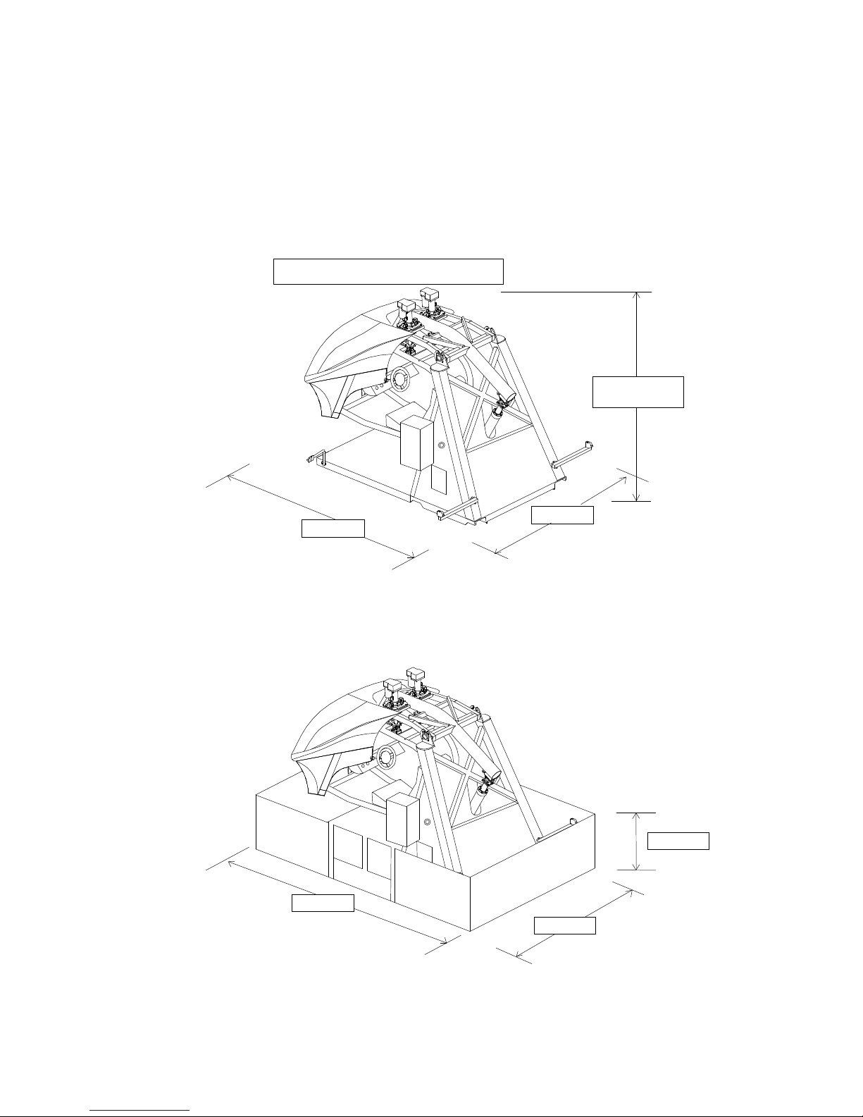
1. PRODUCT SPECIFICATIONS
1.1 GENERAL SPECIFICATIONS
2150 mm
2870 mm
Approximately
2200 mm
When the cabin is at the power- on position
2900 mm
1000 mm
4050 mm

Page 9
Category Coin-op interactive motion simulator
Play type Arcade game
Main Machine Dimensions
(At the power-on position.)
2870 mm (L) × 2150 mm (W) × ~ 2200 mm (H)
Main Machine Dimensions
(Transport dimensions)
2890 mm (L) × 1540 mm (W) × 2020 mm (H)
Fence Dimensions 4050 mm (L) × 2900 mm (W) × 1000 mm (H)
Weight Main Machine: (Approximately) 900 kg
Fence: (Approximately) 110 kg
Electric Power Single phase AC 200/208/220/230/240 V,
50/60 Hz, (Max) 10A
No. Of Passenger Single Player
Passenger Weight Limit 120 Kg
Compartment Semi-enclosed with seat belt
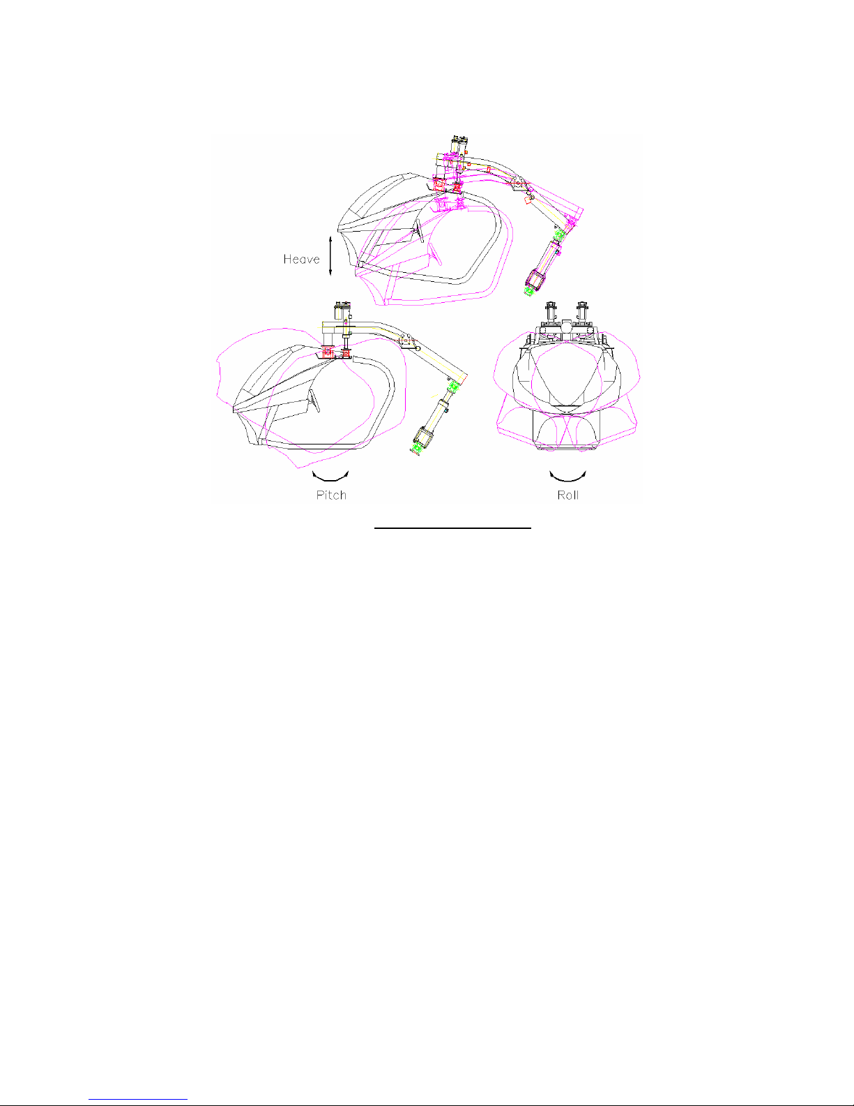
1.2 MOTION SYSTEM DESCRIPTION
The motion actuation system used in Cycraft is a very unique, high tech system that
distinguishes Cycraft from other simulator products. The motion system has the
following special features:
l Fully electric motion system: The actuators are fully Electrical (no hydraulics),
making it superior in terms of maintainability and transportability.
l Patented “inverted” configuration (virtual 5 DOF system): The motion
actuators are configured such that pitch and roll rotational motions have their center of
rotations above the passenger. This patented technology enables the simulator to
produce the effects of a 5 X DOF (degrees of freedom) motion system although it has
only 3 DOF mechanically. Therefore, fast and accurate motion cueing is made
possible without increasing costs.
Page 10
3 DOF Motion Systems
The heave actuator produces up/down heave motion by rocking the rocker arm, which
holds the passenger cabin. The two suspended actuators on the rocker arm
assembly produce the relative pitch and roll motions
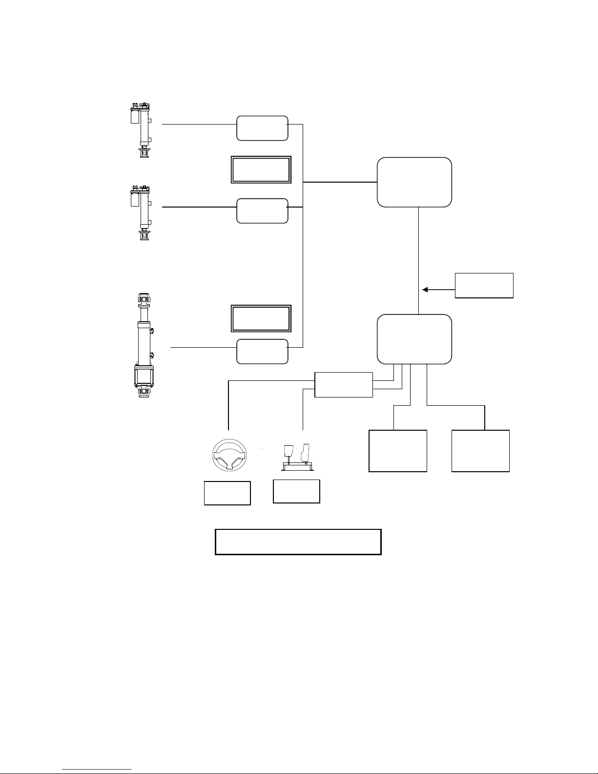
Separate controllers inside the MSCU control each of the linear actuators. The
controllers are in turn connected to the motion controller board, which generates the
commands for each actuator via high-speed industrial Control Area Network (CAN)
cable.
During the game, the game computer regularly sends the attitude data and other
dynamic properties data in real time to the motion control computer. The motion
board then calculates in real time, the motion necessary to give the passenger the
best feeling of reality and converts this motion to commands for the motion controllers
and actuators.
Page 11
TCPIP
CAN NETWORK
Servo Control
Board #3
Servo Control
Board #2
Servo Control
Board #1
Motion Computer
3 x Boards
Flash Rom Fitted
Sega Game System
NAOMI 2 or Triforce,
Dimm Bd, GD Rom
Drive, I/O Bd, PSU.
Game
Monitor
Audio
System
Handle
Pedal
SYSTEM DIAGRAM OF CYCRAFT
LAN cable
I / O Board
Toshiba
Mitsubishi

Page 12
1.3 SAFETY SYSTEM FEATURES
Operators of Cycraft should familiarize themselves with the safety features of Cycraft
to ensure that they are functioning properly for safe and proper operation. Cycraft
incorporates a number of safety features to ensure that accidents and injury will not be
caused to passengers and on-lookers due to the motion of the simulator. Following
is a description of each safety feature.
l Fence: A sturdy metal fence with an entrance door is provided with Cycraft. It will
ensure that on-lookers and waiting players will be kept a safe distance from the moving
cabin. The fence will also prevent on-lookers from approaching too closely and
unnecessarily tripping the photo sensors during play. Warning signs and regulation
signs are attached to the fence and door to inform customers and on-lookers.
l Side Photo Sensor: Two photo sensors attached on either side of the outer frame
of Cycraft cause the motion to stop if any obstacle obstructs the line between the
sensor and the reflective plate during play. Therefore, even if people enter the fence
and approach Cycraft when it is moving, safety is ensured since the photo sensor will
be tripped and motion stopped. Motion resumes 3 seconds after the obstacle is
removed.
l Floor Sensor: The floor plate beneath the cabin (seat) is a pressure sensor, which
activates when stepped on. It is guaranteed to detect pressures above 20 kg.
Activation of the floor sensor will stop the Cycraft motion as with the photo sensors
described above. Motion will re-activate 3 seconds after the pressure is removed.
The floor sensor guarantees safety even in the case when people somehow approach
Cycraft without tripping the photo sensor and also in the case when the passenger falls
from the cabin during play for any reason.
l Seat Belt Sensor: The seat belt buckle in Cycraft is equipped with a sensor that
detects when the seat belt is fastened or not. Cycraft will not start the game unless
the seat belt is fastened properly. Also, if the seat belt is unfastened during the game,
the motion will stop until it is re-fastened.
l Game Stop Button: This button, located inside the cabin allows the player to stop
the game anytime during play. Pressing this button will terminate the game and lower
the cabin to the initial position.
l Motion Stop Switch: The motion stop button located behind the coin chute case
stops the motion when pressed. Motion restarts 3 seconds after the button is
released. This button can be pressed by outside on-lookers or by the operator in

Page 13
case the photo or floor sensors cannot be activated or the motion must be stopped for
safety reasons.
l Power Cutoff Switch: This button located inside the operator panel but accessible
through a sliding door on the operator panel cover shuts off the main power to the
system. Pressing this switch will stop the ongoing motion of the system but will not
stop and hold the position of the cabin as with the other buttons and safety features.
Instead, the cabin will slowly pitch forward (nose down) and glide down to its lowest
position due to its own weight. Therefore, this switch should NOT be pressed
when the motion needs to be stopped. This switch should only be used in the rare
emergency case when power must be cut off such as when a fire is ignited.
NEVER press the power cutoff switch when there is a person or obstacle
UNDER the cabin. The cabin will glide down after the switch is pressed and
can cause serious injury to anybody under the cabin.
l Safety Link (page 29) and Safety Oriented Mechanical Design: The safety link
located on the rear part of the rocker arm functions to prevent a free fall of the cabin in
case the heave actuator is broken off from the rocker arm. The two rocker arm
bearings and center shaft of the rocker arm is designed such that even if one of the
bearings comes loose, the shaft will be held up by the frame to prevent a fall. The
cabin is suspended by three universal joints (central joint and two joints connecting to
the actuators). Therefore, even if one of the joints fail, the other two will support the
cabin to prevent a complete free fall.
l Other Safety Features: Cycraft is equipped with Brake Boards to supply step down
voltages to critical motor controller circuits, in case of power outages so that the cabin
(seat) does not fall abruptly. At power outages (and also when the power cutoff switch
is pressed) the motor control circuits with brake boards will make sure that the
simulator will shutdown and rest softly.
l Safe Inherent Design: The basic configuration of the inverted motion system allows
for the cabin to be suspended much lower from the ground than conventional motion
simulators. Also, it is dynamically much more stable by making it very difficult to tip
the cabin over to it’s side. Thus, the Cycraft structural design is inherently much safer
than conventional motion simulators.
Page 14
INITIAL INSPECTION
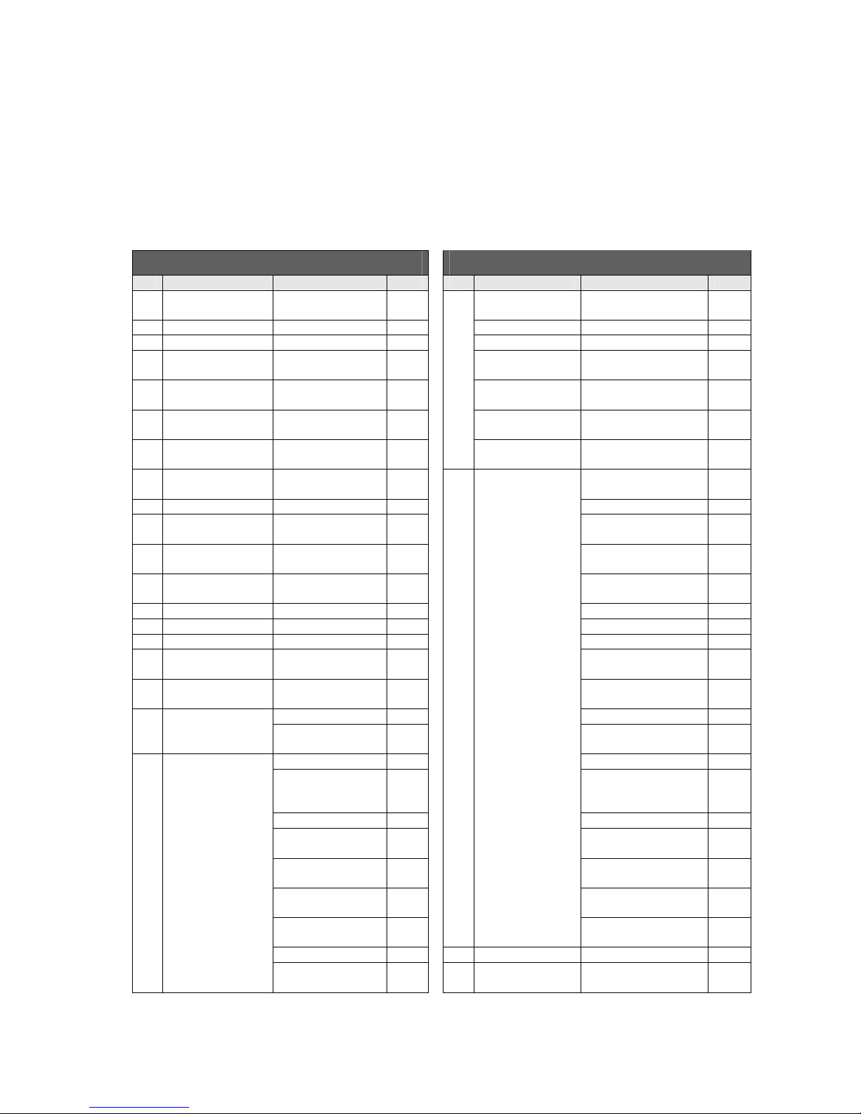
2.1 PACKING LIST
CYCRAFT PACKING LIST (1/2) CYCRAFT PACKING LIST (2/2)
No Item Description Qty No Item Description Qty
1
CYCRAFT Main
Body
1 ea 19 Hex Bolt M8x20L 10 ea
2 Rear C aster (R) 1 ea Hex Nut M8 7 ea
3 Rear Caster (L) 1 ea Clam ping Filter 1 ea
4
Floor Sensor Plate
(A)
A Type 1 ea Fence Sign Plate 4 ea
5
Floor Sensor Plate
(B)
B Type 1 ea
Fence Sign Ring
Clip
8 ea
6
Floor Sensor Plate
(C)
C Type 1 ea
Play Instruction
Sticker
1 set
7
Floor Sensor Plate
(D)
D Type 1 ea
Installation & User
Manual
1 ea
8 Boarding Step 1 ea 20 Spare Parts Box
Floor Sensor
Micro switch
2 ea
9 Coin Chute Tower 1 ea Monitor BD Fuse 1 ea
10
Fence Holding
Bracket (A)
1030 mm 1 ea Cable Tie 5 ea
11
Fence Holding
Bracket (B)
690 mm 1 ea Pushbutton Lamp 2 ea
12
Fence Holding
Bracket (C)
550 mm 1 ea Grease Gun 1 ea
13 Gate Door (R) 1 ea Grease 400g
14 Gate Door (L) 1 ea Paint (Red) 200ml
15 Fence Pole (A) A Type 4 ea Fence U Bracket 2 ea
16 Fence Pole (B) B Type 2 ea
SUS Wrench Bolt
M6x10L
2 ea
17 Fence Pole (C) C Type 3 ea
SUS Wrench Bolt
M6x25L
2 ea
18 Wire Mesh 1200 mm 6 ea SUS Nut M6 2 ea
1800 mm 2 ea
Count Sink Head Bolt
M6x 10L
2 ea
19 Installation Kit Box Safety Link 1 ea Hex Bolt M12 x 35L 2 ea
Boarding Step
Joint Bracket
2 ea
Hex Bolt M8x30L
DU Bush10*15
Rubber Washer
2 ea
Fence U Bracket 32 ea Hex Bolt M8x20L 2 ea
SUS Wrench Bolt
M6x10L
32 ea Hex Nut M8 2 ea
SUS Wrench Bolt
M6x25L
32 ea Truss Bolt M4 x12L 5 ea
SUS Nut M6 32 ea
Round Head Bolt
M5x10L
4 ea
Counter Sin k Head
Bolt
4 ea
Harness for coin
mechanism
1 set
Hex Bolt M12 x 35L 10 ea 21 NAOMI2 Carton 1 ea
Hex Bolt M8x30L
DU Bush10*15
8 ea 22 GD-ROM Carton 1 ea
Page 15
Rubber Washer
2.2 GENERAL RECEIVING INSPECTION
Only QUALIFIED SERVICE PERSONNEL should carry out inspection.
All Simuline products are manufactured so that operation is possible immediately after the
proper installation. However, it can be possible that an irregular situation occurs during
transport and delivery to prevent this. To verify that transport and delivery has be carried
out without irregularity, a proper general receiving inspection should be made as follows:
l Are then any dented parts or defects (cuts, etc.) on the external surfaces of the
product?
l Are castors and leg adjusters present and undamaged?
l Do the power supply voltage and frequency requirements match with the local supply?
l Are all wiring connectors correctly and securely connected? Unless connected in the
correct direction, connector connections cannot be made successfully. Do not insert
connectors forcibly.
l Are all IC’s of each IC board firmly inserted?
l Does the power cord have any cuts or dents?
l Do fuses meet the specified rating?
l Are such units such as monitors, control equipment, IC boards, etc. firmly secured?
l Are all earth wires connected?
l Are all accessories available?
l Can all doors and lids be opened with the accessory keys and/or tools?
Page 16
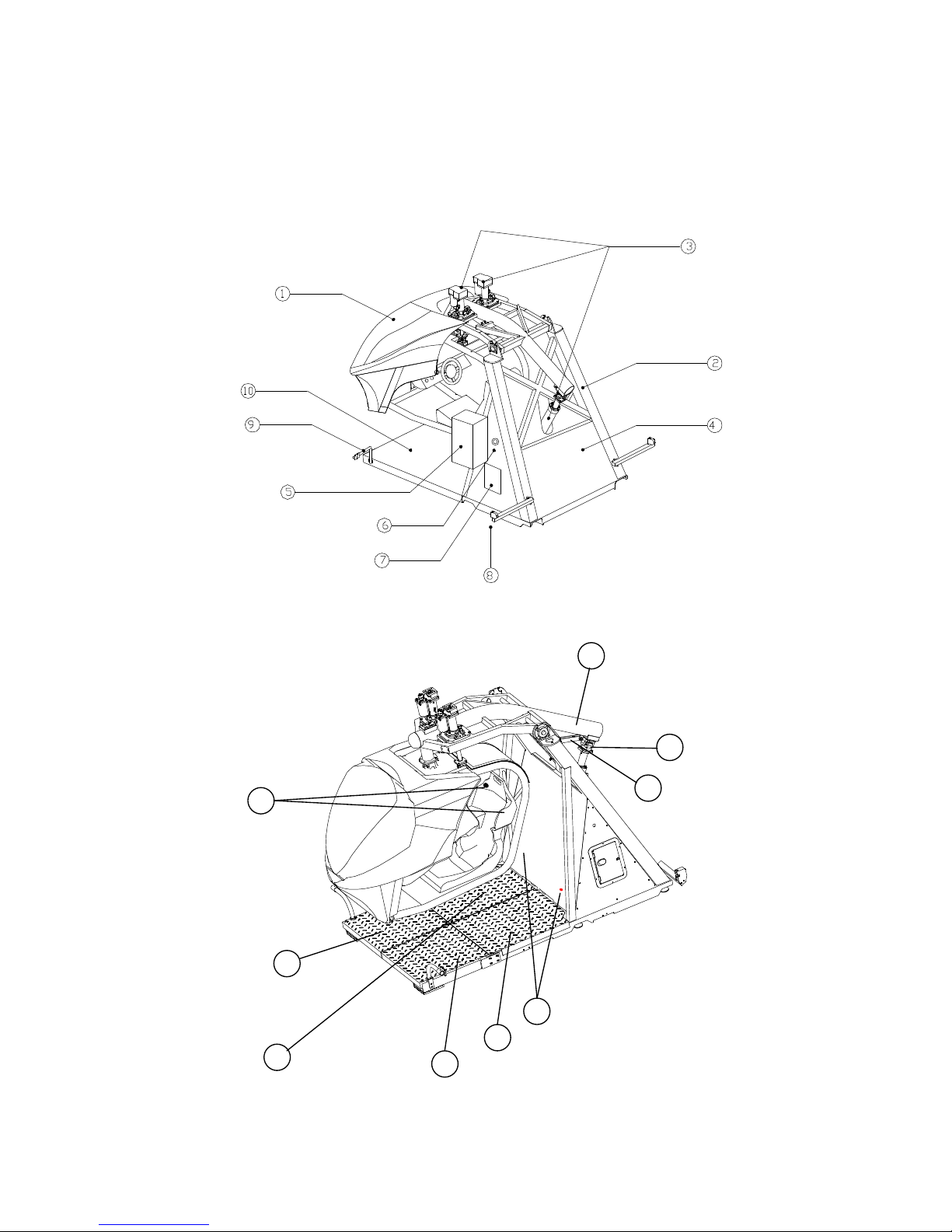
3. NAMES OF MAJOR PARTS
18
11
12
13
14
15
16
17
28
Page 17
No. Item Description
1 Cabin (Seat + Monitor) Carries the player and moves during operation.
2 Main Frame Holds the cabin, actuator system and
electronics.
3 Actuators Three electric linear actuators that move the
cabin in 3 DOF (degrees of freedom). The two
actuators on top of the cabin creates pitch and
roll motions. The actuator behind the cabin
creates heave motion.
4 Motion System Cabinet
Unit (MSCU)
Houses all the control electronics and electrical
components.
5 Coin Chute Tower Carries the coin chute mechanism.
6 Motion Stop Switch Pressing this button will stop the simulator
motion but game play will continue. Motion
resumes 3 seco
nds after the switch is released.
This button can be used in case of emergency
when motion must be stopped.
7 Operator Panel Houses indicators and switches to set and
control Cycraft. Refer to Chapter 2 for details.
22
19
20
27
21
23
25
24
26
29

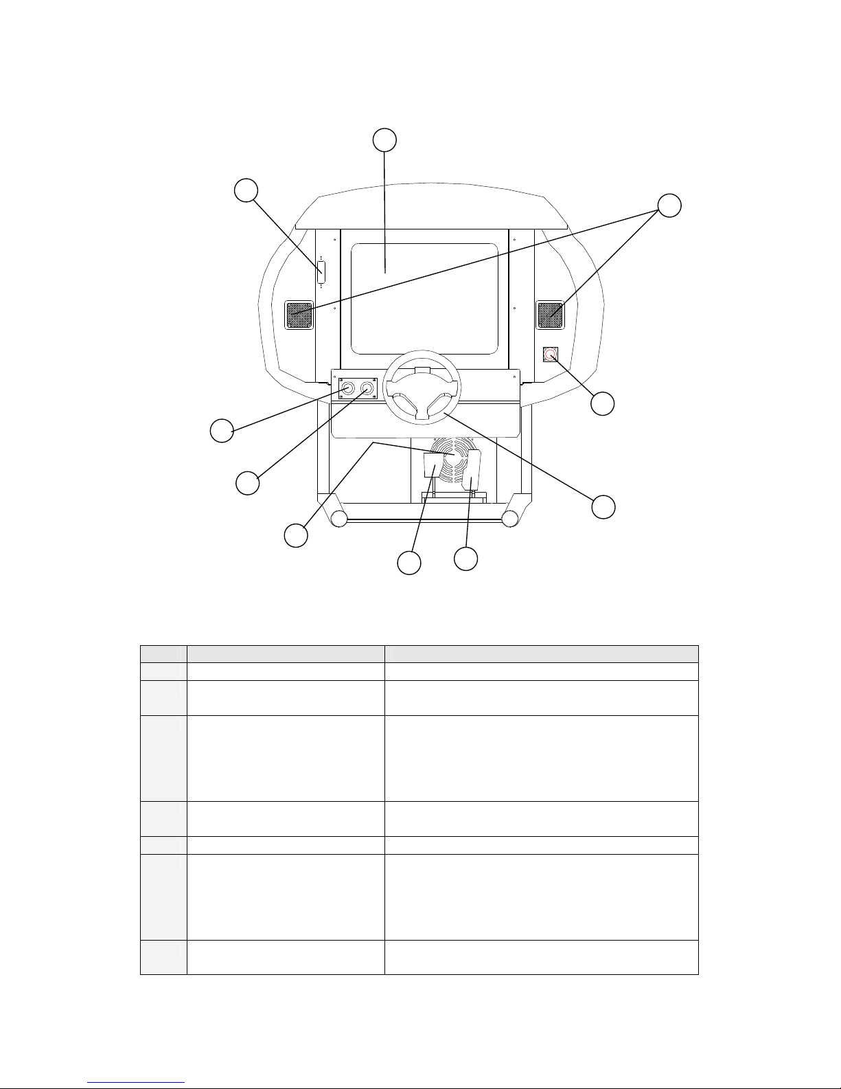
Page 18
8,9 Safety Photo Sensors &
Reflectors
There are 2 photo sensors on each side of the
outer frame. If any of the sensor lines are
obstructed, the simulator will stop in its current
orientation until 3 seconds after the removal of
the obstruction.
10 Safety Floor Sensor The metal floor plate underneath the cabin is a
pressure sensor that stops the simulators
motion when stepped on. The simulator will
begin to move again 3 seconds after the
removal of the pressure.
11~14Safety Floor Sensor Plates 11 = A type, 12 = B type, 13 = C type,
14 = D type
15 Floor Sensor Indicator
Lamp
Lamp (Green) goes off when the floor sensor is
activated.
16 Safety Link Safety link connected to the rocker arm.
17 Heave Actuator Joint
18 Rocker Arm Tilts up and down to create heave motion.
19 Start Button Begins the game after coin is inserted.
20 View Button Changes the driver’s view perspective during
play.
21 Game Stop Button Terminates the game and lowers the cabin to
the initial position.
22 Video Control Buttons Removing this cover exposes the control
buttons to adjust video screen parameters.
Refer to Chapter 2 for details.
23 Steering Wheel Produces steering input for the game.
24 Accelerator Pedal Produces accelerator input for the game.
25 Brake Pedal Produces braking input for the game.
26 Monitor Displays game graphics.
27 Front Speakers Produces audio effects.
28 Rear Speakers Produces audio effects.
29 Subwoofer Produces audio effects with low frequency

Page 19
4. TRANSPORTING AND MOVING
4.1 EQUIPMENT REQUIRED FOR UNLOADING AND TRANSPORT
No Equipment Description Qty Purpose
1 Fork Lift Capacity over 1500 kg
Boom attached fork
1 Lift and transport out of
packing crate.
2 Wood block 10 cm x 10 cm x 100 cm 4 Set under the base
frame so that fork can
be inserted and
removed easily.
3 Rear caster
(Supplied)
2 Used together with front
casters (already
installed) to roll the
machine to destination
location.
4 Socket wrench &
Extension bar
(Over 200 mm)
1 Attaching the rear
casters.
5 Wrench 1 Adjusting the level of
casters.
6 Philips type
screwdriver
1 Loosening and
securing
truss bolts
7 Bolt Hex head M12 x 35 L 6 Attaching the casters
4.2 UNLOADING AND OPENING THE CRATE
1) When unloading the crate from the container or truck, it is recommended to insert
the forklift from the heavier rear side of the crate.
2) The crate should not be opened from the front. Open the rear and/or one of the
sides when opening the crate.
Page 20
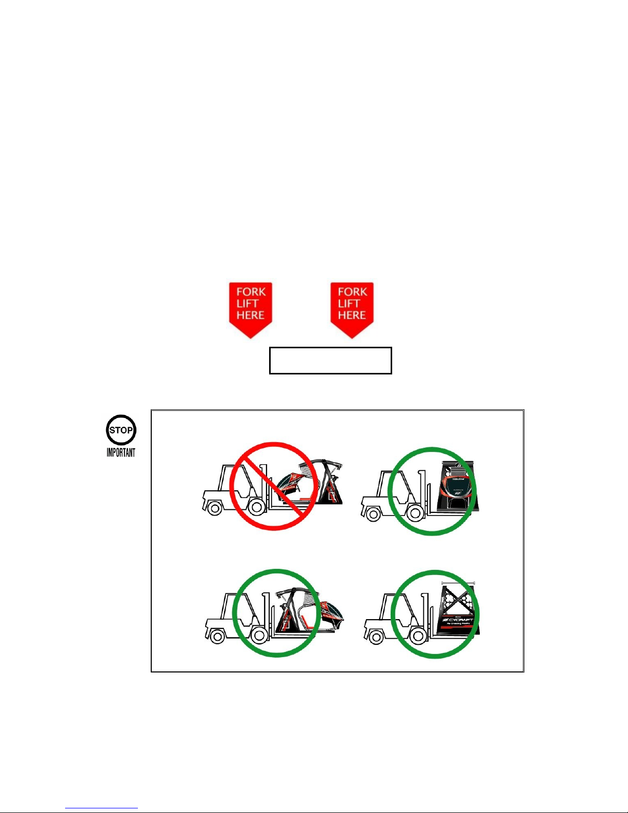
4.3 UNPACKING AND INSTALLING REAR CASTER WHEELS
1) After the crate is opened, unpack the separate accessories and components so
that the main simulator body is accessible.
2) Insert forklift from the rear of Cycraft or from the side. DO NOT INSERT FORKS
FROM THE FRONT SIDE. When inserting forks from the side, make sure the
forks are positioned to enter the cutoff sections in order to ensure Cycraft does not
tip over. Insert forks fully until the tips are visible on the other side.
DO NOT INSERT FORKS FROM THE FRONT SIDE
Fork Lift Insert Mark
Page 21
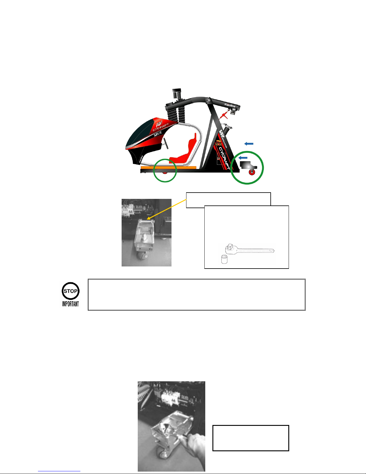
3) After CAREFULLY taking Cycraft out of the crate, install the rear two wheels by
first removing the MSCU cover as shown in the figure below. Note that the front
two wheels are already installed.
Be careful not to step on and damage the floor pressure sensor springs and
switches installed on the frame beneath the cabin
4) Adjust the heights of the wheels by rotating the nut on top of each wheel using
wrench until Cycraft is raised sufficiently for transport. Then, carefully roll Cycraft
to its destination location. After Cycraft is positioned in it’s installation location,
lower Cycraft by turning the wheel height adjustment nuts counterclockwise and
disassemble each of the wheel assembly.
To lift up the base frame,
turn the nut clockwise
3 x Hex head Bolt M12 x 35L
Socket wrench (19mm) &
Extension bar
(Over 200 mm)
Page 22
4.4 MOVING THE MACHINE
Only QUALIFIED SERVICE PERSONNEL should carry out this operation.
Cycraft simulator is a complex & delicate machine. Special care must always be taken
when handling Cycraft.
When moving Cycraft within a facility, it is recommended to utilize the casters provided
with the product. It is not necessary to disassemble the heave actuator and/or the safety
link. Only the fence and boarding step with coin chute need to be disassembled.
When Cycraft must be moved long distances by truck, it is recommended that the heave
actuator and safety link be disassembled such that the cabin is set securely on the base
of the outer frame. Trucking Cycraft without the heave actuator disassembled can cause
mechanical damage to the actuator due to shock and vibration during transport. Be sure
to lay the wooden plate between the cabin and the base frame as when Cycraft was
delivered. This plate protects the floor sensors and switches during transport.
l When moving the machine, be sure to remove the power cord and plug
from the power supply. Moving the machine with the power cord inserted can
cause the power cord to be damaged, resulting in a fire or electric shock when
installed in a new location.
l When moving the machine, with the heave actuator in the assembled
state, make sure that the machine is not exposed to high vibrations and shock.
Mechanical and structural damage can result.
Page 23
5. INSTALLATION INSTRUCTION
5.1 LOCATION REQUIREMENTS
5.1.1 ENVIRONMENT REQUIREMENTS
Cycraft is designed for indoor use and should never be installed outdoors.
Environment and facility requirements are as follows:
Installation location Indoor use only
Ambient temperature 5 to 40 C
Humidity 10 to 70 % (no condensing)
Min. Entrance
dimensions
1540 mm (W) x 2100 mm (H)
Min. Ceiling Height 2400 mm (H)
Min. Footprint
(incl. Fence)
4050 mm (L) x 2900 mm (W)
Min. Floor Loading 310 kg/m
2
Cleanliness Free of dust and debris
l Never install the game machine outdoors
Also avoid the following locations even though they are indoors.
l
Near a leaky roof, close to any kind of dripping water, or any place with high
humidity that can condense
l Close to an indoor pool or showers
l Exposed to direct sunlight
l Exposed to direct heat, such as close to a heater vent, or in a highly heated
room
l Close to flammable or volatile chemicals, or dangerous materials
l Avoid floors that slope(any slope more than 2 degrees)
l Avoid strong vibrations
l Avoid dusty locations
l Avoid any location that does not allow enough space around the machine
 Loading...