

Page 1
★★★
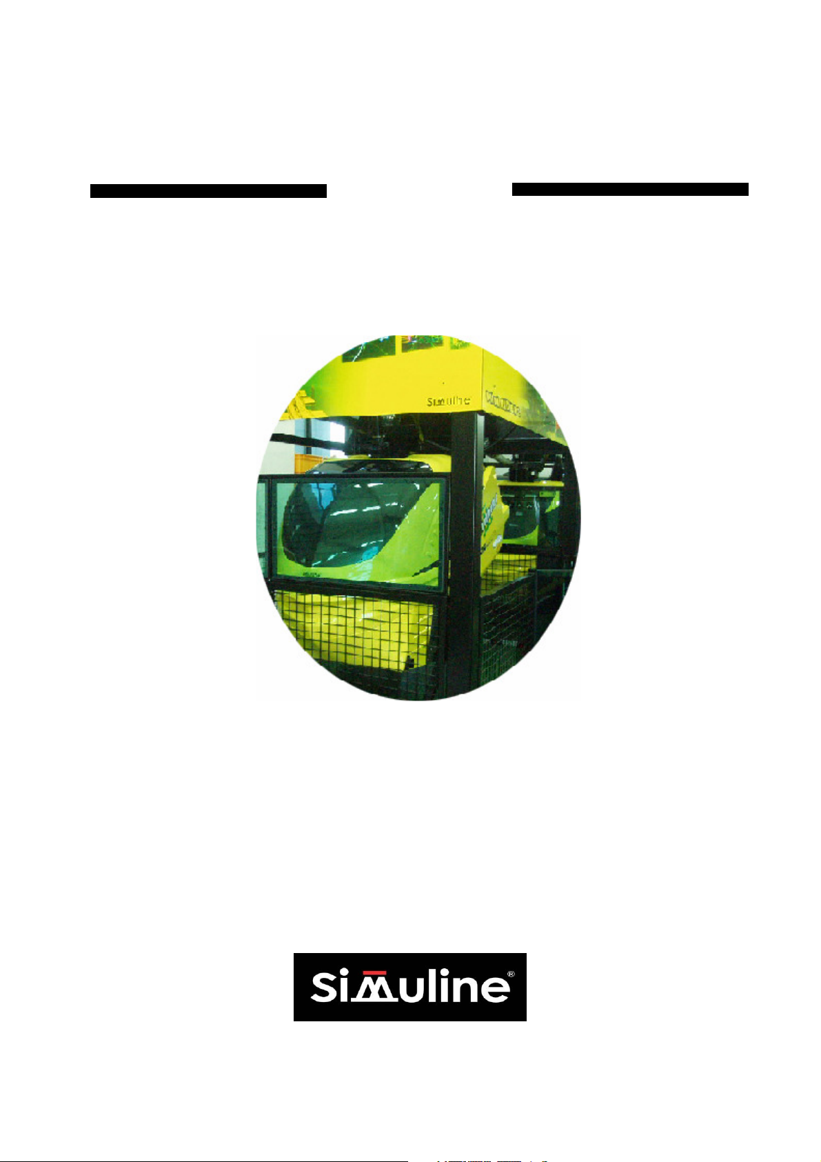
Mini Rider 2
User’s Manual
Page 2
BEFORE USING THE PRODUCT,
To maintain safety:
To ensure the safe operation of this product, be sure to read the following before usage.
The following instructions are intented for the users, operators and the personnel in charge of the
operation of the product. After carefully reading and sufficiently understanding the warning displays
and cautions, handle the product appropriately. Be sure to keep this manual close to the product or
in a convenient place for future reference.
Herein, explanations which requires special attention are enclosed with dual lines. Depending on
the potentially hazardous degrees, the terms of DANGER, WARNING, CAUTION, etc. are used.
Be sure to understand the contents of the displays before the text.
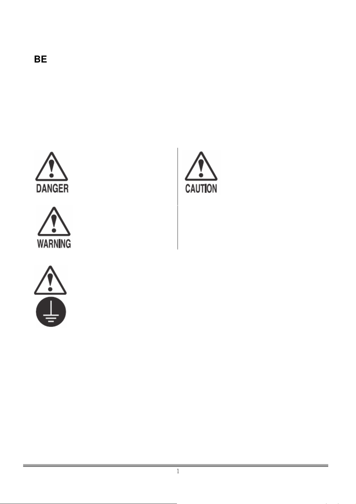
Indicates that mishandling the
product by disregarding this
pictograph will cause severe
injury or death.
Indicates that mishandling the
product by disregarding this
warning will cause a potentially
hazardous situation which can
result in death or serious injury.
BE SURE TO READ THE FOLLWING:
Indicates that mishandling the
product by disregarding this
caution will cause a slight
hazardous situation which can
result in personal injury and/or
material damage.
For safe useage of this product, the following pictographs are used:
Indicates “HANDLE WITH CARE.” In order to protect the human body and
equipment, this display is attached to places where the User Manual should be
referred to.
Indicates a “Protective Earth Terminal.” Before operating the equipment, be sure to
connect it to the Ground.
(The step may be omitted for products in which a power cord with earth is used.)
● Perform work in accordance with the instructions herein stated.
Instructions for work are explained by paying attention to the aspect of accident prevention.
Failing to perform work as per the instructions can cause accidents. In the case where only those
who have technical expertise should perform the work to avoid hazardous situation, the
instructions herein state that the serviceman should perform such work.
● Be sure to turn off power before working on the machine.
To prevent electric shock, be sure to turn off power before starting the work in which the worker
touches the interior of the product. If the work is to be performed in the power-on status, the
Instruction Manual herein always states to that effect.
●
Be sure to ground the Earth Terminal (this is not required in the case where a power cord with
earth is used).
This product equipped with the Earth Terminal. When installing the product, Connect the Earth
Terminal to the “accurately grounded indoor earth terminal” by using an earth wire. Unless the
product is grounded appropriately, the user can be subject to electric shock. After performing
repair, etc. for the Control equipment, ensure that the Earth Wire is firmly connected to the
Control equipment.
1
SIMULINE INC..
Page 3

●
Ensure that Power Supply used is equipped with an Earth Leakage Breaker.
This product does not incorporate the Earth Leakage Breaker. Using a power supply which is not
aquipped with the Earth Leakage Breaker can cause a fire when earth leakage occurs.
●
Be sure to use fuses which meet the specified rating. (Only for the machines which use
fuses)
Using fuses exceeding the specified rating can cause a fire and electric shock.
●
Specification changes (removal of equipment, conversion and additioin) not designated
by Simuline are not allowed.
The parts of the product include warning labels for safety, covers for personal protection, etc. It is
very hazardous to operate the product by removing parts and or modifying the circuits. Should
doors, lids and protective parts be damaged or lost, refrain from operating the product, and
contact where the product was purchased from or the office herein stated. Simuline shall not be
held responsible for any accidents, compensation for damage to a third party, resulting from the
specifications not designated by Simuline.
●
Ensure that the product meets the reqirements of appropriate Electrical Specification.
Before installing the product, check for Electrical Specifications. Simuline products have a
nameplate on which Electrical Specifications are described. Ensure that the product is
compatible with the power supply voltage and frequency requirements of the location. Using any
Electrical Specifications different from the designated Specifications can a fire and electric shock.
●
Install and operate the product in places where appropriate lighting is available, allowing
warning labels to be clearly read.
To ensure safety for the customers, labels and printed instructions describing potentially
hazardous situation are applied to places where accidents can be caused. Ensure that where
product is operated has sufficient lighting allowing the warnings to be red. If any label is peeled
off, apply it again immediately. Please place an order with where the product was purchased
from or the office herein stated.
●
When handling the Monitor, be very careful. (Applies only to the product w/monitor)
Some of the monitor(TV) parts are subject to high tension voltage. Even after running off power,
some portions are still subject to high tension sometimes. Monitor repair and replacement should
be performed only be those technical personnel who have knowledge of electricity and technical
expertise.
●
Be sure to adjust the monitor (projector) properly. (Applies only to the product w/monitor)
Do not operate the product leaving on-screen fleakering or blurring as it is. Using the product
with the monitor net properly adjusted may cause dizziness or a headache to an operator, a
palyer, ot the customers.
●
When transporting or reselling this product, be sure to attach this manual to the product.
In the case where commercialiiy available monitors and printers are used in this product, only the
contents relating to this product are explained herein. Some commercially available equipment
has functions and reactions not stated in this manual. Read this manual together with the specific
Instruction Manual of such equipment.
Description herein contained may be subject to improvement changes without notice.
・
The contents described herein are full prepared with due care. However, should any question
・
arise or errors can be found, please contact Simuline.
SIMULINE INC..
2
Page 4
INSPECTIONS IMMEDIATELY AFTER TRANSPORTING THE PRODUCT TO THE LOCATION.
Normally, at the time of shipment, Simuline products are in a status allowing for usage immediately
after transporting to the location. Nevertheless an irregular situation may occur during
transportation. Before turning on power, check the following points to ensure that the product has
been transported in a satisfactory status.
□
Are they any dented portions or defects(cuts, etc.) on the external surfaces of the cabinet?
□
Are Casters and Adjusters damaged?
□
Do the power supply voltage and frequency requirements meet with those of the location?
□
Are all wiring connectors correctly and securely connected? Unless connected in the
correct direction, connector connections can not be made accurately. Do not insert
connectors forcibly.
□
The fuses used meet specified rating? Is the Circuit Protector in an energized status?
□
Are all accessories available?
□
Can all Doors and Lids be opened with the Accessory keys? Can Doors and Lids firmly
closed?
SIMULINE INC..
3
Page 5

◈◈◈◈ TABLE OF CONTENTS ◈◈◈◈
■ BEFORE USING THE PRODUCT, BE SURE TO READ THE FOLLOWING
1. HANDLING CAUTION .................................................................................................................................5
2.INSTALLATION LOCATION CAUTION.........................................................................................................7
3.CAUTIONS:OPERATION .........................................................................................................................9
4. SPECIFICATION ..................................................................................................................................12
5. NAME OF THE PARTS...............................................................................................................................13
5-1. MAIN BODY ..........................................................................................................................13
5-2.SCU(SYSTEM CONSOLE UNIT) - FRONT.........................................................................................14
5-3. SCU(SYSTEM CONSOLE UNIT) – BACK …….................................................................................15
5-4. MCU(MOTION CONTROL UNIT).......................................................................................................15
5-5. O.P PANEL ……………......................................................................................................................17
6. ACCESSORY ..................................................................................................................................17
7. INSTALLING THE FENCE...................................................................................................................... …18
8. INSTALLATION ASSEMBLY.......................................................................................................................19
9. PRECAUTION OF MOVING SYSTEM AT THE LOCATION .................................................................53
10. DESCRIPTION OF SAFETY DEVICES .........................................................................................54
11. DESCRIPTION OF RIDES........................................................................................................................56
12. RIDE OPERATION INSTRUCTION..........................................................................................................57
13. SYSTEM ON ........................................................................................................................58
13-1. SYSTEM SETTINGS ....………………………………………………………………….……………..58
13-2. SYSTEM ON (POWER ON))............................................................................................................61
13-3. SYSTEM OFF (POWER OFF) ....................................................................................................61
13-4. EMERGENCY SITUATION .........................................................................................................62
14. MONITOR ..........................................................................................................................................63
14-1. MONIOTR HANDLING …….…………………………………………………………………………….63
14-2. MONIOTR SETTING ...………………………………………………………………………………….63
15. GREASE UP ........................................................................................................................................65
15-1. ACTUATOR GREASE UP .......................................................................................................66
15-2. UNIVERSAL JOINT …………………………….........................................................................66
15-3. MIDDLE JOINT ……………...........................................................................................................67
16. MAINTENANCE ……...........................................................................................................................68
16-1. PERIODIC INSPECTION................................................................................................................ 68
17. TROUBLE SHOOTING ...........................................................................................................................70
17-1. SYSTEM RECOVERY ………………………….……………………………………………………..70
17-2. TROUBLE SHOTTING ………………………………….……………………………………………….71
17-2. MCU ERROR……………………………………………………..…………………………………………71
SIMULINE INC..
4
Page 6
1. HANDLING CAUTIONS
When installing, maintaining or handling the product, the following cautions should be
observed in order to enjoy the game safely.
Failure to follow the warnings listed below and in other parts of this manual may cause
physical injuries or damage to the machine.
●
Before any installation or maintenance work, make sure to turn off the power.
Failure to do so may cause an electric shock or short-circuit. In case it is
necessary to keep the power on for a certain type of work, the manual will
explicitly state so.
●
Do not suddenly pull out or insert the power plug from/into an outlet. It may
cause an electric shock or short-circuit.
●
Do not attempt to touch any plug with wet hands. It may cause an accident
due to electric shock.
●
Power cables/cords or grounding wires should not be exposed such as on a
passage. The exposure may cause physical injuries, possibly resulting in
short-circuit or electric shock.
●
Do not place any article on power cables/cords nor damage them, for it may
cause a fire or electric shock.
●
Do not pull on the power cables/cords unnecessarily during or after
installation. Damaged cords may cause a fire or electric shock.
●
If any power cord is damaged, ask the manufacturer/supplier for a
replacement. Using a damaged power cord can result in a fire, electric shock
or electric leakage.
●
Make sure to earth the product. Incorrect grounding may also cause an
electric shock.
●
Use the rated fuse only. Using any fuse of incorrect rating may cause a fire or
electric shock.
●
Firmly connect IC boards and all connectors completely. Unstable connections
may cause an electric fire.
●
Do not make any unauthorized changes or modifications to the product.
・
Doing so may cause fire or an electric shock. In some cases it can hurt and
cause physical injury to the user/operator or bystander.
・
The manufacturer and/or seller will not be liable for any accidents that occur
on products that have undergone unauthorized modifications or changes
including but not limited to such modifications and changes performed by a
third party.
●
Make sure to always execute the routine maintenance procedures specified in
the manual.
●
When cleaning the surface of the cathode-ray tube monitor, use a soft and dry
cloth. Do not use chemicals such as thinner or benzene.
●
Static electricity in the human body can destroy electronic parts on IC boards.
Make sure to discharge any static electricity by measures such as setting
hands to a grounded metal plate before handling IC boards.
●
There are some components/parts, which are not specially designed and
manufactured for the product. Please understand that in case the
manufacturer of such components/parts discontinues production or changes
the specifications, it may not be possible to repair or replace such products
regardless of the warranted period.
5
SIMULINE INC..
Page 7
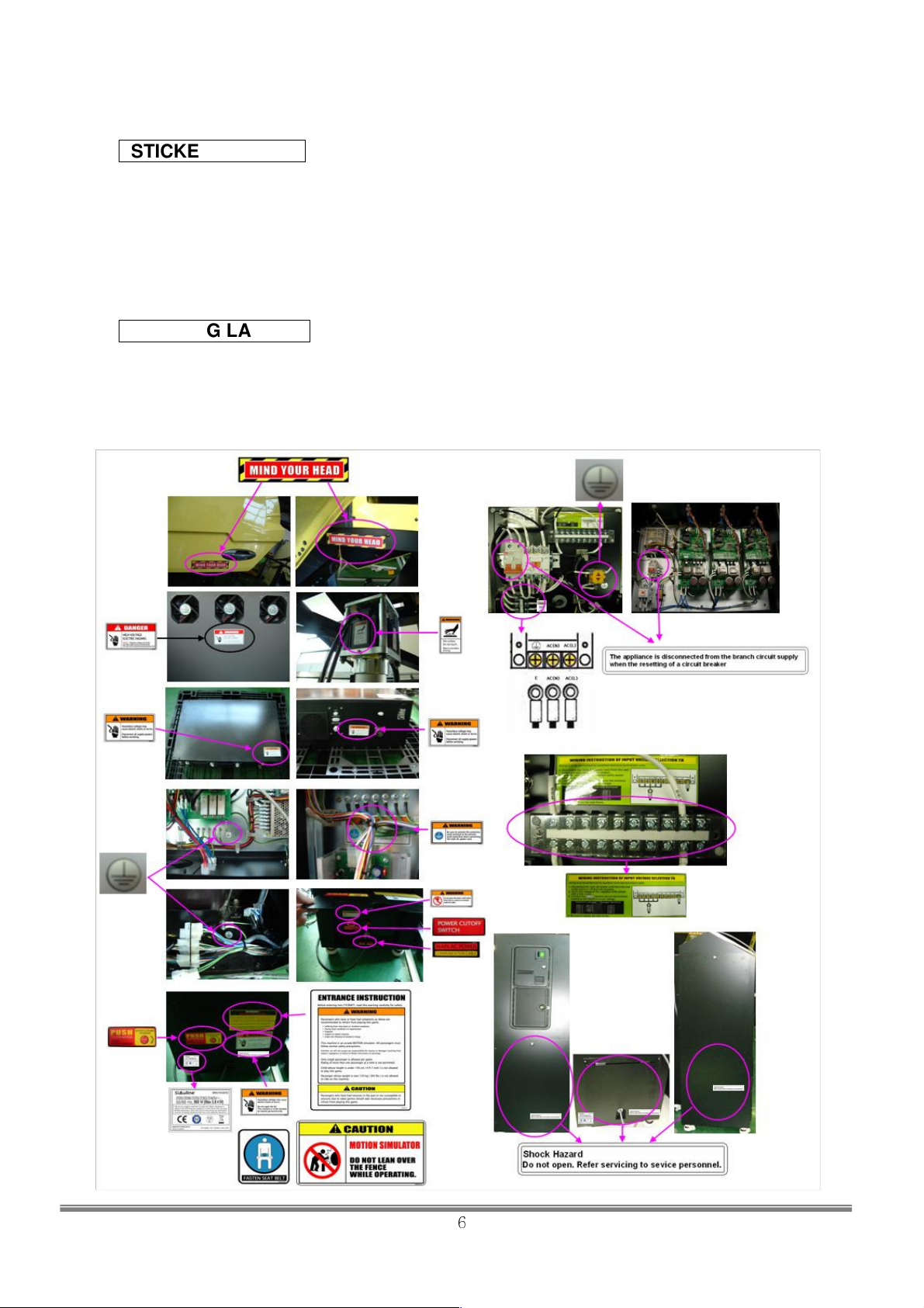
STICKER LABELS
The product contains sticker labels stating the product’s serial number (S/N) and electric
specifications. When you request repairs or have any inquiries, check your S/N first before you
contact us.
The S/N is the identification number of each product. Same models may have different parts
used depending on the production time. Also models may be improved after the manual is
issued. To deal with each case effectively, it is necessary that we are informed of the unique
S/N.
WARNING LABELS
Simuline’s product has stickers or labels to warn the users of any danger that might be presented upon the
users. This is to avoid any possible accidents while operating or maintenance work is done. There are
points in the Cabin that might cause electric shock just by touching the spot. When service work is required,
please set up a warning sign to warn the gallery. Specially, the work that is not noted in this manual should
be carried out by a qualified electrician or an engineer. Anyone who does not follow the warning sings may
not be allowed to approach the machine.
SIMULINE INC..
6
Page 8

2. INSTALLATION LOCATION CAUTIONS
Electric Power Consumption
The product is intended for indoor use. Therefore, do not install it outdoors.
Even when installed indoors, the following locations should be avoided. They
may cause a fire, electric shock or breakdown.
・
Places with raindrops or water leakage, or places with high humidity such as
RESTRICTIONS FOR USE
indoor swimming pools or showers.
・
Places that have a high temperature such as places with direct sunlight or
close to heating sources.
・
Places near flammable gas, explosive chemical or dangerous substances.
・
Places that are dusty
・
Places with an incline.
・
Places with intense vibration
・
Places near anti-disaster facilities such as emergency exit or fire extinguisher
・
Any other place outside of the allowable temperature range (ambient temp.) of
5
℃
~30℃.
●
Check your electric specifications.
Check whether the product conforms to the voltage, current and frequency
provided at the installation location. For the electric specifications, see the
plate (label) attached on the product.
If electric source outside of the specification is used, it can cause a fire or
electric shock.
●
Inside the installation location, a breaker and an earth connection for the
product are required. An independent electric source for the product should
be provided to prevent fire or electric shock.
●
Make sure to use the power cable in accordance with power consumption as
described below. Using power cable of other electric specifications can cause
a fire or electric shock.
●
Make sure to use the power with independent circuit breaker. Using any
power source without circuit breaker can cause a fire.
●
Do not have many electrical cords connected to a single socket. Overload
can cause the generation of heat or a fire.
●
If an extension cord is used, it should be rated the max current or higher as
described below. Using a cord of different specifications can cause a fire or
electric shock.
MAX. 15A (AC220V 50/60Hz)
MAX. 15A (AC220V 50/60Hz)
MAX. 15A (AC220V 50/60Hz)MAX. 15A (AC220V 50/60Hz)
SIMULINE INC..
7
Page 9
OPERATIONAL FLOOR AREA
●
For proper operation, a floor area of
required. In case of interference with the motion of the cabin or if the player
falls off the cabin, serious injury can occur. Therefore, the specified area
should be secured at all times.
●
Ventilation area specified in this manual should be secured. In addition,
ventilation vents and ports should not be blocked by obstacles. Blocked
ventilation may cause the generation of heat or a fire.
●
In case any accident occurs while the product is operated on a floor area less
than specified, the manufacturer will not be responsible for any liability or
reparations.
●
In case the product cannot fit through the entrance of a location, do not
disassemble without proper preparations. Disassemble only the parts as
specified in this manual. Do not attempt a disassembly procedure not
described in this manual. Special tools and adjustment procedures are
required to disassemble/assemble much of the mechanical parts of the
product. Improper disassemble/assemble can lead to accident during
disassembly/assembly such as electrical shock and human injury. If the
product does not fit through the entrance even after the disassembly
specified in this manual, contact the manufacturer/supplier or the contact
provided in this manual.
●
Do not tilt the product or subassemblies in an attempt to pass through small
entrances. This can cause accidents during the transportation. In addition, it
can cause damage or deformation to parts and result in accidents during
operation.
3700mm X 2500mm
meters or more is
To fit the product in a location, the size of the entrance should be, at least,
1300mm
wide and
1550mm
high.
SIMULINE INC..
8
Page 10
3. CAUTIONS: OPERATION
For safe operation, please obey the following warnings and instructions.
CAUTIONS: OPERATION
Check the following cautions before working hours to prevent accidents.
● To prevent any player or other customers from headache or dizziness, the
product should be installed in a well-lighted place so that warning signs can be
clearly read. Improper lighting can cause unexpected problems such as contact
between customers, collision, and other undesirable situations.
● Adjust the monitor appropriately.
If monitor blinking is detected, do not leave it un-adjusted. Inappropriate
monitor adjustment can cause dizziness or headache to players and other
customers.
● Prepare a resting facility for players to take a rest in case he (she) needs to rest
due to conditions such as motion sickness.
● Check whether the level adjusters are securely set to the ground. If not, the
product is not properly set and can result in an accident.
● Do not place any heavy article on the product. It can cause an accident if
dropped and can also damage components.
● Do not climb on the product. Accident can be caused from falling. If it is
necessary to check the top of the product, use a stepladder.
● Check whether any doors or cover sections are damaged or separated. It can
cause electric shock.
● Do not place the following articles on or inside the control panel, on top of the
seat, on the top of the product or in the vicinity of the product. Doing so may
cause short-circuit, electric shock or damage parts.
Vase, pot, cup, water bucket, cosmetics and containers containing chemicals
or water.
● Check the surroundings before turning the product on. Once it is turned on, the
product is automatically initialized. If anyone is too close to the product during
initialization, collision with the moving cabin can occur.
● For safe operation, make sure to execute a trial operation after power on. Since
the cabin moves, the product is equipped with safety devices. Please check
whether these safety devices work normally as follows.
▪ Does the seat belt secure the player properly?
▪ Is the seat belt free of damages or excessive wear?
▪ Does the motion stop automatically when the seat belt is loosened.
▪ Is the seat attached securely without looseness?
▪ Does the product stop when the GAME STOP button is pressed?
▪ Does the product stop when the front/side beam sensors are tripped?
▪ Does the product stop when the floor beam sensor is tripped?
● In addition to checking the safety devices, make sure that the product moves
normally. Any abnormal motion can cause accidents. Do not operate the
product unless all abnormalities are resolved.
▪ Does the product move in sync with steering wheel operation?
▪ Does the product move smoothly?
▪ Does the product move securely without looseness?
▪ Is there any abnormal noise or sound when moving?
▪ Is there any abnormal vibration when moving?
▪ Does the product return to the initial standby position and stop when the
game is completed?
SIMULINE INC..
9
Page 11
● If any abnormality in the motion system is suspected, immediately stop all
operations, turn off the product and disconnect the power cord. Then, call your
local dealer or the contact point listed in this manual. If the product is operated
abnormally, serious accidents such as electric shock, fire, collision, etc. can
occur.
● For the proper maintenance of the motion system, please contact the contact
point listed in this manual. If improperly trained personnel perform the
maintenance work, accidents can occur during the maintenance work and can
cause accidents to customers and players.
● To help prevent accidents, make sure to install the auxiliary fence and ensure
that the product operates properly within the fenced area. Failure to secure
sufficient floor space with the fence can result in accidents due to collision and
contact between players and objects.
● Make sure there is no damage to surfaces which the player touches during
play. Such damaged surfaces can cause cuts and injury.
CAUTIONS : OPERATION (TO THE PLAYER)
To prevent accidents and/or unnecessary problems, alert players or customers to be aware of
the following.
● Anyone who falls into one or more of the following should be prevented from
playing the game. It may cause an accident or injuries.
▪ Persons who need assistance when walking, and persons with high blood
pressure or heart disease.
▪ Persons who have experienced spasms/convulsions or unconsciousness’ after
playing a TV video or similar game.
▪ Persons who have neck or backbone trouble.
▪ Pregnant women or persons who are intoxicated..
▪ Persons susceptible to vomiting from amusement rides.
▪ Persons that do not follow warning signs.
● Even persons who have never experienced discomfort due to phobic stimulation
may experience dizziness, nausea, and/or headaches from playing this game.
● If discomfort becomes severe, advice a player to consult a doctor.
● Do not place any heavy articles or beverages on top of the product. Accidents from
the falling articles and accidents due to electric shock can occur.
● Do not insert your finger or any foreign substances into any open parts or doors of
the product. It may cause electric shock or short-circuit.
● Do not lean on or climb on the product. It may cause accidents from falling and
turnover of the product.
● Do not pull out the power plug recklessly. It may cause short-circuit or electric
shock.
SIMULINE INC..
10
Page 12
● For safety reasons, persons shorter than 140cm (55.11 in.) are not permitted to
play this game. Please explain that such persons cannot be safely secured with
the provided safety belt.
● Persons whose weight is over 120kg (265lbs.) are not permitted to board.
● Playing without the seat belt fastened can cause an accident by falling from the
cabin. Make sure the player secures their body with the seat belt before playing
the game
●. No one should hang on the cabin behind the seat. This can cause serious injury
due to falling, jamming of body parts between structures, and turnover of the
product. If anyone is found hanging on to the cabin, make sure the person gets
off.
SIMULINE INC..
11
Page 13
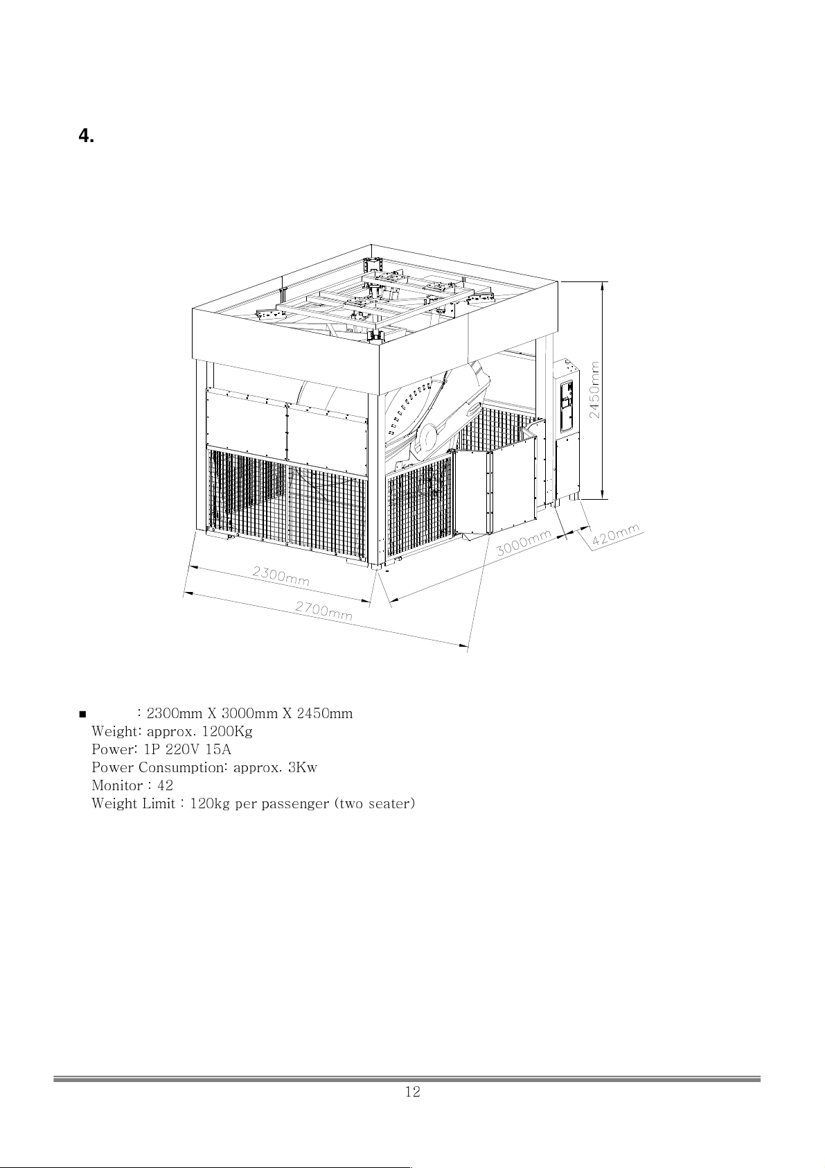
4. Specification
■ Volume
■
Weight: approx. 1200Kg
■
Power: 1P 220V 15A
■
Power Consumption: approx. 3Kw
■
Monitor : 42”
■
Weight Limit : 120kg per passenger (two seater)
: 2300mm X 3000mm X 2450mm
SIMULINE INC..
12
Page 14
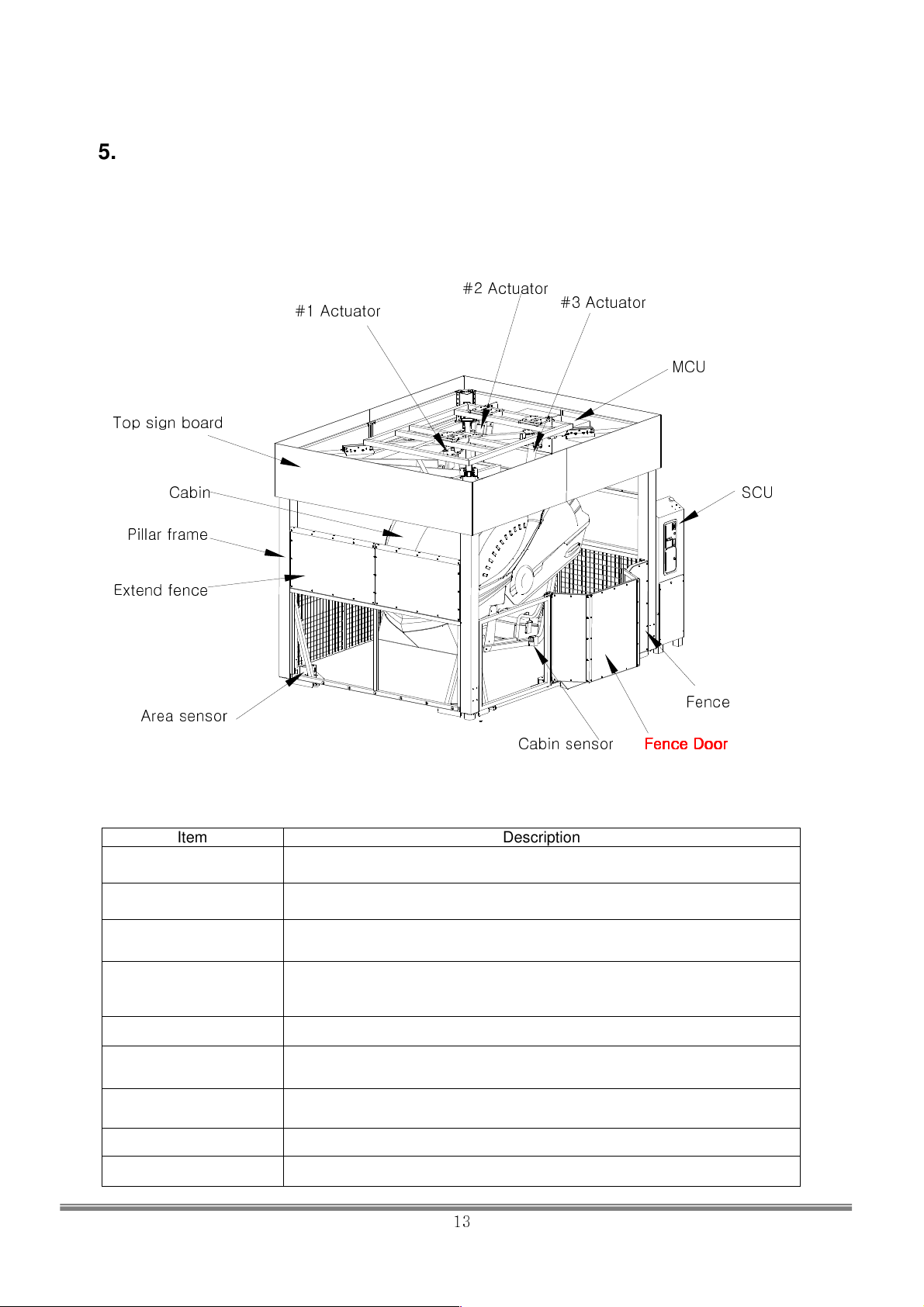
5. Name of the parts
5-1. Main Body
Top sign board
Actuator
#1
#2 Actuator
#3 Actuator
MCU
Cabin
Pillar frame
Extend fence
Area sensor
Item Description
Motion Actuator
Mechanism
MCU (Motor Controller
Unit)
SCU (System Console
Unit)
Fence
Cabin sensor
Motion Driving Actuators and anti-twist structure made of links.
Controllers that drive the actuators. 3 units.
Contains system control, movie control unit and coin tower.
Fence Door
Fence Door
Fence DoorFence Door
SCU
Area Sensor
Fence Door Door for riders. (one side)
Cabin Sensor
Pillar Frame Structure that hold up the motion system and MCU.
Cabin Semi-enclosed cabin with seats for 2.
Top Sign Board Sign Board
Area sensors that detect any obstacles. When triggered, motion stops
unitl the obstacles are removed and resumes after 3 sec.
Cabin sensors that detect any obstacles. When triggered, motion stops
unitl the obstacles are removed and resumes after 3 sec
SIMULINE INC..
13
Page 15
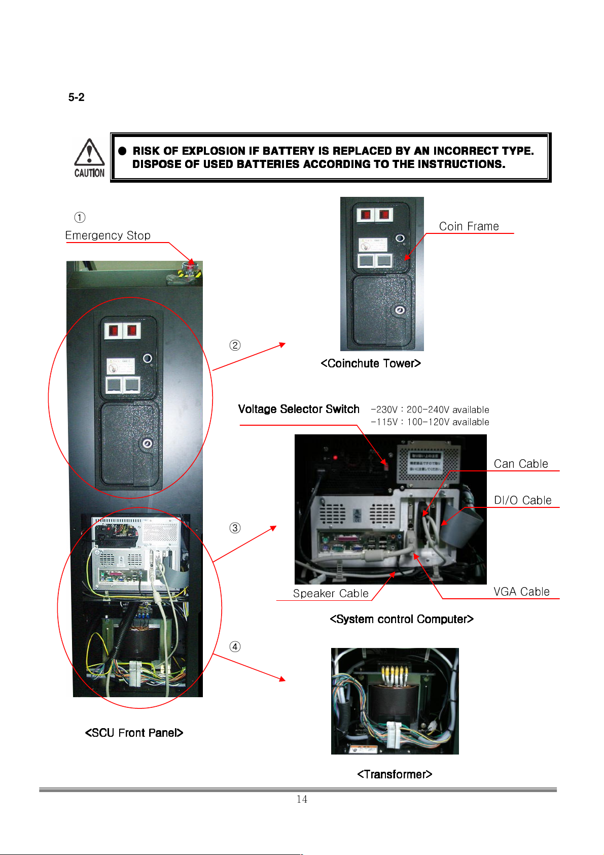
5-2. SCU(System Console Unit) - Front
●
RISK
RISK OF EXPLOSION IF BATTERY IS REPLACED BY AN INCORRECT TYPE.
OF EXPLOSION IF BATTERY IS REPLACED BY AN INCORRECT TYPE.
RISKRISK
OF EXPLOSION IF BATTERY IS REPLACED BY AN INCORRECT TYPE. OF EXPLOSION IF BATTERY IS REPLACED BY AN INCORRECT TYPE.
DISPOSE OF USED BATTERIES ACCORDING TO THE INSTRUCTIONS.
DISPOSE OF USED BATTERIES ACCORDING TO THE INSTRUCTIONS.
DISPOSE OF USED BATTERIES ACCORDING TO THE INSTRUCTIONS.DISPOSE OF USED BATTERIES ACCORDING TO THE INSTRUCTIONS.
①
Emergency Stop
①
①
<SCU Front Panel>
<SCU Front Panel>
<SCU Front Panel> <SCU Front Panel>
②
<Coinchute Tower>
<Coinchute Tower>
<Coinchute Tower><Coinchute Tower>
Voltage Selector Switch
Voltage Selector Switch
Voltage Selector SwitchVoltage Selector Switch
-115V : 100-120V available
-230V : 200-240V available
③
Speaker Cable
<System control Computer>
<System control Computer>
<System control Computer><System control Computer>
④
<Transformer>
<Transformer>
<Transformer><Transformer>
④
Coin Frame
Can Cable
DI/O Cable
VGA Cable
SIMULINE INC..
14
Page 16
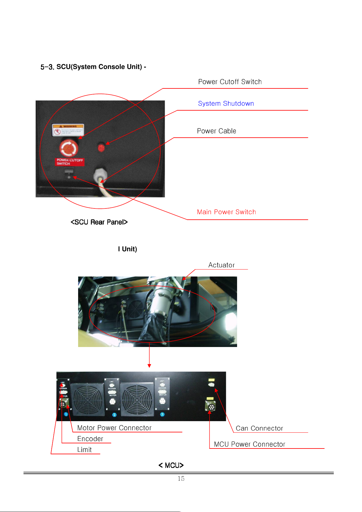
5
SCU(System Console Unit) - Back
-3.
3.
555---
3. 3.
<SCU Rear Panel>
<SCU Rear Panel>
<SCU Rear Panel><SCU Rear Panel>
5-4. MCU(Motion Control Unit)
Motor Power Connector
Encoder
Limit
< MCU>>>>
< MCU
< MCU< MCU
⑤
Power Cutoff Switch
⑥
System Shutdown
⑦
Power Cable
⑧
Main Power Switch
Actuator
MCU Power Connector
⑤
Can Connector
SIMULINE INC..
15
Page 17

Item Description
Stops the cabin from moving. When released by turning the
1 Emergency Stop
2 Coinchute Tower
nob, game will be stopped and the cabin will move to the
initial position.
Coinchute Tower is designed to suit various types of coin
frame. For Japan, Asahi Seiko, and others are recommended
to use HAPPS products (Model NO. 42-3272-00.)
System Control Computer
3
4 Transformer
5 Power Cutoff Switch
6 System OFF
7 Power Cable Main Power Cable
8 Main Power Switch
Computer that controls the hardware and everything that operates
the machine.
Adjusts the voltage according to the country.
Only used to stop the machine even when the Emergency stop
button is pressed and doesn’t work.
When pressed, the power to the MCU and the Actuators. Cabin
stops at the last position and comes down to power off position
slowly. Do not force the cabin to come down faster.
“Warning” DO NOT PRESS THIS BUTTON EXCEPT FOR
EMERGENCY.
When pressed for 2 sec., cabin will come down to the initial
position and the power to MCU is cut off. System control PC will
shut down.
When pushed to ON position, system starts up. Initialization will
be processed. Cabin moves up to boarding position.
SIMULINE INC..
16
Page 18

5-5. O.P Panel
O.P Panel is located inside the Coinchute Tower of the SCU.
⑨
⑩
⑪
Item Description
SVC
9
(Service)
TEST Button
10
F-VOL
11
R-VOL
6. Accessory
Inputs the credit.
Used to update the operating software or to do service works. Also used to
diagnose conditions of the System Control Computer. To use this
mode, press and hold the button while turning on the system. This
button will not work while in operation.
“CAUTION” Only the certified service man shall use this mode.
Front speaker volume
Rear speaker volume
Part Number
SCU Key 2
Coinchute Tower Key 2
Manual 1
SIMULINE INC..
17
Page 19

7. Installing the Fence
●
Mini-Rider is a motion simulator. Rectangular fence must be installed before
operating.
■ Install the door at the entrance.
Size 2300mm x 3000mm x 1000mm
Material, Installation
Ex.
Fence is equipped with strong PC(polycarbonate) screen to keep the
gallery away from the moving cabin. Fence must be securely
fastened to the main frame with supplied bolts.
SIMULINE INC..
18
Page 20
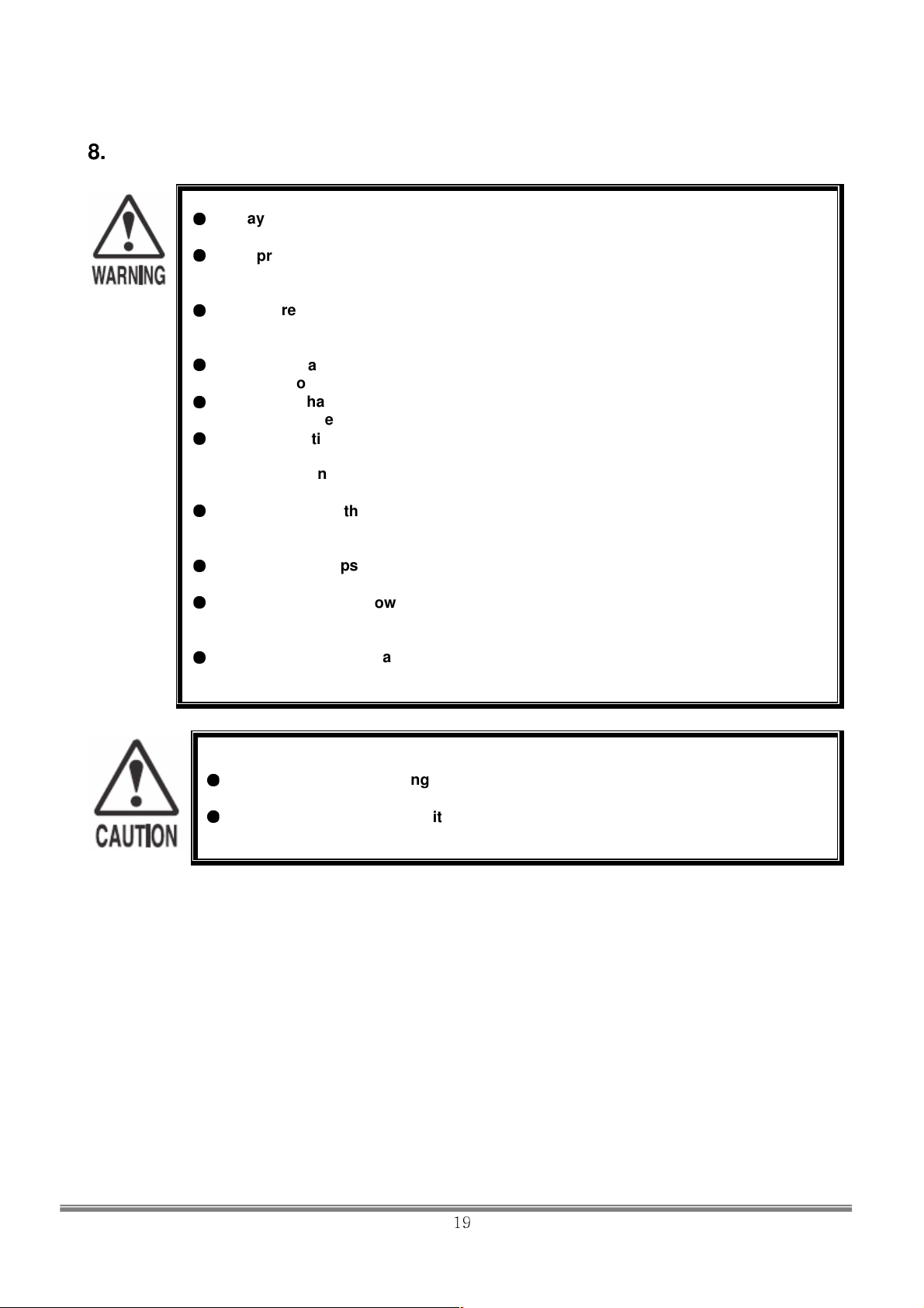
8. Installation Assembly
Always follow the instructions in this manual. Not following this manual fully may
This product has a complex structures and equipments. Misses in assembly may
shock or damages to the machine and cannot guarantee normal
Make sure there are a crew of 4 or more is available for installation. This machine
cannot be assembled by one technician. If the installation is carried out by one
Make sure all of the connectors are connected to the proper positions firmly.
d during installation.
This installation must be carried out by the manager of the store or the service
ur.
Also, if the installation instructions in this manual is not followed fully, severe
Make sure that the required space is available for the installation. The space
on is noted in this manual. Insufficient installation space
Slanted floor, gaps, elevation difference must be avoided for installation. Cabin or
wer cable, earth line and etc where people might walk over
them. Damaged cables may cause electric shocks or short circuits. Use cable
●
cause electric shocks or other accidents.
●
cause electric
operation in those cases.
●
person, accidents or damages to the machine may occur.
●
Insecure connections may cause malfunctions or electric shocks.
●
Make sure that none of the cables and harnesses are damage
Damaged cables and harnesses can cause electric shocks or short circuit.
●
manager. If an unqualified personnel installs this machine, accidents may occ
accidents may occur to both of the passengers and workers.
●
required for the installati
may cause accidents during installation.
●
frames may tip over and cause sever accidents.
●
Do not expose the po
floor molds to protect them.
●
Do not cover the vent at SCU. It may cause overheating and possibly fire.
Make sure there are at least 2m of room in front of the door for traffic.
●
Use caution while working with molded parts. Too much pressure can damage
the parts. This may cause injuries.
●
Be careful when working with doors to avoid head injuries.
SIMULINE INC..
19
Page 21
Follow the below order when installing the product.
(0) Unpacking and unloading the product
(1) Line up all the parts
(2) Settle the Pillar frame in position
(3) Assemble the Pillar frame and upper support frame
(4) Assemble the Pillar frame and lower support frame
(5) Assemble the Pillar frame and X-frame(=actuator support frame)
(6) Assemble the Pillar frame and Arm frame
(7) Connect Actuators to the X-frame
(8) Assemble the Cabin
(9) Assemble the MCU support bracket
(10) Assemble the Side Fence
(11) Assemble the Door Fence and Door box
(12) Assemble the Area Sensor and Sensor Setting
(13) Fasten SCU
(14) Assemble Top Sign Board
(15) Assemble the ramp
Install the Casters
(16) Connect Power
※
Coin Frame Installation - Option
※
※※
※※※※
– Option
SIMULINE INC..
20
Page 22
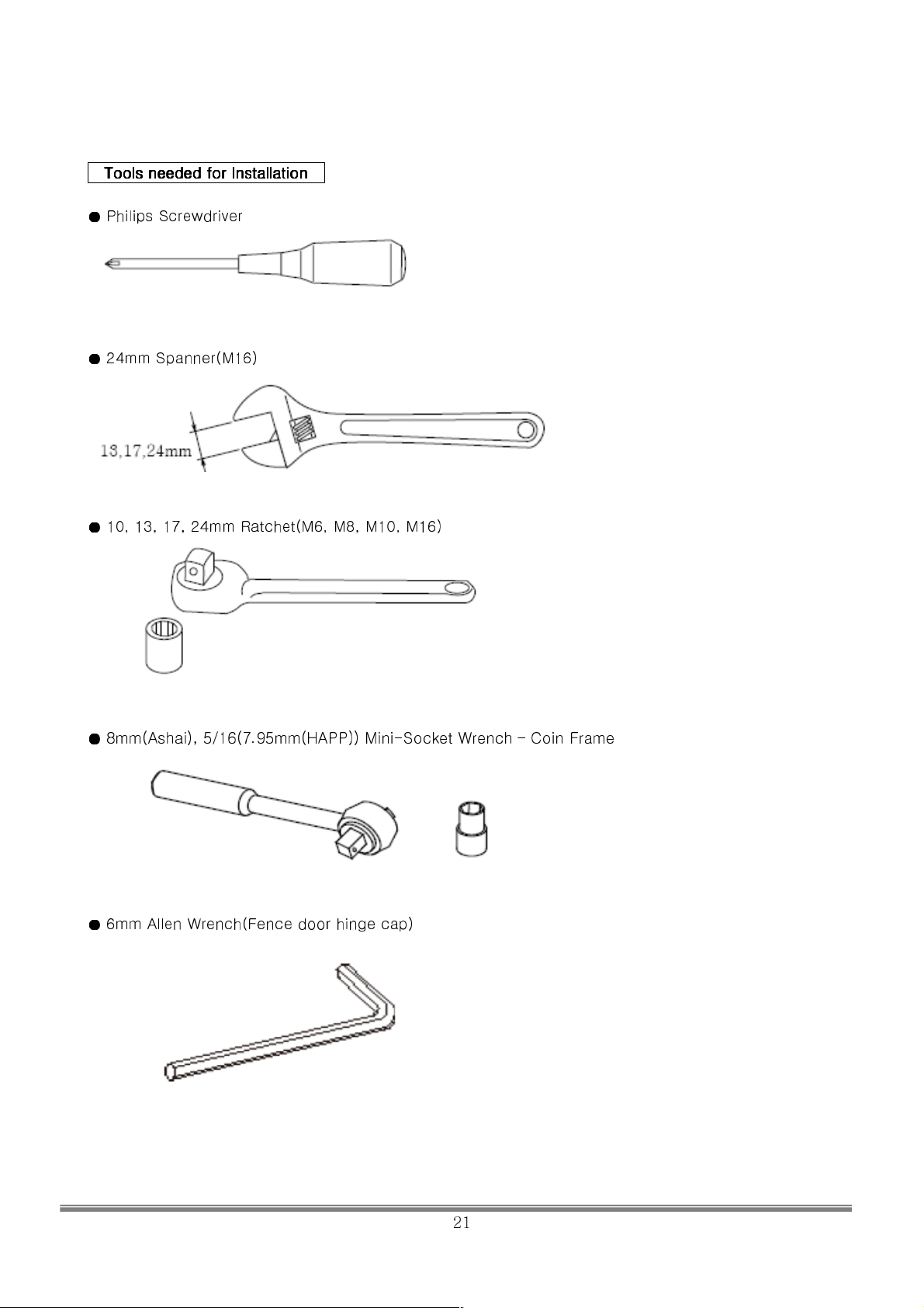
Tools
Tools needed
ToolsTools
needed for
neededneeded
for Installation
Installation
forfor
InstallationInstallation
●
Philips Screwdriver
●●●
●●●●
24mm Spanner(M16)
●●●●
10, 13, 17, 24mm Ratchet(M6, M8, M10, M16)
●●●●
8mm(Ashai), 5/16(7.95mm(HAPP)) Mini-Socket Wrench – Coin Frame
●●●●
6mm Allen Wrench(Fence door hinge cap)
SIMULINE INC..
21
Page 23
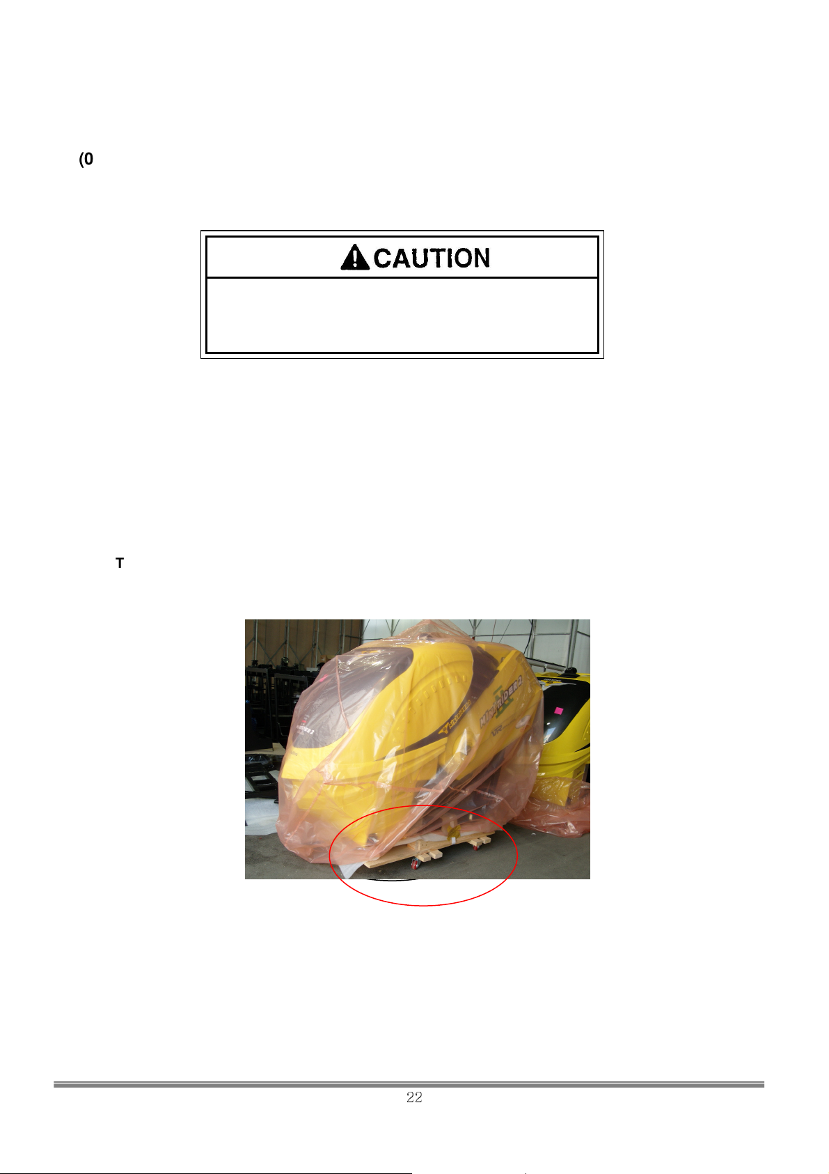
the steel
frames away from the cabin before moving the machine or
(0) Unpacking and unloading the product
Unpack and unload the product using a forklift
Be sure to remove the wood fixation and separate
lifting the cabin with a forklift.
Unpack the wooden crate by first disassembling the top panel of the crate and then the side walls. The
crate consists of the following parts;
i. Main cabin and all frame assembly
ii. Actuator units
iii. Fences
iv. System Control Unit (SCU)
v. MCU(Motor Control Unit)
vi. Top sign board
vii. Installation box
CAUTION ! LIFTING THE CABIN
Please make sure to lift the cabin slowly underneath the bottom wooden cart!!
Do not remove the wooden cart!! The cabin on the wooden cart is adjusted in height so that the
three actuators are bolted to the cabin
SIMULINE INC..
22
Page 24
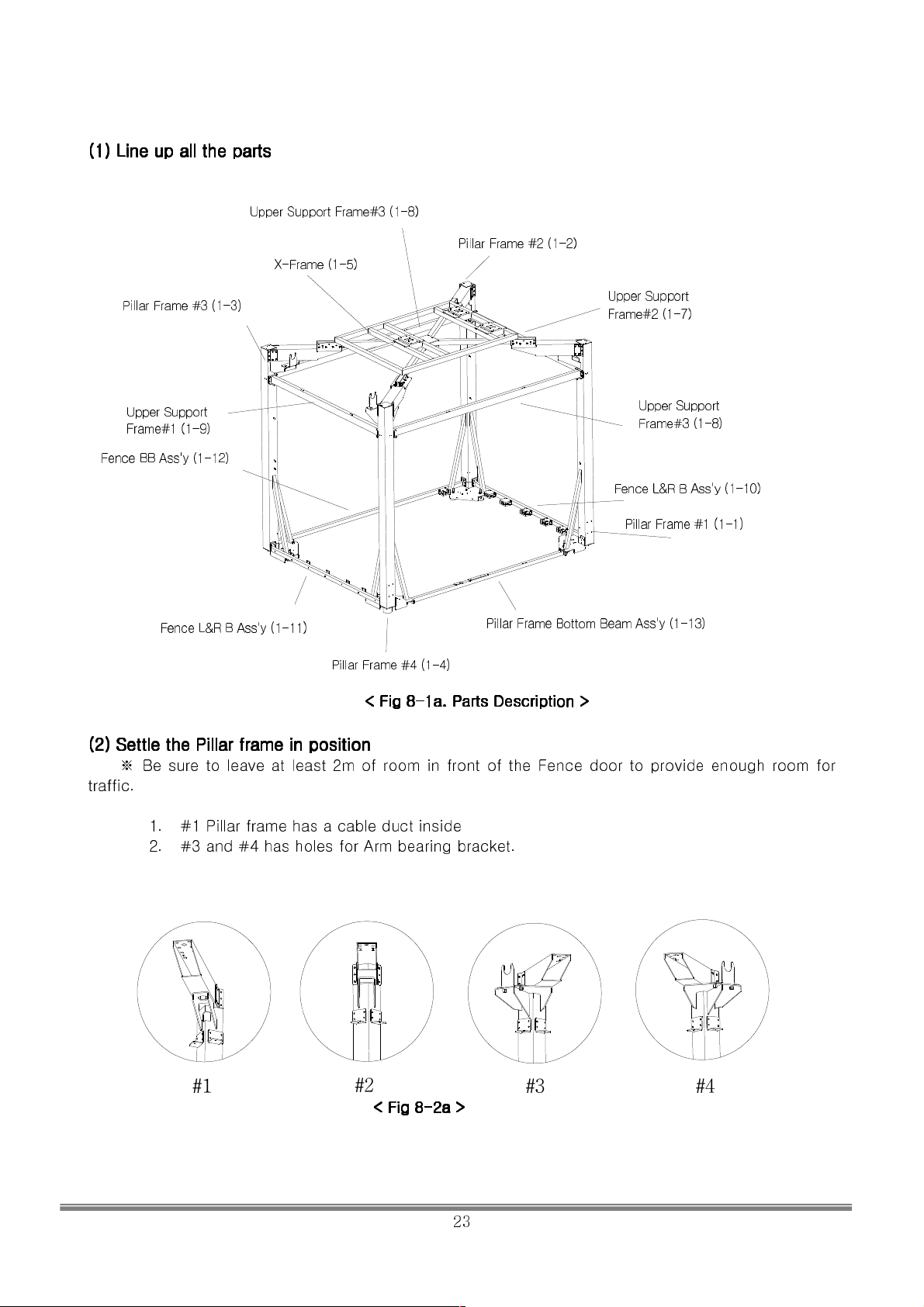
(1) Line up all the parts
(1) Line up all the parts
(1) Line up all the parts(1) Line up all the parts
Upper Support Frame#3 (1-8)
Pillar Frame #2 (1-2)
X-Frame (1-5)
Pillar Frame #3 (1-3)
Upper Support
Frame#1 (1-9)
Fence BB Ass'y (1-12)
Fence L&R B Ass'y (1-11)
Pillar Frame #4 (1-4)
(2) Settle the Pillar frame in position
(2) Settle the Pillar frame in position
(2) Settle the Pillar frame in position(2) Settle the Pillar frame in position
Be sure to leave at least 2m of room in front of the Fence door to provide enough room for
※
traffic.
1. #1 Pillar frame has a cable duct inside
2. #3 and #4 has holes for Arm bearing bracket.
< Fig 8
< Fig 8----1a. Parts
< Fig 8< Fig 8
1a. Parts Description
1a. Parts 1a. Parts
Upper Support
Frame#2 (1-7)
Upper Support
Frame#3 (1-8)
Fence L&R B Ass'y (1-10)
Pillar Frame #1 (1-1)
Pillar Frame Bottom Beam Ass'y (1-13)
Description >
DescriptionDescription
>
> >
#1
#2
< Fig 8
< Fig 8----2a >
< Fig 8< Fig 8
2a >
2a >2a >
#3
#4
SIMULINE INC..
23
Page 25
(3) Assemble the
(3) Assemble the Pillar frame to support frame
(3) Assemble the (3) Assemble the
Pillar frame to support frame
Pillar frame to support framePillar frame to support frame
●●●●
Do not tighten the bolts all the way (Tighten them temporarily)
Do not tighten the bolts all the way (Tighten them temporarily)
Do not tighten the bolts all the way (Tighten them temporarily)Do not tighten the bolts all the way (Tighten them temporarily)
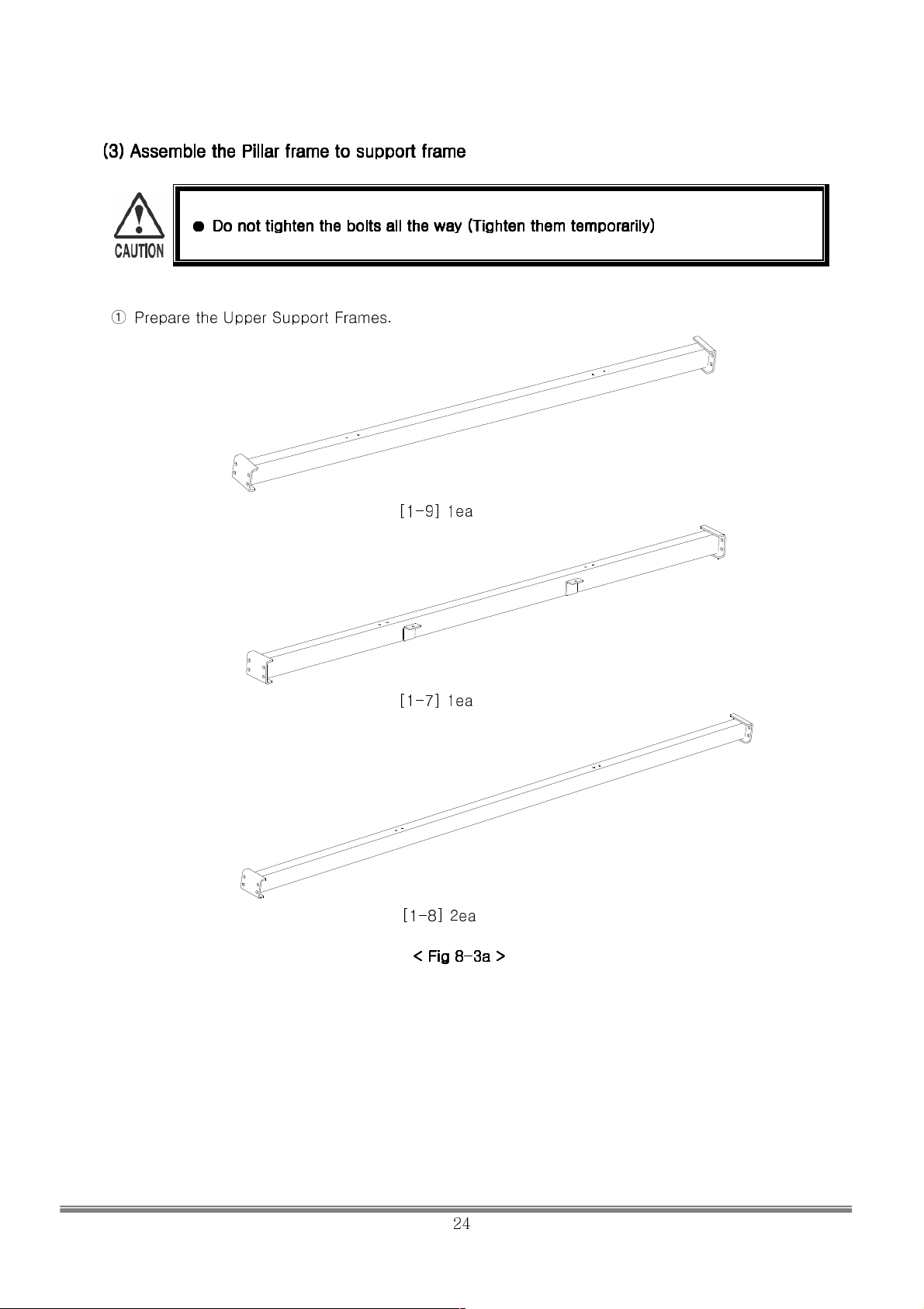
① Prepare the Upper Support Frames.
[1-9] 1ea
[1-7] 1ea
[1-8] 2ea
< Fig 8
< Fig 8----3a >
< Fig 8< Fig 8
3a >
3a >3a >
SIMULINE INC..
24
Page 26
※
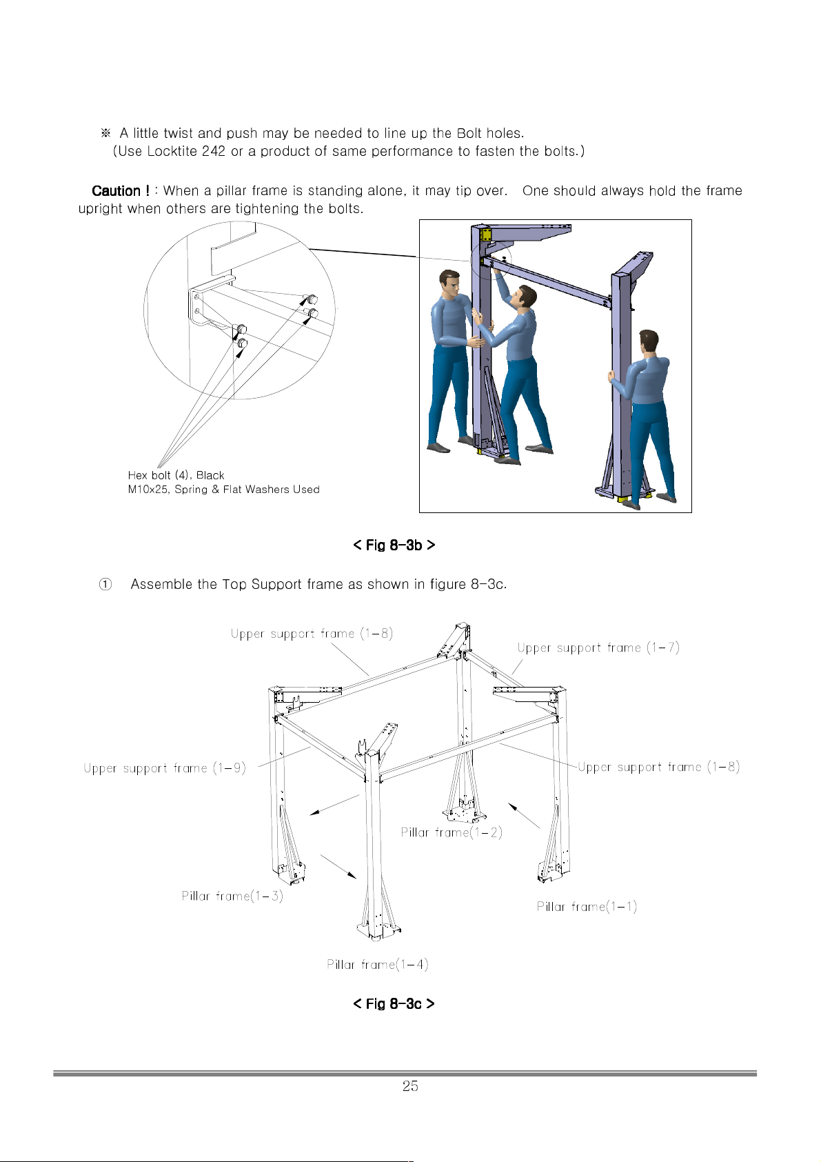
A little twist and push may be needed to line up the Bolt holes.
(Use Locktite 242 or a product of same performance to fasten the bolts.)
Caution !
Caution !
Caution !Caution !
upright when others are tightening the bolts.
: When a pillar frame is standing
Hex bolt (4), Black
M10x25, Spring & Flat Washers Used
alone, it may tip over. One should always hold the frame
< Fig 8
< Fig 8----3b >
< Fig 8< Fig 8
3b >
3b >3b >
① Assemble the Top Support frame as shown in figure 8-3c.
< Fig 8
< Fig 8----3c >
< Fig 8< Fig 8
3c >
3c >3c >
SIMULINE INC..
25
Page 27
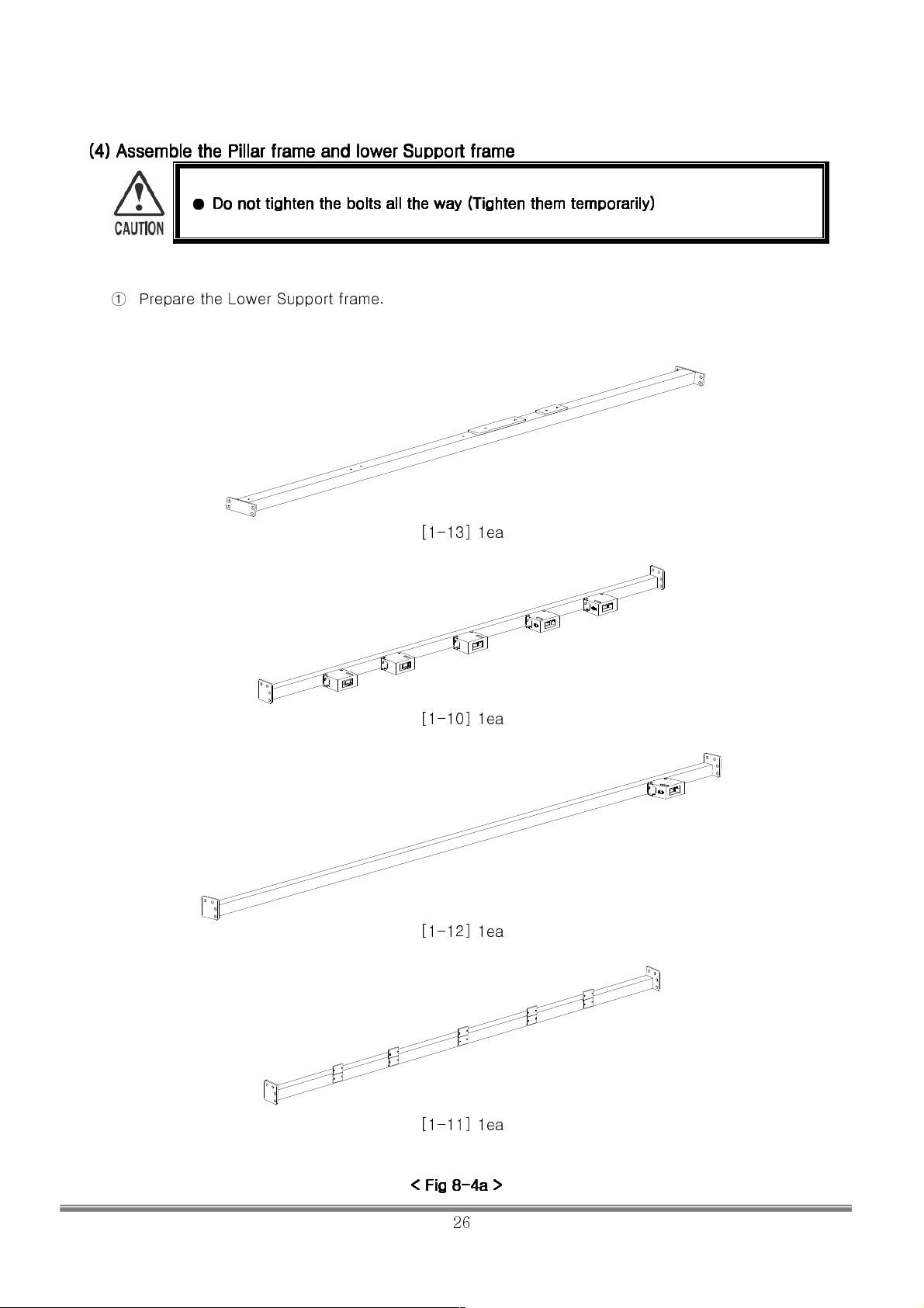
(4) Assemble the Pillar frame and lower Support frame
(4) Assemble the Pillar frame and lower Support frame
(4) Assemble the Pillar frame and lower Support frame(4) Assemble the Pillar frame and lower Support frame
●●●●
Do not tighten the bolts all the way (Tighten them temporarily)
Do not tighten the bolts all the way (Tighten them temporarily)
Do not tighten the bolts all the way (Tighten them temporarily)Do not tighten the bolts all the way (Tighten them temporarily)
① Prepare the Lower Support frame.
[1-13] 1ea
[1-10] 1ea
[1-12] 1ea
[1-11] 1ea
< Fig 8
< Fig 8----4a >
< Fig 8< Fig 8
4a >
4a >4a >
SIMULINE INC..
26
Page 28
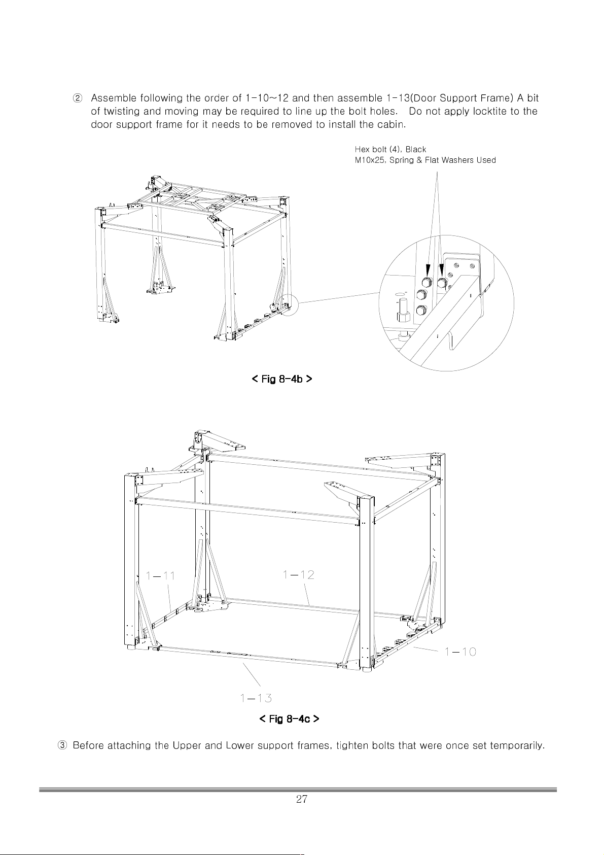
② Assemble following the order of 1-10~12 and then assemble 1-13(Door Support Frame) A bit
of twisting and moving may be required to line up the bolt holes. Do not apply locktite to the
door support frame for it needs to be removed to install the cabin.
Hex bolt (4), Black
M10x25, Spring & Flat Washers Used
< Fig 8
< Fig 8----4b >
< Fig 8< Fig 8
4b >
4b >4b >
< Fig 8
< Fig 8----4c >
< Fig 8< Fig 8
4c >
4c >4c >
③ Before attaching the Upper and Lower support frames, tighten bolts that were once set temporarily.
SIMULINE INC..
27
Page 29
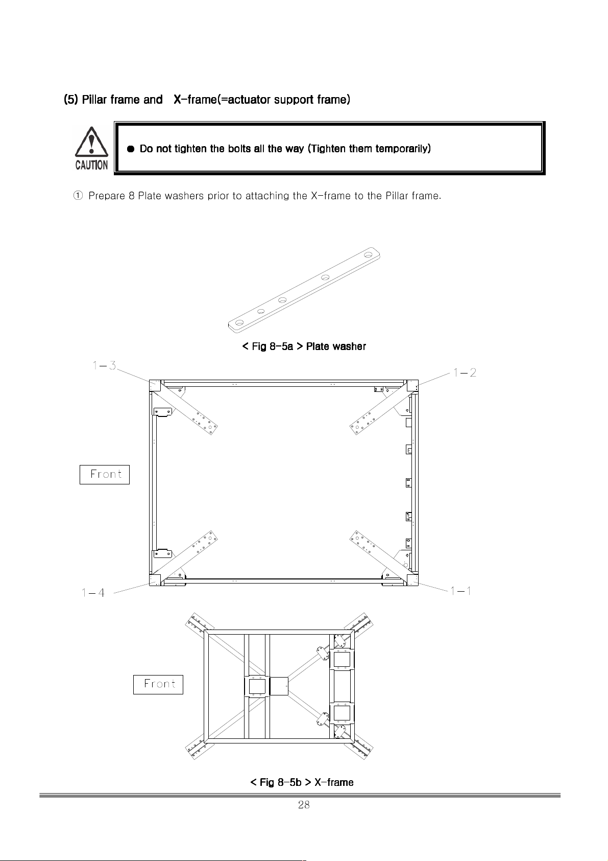
(5) Pillar frame and X
(5) Pillar frame and X----frame(=actuator support frame)
(5) Pillar frame and X (5) Pillar frame and X
frame(=actuator support frame)
frame(=actuator support frame)frame(=actuator support frame)
●●●●
Do not tighten the bolts all the way (Tighten them temporarily)
Do not tighten the bolts all the way (Tighten them temporarily)
Do not tighten the bolts all the way (Tighten them temporarily)Do not tighten the bolts all the way (Tighten them temporarily)
① Prepare 8 Plate washers prior to attaching the X-frame to the Pillar frame.
< Fig 8
< Fig 8----5a > Plate washer
< Fig 8< Fig 8
5a > Plate washer
5a > Plate washer5a > Plate washer
< Fig 8
< Fig 8----5b > X
< Fig 8< Fig 8
5b > X----frame
5b > X5b > X
frame
frameframe
SIMULINE INC..
28
Page 30
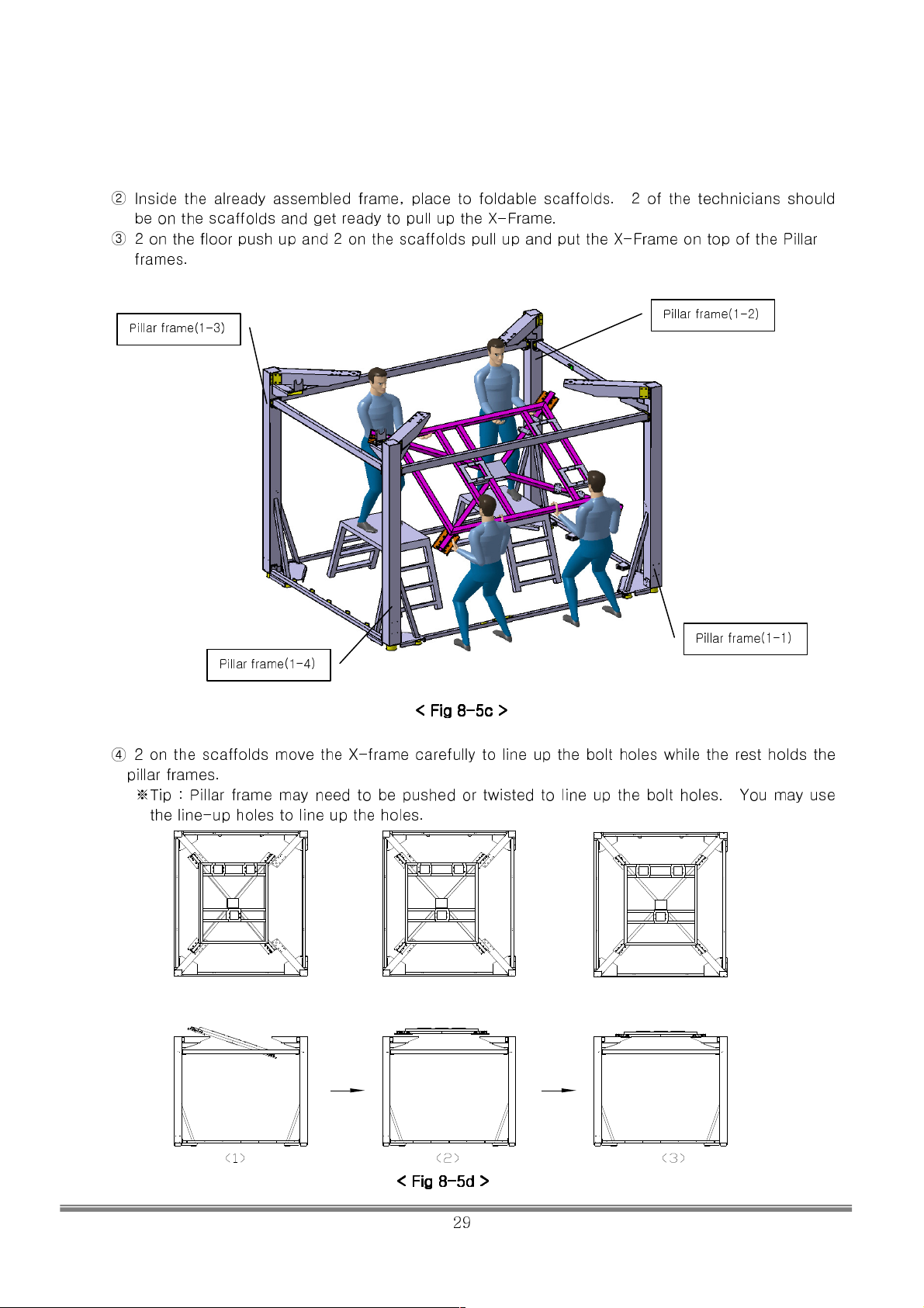
② Inside the already assembled frame, place to foldable scaffolds. 2 of the technicians should
be on the scaffolds and get ready to pull up the X-Frame.
③ 2 on the floor push up and 2 on the scaffolds pull up and put the X-Frame on top of the Pillar
frames.
Pillar frame(1-3)
Pillar frame(1-2)
Pillar frame(1-1)
Pillar frame(1-4)
< Fig 8
< Fig 8----5c >
< Fig 8< Fig 8
5c >
5c >5c >
④ 2 on the scaffolds move the X-frame carefully to line up the bolt holes while the rest holds the
pillar frames.
※Tip : Pillar frame may need to be pushed or twisted to line up the bolt holes. You may use
the line-up holes to line up the holes.
< Fig 8
< Fig 8----5d >
< Fig 8< Fig 8
5d >
5d >5d >
SIMULINE INC..
29
Page 31
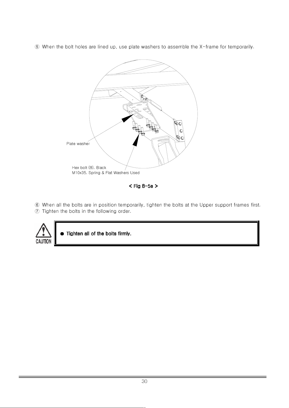
⑤ When the bolt holes are lined up, use plate washers to assemble the X-frame for temporarily.
Plate washer
Hex bolt (8), Black
M10x35, Spring & Flat Washers Used
⑥ When all the bolts are in position temporarily, tighten the bolts at the Upper support frames first.
⑦ Tighten the bolts in the following order.
●●●●
Tighten all of the bolts firmly.
Tighten all of the bolts firmly.
Tighten all of the bolts firmly.Tighten all of the bolts firmly.
< Fig 8
< Fig 8----5e >
< Fig 8< Fig 8
5e >
5e >5e >
SIMULINE INC..
30
Page 32
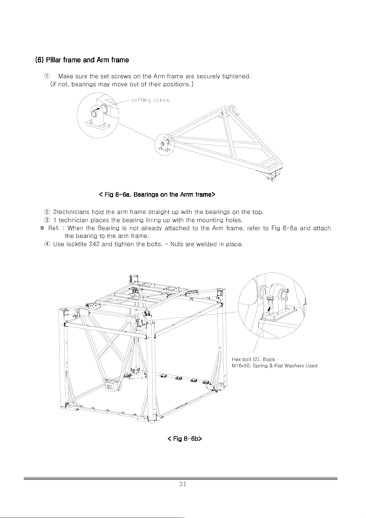
(6) Pillar frame and Arm frame
(6) Pillar frame and Arm frame
(6) Pillar frame and Arm frame(6) Pillar frame and Arm frame
Make sure the set screws on the Arm frame are securely tightened.
①
(if not, bearings may move out of their positions.)
< Fig 8
< Fig 8----6a.
< Fig 8< Fig 8
6a. Bearings on the Arrm frame>
Bearings on the Arrm frame>
6a.6a.
Bearings on the Arrm frame>Bearings on the Arrm frame>
② 2technicians hold the arm frame straight up with the bearings on the top.
③ 1 technician places the bearing lining up with the mounting holes.
※ Ref. : When the Bearing is not already attached to the Arm frame, refer to Fig 8-6a and attach
the bearing to the arm frame.
④ Use locktite 242 and tighten the bolts. – Nuts are welded in place.
Hex bolt (2), Black
M16x50, Spring & Flat Washers Used
< Fig 8
< Fig 8----6b>
< Fig 8< Fig 8
6b>
6b>6b>
SIMULINE INC..
31
Page 33
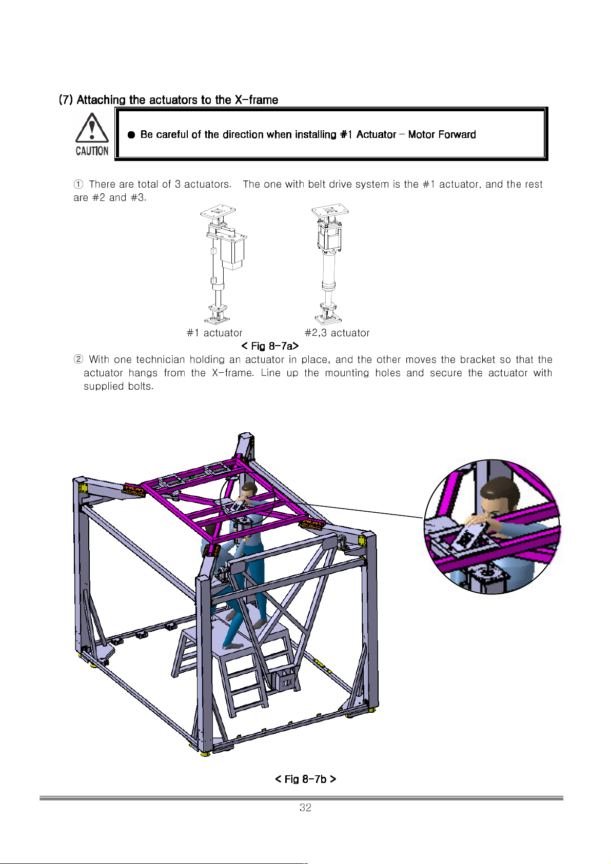
(7) Attaching the actuators to
(7) Attaching the actuators to the
(7) Attaching the actuators to (7) Attaching the actuators to
●●●●
Be careful
Be careful of the direction when installing #1 Actuator
Be careful Be careful
the X
X----frame
X X
frame
frameframe
Motor Forward
Motor Forward Motor Forward
thethe
of the direction when installing #1 Actuator –––– Motor Forward
of the direction when installing #1 Actuator of the direction when installing #1 Actuator
① There are total of 3 actuators. The one with belt drive system is the #1 actuator, and the rest
are #2 and #3.
#1 actuator #2,3 actuator
< Fig 8
< Fig 8----7a>
< Fig 8< Fig 8
② With one technician holding an actuator in place, and the other moves the bracket so that the
actuator hangs from the X-frame. Line up the mounting holes and secure the actuator with
supplied bolts.
7a>
7a>7a>
< Fig 8
< Fig 8----7b >
< Fig 8< Fig 8
7b >
7b >7b >
SIMULINE INC..
32
Page 34
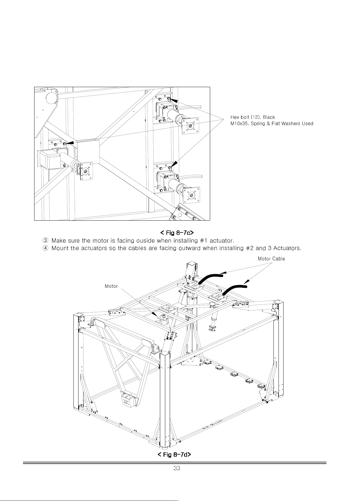
Hex bolt (12), Black
M10x35, Spring & Flat Washers Used
< Fig 8
< Fig 8----7c>
< Fig 8< Fig 8
③ Make sure the motor is facing ouside when installing #1 actuator.
④ Mount the actuators so the cables are facing outward when installing #2 and 3 Actuators.
7c>
7c>7c>
Motor Cable
Motor
< Fig 8
< Fig 8----7d>
< Fig 8< Fig 8
7d>
7d>7d>
SIMULINE INC..
33
Page 35
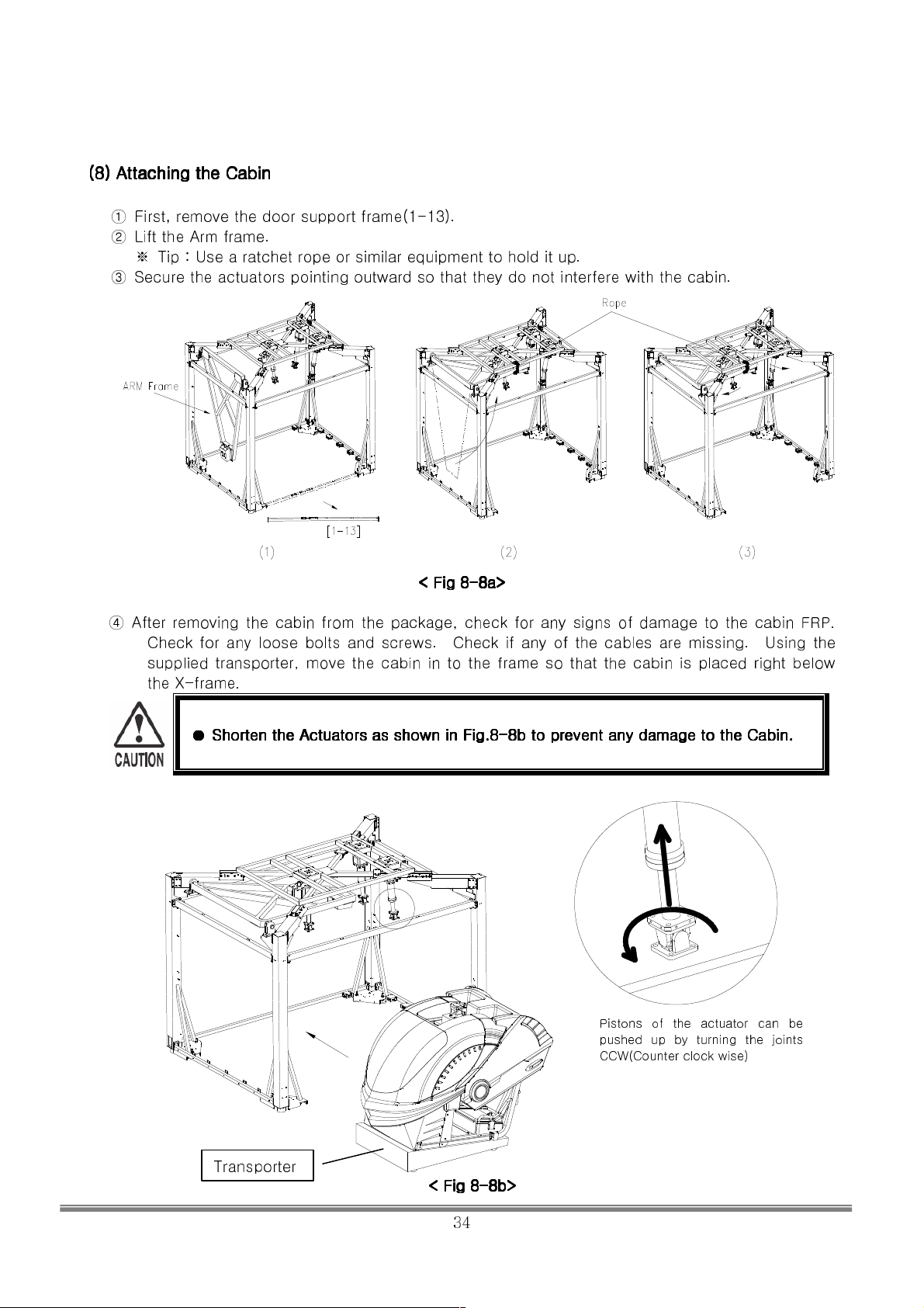
(8) Attaching the Cabin
(8) Attaching the Cabin
(8) Attaching the Cabin (8) Attaching the Cabin
① First, remove the door support frame(1-13).
② Lift the Arm frame.
※ Tip : Use a ratchet rope or similar equipment to hold it up.
③ Secure the actuators pointing outward so that they do not interfere with the cabin.
< Fig 8
< Fig 8----8a>
< Fig 8< Fig 8
④ After removing the cabin from the package, check for any signs of damage to the cabin FRP.
Check for any loose bolts and screws. Check if any of the cables are missing. Using the
supplied transporter, move the cabin in to the frame so that the cabin is placed right below
the X-frame.
8a>
8a>8a>
●●●●
Shorten the Actuators as shown in Fig.8
Shorten the Actuators as shown in Fig.8----8b to prevent any damage to the Cabin.
Shorten the Actuators as shown in Fig.8Shorten the Actuators as shown in Fig.8
8b to prevent any damage to the Cabin.
8b to prevent any damage to the Cabin.8b to prevent any damage to the Cabin.
Pistons of the actuator can be
pushed up by turning the joints
Transporter
< Fig 8
< Fig 8----8b>
< Fig 8< Fig 8
8b>
8b>8b>
CCW(Counter clock wise)
SIMULINE INC..
34
Page 36
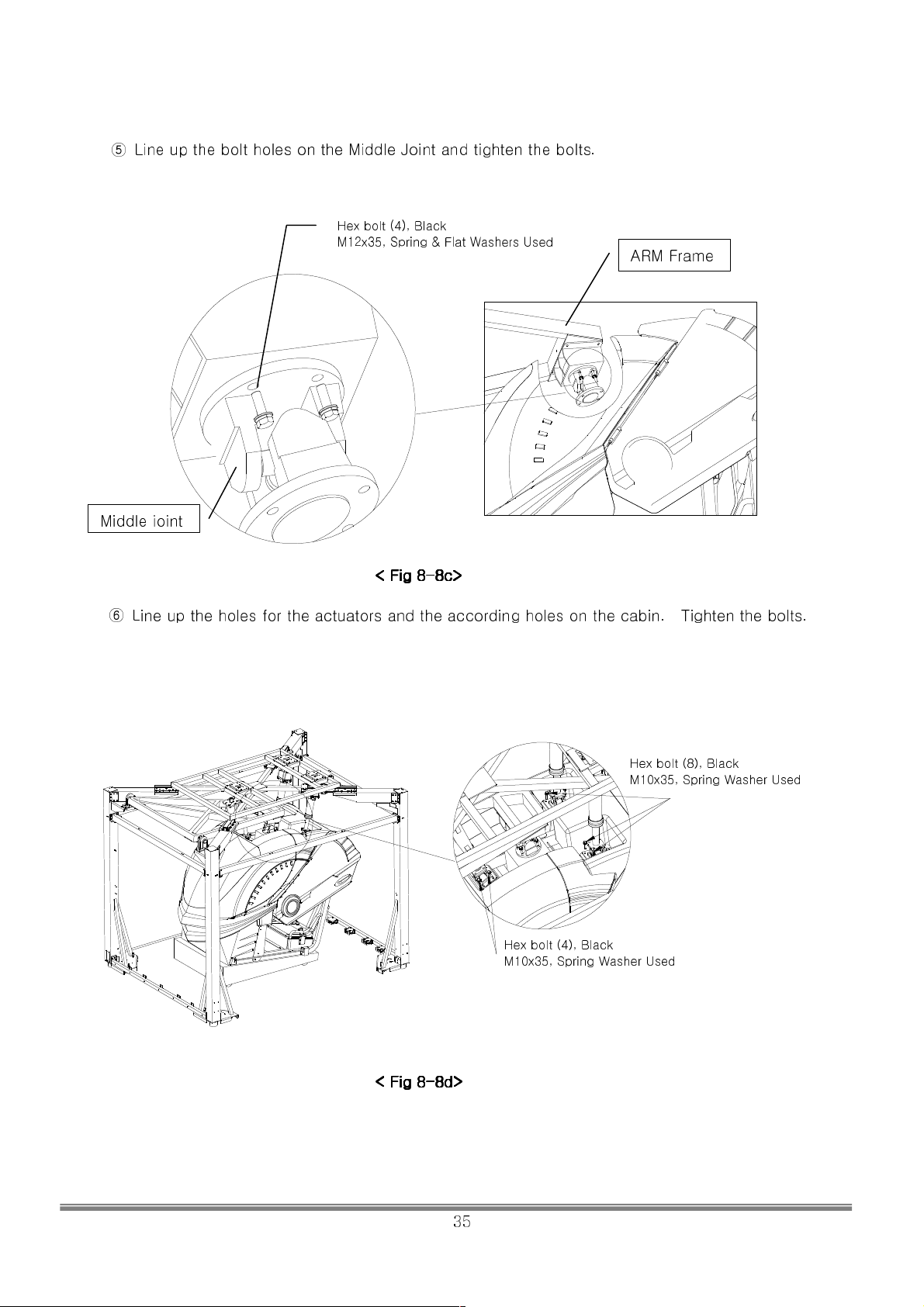
⑤ Line up the bolt holes on the Middle Joint and tighten the bolts.
Hex bolt (4), Black
M12x35, Spring & Flat Washers Used
< Fig 8
< Fig 8----8c>
< Fig 8< Fig 8
8c>
8c>8c>
ARM Frame
⑥ Line up the holes for the actuators and the according holes on the cabin. Tighten the bolts.
< Fig 8
< Fig 8----8888dddd>>>>
< Fig 8< Fig 8
Hex bolt (8), Black
M10x35, Spring Washer Used
Hex bolt (4), Black
M10x35, Spring Washer Used
SIMULINE INC..
35
Page 37
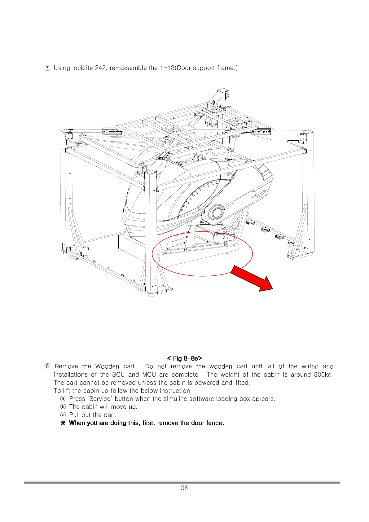
⑦ Using locktite 242, re-assemble the 1-13(Door support frame.)
< Fig 8
< Fig 8----8e>
< Fig 8< Fig 8
⑧ Remove the Wooden cart. Do not remove the wooden cart until all of the wiring and
installations of the SCU and MCU are complete. The weight of the cabin is around 300kg.
The cart cannot be removed unless the cabin is powered and lifted.
To lift the cabin up follow the below instruction :
ⓐ Press ‘Service’ button when the simuline software loading box aprears.
ⓑ The cabin will move up.
ⓒ Pull out the cart.
※
※
When you are doing this,
When you are doing this, first, remove the
※※
When you are doing this, When you are doing this,
first, remove the door fence.
first, remove the first, remove the
8e>
8e>8e>
door fence.
door fence.door fence.
SIMULINE INC..
36
Page 38
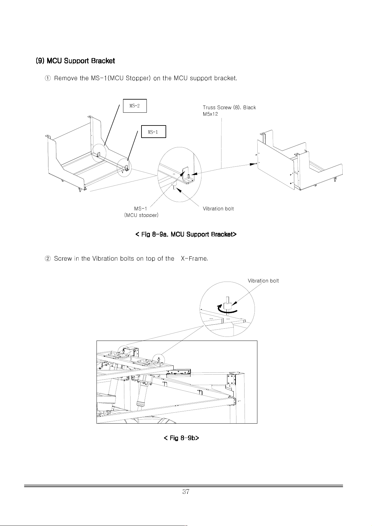
(9) MCU Support Bracket
(9) MCU Support Bracket
(9) MCU Support Bracket (9) MCU Support Bracket
① Remove the MS-1(MCU Stopper) on the MCU support bracket.
MS-2
Truss Screw (8), Black
M5x12
MS-1
MS-1
(MCU stopper)
< Fig 8
< Fig 8----9a.
< Fig 8< Fig 8
9a. MCU Support B
MCU Support Bracket
9a.9a.
MCU Support B MCU Support B
Vibration bolt
② Screw in the Vibration bolts on top of the X-Frame.
racket>>>>
racketracket
Vibration bolt
< Fig 8
< Fig 8----9b>
< Fig 8< Fig 8
9b>
9b>9b>
SIMULINE INC..
37
Page 39
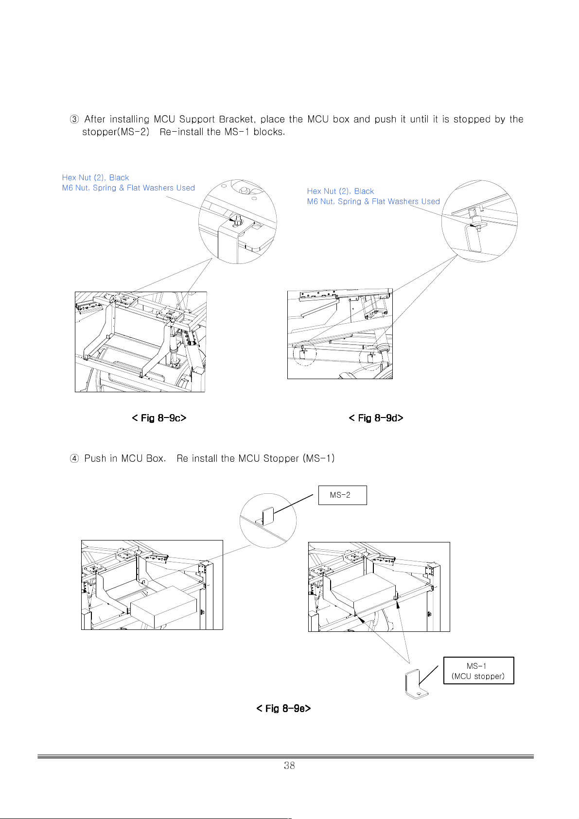
③ After installing MCU Support Bracket, place the MCU box and push it until it is stopped by the
stopper(MS-2) Re-install the MS-1 blocks.
Hex Nut (2), Black
M6 Nut, Spring & Flat Washers Used
Hex Nut (2), Black
M6 Nut, Spring & Flat Washers Used
< Fig 8
< Fig 8----9c
< Fig 8< Fig 8
9c>>>>
< Fig 8
9c9c
< Fig 8----9999dddd>>>>
< Fig 8< Fig 8
④ Push in MCU Box. Re install the MCU Stopper (MS-1)
MS-2
MS-1
(MCU stopper)
< Fig 8
< Fig 8----9999eeee>>>>
< Fig 8< Fig 8
SIMULINE INC..
38
Page 40
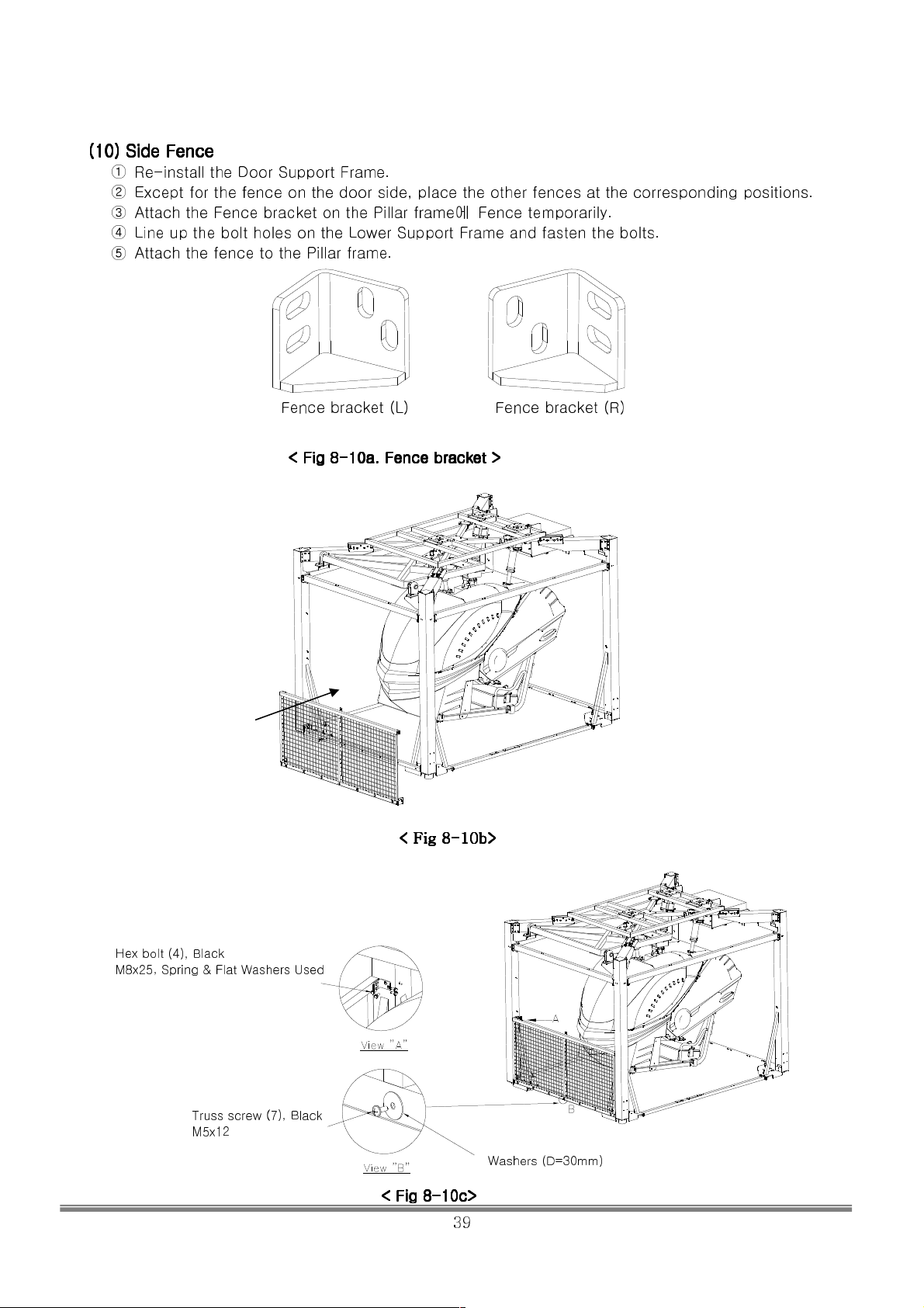
(10) Side Fence
(10) Side Fence
(10) Side Fence (10) Side Fence
① Re-install the Door Support Frame.
② Except for the fence on the door side, place the other fences at the corresponding positions.
③ Attach the Fence bracket on the Pillar frame에
Fence temporarily.
④ Line up the bolt holes on the Lower Support Frame and fasten the bolts.
⑤ Attach the fence to the Pillar frame.
Fence bracket (L) Fence bracket (R)
< Fig 8
< Fig 8----10a. Fence bracket >
< Fig 8< Fig 8
10a. Fence bracket >
10a. Fence bracket >10a. Fence bracket >
Hex bolt (4), Black
M8x25, Spring & Flat Washers Used
Truss screw (7), Black
M5x12
< Fig 8
< Fig 8----10b>
< Fig 8< Fig 8
10b>
10b>10b>
< Fig 8
< Fig 8----10c>
< Fig 8< Fig 8
10c>
10c>10c>
39
Washers (D=30mm)
SIMULINE INC..
Page 41
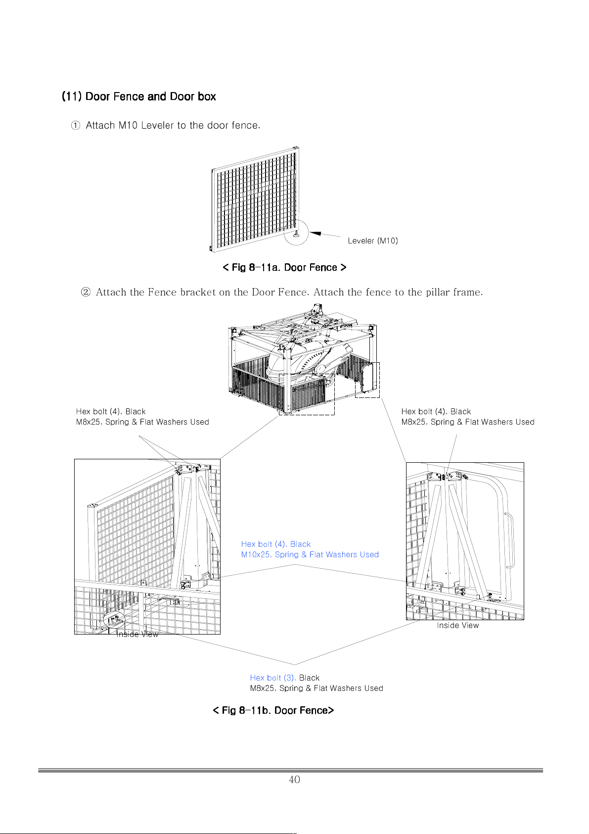
(11) Door Fence and Door box
(11) Door Fence and Door box
(11) Door Fence and Door box (11) Door Fence and Door box
① Attach M10 Leveler to the door fence.
< Fig 8
< Fig 8----11a. Door Fence >
< Fig 8< Fig 8
11a. Door Fence >
11a. Door Fence >11a. Door Fence >
Leveler (M10)
② Attach the Fence bracket on the Door Fence. Attach the fence to the pillar frame.
Hex bolt (4), Black
M8x25, Spring & Flat Washers Used
Hex bolt (4), Black
M10x25, Spring & Flat Washers Used
Hex bolt (4), Black
M8x25, Spring & Flat Washers Used
Inside View
< Fig 8
< Fig 8----11b. Door Fence>
< Fig 8< Fig 8
Hex bolt (3), Black
M8x25, Spring & Flat Washers Used
11b. Door Fence>
11b. Door Fence>11b. Door Fence>
Inside View
SIMULINE INC..
40
Page 42
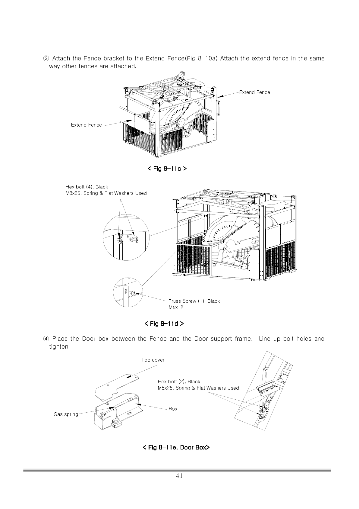
③ Attach the Fence bracket to the Extend Fence(Fig 8-10a) Attach the extend fence in the same
way other fences are attached.
Extend Fence
Extend Fence
< Fig 8
< Fig 8----11c >
< Fig 8< Fig 8
Hex bolt (4), Black
M8x25, Spring & Flat Washers Used
11c >
11c >11c >
Truss Screw (1), Black
M5x12
< Fig 8
< Fig 8----11d >
< Fig 8< Fig 8
11d >
11d >11d >
④ Place the Door box between the Fence and the Door support frame. Line up bolt holes and
tighten.
Top cover
Hex bolt (2), Black
M8x25, Spring & Flat Washers Used
Gas spring
Box
< Fig 8
< Fig 8----11e. Door
< Fig 8< Fig 8
11e. Door Box>
11e. Door11e. Door
Box>
Box> Box>
SIMULINE INC..
41
Page 43
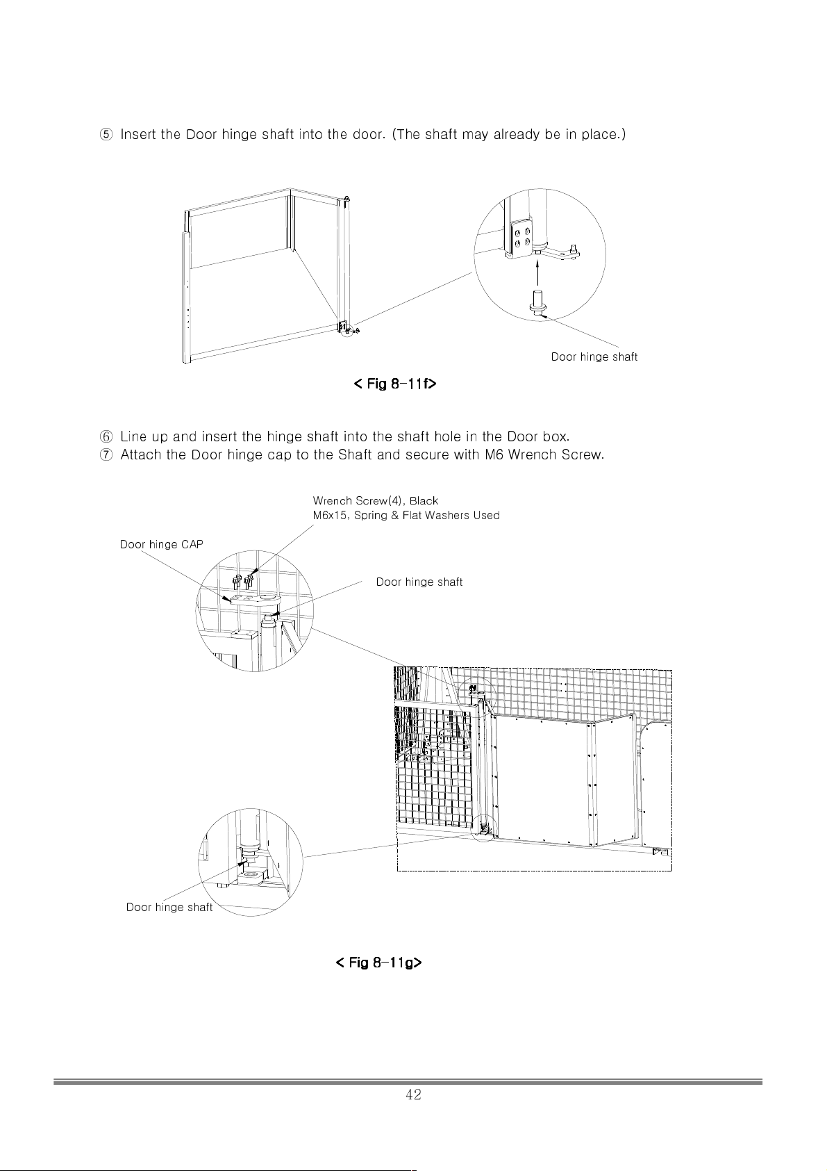
⑤ Insert the Door hinge shaft into the door. (The shaft may already be in place.)
Door hinge shaft
< Fig 8
< Fig 8----11f>
< Fig 8< Fig 8
⑥
Line up and insert the hinge shaft into the shaft hole in the Door box.
⑦ Attach the Door hinge cap to the Shaft and secure with M6 Wrench Screw.
Door hinge CAP
Wrench Screw(4), Black
M6x15, Spring & Flat Washers Used
11f>
11f>11f>
Door hinge shaft
Door hinge shaft
< Fig 8
< Fig 8----11g>
< Fig 8< Fig 8
11g>
11g>11g>
42
SIMULINE INC..
Page 44
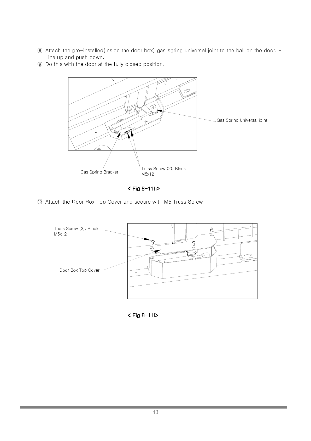
⑧ Attach the pre-installed(inside the door box) gas spring universal joint to the ball on the door. –
Line up and push down.
⑨ Do this with the door at the fully closed position.
Gas Spring Universal joint
Gas Spring Bracket
Truss Screw (2), Black
M5x12
< Fig 8
< Fig 8----11h>
< Fig 8< Fig 8
⑩ Attach the Door Box Top Cover and secure with M5 Truss Screw.
11h>
11h>11h>
Truss Screw (3), Black
M5x12
Door Box Top Cover
< Fig 8
< Fig 8----11i>
< Fig 8< Fig 8
11i>
11i>11i>
SIMULINE INC..
43
Page 45
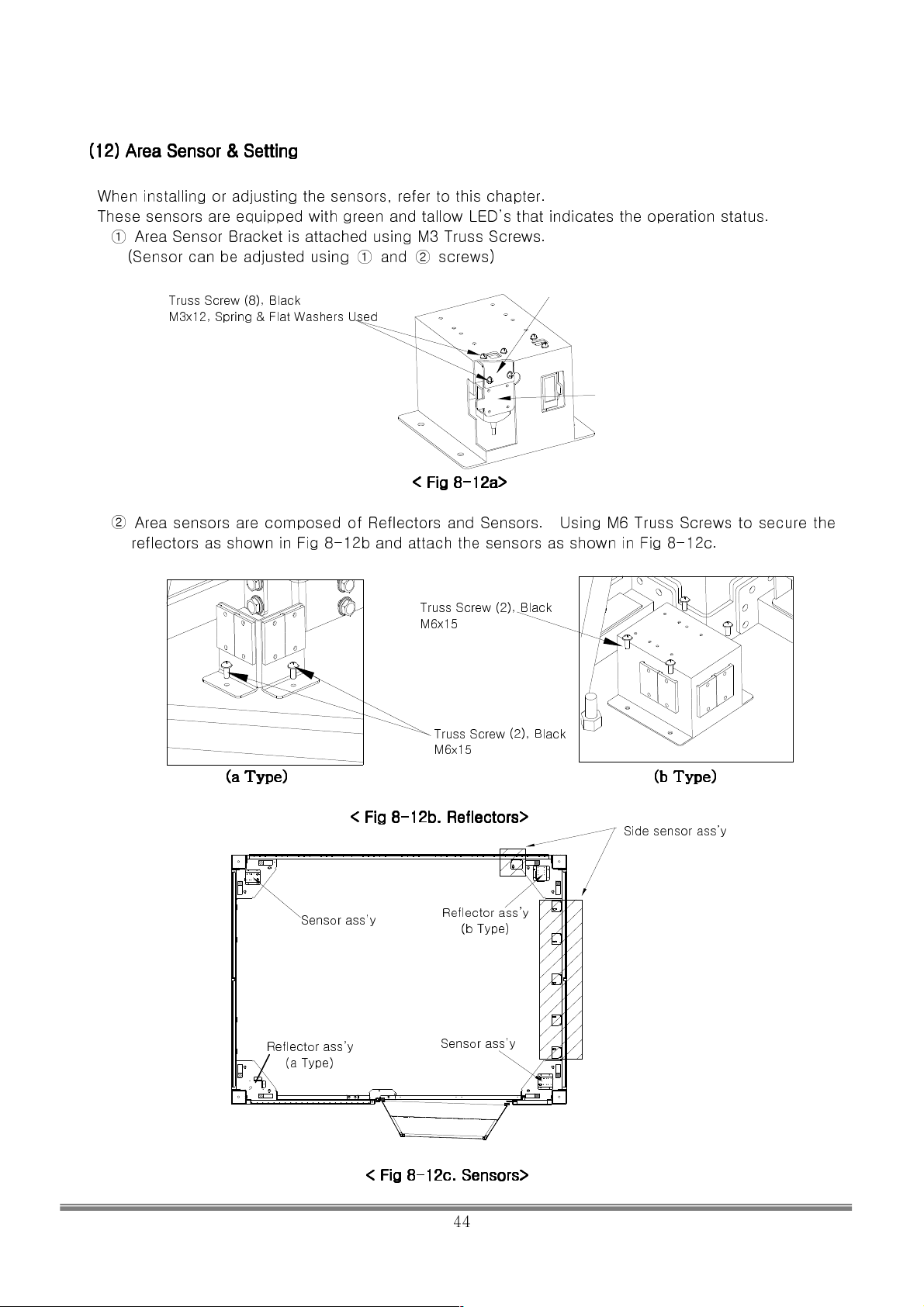
(12) Area Sensor & Setting
(12) Area Sensor & Setting
(12) Area Sensor & Setting(12) Area Sensor & Setting
When installing or adjusting the sensors, refer to this chapter.
These sensors are equipped with green and tallow LED’s that indicates the operation status.
① Area Sensor Bracket is attached using M3 Truss Screws.
(Sensor can be adjusted using ① and ② screws)
Truss Screw (8), Black
M3x12, Spring & Flat Washers Used
①
②
② Area sensors are composed of Reflectors and Sensors. Using M6 Truss Screws to secure the
reflectors as shown in Fig 8-12b and attach the sensors as shown in Fig 8-12c.
< Fig 8
< Fig 8----12a>
< Fig 8< Fig 8
12a>
12a>12a>
Truss Screw (2), Black
M6x15
Truss Screw (2), Black
M6x15
(a Type) (b Type)
(a Type) (b Type)
(a Type) (b Type) (a Type) (b Type)
< Fig 8
Sensor ass’y
Reflector ass’y
(a Type)
< Fig 8----12b. Reflectors>
< Fig 8< Fig 8
12b. Reflectors>
12b. Reflectors>12b. Reflectors>
Reflector ass’y
(b Type)
Sensor ass’y
Side sensor ass’y
< Fig 8
< Fig 8----12c. Sensors>
< Fig 8< Fig 8
12c. Sensors>
12c. Sensors>12c. Sensors>
SIMULINE INC..
44
Page 46
② Adjust the sensors so the beams from them point the centers of the reflectors. Use a white
sheet of paper to track the beam.
④
If the ye
remove any obstacles.
llow LED on the sensor keeps blinking, or off, please check around the sensors and
SIMULINE INC..
45
Page 47
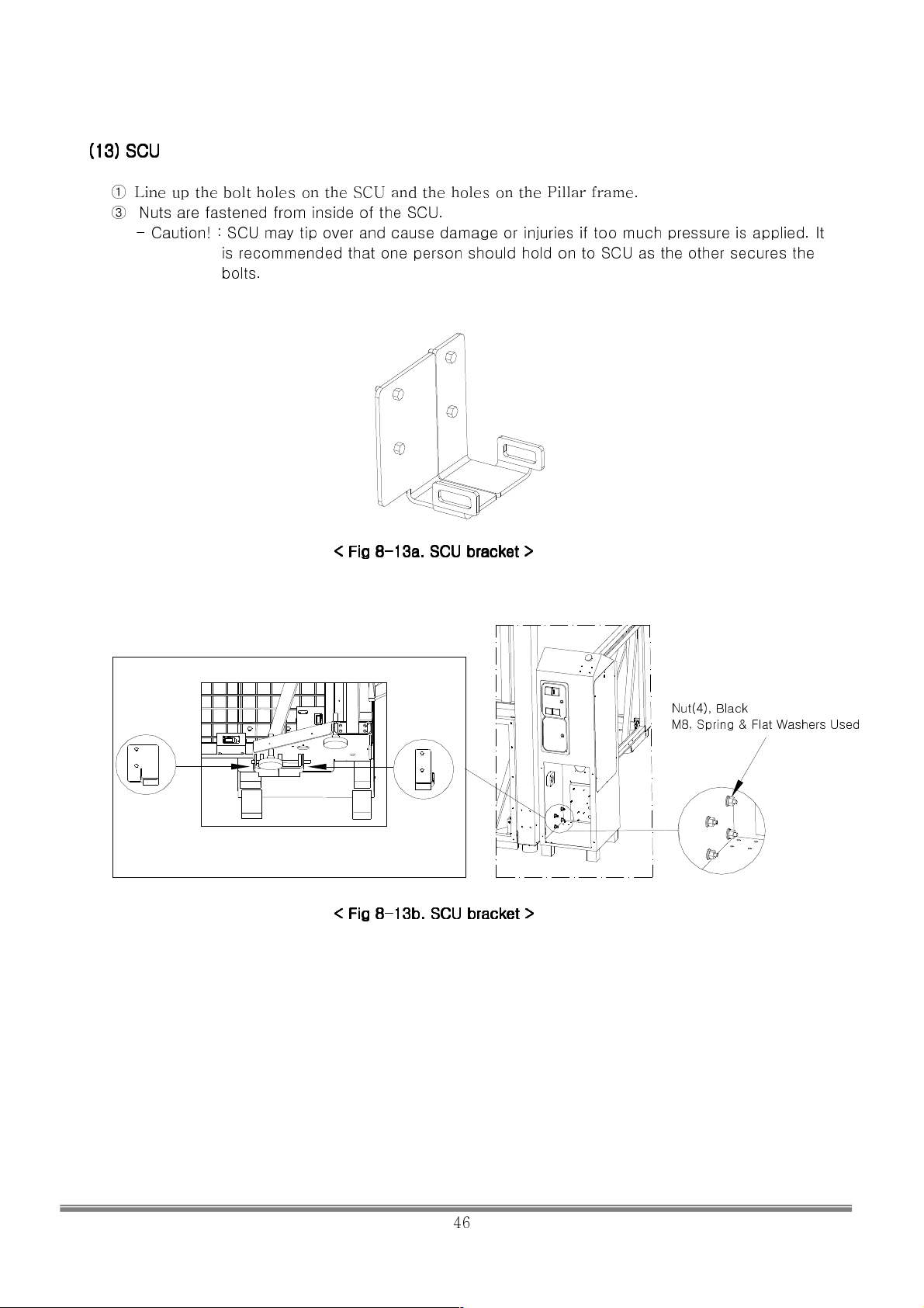
(13) SCU
(13) SCU
(13) SCU (13) SCU
①
③ Nuts are fastened from inside of the SCU.
Line up the bolt holes on the SCU and the holes on the Pillar frame.
- Caution! : SCU may tip over and cause damage or injuries if too much pressure is applied. It
is recommended that one person should hold on to SCU as the other secures the
bolts.
< Fig 8
< Fig 8----13a. SCU bracket >
< Fig 8< Fig 8
13a. SCU bracket >
13a. SCU bracket >13a. SCU bracket >
Nut(4), Black
M8, Spring & Flat Washers Used
< Fig 8
< Fig 8----13b. SCU brac
< Fig 8< Fig 8
13b. SCU bracket >
13b. SCU brac13b. SCU brac
ket >
ket >ket >
SIMULINE INC..
46
Page 48
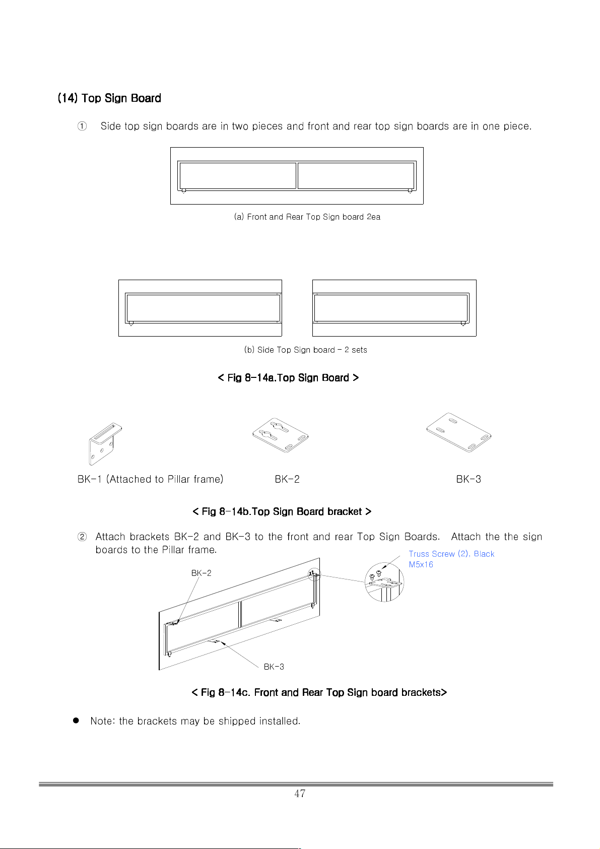
(14)
(14) Top Sign Board
Top Sign Board
(14) (14)
Top Sign BoardTop Sign Board
① Side top sign boards are in two pieces and front and rear top sign boards are in one piece.
(a) Front and Rear Top Sign board 2ea
(b) Side Top Sign board – 2 sets
< Fig 8
< Fig 8----14a.Top Sign Board >
< Fig 8< Fig 8
14a.Top Sign Board >
14a.Top Sign Board >14a.Top Sign Board >
BK-1 (Attached to Pillar frame) BK-2 BK-3
< Fig 8
< Fig 8----14b.Top Sign Board bracket >
< Fig 8< Fig 8
② Attach brackets BK-2 and BK-3 to the front and rear Top Sign Boards. Attach the the sign
boards to the Pillar frame.
BK-2
< Fig
< Fig 8888----14c. Front and Rear Top Sign board brackets>
< Fig < Fig
14b.Top Sign Board bracket >
14b.Top Sign Board bracket >14b.Top Sign Board bracket >
Truss Screw (2), Black
M5x16
BK-3
14c. Front and Rear Top Sign board brackets>
14c. Front and Rear Top Sign board brackets>14c. Front and Rear Top Sign board brackets>
Note: the brackets may be shipped installed.
SIMULINE INC..
47
Page 49
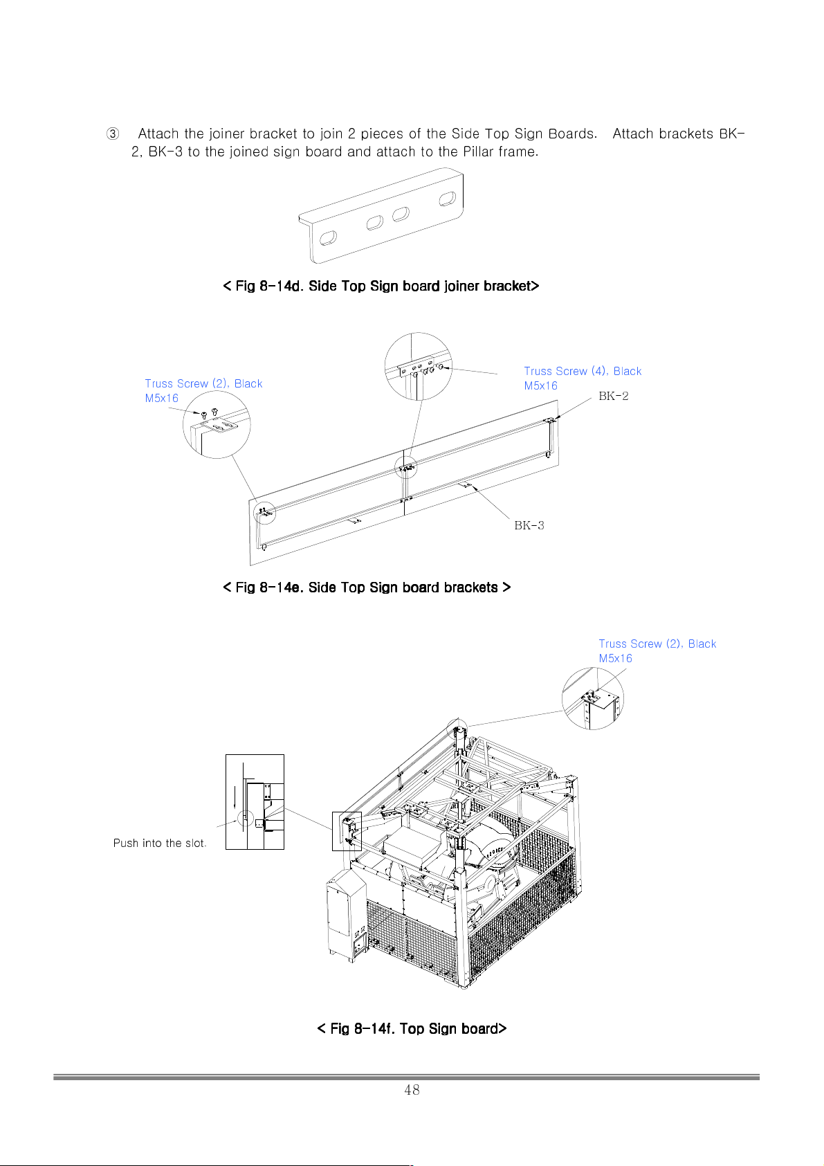
③ Attach the joiner bracket to join 2 pieces of the Side Top Sign Boards. Attach brackets BK-
2, BK-3 to the joined sign board and attach to the Pillar frame.
< Fig 8
< Fig 8----14d.
< Fig 8< Fig 8
14d. Side
Side Top Sign board
14d. 14d.
Top Sign board joiner
SideSide
Top Sign board Top Sign board
joiner bracket>
bracket>
joinerjoiner
bracket> bracket>
Truss Screw (2), Black
M5x16
Truss Screw (4), Black
M5x16
BK-3
BK-2
< Fig 8
< Fig 8----14e. Side
< Fig 8< Fig 8
14e. Side Top Sign board brackets >
14e. Side14e. Side
Top Sign board brackets >
Top Sign board brackets > Top Sign board brackets >
Truss Screw (2), Black
M5x16
Push into the slot.
< Fig 8
< Fig 8----14f. Top Sign board>
< Fig 8< Fig 8
14f. Top Sign board>
14f. Top Sign board>14f. Top Sign board>
SIMULINE INC..
48
Page 50
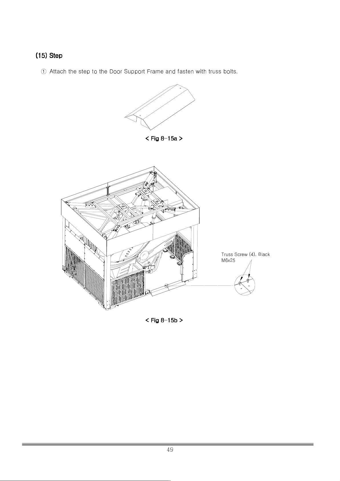
(15) Step
(15) Step
(15) Step(15) Step
① Attach the step to the Door Support Frame and fasten with truss bolts.
< Fig 8
< Fig 8----15a >
< Fig 8< Fig 8
15a >
15a >15a >
Truss Screw (4), Black
M6x25
< Fig 8
< Fig 8----15b >
< Fig 8< Fig 8
15b >
15b >15b >
SIMULINE INC..
49
Page 51
(16)
(16) Power
Power Cable
(16) (16)
Power Power
①
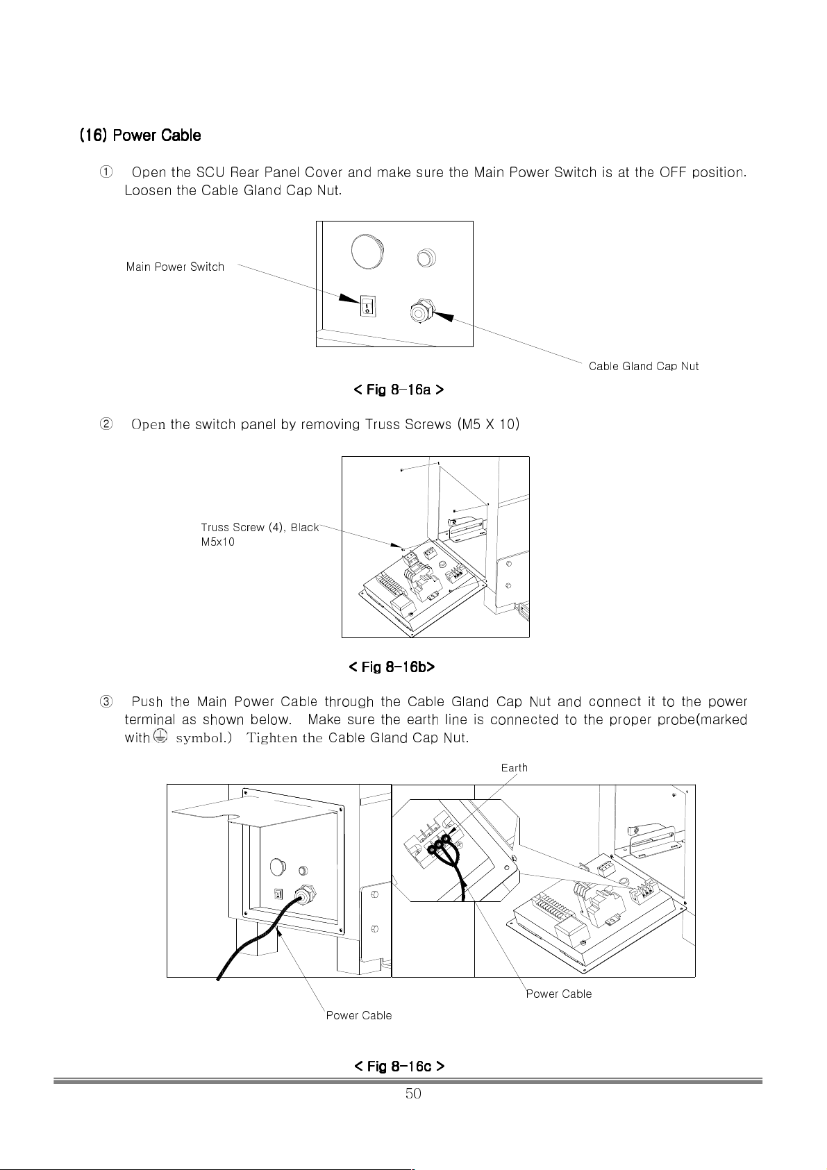
Open the SCU Rear Panel Cover and make sure the Main Power Switch is at the OFF position.
Loosen the Cable Gland Cap Nut.
Main Power Switch
Cable
CableCable
< Fig 8
< Fig 8----16a
< Fig 8< Fig 8
16a >
16a16a
>
> >
Cable Gland Cap Nut
② Open
③
the switch panel by removing Truss Screws (M5 X 10)
Truss Screw (4), Black
M5x10
< Fig 8
< Fig 8----16b
< Fig 8< Fig 8
Push the Main Power Cable through the Cable Gland Cap Nut and connect it to the power
terminal as shown below. Make sure the earth line is connected to the proper probe(marked
with
symbol.) Tighten the
Cable Gland Cap Nut.
16b>>>>
16b16b
Earth
Power Cable
Power Cable
< Fig 8
< Fig 8----16c
< Fig 8< Fig 8
16c >
>
16c16c
> >
SIMULINE INC..
50
Page 52
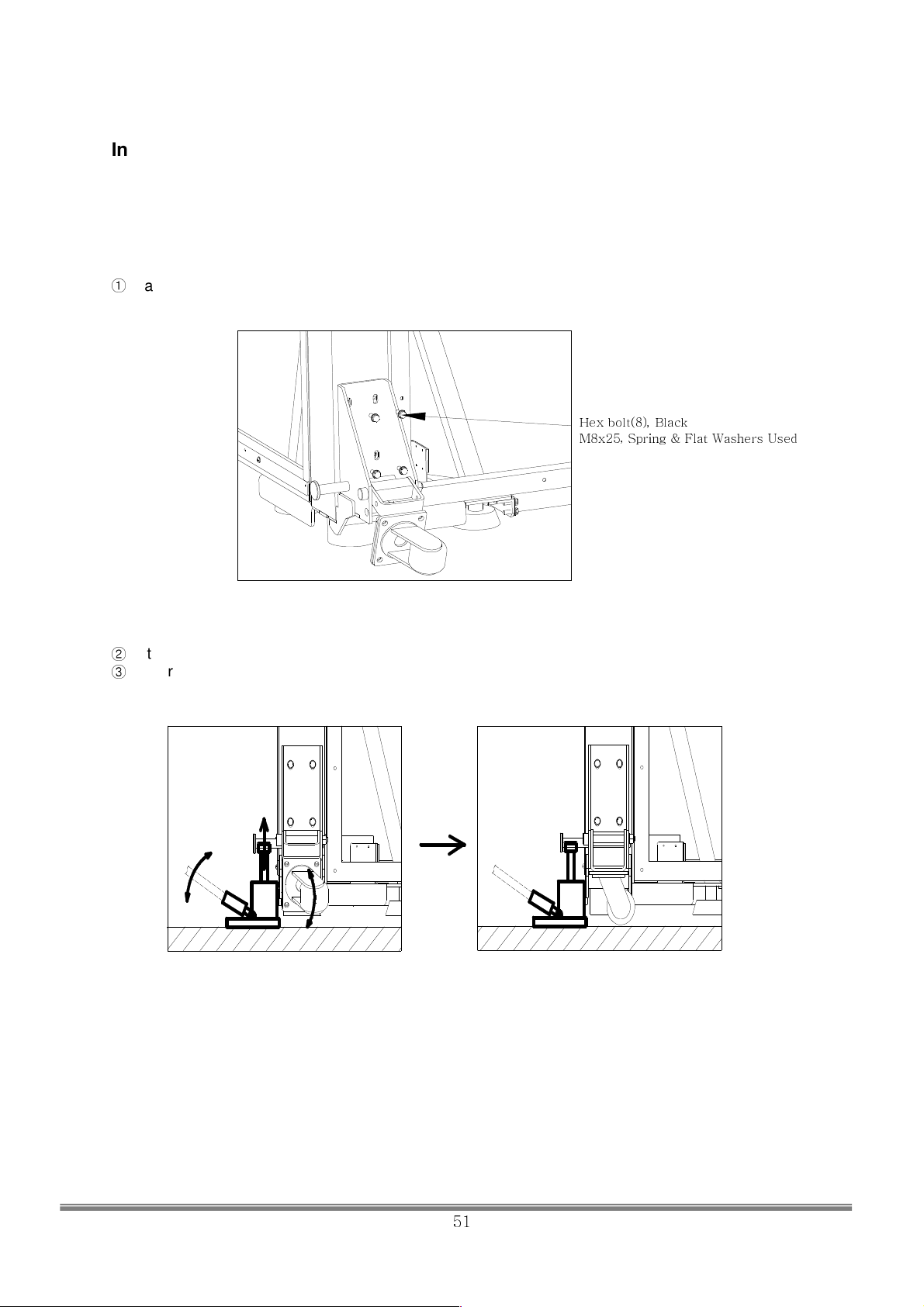
Installing Caster ※※※※ – Optional use at the site.
Option Caster is sold separately in case a user requests in order for easy movement within the shop by
caster without disassembling the frames
■ Installing Caster
①
Place the Caster Set on the Pillar Frame and tighten with M8 bolts.
Hex bolt(8), Black
M8x25, Spring & Flat Washers Used
< Fig 1>
②
Lift the Pillar frame up by about 60cm from the floor by using hydraulic pressure jack or manual jack.
③
Lower the caster of the Caster Set
< Fig 2>
SIMULINE INC..
51
Page 53
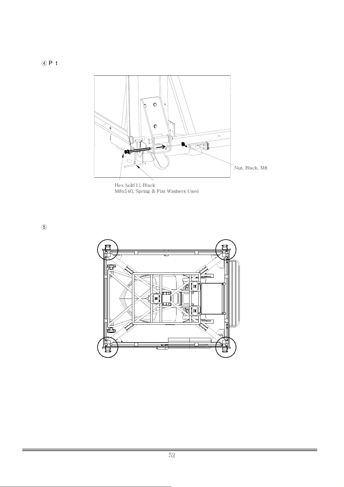
④
Put the fixation bolt in the fixation hole of the Caster Set and then tighten with nut.
Nut, Black, M8
Release the pressure jockey to lower the Pillar frame. So the Casters are grounded. ⑤
Hex bolt(1), Black
M8x140, Spring & Flat Washers Used
< Fig 3>
< Fig 4. Position of Caster Set>
SIMULINE INC..
52
Page 54
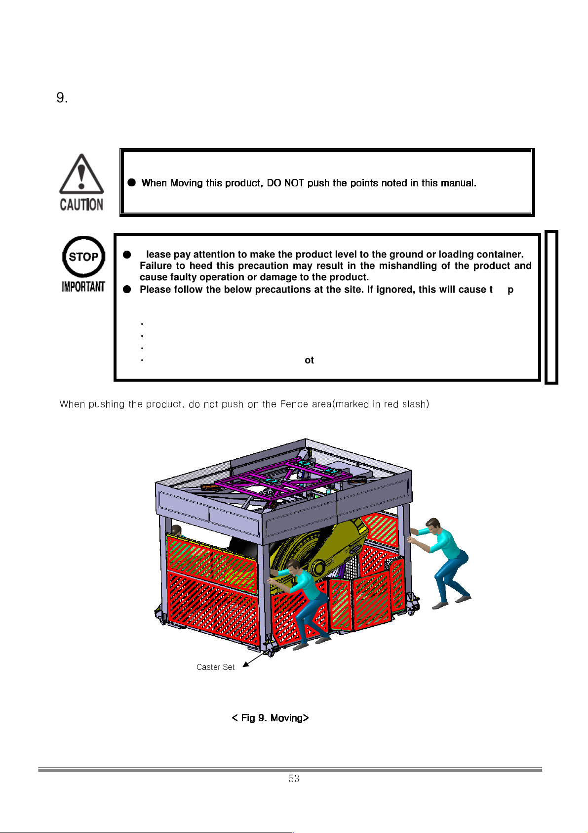
9.
9. When moving the product at a site
When moving the product at a site
9. 9.
When moving the product at a siteWhen moving the product at a site
●
When Moving this product, DO NOT push the points noted in this manual.
When Moving this product, DO NOT push the points noted in this manual.
When Moving this product, DO NOT push the points noted in this manual.When Moving this product, DO NOT push the points noted in this manual.
●
Please pay attention to make the product level to the ground or loading container.
Failure to heed this precaution may result in the mishandling of the product and
cause faulty operation or damage to the product.
●
Please follow the below precautions at the site. If ignored, this will cause the parts
damage or damage to the floor.
▪
Transport the product on a flat floor.
▪
On a slant area with 1cm or more, use a ramp.
▪
Transport the product at a speed of less than 2km/h
▪
Do not tilt too much. Be careful not to apply the load to only one side.
When pushing the product, do not push on the Fence area(marked in red slash)
Caster Set
< Fig 9.
< Fig 9. Moving
< Fig 9. < Fig 9.
Moving>>>>
MovingMoving
SIMULINE INC..
53
Page 55
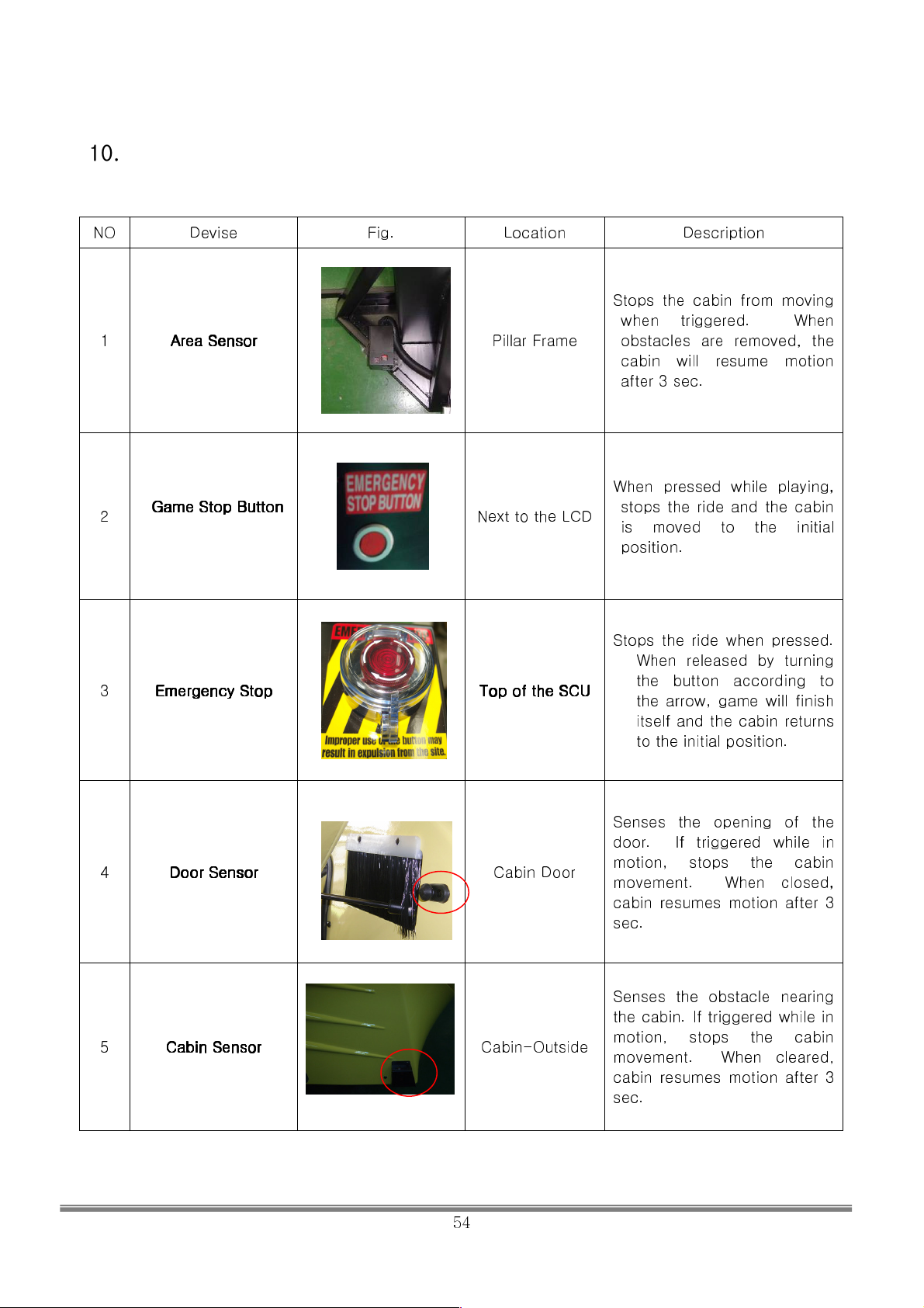
10.
10. Safety Features
Safety Features
10. 10.
Safety FeaturesSafety Features
NO
1
2
3
Devise Fig. Location Description
Stops the cabin from moving
when triggered. When
Area Sensor
Area Sensor
Area SensorArea Sensor
Game
Game Stop Button
Stop Button
GameGame
Stop Button Stop Button
Emergency Stop
Emergency Stop
Emergency Stop Emergency Stop
Pillar Frame
Next to the LCD
Top of the
Top of the SCU
Top of the Top of the
obstacles are removed, the
cabin will resume motion
after 3 sec.
SCU
SCUSCU
When pressed while playing,
stops the ride and the cabin
is moved to the initial
position.
Stops the ride when pressed.
When released by turning
the button according to
the arrow, game will finish
itself and the cabin returns
to the initial position.
4
5
Door Sensor
Door Sensor
Door SensorDoor Sensor
Cabin Sensor
Cabin Sensor
Cabin SensorCabin Sensor
Senses the opening of the
door. If triggered while in
Cabin Door
Cabin-Outside
SIMULINE INC..
54
motion, stops the cabin
movement. When closed,
cabin resumes motion after 3
sec.
Senses the obstacle nearing
the cabin. If triggered while in
motion, stops the cabin
movement. When cleared,
cabin resumes motion after 3
sec.
Page 56
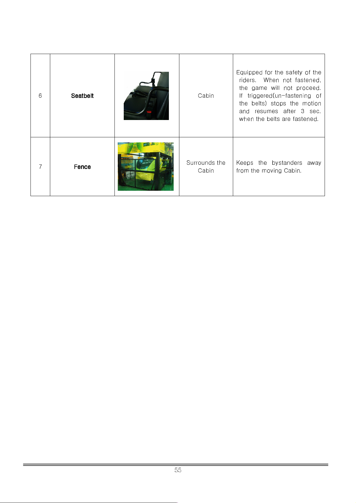
Equipped for the safety of the
the game will not proceed.
riders. When not fastened,
6
7
Seatbelt
Seatbelt
SeatbeltSeatbelt
Fence
Fence
FenceFence
Surrounds the
Cabin
Cabin
If triggered(un-fastening of
the belts) stops the motion
and resumes after 3 sec.
when the belts are fastened.
Keeps the bystanders away
from the moving Cabin.
SIMULINE INC..
55
Page 57
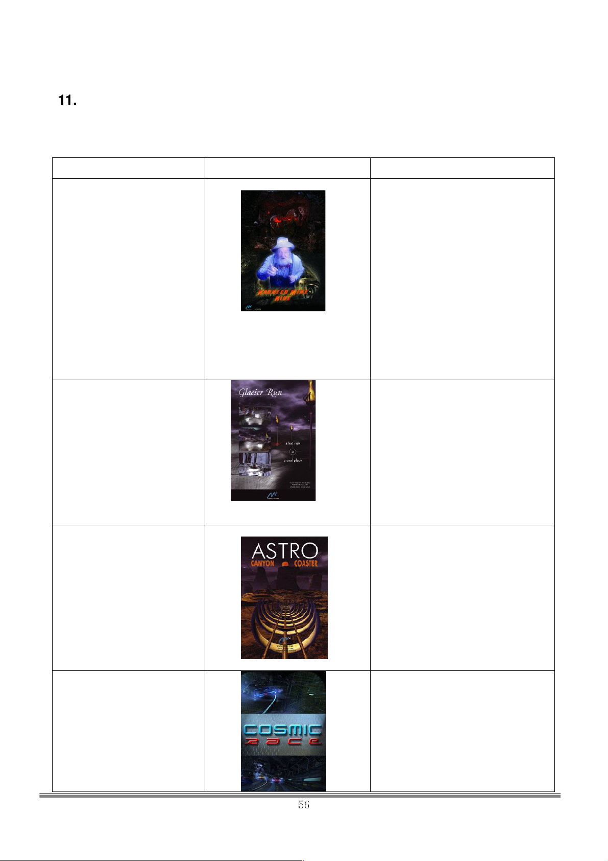
11. Description of Rides
■ ABOUT THE RIDE
Mini-Rider 2 includes 4 rides and passenger can choose one ride from the rides.
Title Image Content
Haunted_Mine
Glacier Run
Hang on to your ten-gallon hats as
you plunge
headfirst into an old, dilapidated gold
mine that
just happens to be haunted… Inside
this hotbed
of mystery and suspense you’ll come
face to face
with the mine’s ghostly prospector
who’ll warn you
not to venture further – but your
insatiable appetite
for adventure will disagree! Only your
quick thinking
(and a little luck) can get you out
alive.
A white-knuckle experience with
dazzling imagery.
This nonstop action ride (a cross
between a bobsled
and a roller coaster), designed to
make your senses
erupt, will take you to the frozen
landscapes of the
Arctic during the Northern Lights
season.
Astro Canyon
Cosmic Race
SIMULINE INC..
56
Hold on for a wild ride in a Grand
Canyon-like environment
in outer space.
Fasten your seat belt and get ready
for the race. Futuristic race will
surely give you the experience you’d
never had before.
Page 58

12. Ride Operation Instruction
1. Make sure the cabin is initialized before boarding.
2. Make sure that one of the passengers is on the right side of the seat before boarding
the other. Be sure that both of the passengers do not exceed 240kg.
“Caution” When children are boarding, make sure the child is on the right side of
the seat.
3. Fasten the seat belt and make sure the belts are secure after boarding.
“Caution” The machine will not run if the seat belts are not secured.
4. [Insert Coin(s)] will show up on the screen. – Ride start screen -
<Ride start screen>
5. Insert coins.
6. At the ride selection screen, choose one movie from 4 of the movies. You can do this by pressing the
selection buttons bellow the display.
<Ride selection screen> <Select button>
7. Each films are about 4min long.
8. When the film is finished, ride start screen will show up and the cabin will move to the initial position.
When the cabin stops and the massage on the screen shows up, you may un-fasten the seat belt and get
off the ride.
“Caution” Do not un-fasten the seat belt until the cabin is at the initial position.
SIMULINE INC..
57
Page 59
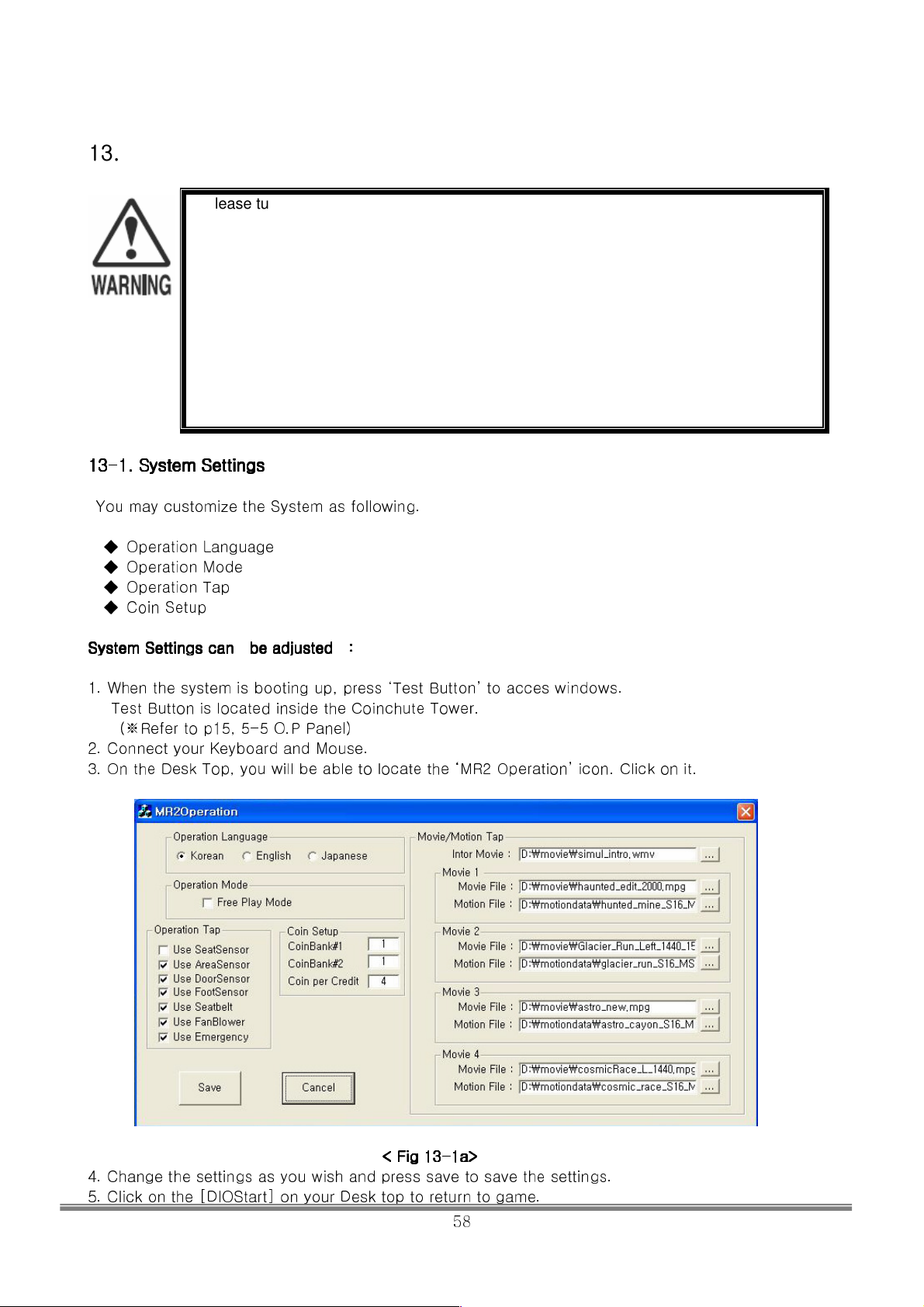
13. System
13. System Operation
13. System 13. System
13
13----1.
1. System
1313
You may customize the System as following.
System
System Settings can be adjusted :
SystemSystem
1. When the system is booting up, press ‘Test Button’ to acces windows.
Test Button is located inside the Coinchute Tower.
2. Connect your Keyboard and Mouse.
3. On the Desk Top, you will be able to locate the ‘MR2 Operation’ icon. Click on it.
System Settings
1. 1.
System System
◆ Operation Language
◆ Operation Mode
◆ Operation Tap
◆ Coin Setup
Settings can be adjusted :
Settings can be adjusted :Settings can be adjusted :
(※Refer to p15, 5-5 O.P Panel)
Operation
OperationOperation
■ Please turn on and turn off individually. Never cut off the power by switching off the
breaker. Follow this manual at all time.
■ When cutting the power off to the MCU, make sure no one is on-board the machine. It
may drop suddenly and this may cause an accidents.
■ Do not switch on and off continuously. When you turn off the machine, wait at least 1
min before you switch it on again. If not, Digital Motion controller may be damaged.
■ 220V DC power is flowing through out the cabin. Servicemen should be certified
engineers. Do not disassemble without Simuline’s consent.
■ MCU and SCU may not be disassembled by an unauthorized personnel.
Settings
SettingsSettings
4. Change the settings as you wish and press save to save the settings.
5. Click on the [DIOStart] on your Desk top to return to game.
< Fig 13
< Fig 13----1a>
< Fig 13 < Fig 13
1a>
1a>1a>
58
SIMULINE INC..
Page 60
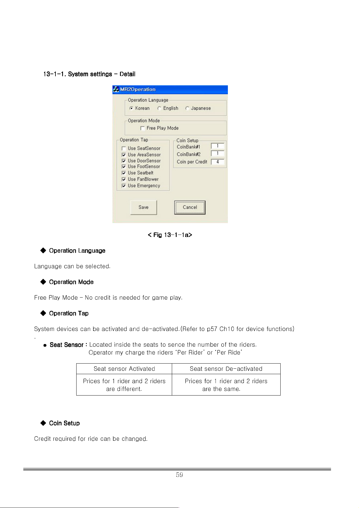
13
13----1111----1.
1. System
1313
System settings
1. 1.
System System
settings ---- Detail
settings settings
Detail
Detail Detail
< Fig 13
< Fig 13----1111----1a>
< Fig 13< Fig 13
1a>
1a>1a>
◆
◆ Operation Language
Operation Language
◆◆
Operation Language Operation Language
Language can be selected.
◆◆◆◆ Operation Mode
Operation Mode
Operation Mode Operation Mode
Free Play Mode – No credit is needed for game play.
◆◆◆◆ Operation Tap
Operation Tap
Operation Tap Operation Tap
System devices can be activated and de-activated.(Refer to p57 Ch10 for device functions)
.
●
Seat Sensor :
Seat Sensor :
Seat Sensor : Seat Sensor :
Located inside the seats to sence the number of the riders.
Operator my charge the riders ‘Per Rider’ or ‘Per Ride’
Seat sensor Activated Seat sensor De-activated
Prices for 1 rider and 2 riders
are different.
Prices for 1 rider and 2 riders
are the same.
◆◆◆◆ Coin Setup
Coin Setup
Coin Setup Coin Setup
Credit required for ride can be changed.
SIMULINE INC..
59
Page 61
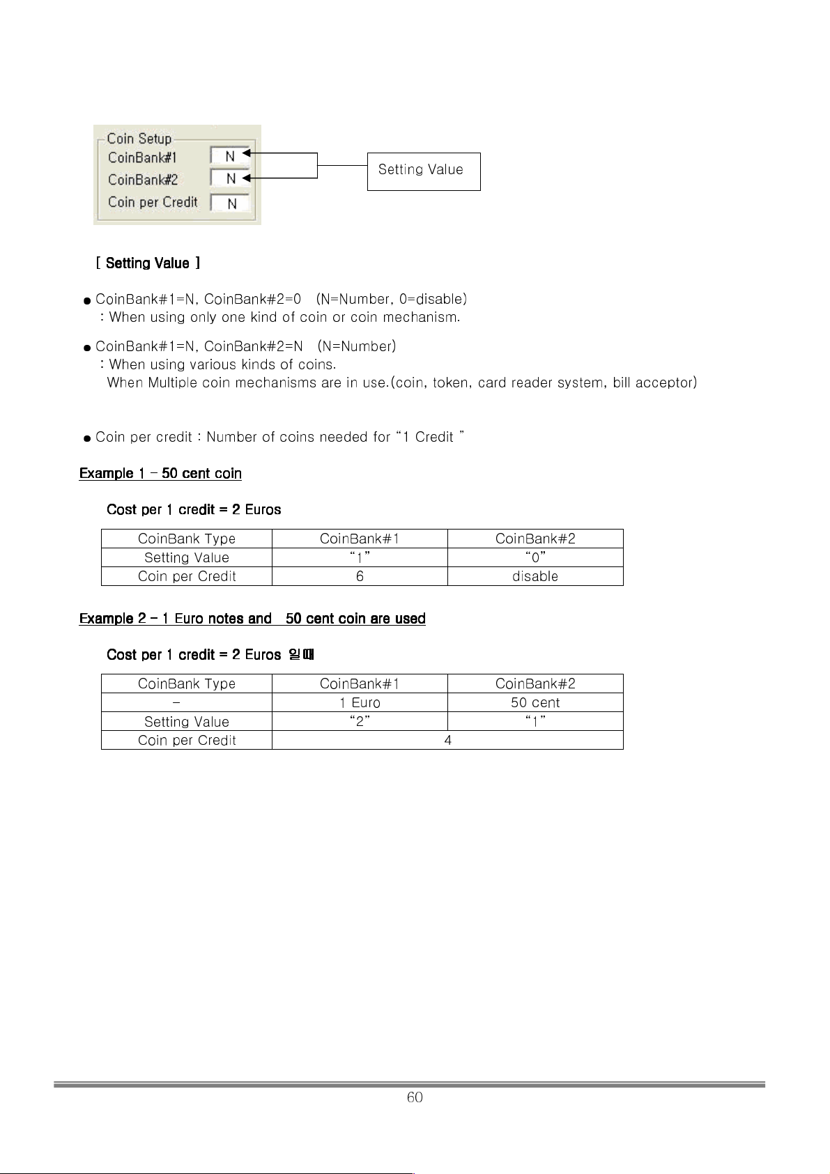
Setting Value
[ Setti
[ Setting Value
[ Setti [ Setti
ng Value ]]]]
ng Value ng Value
●
CoinBank#1=N, CoinBank#2=0 (N=Number, 0=disable)
: When using only one kind of coin or coin mechanism.
●
CoinBank#1=N, CoinBank#2=N (N=Number)
: When using various kinds of coins.
When Multiple coin mechanisms are in use.(coin, token, card reader system, bill acceptor)
●
Coin per credit : Number of coins needed for “1 Credit ”
Example 1
Example 1 –––– 50
Example 1 Example 1
50 cent coin
cent coin
50 50
cent coincent coin
CCCCost per 1 credit = 2 Euros
ost per 1 credit = 2 Euros
ost per 1 credit = 2 Eurosost per 1 credit = 2 Euros
CoinBank Type CoinBank#1 CoinBank#2
Setting Value “1” “0”
Coin per Credit 6 disable
Example 2
Example 2 –––– 1 Eu
Example 2 Example 2
1 Euro
1 Eu 1 Eu
ro notes and
notes and 50
ro ro
notes and notes and
50 cent coin
cent coin are used
50 50
cent coincent coin
are used
are used are used
CCCCost per 1 credit = 2 Euros
ost per 1 credit = 2 Euros 일때
ost per 1 credit = 2 Euros ost per 1 credit = 2 Euros
일때
일때일때
CoinBank Type CoinBank#1 CoinBank#2
- 1 Euro 50 cent
Setting Value “2” “1”
Coin per Credit 4
SIMULINE INC..
60
Page 62
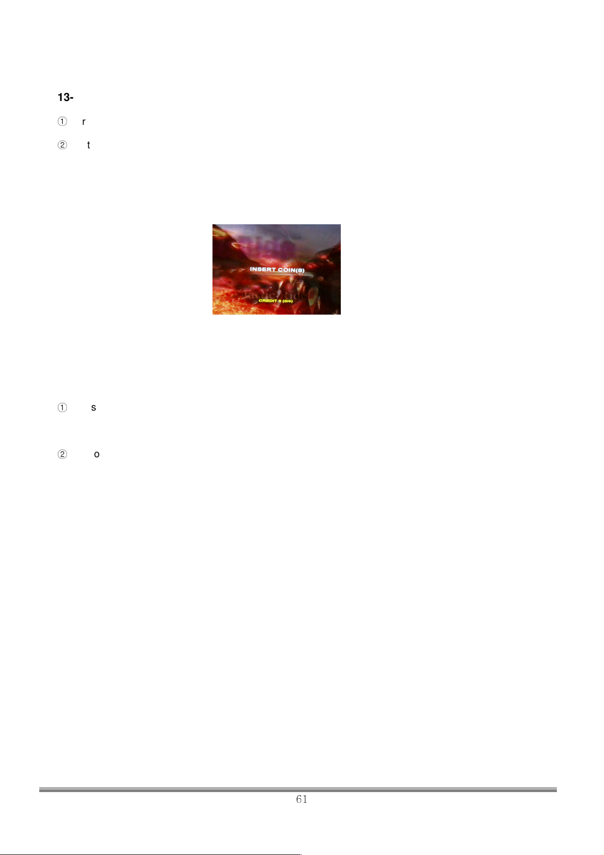
13-2 SYSTEM ON (POWER ON)
①
Turn on the mains input power switch at the rear side of SCU ensuring that 220 single phase power is
connected.
②
System will boot up. In normal case, it will take about 3~4 minutes. The cabin monitor will show boot-up
process and when it finished, control program will be executed. When the system control program executed,
apply the power to the MCU(motion control unit), and then make the cabin move into the initial position.
When the monitor displays attract mode, a start-up process is done and it is ready for a ride.
< Attract Mode>
13-3 System Off (Power OFF)
Powering off should be followed as described in the manual.
①
Press and hold the System Off button for 2 seconds at the rear of the SCU. Pressing this button will make
the cabin move into initial boarding position and then cut the power to the MCU by making the breaker off
sound. Then, the control computer will shut off.
②
Turn off the Mains input switch at the rear of SCU
SIMULINE INC..
61
Page 63
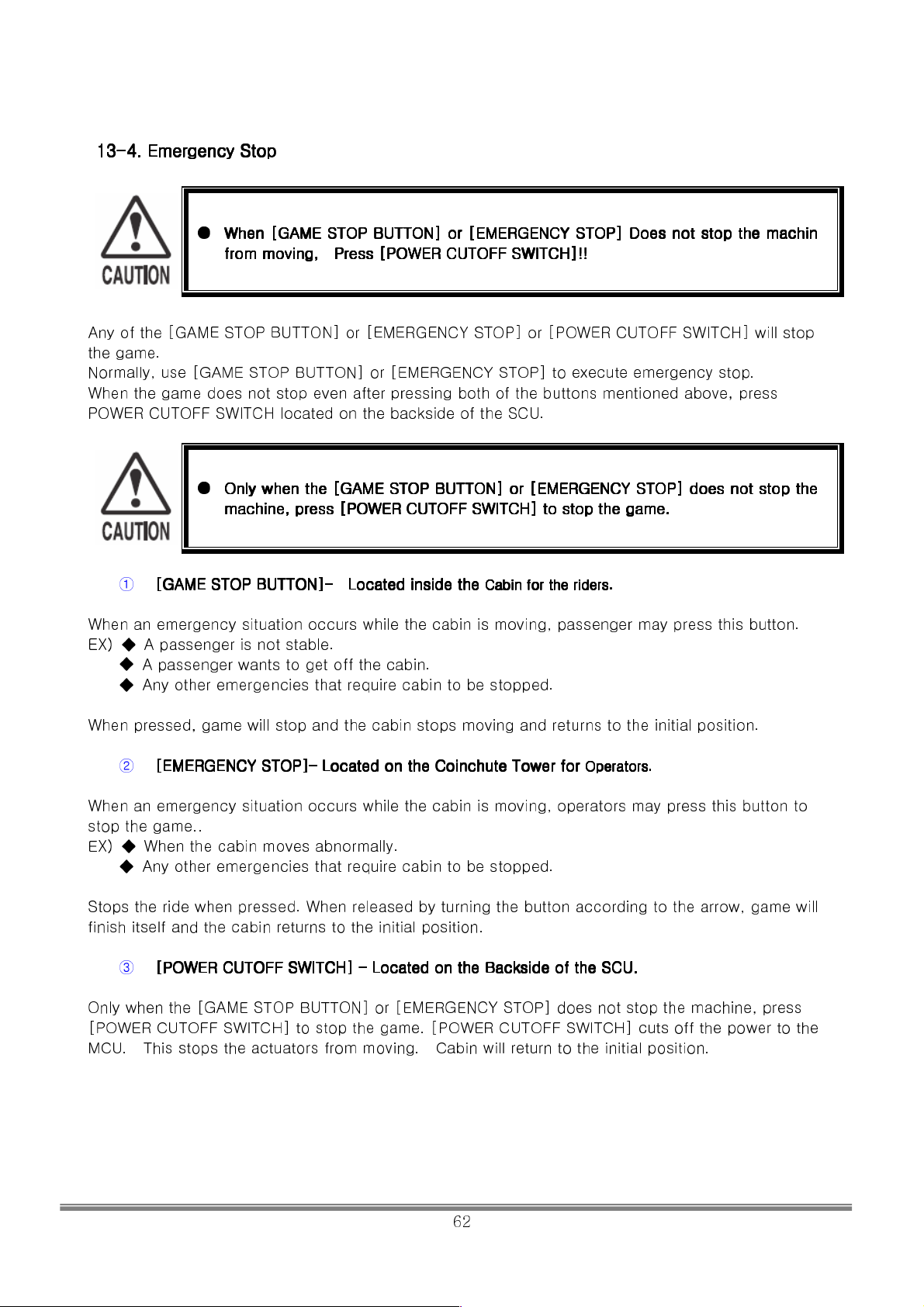
13
13----4444.
. Emergency Stop
1313
Emergency Stop
. .
Emergency StopEmergency Stop
● When
When [GAME
When When
from moving,
from moving, Press
from moving, from moving,
[GAME STOP BUTTON
[GAME[GAME
STOP BUTTON]]]] or
STOP BUTTON STOP BUTTON
Press [[[[POWER CUTOFF
Press Press
POWER CUTOFF SWITCH]
POWER CUTOFFPOWER CUTOFF
or [EMERGENCY STOP]
[EMERGENCY STOP] Does not stop the machin
or or
[EMERGENCY STOP][EMERGENCY STOP]
SWITCH]!!
SWITCH] SWITCH]
Does not stop the machin
Does not stop the machin Does not stop the machin
!!
!!!!
Any of the [GAME STOP BUTTON] or [EMERGENCY STOP] or [POWER CUTOFF SWITCH] will stop
the game.
Normally, use [GAME STOP BUTTON] or [EMERGENCY STOP] to execute emergency stop.
When the game does not stop even after pressing both of the buttons mentioned above, press
POWER CUTOFF SWITCH located on the backside of the SCU.
● Only when the [
Only when the [GAME
Only when the [Only when the [
machine, press
machine, press [[[[POWER CUTOFF
machine, pressmachine, press
① [[[[GAME
GAME STOP BUTTON
STOP BUTTON]]]]–––– Located inside the
GAMEGAME
STOP BUTTON STOP BUTTON
When an emergency situation occurs while the cabin is moving, passenger may press this button.
EX) ◆ A passenger is not stable.
◆ A passenger wants to get off the cabin.
◆ Any other emergencies that require cabin to be stopped.
When pressed, game will stop and the cabin stops moving and returns to the initial position.
② [EMERGENCY STOP]
[EMERGENCY STOP]–––– Located on the Coinchute Tower for
[EMERGENCY STOP][EMERGENCY STOP]
When an emergency situation occurs while the cabin is moving, operators may press this button to
stop the game..
EX) ◆ When the cabin moves abnormally.
◆ Any other emergencies that require cabin to be stopped.
Stops the ride when pressed. When released by turning the button according to the arrow, game will
finish itself and the cabin returns to the initial position.
③
[[[[POWER CUT
POWER CUTOFF
POWER CUTPOWER CUT
Only when the [GAME STOP BUTTON] or [EMERGENCY STOP] does not stop the machine, press
[POWER CUTOFF SWITCH] to stop the game. [POWER CUTOFF SWITCH] cuts off the power to the
MCU. This stops the actuators from moving. Cabin will return to the initial position.
OFF SWITCH]
SWITCH] –––– Located on the Backside of the SCU.
OFFOFF
SWITCH] SWITCH]
GAME STOP BUTTON
STOP BUTTON]]]] or
GAMEGAME
STOP BUTTON STOP BUTTON
POWER CUTOFF SWITCH]
POWER CUTOFFPOWER CUTOFF
Located inside the
Located inside the Located inside the
Located on the Coinchute Tower for
Located on the Coinchute Tower for Located on the Coinchute Tower for
Located on the Backside of the SCU.
Located on the Backside of the SCU. Located on the Backside of the SCU.
or [EMERGENCY STOP]
[EMERGENCY STOP] does not stop the
or or
[EMERGENCY STOP][EMERGENCY STOP]
SWITCH] to stop the game.
SWITCH] SWITCH]
Cabin
Cabin for the riders.
Cabin Cabin
to stop the game.
to stop the game. to stop the game.
for the riders.
for the riders.for the riders.
Operator
Operators.
OperatorOperator
does not stop the
does not stop the does not stop the
s.
s.s.
SIMULINE INC..
62
Page 64
14. MONITOR
14-1. HANDLING CAUTION OF MONITOR
Before handling the monitor, read the following instructions carefully and follow the cautions
below.
Indicates important information
that, if ignored, may result in the
mishandling of the product and
the possibility of personal injury or
death.
Indicates a particular location of
the product that is not to be
touched.
●
Be sure to unplug the power cord first when installing/uninstalling the monitor or
disconnecting any external connector connected to the monitor or the internal
parts of the monitor. Working with the power on may result in electrical shock or
other accidents.
●
Do not modify the monitor without permission. The company is not responsible
for any trouble or accidents caused by unauthorized modifications.
●
Primary side and Secondary side
The monitor circuit is divided into the primary and secondary sides which are
electrically insulated. Do not touch the primary side or both the primary and
secondary sides simultaneously. Doing so may result in electric shock. When
adjusting the device, use a non-conductive screwdriver and do not touch any
other parts except for the handle. Do not short-circuit the primary and secondary
sides. It may cause an electric shock or malfunction.
●
High Voltage
Since the monitor contains parts that generate voltages higher than 20,000 volts,
do not touch the inside. If a piece of metal or paper is falls into the monitor,
immediately turn the power off. Failure to do so may result in a malfunction or a
fire.
14-2. ADJUSTING MONITOR
● Since the monitor is fully adjusted when it is delivered, any other adjustments are
unnecessary. Handling the monitor, which contains high voltage components, is
very dangerous.
In addition, a wrong adjustment may cause breakdown due to a bad screen or
unfixed synchronization.
● Monitor (projector) should be appropriately adjusted. If a defect such as flashing is
detected on the screen, do not leave it without adjustment. An Inappropriately
adjusted screen may cause dizziness, headache, or other physical injury to
customers.
●
● Do not touch any unspecified parts. Failure to comply can result in electric
shock or short-circuit.
Caution
Indicates important information that, if
ignored, may result in the mishandling
of the product and the possibility of
personal injury, and/or may result in
equipment damage.
Indicates that the power connector or
the power plug needs to be
disconnected.
SIMULINE INC..
63
Page 65
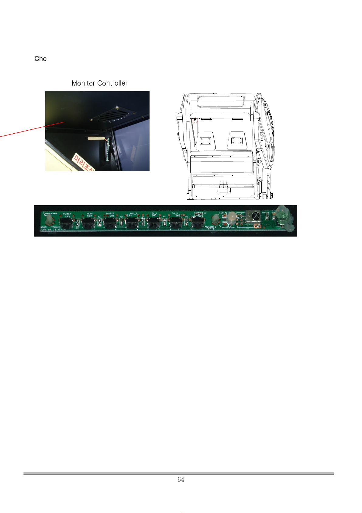
Check the position of the monitor controller. It is located at the left of the monitor.
■ BRIGHTNESS :
■ CONTRAST :
■ SHARPNESS : ADJUST SCREEN SHARPNESS.
■ H-POSITION :
■ V-POSITION :
■ PHASE : ADJUST SCREEN CLOCK PHASE.
■ FREQUENCY : ADJUST SCREEN FREQUENCY.
Monitor Controller
ADJUST SCREEN BRIGHTNESS.
ADJUST SCREEN CONTRAST.
ADJUST HORIZONTAL POSITION.
ADJUST VERTICAL POSITION.
SIMULINE INC..
64
Page 66
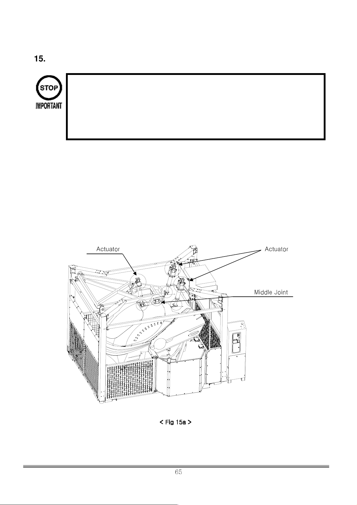
15. Grease Up
• Be sure to use the designated grease. Using undesignated grease can cause
parts damage.
• Do not apply grease to locations other than as specifi ed. Doing so may create
a risk of operational problems and deterioration of parts.
• The designated periods for greasing serve only as a guide. Whenever there are
squeaks or other anomalies, apply grease at designated locations.
Grease UP is required to maintain normal lubricative levels at high/low emperatures and to enchance the
durability of the product.
Neglecting periodic GRASE Ups will shorten the life span of the product and may cause strange noises or
vibrations.
The actuator, Middle Joint of this product must be greased. The product should be greased once in every
year.
- Designated Grease : KLUBER HIMONAX WS433
Use Grease Gun with a flexible Nozzle!
Actuator Actuator
Middle Joint
< Fig 15a >
< Fig 15a >
< Fig 15a >< Fig 15a >
SIMULINE INC..
65
Page 67
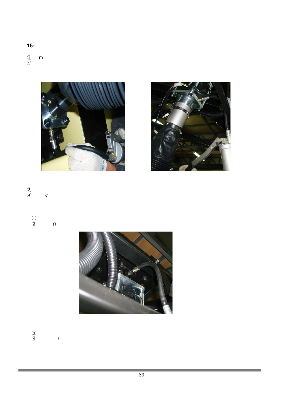
15-1. Actuator Grease Up
①
Remove the bellows of the Actuator
②
Use the Grease Gun to apply 60g to the Grease Nipple of the actuator(TOP), and 30g to the Bottom part.
< Actuator Top > < Actuator Bottom >
③
Wipe off excess grease.
④
Replace the bellows cover into the original positon.
15-2. UNIVERSAL JOINT IN THE ACTUATOR
①
Remove the bellows cover.
②
Apply 5g to the top and bottom of the Universal Joint in the actuator.
< Universal Joint >
③
Wipe off excess grease.
④
Replace the bellows cover into the original position.
SIMULINE INC..
66
Page 68
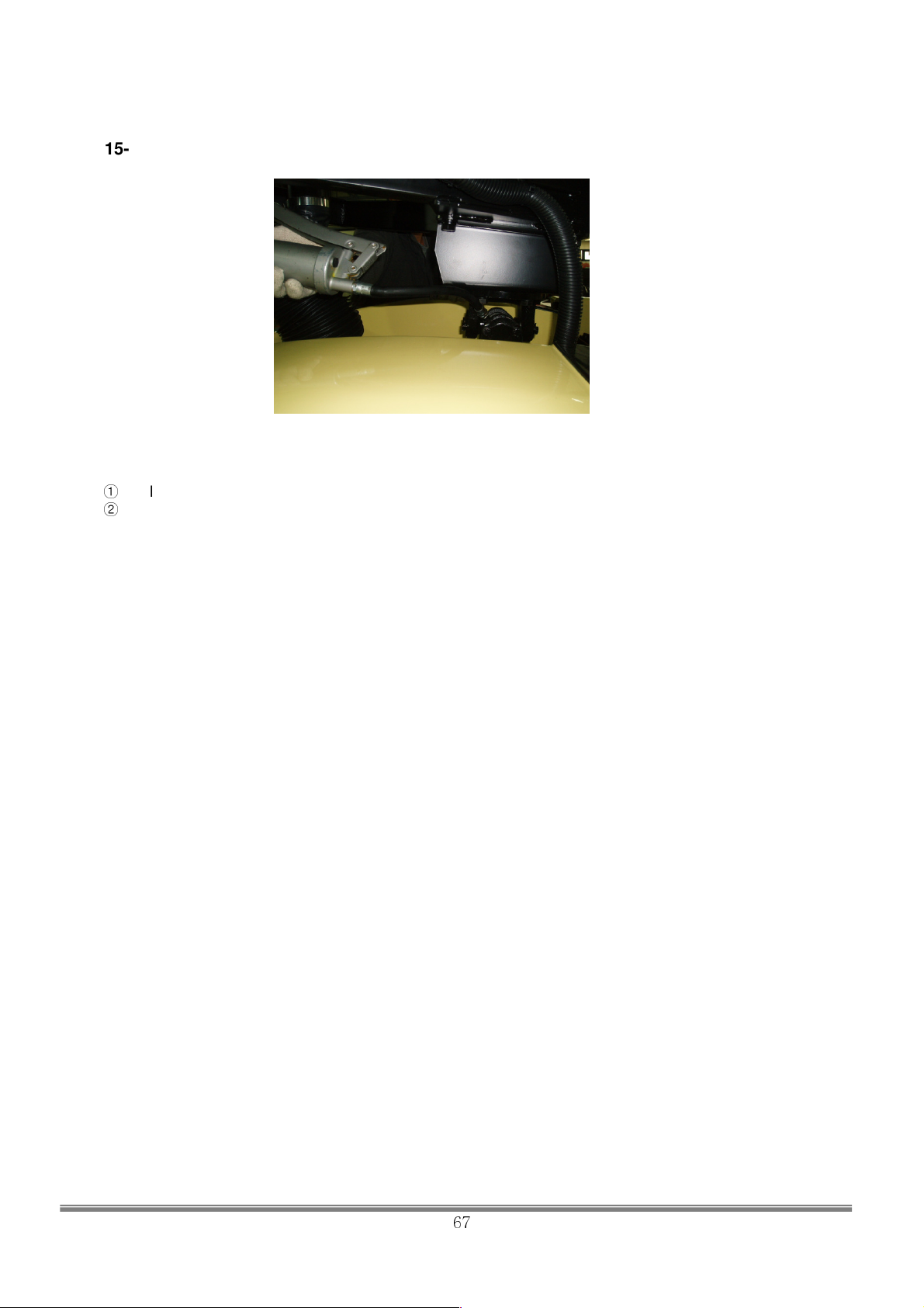
15-3. Grease Up of Middle Joint
①
Apply about 5g of grease to Middle Joint
②
Wipe off excess grease.
< Middle Joint >
SIMULINE INC..
67
Page 69
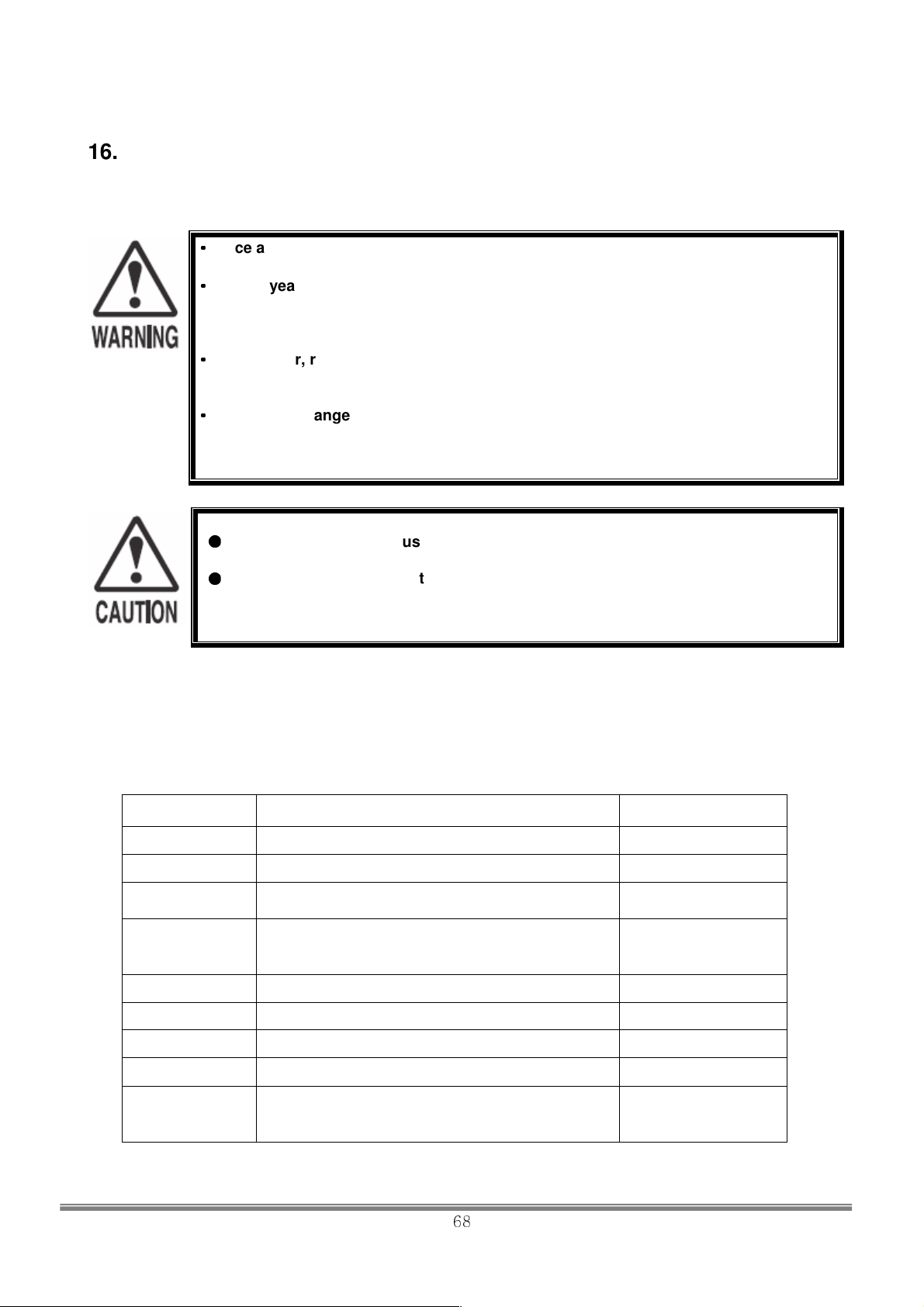
16. Maintenance
16-1. PERIODIC INSPECTION
•
Once a year, check to see if power cords are damaged, the plug is securely
•
••
inserted.
••••
Once a year, request the offi ce shown on this manual or the dealer from whom
the product was originally purchased to perform the internal cleaning. Using the
product with accumulated dust in the interior may cause fi re or other accidents.
Note that you are liable for the cost of cleaning the interior parts.
••••
Once a year, request the offi ce shown in this manual or the dealer from whom
the product was originally purchased to perform routine maintenance on
moving mechanisms. Failure to perform maintenance can lead to accidents.
••••
There is the danger of accidents involving electrical shorts circuits or fi re caused
by factors such as the deterioration of insulation in electrical and electronic
equipment over time. Check that there are no abnormalities such as odors from
burning.
●
Maintenance works must be performed by authorized personnel. Be sure to
follow the instructions in this manual.
●
Maintenance works must be performed after the breaker must be turned off.
Performing works with applied power may result in abrupt operation of the
product or cause electric shock to the body.
In order to maintain the performance of this product and operate it safely, inspect the following items
routinely and perform maintenance.
The player directly touches and manipulates the select button with his/her hands. Clean these buttons as
necessary and provide hand towels, etc., so that players will be comfortable while riding.
PERIODIC INSPECTION TABLE
ITEMS DESCRIPTION PERIOD
Outer frame Confirm that the adjuster is level to the ground Daily
Inside Cabinet Cleaning Daily
Monitor Check screen adjustment
Coin Selector
Electronic parts Inspection As appropriate
Power cables Inspection, cleaning 1 year
Cabinet Cleaning 1 year
Cabin Surface Cleaning As appropriate
Moving
mechanics
Coin insertion test
Coin Selector cleaning
maintenance
Grease up
Monthly or when
moving
Monthly
3 months
1 year
1 year
SIMULINE INC..
68
Page 70
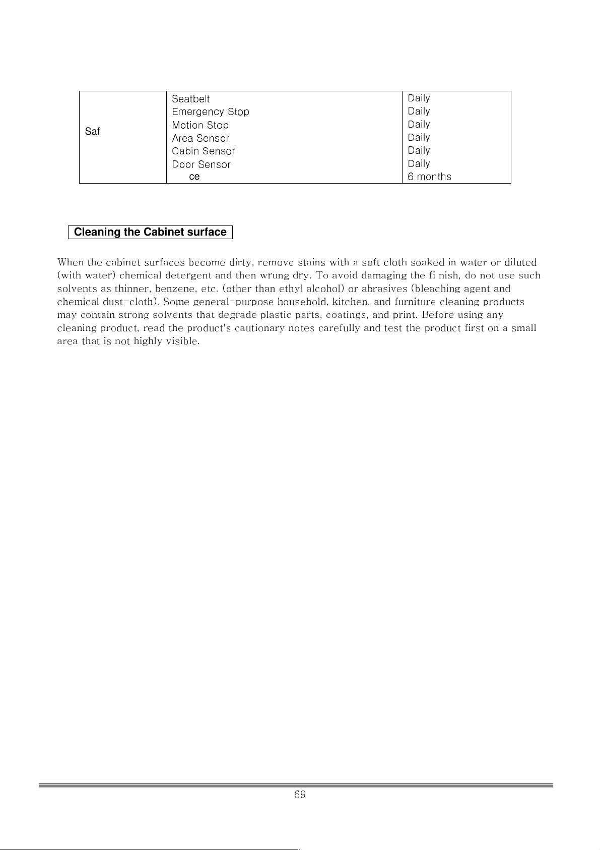
Daily
Daily
Daily
Daily
Daily
Daily
6 months
Safety
equipment
Seatbelt
Emergency Stop
Motion Stop
Area Sensor
Cabin Sensor
Door Sensor
Fence
Cleaning the Cabinet surface
When the cabinet surfaces become dirty, remove stains with a soft cloth soaked in water or diluted
(with water) chemical detergent and then wrung dry. To avoid damaging the fi nish, do not use such
solvents as thinner, benzene, etc. (other than ethyl alcohol) or abrasives (bleaching agent and
chemical dust-cloth). Some general-purpose household, kitchen, and furniture cleaning products
may contain strong solvents that degrade plastic parts, coatings, and print. Before using any
cleaning product, read the product's cautionary notes carefully and test the product first on a small
area that is not highly visible.
SIMULINE INC..
69
Page 71
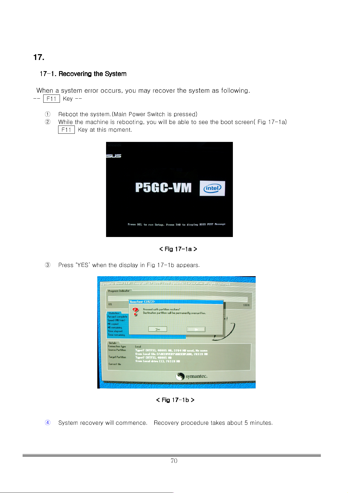
17. Troubleshooting
17
17----1.
1. Recovering the System
1717
When a system error occurs, you may recover the system as
-- F11 Key --
Recovering the System
1. 1.
Recovering the SystemRecovering the System
following.
① Reboot the system.(Main Power Switch is pressed)
② While the machine is rebooting, you will be able to see the boot screen( Fig 17-1a)
F11 Key at this moment.
<<<< Fig 17
Fig 17----1a
Fig 17Fig 17
1a >
>
1a1a
> >
③ Press ‘YES’ when the display in Fig 17-1b appears.
<
< Fig 17
Fig 17----1b
< <
Fig 17Fig 17
④ System recovery will commence. Recovery procedure takes about 5 minutes.
1b >
>
1b1b
> >
SIMULINE INC..
70
Page 72
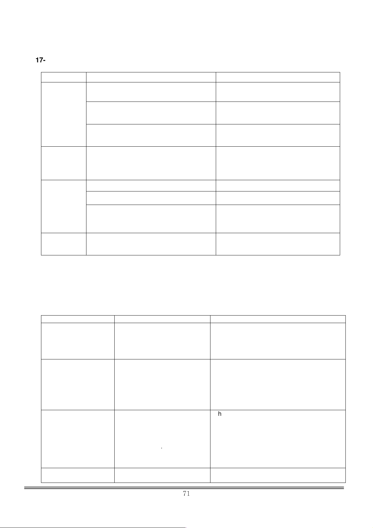
17-2. Troubleshooting table
problems Cause countermeasure
Circuit breaker fo the AC unit is no in operation Connect the AC 220V.
Failure of
power on
System is not
operational
Cabinet does
not operate
Failure to
power off
Plugs are not connected Plug the 220V to the cabinet in outlet.
Mains switch of SCU is off Turn on the mains input switch
Follow the emergency stop sequence by
Check the error message on the cabinet
message
Confirm that the door is closed/ Close the door
Area sensor is interrupted
(YELLOW LED OFF)
Sensor is not alligned Align the sensors
Malfunction of system
turning off the power. Wait for about 1 minute
and switch on again. If it does not work,
contact the service representative listed in this
manual.
Remove the obstacles
(YELLOW LED ON)
Turn off all the powers in the sequence of
Emergency Stop
17-3. MCU Error
Next is a list of Error Codes regarding the Motion Control Board malfunction. Please check the error codes
when an error occurs.
■ MCU Error Message
Error Code Cause Countermeasures
FFOO
FFFF
FFC7
F800
FFFE
Encoder connector at the
Motor Drive Board is
unplugged. (J11)
Motor Drive Board did not
receive signal from encoder
after the power is switched on.
Motor Drive Board (K5,K8)
+12V relay at the input power
is disconnected.
Actuator Limit Sensor is not
responding.
[Check the Encoder Connector]
Check the connection of encoder connector at
the Motor Drive
Board and MCU. Check for any
damages..(J11)
[Check 5V SMPS output]
1.Check to see if the voltage between DGND
and +5V stays
within the range of DC5.0V~5.2V.
2.If 1. checks out OK, and the problem
repeats, contact the
service representative listed in this manual.
Check if the power unit Motor Drive Board
input power SMPS
+12V is normal.
If SMPS +12V power is normal, check the
Motor Drive BD J7
Connector +12V power with a tester. When
the +12V power is
not available, check the connection harness.
1.Check the connection/installation of Actuator
Limit Sensor.
SIMULINE INC..
71
Page 73
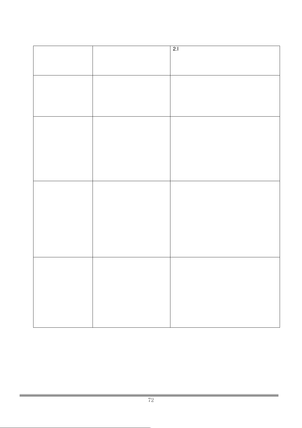
Error at the #1,2,3 Actuators
when the power is supplied.
90AE
9086
8C3 Motor Drive BD IPM Error
10C3
90C3
40C3
DOC3
(Motor Encoder was supplied
with power and the motor
could not fi nd the phase
information. In result, motor
could not find Z pulse.
Over current Protection Error
Overvoltage protection error
2.If 1. checks out OK, and the particular Motor
Drive BD repeats
FFFE Error, contact service representative
listed in this manual
and replace the applied BD.
1.This may happen when the machine was
started in a slanted
position. Restart the system.
2.Actuator Limit Sensor(Bottom Sensor)
installation is not in
order..
1.Check the if AC power to the Motor Drive
BD stays in the
range of AC200V~AC230V.
2.Check the operation of the fan at the Motor
Drive BD
Heatsink.
3. 1,2 checks out and particular motor drive
BD repeats the same
error, contact service representative listed in
this manual and
replace the applied BD.
1.Check to see if the output voltage of the
Main
Transformer(220R,220T) stays within the
range of 210V~230V.
2.Insuffi cient Actuator lubing may cause this
error. Check the
actuator for lubing, and apply lubing when
needed.
3. 1,2 checks out and particular motor drive
BD repeats the same
error, contact service representative listed in
this manual and
replace the applied BD.
1. Check to see if the output voltage of the
Main
Transformer(220R,220T) stays within the
range of 210V~230V.
2.Check the input power source. Check if
there’s a possibility of
temporary voltage over 240V.
3. 1,2 checks out and particular motor drive
BD repeats the same
error, contact service representative listed in
this manual and
replace the applied BD.
SIMULINE INC..
72
 Loading...