

Page 1
INSTRUCTION MANUA
L
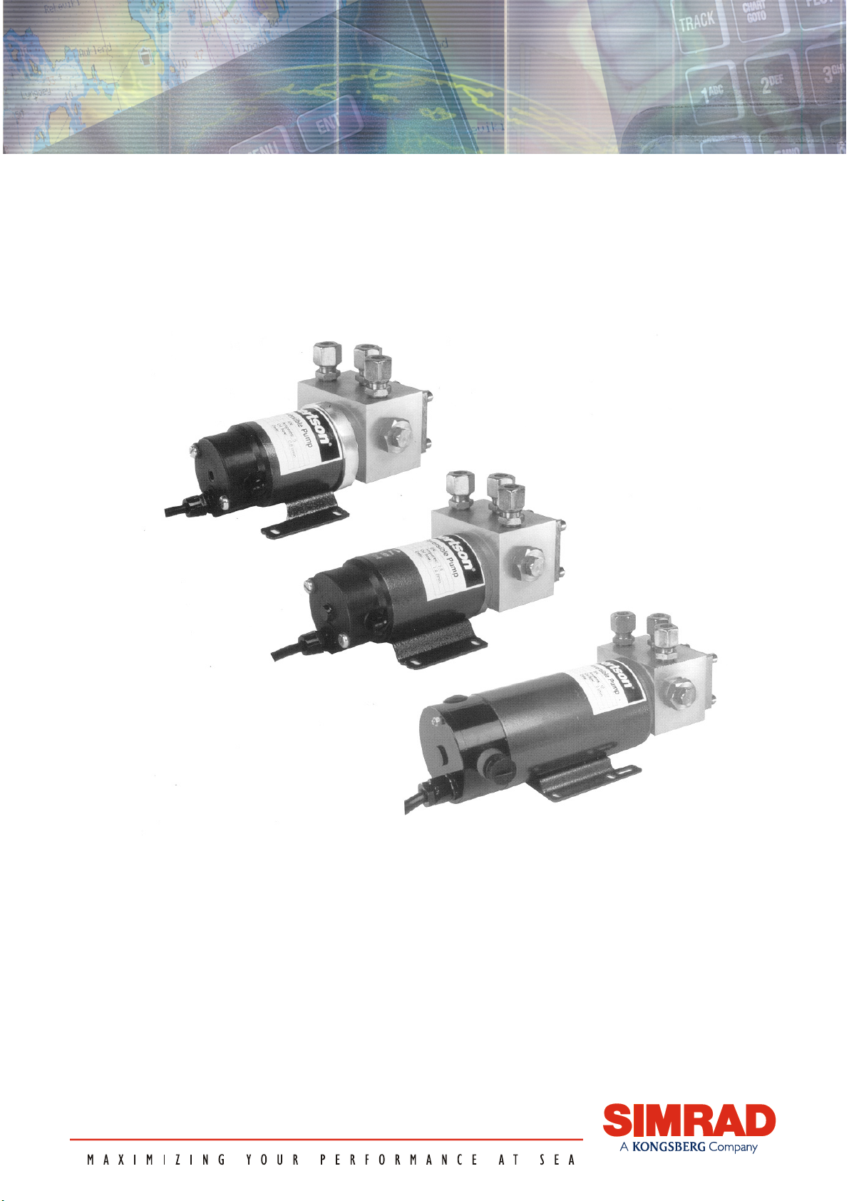
Simrad RPU80/160/300
Reversible Pump
www.Busse-Yachtshop.de email: [email protected]
Page 2

Note!
Simrad AS makes every effort to ensure that the information contained within this
document is correct. However, our equipment is continuously being improved and
updated, so we cannot assume liability for any errors which may occur.
Warning!
The equipment to which this manual applies must only be used for the purpose for which
it was designed. Improper use or maintenance may cause damage to the equipment or
injury to personnel. The user must be familiar with the contents of the appropriate
manuals before attempting to operate or work on the equipment.
Simrad AS disclaims any responsibility for damage or injury caused by improper
installation, use or maintenance of the equipment.
Copyright
© 2004 Simrad AS
The information contained within this document remains the sole property of Simrad AS.
No part of this document may be copied or reproduced in any form or by any means, and
the information contained within is not to be communicated to a third party, without the
prior written consent of Simrad AS.
www.Busse-Yachtshop.de email: [email protected]
Page 3

Instruction Manual
Instruction Manual
This manual is intended as a reference guide for correctly
installing and maintaining the RPU80, RPU160 and
RPU300 reversible pumps.
Please take time to read this manual to get a thorough
understanding of the reversible pump and its relationship to
a complete autopilot system.
Other documentation material that is provided with your
system includes a warranty card. This must be filled out by
the authorized dealer that performed the installation and
mailed in to activate the warranty.
20220422N 1
www.Busse-Yachtshop.de email: [email protected]
Page 4
Simrad Reversible Pump RPU80/160/300
Document revisions
Documentation
department
Hardware/Software
design
Project/Product
Management
Rev Date Sign Date Sign Date Sign
D 24/10-96 N.G. 24/10-96 I.K. 24/10-96 Th.H.
E 20/2-97 N.G. 20/2-97 I.K. 20/2-97 Th.H.
F 5/1-98 N.G. 5/1-98 I.K. 5/1-98 Th.H.
G 20/1-99 N.G. 20/1-99 I.K. 20/1-99 Th.H.
H 21/1-00 N.G. 21/1-00 I.K. 21/1-00 Th.H.
I 17/10-00 N.G. 17/10-00 I.K. 17/10-00 Th.H.
J 30.08.01 N.G. 30.08.01 I.K. 30.08.01 Th.H.
K 22.03.02 N.G. 22.03.02 I.K.
L 15.01.03 N.G. 15.01.03 I.K. 16.01.03 Th.H.
M 28.04.03 N.G. 28.04.03 I.K. 28.04.03 Th.H.
N 11.03.04 N.G 11.03.04 I.K. 11.03.04 Th.H.
Document history
Rev. D Page 1-3: Bosvik steering gear included. Page 3-1 and 3-2: Changes in notes. Page 4-2:
New warning added. Page 7-2: New subparagraph added to paragraph 7.3.
Rev. E Page 3-1 and 3-2: Changes in notes due to modification of RPU80. Page 4-2: Warning
removed. Page 7-1, Paragraph 7.3: Changed text in brackets. Page 8-1: Modified
drawing. Page 9-1 and 9-2: Spare part lists modified due to modification of RPU80.
Rev. F Minor corrections for rudder speed and rudder time in section 1 and 2.
Rev. G New layout. Steering gear table (Paragraph 1.2) revised. New fittings included, pages 17
and 31.
Rev. H Corrected part no. for valve block, page 32. New distributor list.
Rev. I Corrected formula on page 12. Added note on page 17. New distributor list.
Rev. J Added colour for the o-ring at pos. 18, page 33 to avoid mix up.
Rev. K Fig. 9.1. Pos 8. Spring. New part. no. 21100193. Added text and illustrations under
‘Siting’ page 17.
Rev. L Fracmo motors substituted by Lemac motors. All drawings in chapter 8 revised.
Rev. M New part no. on RPU80 Lemac motor, page 34. New distributor list.
Rev. N New paragraph under ‘Fault tracing’ regarding poor brushes. Updated with new
autopilot computers.
2 20220422N
www.Busse-Yachtshop.de email: [email protected]
Page 5

Instruction Manual
Contents
1 INTRODUCTION..................................................................................................5
1.1 General............................................................................................................5
1.2 Hydraulic steering gear suitable for the RPU80/RPU160/RPU300 ...............7
2 MEASUREMENTS AND CALCULATIONS FOR APPLYING THE RPU.12
2.1 Calculation of cylinder volume ....................................................................12
2.2 Minimum rudder time adjustment ................................................................12
3 DESCRIPTION OF RPU80/RPU160/RPU300 .................................................14
3.1 Construction..................................................................................................14
3.2 Principle of operation (ref. figure 3-1 and figure 9-1)..................................15
3.3 Valve block...................................................................................................16
3.4 Gear pump ....................................................................................................16
3.5 Pressure operated non-return (check) valves on outlet A and B ..................16
3.6 Suction valves on outlet C ............................................................................16
3.7 Slide (10) ......................................................................................................16
3.8 Pipe connections ...........................................................................................17
4 INSTALLATION .................................................................................................18
4.1 Mechanical Installation.................................................................................18
4.2 Electrical installation ....................................................................................22
5 PREPARATION AND TESTING ......................................................................23
5.1 Oil filling and bleeding .................................................................................23
5.2 Testing ..........................................................................................................23
6 MAINTENANCE .................................................................................................24
6.1 Dismantling ..................................................................................................24
6.2 Electric motor ...............................................................................................24
6.3 Valve block...................................................................................................24
7 FAULT TRACING ..............................................................................................25
7.1 Pump (motor) is not running/not responding to rudder command ...............25
7.2 The piston rod does not move with rudder commands.................................25
7.3 Excessive noise from the pump unit.............................................................25
7.4 The rudder does not stay in off-midship position, but drifts towards midship
due to water pressure on the rudder .......................................................................26
7.5 Steering wheel is turning while pump unit is operated ................................26
7.6 The piston rod of the rudder cylinder does not move smoothly. ..................26
7.7 Rudder movement stops as water pressure on the rudder increases.............27
20220422N 3
www.Busse-Yachtshop.de email: [email protected]
Page 6

Simrad Reversible Pump RPU80/160/300
7.8 When on automatic steering, the boat swings from side to side without
stabilizing after course changes .............................................................................27
7.9 Small and sudden heading changes while on automatic steering .................27
7.10 Rudder moves only in one direction (with pump running) ..........................28
8 TECHNICAL SPECIFICATIONS ....................................................................29
8.1 Specifications................................................................................................29
8.2 Dimensions ...................................................................................................30
8.3 RPU80 performance .....................................................................................31
8.4 RPU160 performance ...................................................................................32
8.5 RPU300 performance* .................................................................................32
9 SPARE PARTS ....................................................................................................33
9.1 RPU80/RPU160/RPU300.............................................................................33
9.2 RPU80 – Previous model gear pump ...........................................................35
10 SALES AND SERVICE WORLDWIDE 010304..............................................36
4 20220422N
www.Busse-Yachtshop.de email: [email protected]
Page 7

Introduction
1 INTRODUCTION
Note ! This manual does not cover a previous model RPU80 with serial
numbers 101-248. The model is covered by the RPU100
Reversible Pump Manual. Minor modifications where made to
the RPU100 model and they are described in a separate
"Technical Information" no. 01/94.
1.1 General
Hydraulic steering systems are now being used in every
category of small vessel. In many respects hydraulic steering is
preferable to mechanical steering.
Hydraulic systems normally comprise of two main components,
a steering wheel pump and steering cylinder(s). The steering
wheel pump may be either a gear pump or a plunger pump.
Which ever type is installed, steering is achieved by turning the
steering wheel in either direction causing oil from the wheel
pump to be supplied to the appropriate side of the cylinder. Oil
is returned via the opposite side of the cylinder back to the
pump.
The linear motion of the cylinder rod is transformed to a rotary
motion by the tiller, which turns the rudder shaft and rudder.
Check valves (non-return valves) are usually incorporated to
prevent the rudder driving the steering wheel pump.
If an autopilot is to be included in such a hydraulic steering
system, then the oil flow providing the rudder movement must
be controlled by electrical signals from the autopilot.
The maximum flow rate of RPU80, RPU160 and RPU300 is 0,8
l/min., 1,6 l/min. and 3,0 l/min. respectively, measured at a
pressure of 10 bar with nominal voltage (12 VDC) on the motor
terminals.
Note ! RPU300 measurements are based on charging voltage
(14,4VDC)
The flow rate is controlled by the output voltage from the
autopilot's junction unit/computer. When connected to autopilots
using the J300, J3000, all "X"-models of junction units and
ACXX Autopilot Computers, the output voltage that controls the
motor speed is proportional to the heading error from the
autopilot.
This will give slow and smooth rudder movements when
steering on a straight course in calm weather, but will also
ensure fast rudder response for bigger course changes or course
deviations caused by rough sea conditions.
20220422N 5
www.Busse-Yachtshop.de email: [email protected]
Page 8

Simrad Reversible Pump RPU80/160/300
An automatic "Rudder test" function in these autopilots will also
limit the output equivalent to a rudder speed of 8 degrees per
second which is optimum for autopilots with proportional rudder
control. (Equals to approx. 9 seconds for 35-0-35 degrees rudder
travel). Consequently when operating a steering lever or the
Port/Stbd push buttons on the autopilot in manual mode, the
rudder speed will be 8 degrees per second, whilst the rudder
speed when in "Auto" mode normally is less and proportional to
the heading error.
If the pump unit is used with older autopilot models like
AP2500, AP200 or AP45, using J1000B, J101A or J45A
junction units, the output level/flow rate is set by a
potentiometer within the junction unit.
External rudder speed control can be provided by a separate
potentiometer connected to J1000B/J101A/J45A and mounted
near the steering position.
The flow rate must be chosen such that optimum automatic
steering is obtained.
Experience has shown that a rudder time between 10 and 15
seconds hard over to hard over normally gives the best steering
performance. In order to achieve a rudder time within these
limits, the flow rate must correspond with the cylinder volume.
Some boats will perform good automatic steering even with a
hardover time of 20 seconds. The flow-rate, however, is reduced
by increasing load, i.e. increased pressure. It is therefore not
recommended to select a pump with a flow rate that is not able
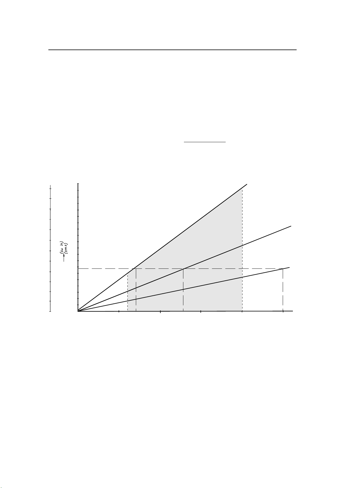
to move the rudder hardover to hardover in 20 seconds as shown
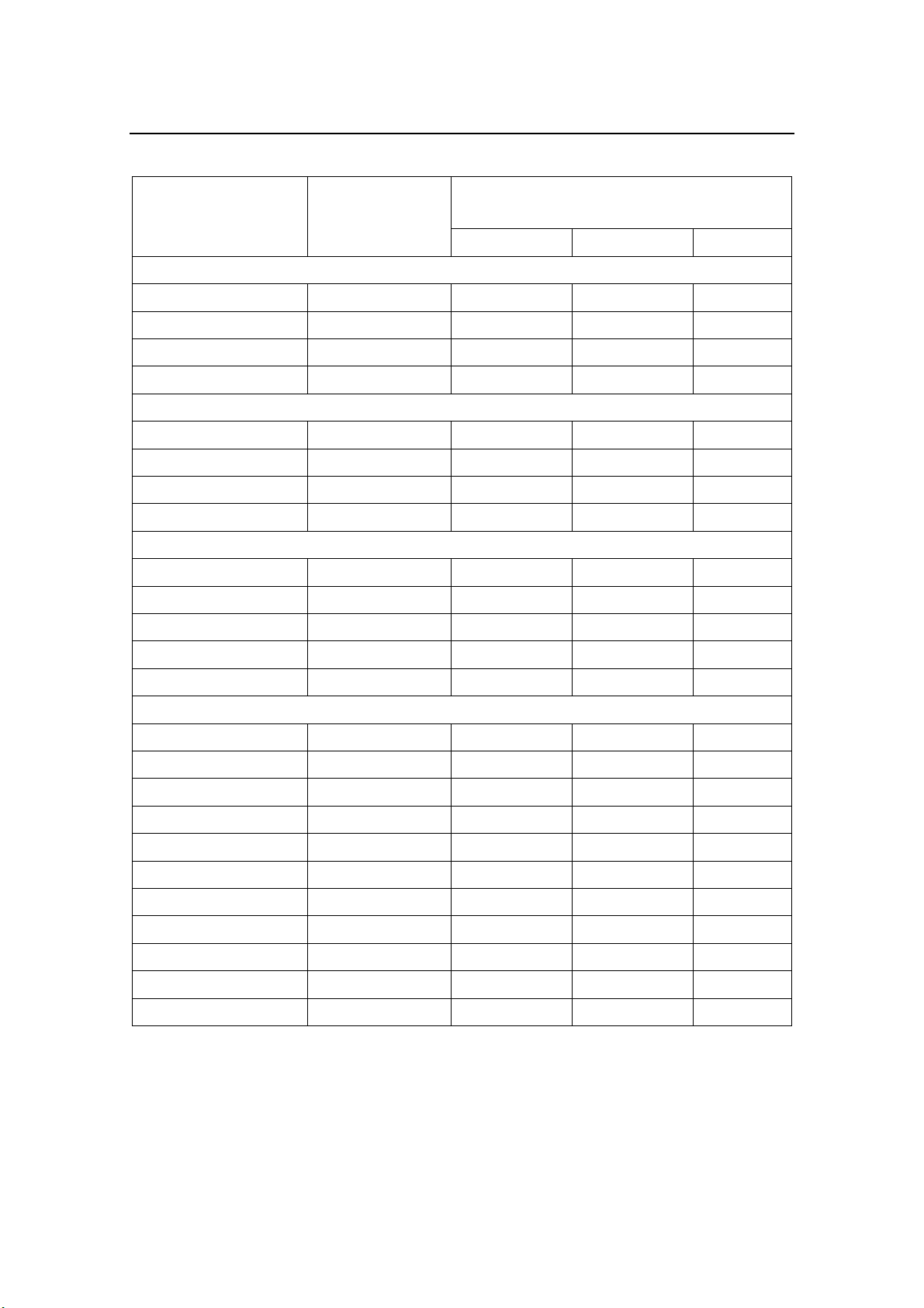
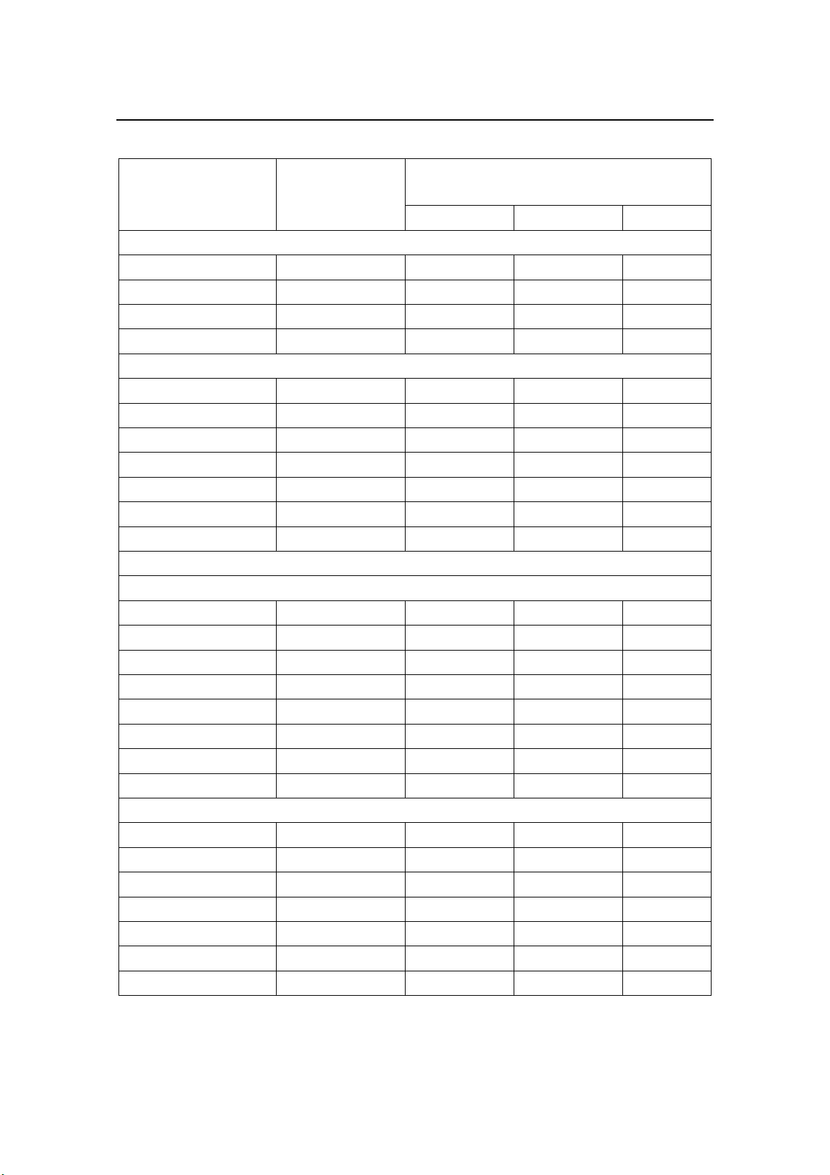
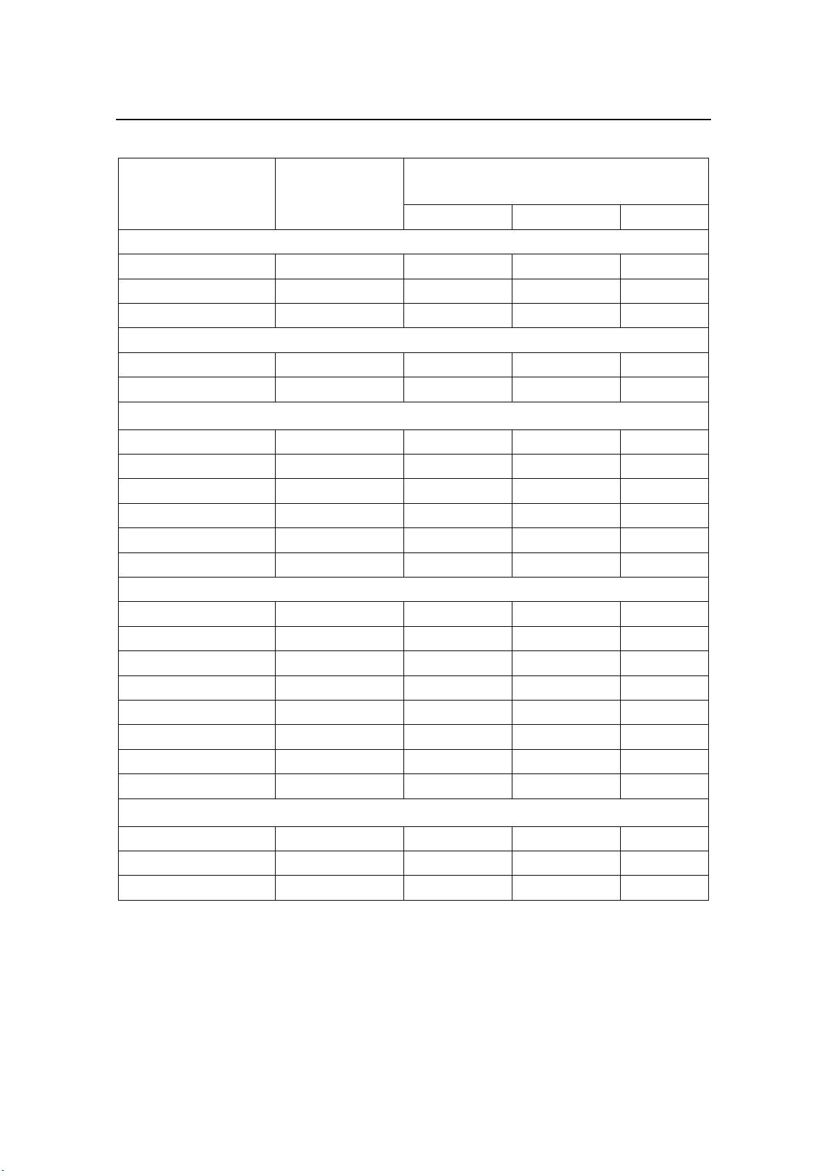
on the nomogram on page 13. Study the tables on the following
pages for appropriate pump selection, and use the nomogram on
page 13 as a guideline.
On page 7 to 11 are listed some well known hydraulic steering
gears together with the corresponding values for the rudder time
hardover to hardover.
The values are calculated from the maximum flow rate at 10 bar
pressure.
If a specific system is not listed, the cylinder volume must be
calculated as explained in section 2.1.
Any well known hydraulic oil with viscosity between 15-70 cSt
at 40°C can be used with RPU80, RPU160 and RPU300.
Use higher viscosity in warmer areas.
6 20220422N
www.Busse-Yachtshop.de email: [email protected]
Page 9
1.2 Hydraulic steering gear suitable for the
RPU80/RPU160/RPU300
All cylinders are single and balanced type unless otherwise
specified. If the cylinder type in your boat is not listed, please
refer to section 2.
Introduction
Steering gear Cylinder
volume cm3
(cu.in.)
BCS (Italian)
MT 25 98 (6,0) 7
MT 35 130 (7,9) 10 5
MT 60 261 (15,9) 20 10 5
MT 120 506 (30,9) 19 10
MT 250 918 (56,0) 18
Bosvik (Norwegian)
EB40 92 (5,6) 7
EB55 124 (56,0) 9
Capilano, Flexatrol (Canadian). See SEASTAR.
Harmek (Norwegian)
Marius 175 95 (5,8) 7
Marius 200 153 (9,3) 11 6
Marius 250 153 (9,3) 11 6
Estimated rudder time in seconds hard
over to hard over
RPU80 RPU160 RPU300
Marius 275 295 (18,0) 22 11 6
Marius 300 700 (42,7) 14
HC (HYDRO-CONTROL) (German)
Regina 50 112 (6,8) 8
Regina 100 172 (10,5) 13 6
HYNAUTIC (USA)
K-1 198 (12,1) 15 7
K-2 288 (17,6) 21 11 6
K-3 378 (23,1) 14 7
K-4 500 (30,5) 19 10
K-7 205 (12,5) 15 8
K-8 642 (39,2) 13
K-10 123 (7,5) 9
20220422N 7
www.Busse-Yachtshop.de email: [email protected]
Page 10
Simrad Reversible Pump RPU80/160/300
Steering gear Cylinder
volume cm3
(cu.in.)
HYNAUTIC (continued)
K-18 115 (7,0) 9
K-19 147 (9,0) 11 6
K-22, K27 218 (13,3) 16 8
K-28, K29 262 (16,0) 20 10
K-31 418 (25,5) 16 8
K-51 167 (10,2) 13 6
Old models
K-25 218 (13,3) 16 8
K-26 262 (16,0) 20 10 5
K-32 327 (20,0) 12 7
K-33 374 (22,8) 14 7
Twin (unbalanced) cylinder
K-5, (x2) 425 (26) 16 9
Estimated rudder time in seconds hard
over to hard over
RPU80 RPU160 RPU300
K-11, K-13 (x2) 360 (22,0) 14 7
K-12, K-14 (x2) 282 (17,2) 21 11
Servo cylinders
PSK-10 108 (6,6) 8 17
PSK-11 225 (13,75) 17 8,5
LECOMBLE & SCHMITT (France)
VHM 228 106 (6,5) 8
VHM 232 138 (8,4) 10 5
VHM 40 DTP 191 (11,7) 14 7
VHM 40-254 239 (14,6) 18 9
VHM 50 DTP 352 (21,5) 13 7
VHM 50-300 464 (28,3) 17 9
VHM 45 228 268 (16,4) 20 10 5
VHM 60 DT 505 (30,8) 19 10
VHM 60-300 664 (40,5) 13
8 20220422N
www.Busse-Yachtshop.de email: [email protected]
Page 11
Introduction
Steering gear Cylinder
volume cm3
(cu.in.)
LECOMBLE & SCHMITT – Old models:
VHM 32-DT 90 (5,5) 7
VHM 35-DTP 152 (9,3) 11 6
VHM 35-DT 129 (7,9) 10 5
VHM 45-DT 240 (14,6) 18 9
SEASTAR
BA 125-7 118 (7,2) 9
BA 150-7 167 (10,2) 13 6
BA175-7 225 (13,7) 17 8
BA 200-7 310 (18,9) 12 6
Twin (unbalanced) cylinder
150-7 TM (x2) 377 (23,0) 14 8
175-7 TM (x2) 508 (31,0) 19 10
200-7 TM (x2) 672 (41,0) 13
Estimated rudder time in seconds hard
over to hard over
RPU80 RPU160 RPU300
175-11 TM (x2) 738 (45,0) 15
200-11 TM (x2) 1000 (61,0) 20
SEIPEM (Italian)
AF230 77 (4,7) 6
CF/CS 230 113 (6,9) 8
CV 51 82 (5,0) 6
CV 76 118 (7,2) 9
CV111 160 (9,8) 12
CM 151 320 (19,5) 12 6
CM 251 440 (26,9) 17 9
CM 351 530 (32,3) 20 11
CM 501 541 (33,0) 20 11
CM 651 706 (43,1) 14
CW 801 1000 (61,0) 20
20220422N 9
www.Busse-Yachtshop.de email: [email protected]
Page 12
Simrad Reversible Pump RPU80/160/300
Steering gear Cylinder
volume cm3
(cu.in.)
SERVI (Norwegian)
MA 60 141 (8,6) 11 5
MA 120 294 (17,9) 22 11 6
MA 200 500 (30,5) 19 10
MA 300 750 (45,8) 15
SLEIPNER, HYDRIVE (Norwegian)
LS 35 90 (5,5) 7
LC 55 129 (7,9) 10 5
LS 60 152 (9,3) 11 6
LC 105 268 (16,4) 20 10 5
LC 155 505 (30,8) 10
LC 250 646 (39,4) 13
LC 330 750 (45,8) 15
TELEFLEX (See SEASTAR)
Estimated rudder time in seconds hard
over to hard over
RPU80 RPU160 RPU300
TENFJORD (Norwegian)
JR 1.10 100 (6,1) 8
JR 1.12 114 (7,0) 9
JR 1.20 210 (12,8) 16 8
JR 1.25 230 (14,0) 17 9
JR 1.30 340 (20,7) 13 7
JR 1.35 375 (22,9) 14 8
JR 1.50 565 (34,5) 21 11
JR 1.60 540 (33,0) 20 11
VETUS (Dutch)
MT 30 67 (4,1) 5
MT 52 104 (6,3) 8
MT 72 146 (8,9) 11 5
MT 105 261 (15,9) 20 10 5
MT 125 253 (15,4) 19 9 5
MT 175 356 (21,7) 13 7
MT 215 532 (32,5) 20 11
10 20220422N
www.Busse-Yachtshop.de email: [email protected]
Page 13
Introduction
Steering gear Cylinder
volume cm3
(cu.in.)
VETUS (continued)
MT 225 500 (30,5) 19 10
MT 340 750 (45,8) 15
MT 450 1000 (61,0) 20
Outboard engine cylinders:
OB 35 106 (6,5) 8
OB 85 170 (10,4) 13 6
Estimated rudder time in seconds hard
over to hard over
RPU80 RPU160 RPU300
Old models:
MT 30 81 (4,9) 6
MT 50 142 (8,7) 11 6
MT 75 195 (11,9) 15 7
MT 100 261 (15,9) 20 10 5
MT 150 530 (32,3) 20 11
B 320 918 (56,0) 18
WAGNER (Canadian)
N40-120 127 (7,8) 10 5
N40-190 200 (12,2) 15 8
N50-190 314 (19,2) 12 6
N50-300 495 (30,0) 19 10
N80-190 802 (48,9) 16
Type 700-1¼ x7 105 (6,4) 8
Type 700-1¼ x9 136 (8,3) 10 5
Type 700-1½ x7 168 (10,3) 13 6
Other types:
20220422N 11
www.Busse-Yachtshop.de email: [email protected]
Page 14

Simrad Reversible Pump RPU80/160/300
π
2 MEASUREMENTS AND CALCULATIONS FOR
APPLYING THE RPU
2.1 Calculation of cylinder volume
The RPU80 is recommended for cylinders between 80-250 cm3
(4,9-15,2 cu. in.), RPU160 for cylinders between 160-550 cm3
(9,8-33,5 cu.in.) and RPU300 for cylinders between 290 -960
cm3 (17,7-58,5 cu.in.). These figures will give for a rudder angle
of 70 degrees (35°-0-35°) a hardover to hardover time of 6-20
seconds equivalent to a rudder speed of 11,6-3,5 deg./second.
Based on experience 6-8 deg./second seems to be the optimum
speed for autopilots with proportional rudder control. However,
a rudder speed between 11,6 deg./second and 3,5 deg./second
should normally cause no problem, particularly not the high
speed which will be reduced by the autopilot electronics.
Depending on type of autopilot the rudder speed is automatically
or manually adjusted during installation and commissioning.
Refer to page 1-1 and the autopilot manual for detailed
information.
The cylinder volume is calculated from the formula:
Volume =
Where
L = stroke length
D = internal cylinder diameter (= outside diameter – 0,6)
d = push rod diameter
π = 3,14
(All dimensions in centimeters)
22
dDL −
)(
4
2.2 Minimum rudder time adjustment
(Applies only for Junction units J1000B, J101A and J45A)
The minimum rudder time can be found as follows (see figure 2-
1):
Draw a horizontal line from the applicable value on the cylinder
volume axis. Rudder time may now be read on the horizontal
axis.
By means of potentiometer RV1 in the Junction unit the rudder
time can be increased.
12 20220422N
www.Busse-Yachtshop.de email: [email protected]
Page 15
Measurements and calculations for applying the RPU
Recommended rudder time: 10-15 seconds is normal for a 70°
(35°-0-35°) rudder angle. (The time will be shorter for smaller
angles and longer for larger angles.) A longer rudder time (20
sec.) should be chosen if the boat has a quick response.
Example:
The stroke length is measured to be 20 cm, D = 5.0 cm and d =
1.8 cm
22
)8,15(20
The cylinder volume is:
−
π
= 340 cm3
4
From the nomogram we find that the estimated rudder time in
seconds, hard over to hard over, will be 7 seconds for RPU300,
13 seconds for RPU160 and 25 seconds for RPU80.
1000
60
900
55
50
800
45
700
40
600
35
500
30
400
25
20
300
15
200
10
100
5
0
(3
0
0
3
U
P
R
0
6
1
U
P
R
(
0
8
U
P
R
)
.
n
i
3
m
/
m
c
0
0
)
.
n
i
3
m
/
m
c
0
0
6
1
(
)
.
n
3
i
m
/
cm
0
0
8
RAM (CYLINDER) CAPA CITY
REVERSIBLE PUMP UNITS RPU80/RPU160/RPU300, CAPACITY NOMOGRAM AT 10 BAR PRESSURE.
RUDDER TIME (SEC.) H.O. TO H.O. FOR A GIVEN CYLINDER VOLUME.
5
67
10 20
2515 SEC.
Figure 2-1
Capacity nomogram for Reversible Pump
RPU80/RPU160/RPU300
Based on the above calculation and the nomogram, the
recommended pump type should be RPU160.
20220422N 13
www.Busse-Yachtshop.de email: [email protected]
Page 16
Simrad Reversible Pump RPU80/160/300
3 DESCRIPTION OF
RPU80/RPU160/RPU300
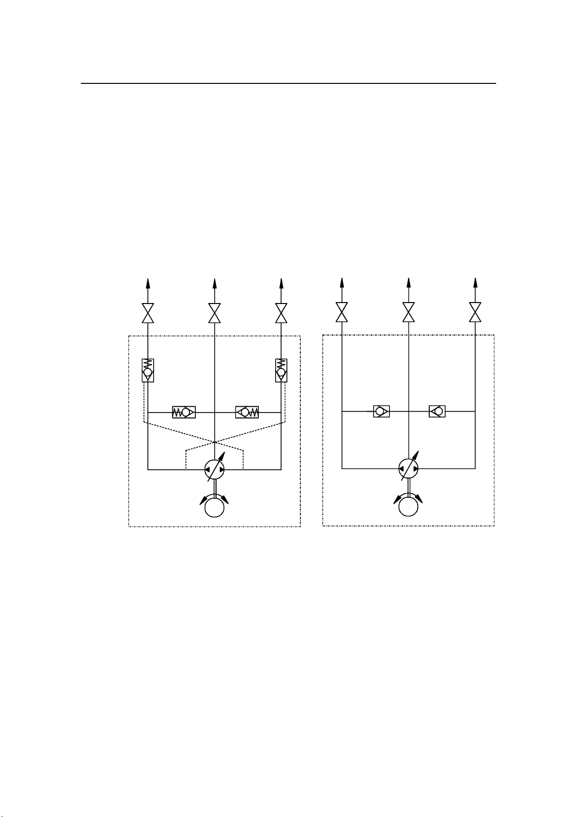
3.1 Construction
The pump comprises an electric permanent magnet motor, valve
block with reversible gear pump, non-return (check) valves on
outlet A and B and suction valves from both sides of the gear
pump to outlet C. Outlet C is connected to either the expansion
tank in the steering wheel pump or a separate expansion tank.
ACB
667
555
44
33
2
M
1
RPU80/RPU160/RPU300 PRINCIPLE DIAGRAM
Principle diagram RPU80/RPU160/RPU300
A
667
55 5
PREVIOUS RPU80 PRINCIPLE DIAGRAM
CB
33
2
M
1
Figure 3-1
1. Electric permanent magnet motor
2. Reversible gear pump
3. Suction valves
4. Pressure operated non-return valves
5. Stop cocks (Not supplied with pump)
6. A+B to main pipes
7. C to expansion tank
The previous model of the RPU80
Reversible Pump was simplified
according to the principle diagram
above. It had no check valves and
there was no spring in the suction
valves.
The simplified units have ser. no.
below 1317 H02 (P/N 21116165)
and 1805 H03 (P/N 21116181-US
version).
14 20220422N
www.Busse-Yachtshop.de email: [email protected]
Page 17

Description of RPU80/RPU160/RPU300
3.2 Principle of operation (ref. figure 3-1 and
figure 9-1)
RPU80/160/300 is reversible: that is the motor changes direction
of rotation and the gear pump delivers oil to that side of the
rudder cylinder dictated by the signal from the autopilot. The
pump runs until the signal from the autopilot ceases. The pump
unit has non-return valves on the outlets A and B. When
running, the pressurized (or delivery) side will hold both nonreturn valves open, using direct oil pressure upon the valve on
the delivery side. This oil pressure is also used to push a slide to
open the valve on the suction side.
When the motor stops, the spring (8) in the non-return valve on
the suction side returns the slide to the neutral position. Both
non-return valves are now closed and the rudder cylinder
locked. Both sides of the gear pump have suction valves to
outlet C.
Note !
If the rudder cylinder is loaded in the same direction as the
rudder command, the slide (10) precisely positions the nonreturn valve (suction side) such that the creation of a vacuum in
the rudder cylinder is prevented. (A vacuum in the rudder
cylinder would result in air being drawn past the seals round the
cylinder piston rod, since these stops the oil pressure only). At
that side of the valve block where the motor is connected, there
is mounted sealing ring (15) and support ring (16) in the valve
block. The support ring causes that the tank connection C can
hold a maximum pressure of 7 bar (Ref. Hynautic steering
systems).
1. A previous model of RPU80 Reversible Pump was simplified
according to the principle diagram. (Ref. figure 3-1 and
figure 9-2). The principle of operation was similar to that of
RPU160. The (suction) valves, however, operated as
combined suction and non-return (check) valves controlled
by internal pressure and direction of oil flow. The resulting
effect was a smoother non-return (check valve) function as
compared to the one with separate non-return valves.
2. It should be observed however, that the previous model of
RPU80 does not have the extra protection against internal
leakage (bypass) as the other models with separate check
valves.
20220422N 15
www.Busse-Yachtshop.de email: [email protected]
Page 18

Simrad Reversible Pump RPU80/160/300
3.3 Valve block
This is an aluminum block with borings for non-return valves,
suction valves, slide, gear pump, motor coupling and all
necessary oil ways. The three outlets A, B and C are positioned
on top of the valve block.
3.4 Gear pump
This comprises of the driving gear wheel, which is coupled to
the motor shaft via a flexible shaft coupling, and meshed with
the driven gear wheel supported by the valve block (1) at one
end and by the pump cover (5) at the other.
The gear wheels run in the pump housing. The gear wheels are
1/100-2/100 mm smaller than the pump housing.
O-rings are fitted to both the valve block and the pump cover to
provide oil tight seals on both sides of the pump housing.
The pump cover is held by 4 screws (25).
When the gear wheels rotate, oil is carried in the inter-tooth
spaces around the periphery of the pump housing from the
suction side to the pressure side.
3.5 Pressure operated non-return (check) valves
on outlet A and B
These are screwed into the valve block from both sides. The
valve comprise of valve housing (6), plug (7), ball (12), spring
(8), copper washer (17), O-ring (13) and copper washer (14).
The housing and plug are made of stainless steel.
3.6 Suction valves on outlet C
These are connected to both sides of the gear pump via oil ways
in the valve block. The valve comprises of a grub screw (21),
spring (9) and ball (20).
If the grub screw (21) is removed, it should be refitted with
Loctite 542 after degreasing the threads.
3.7 Slide (10)
This is located within the valve block in a cylindrical run
between the non-return valves for outlets A and B. The slide is
grooved to allow location of an O-ring (13).
16 20220422N
www.Busse-Yachtshop.de email: [email protected]
Page 19

3.8 Pipe connections
The 3 outlets have fittings for 3/8" (US model) or 10 mm (EU
model) outer diameter pipe. The two outer outlets A and B
connect to the main pipes. The middle outlet C connects to the
bottom of the expansion tank in the steering wheel pump or a
separate expansion tank.
Description of RPU80/RPU160/RPU300
20220422N 17
www.Busse-Yachtshop.de email: [email protected]
Page 20
Simrad Reversible Pump RPU80/160/300
4 INSTALLATION
4.1 Mechanical Installation
Siting
The pump unit should be sited where it is most practical
between rudder cylinder and helm pump, however, it should not
be mounted in a wet area. If the pump unit is sited higher than
the rudder cylinder, air bubbles in the oil coming from the
rudder cylinder could pass through the pump unit on the way to
the expansion tank in the steering wheel pump. This will disturb
the oil flow as the air bubbles pass through.
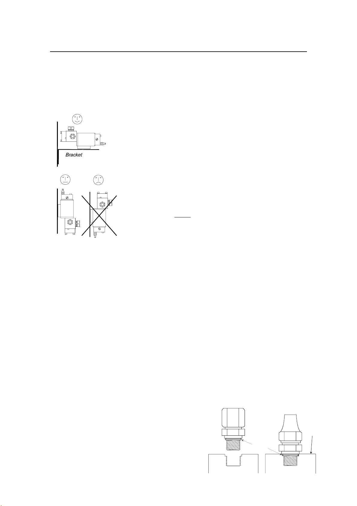
The pump unit should be mounted horizontally, with the pipe
connections/fittings pointing upwards. Use a 90° bracket if
mounted on a bulkhead. It could however be mounted directly
on a bulkhead, but never with the motor pointing downwards, as
oil leak/sweating from a poor shaft seal can easily penetrate the
motor and destroy it.
Fittings
For pump units manufactured before January 1999, the fittings
are factory mounted on the pump housing.
From January 1999 a different type of fitting is used. The new
fitting has an O-ring seal between the fitting and the pump
housing.
The threads are changed from ¼” NPT to 7/16”-20 UNF both on
the European and the U.S. version. The pipe connection remains
the same as before.
Note ! Because the threads are different the new fittings cannot be used
with an old pump and vice versa.
The fittings are easily inserted and less critical with regard to
tightening torque. Consequently the fittings need not be
mounted at the factory. They are now supplied with the pumps
in a plastic bag for mounting during pump installation.
Protection caps cover the threads in the pump housing during
transportation.
Note ! As these fittings have o-
ring sealing there is no
need for additional
sealing compound.
Use following procedure
when mounting the
fittings on the pump;
European
type
fitting
O-ring
US type
fitting
Pump
housing
18 20220422N
www.Busse-Yachtshop.de email: [email protected]
Page 21
Installation
• Use the fingers and turn clockwise until a noticeable
increase in torque is required.
• Tighten further by 30 degrees (= 1/12 of a turn) using
necessary force (25-30 Nm/230-260 In.Ibs).
Pumps with new fittings have got new serial no. code and is
valid from the following s.no’s; RPU80: s.n. 2460 H06,
RPU160: s.n. 1560 H14, RPU300: s.n. 380 H28, RPU300, 24V:
s.n. 180 H29
Installation of pipes
Drain the oil from the steering gear by loosening the rudder
cylinder couplings. At a convenient point cut the pipes and
mount a T-coupling to each pipe. Cutting ring couplings of an
appropriate diameter should be used. Ensure that the pipe is cut
at a right angle as otherwise the ultimate tightness of the
coupling may be adversely affected. It is preferable to use pipe
cutting tool for this operation.
Note ! It is very important to remove ALL traces of metal filings and
other impurities from the pipes after cutting.
Figure 4-1 Figure 4-2 Figure 4-3
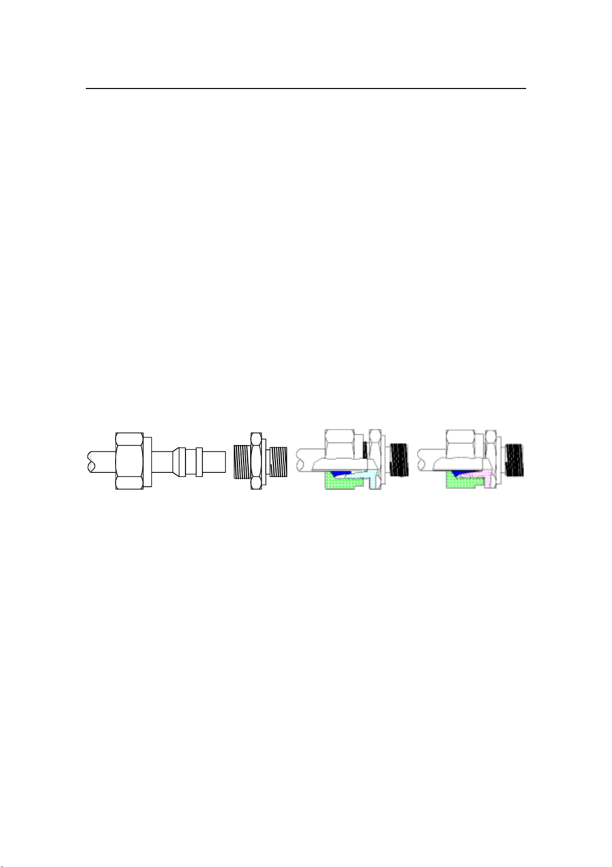
Figure 4-1, 4-2 and 4-3 show the parts that form a cutting ring
coupling. It is important to note which way the cutting ring is
fitted, the following procedure should be followed:
a) Nut and cutting ring are slid over the pipe, figure 4-1.
b) A few drops of oil are first applied to the threads of the
coupling. The pipe is then inserted fully into the coupling and
held whilst the nut is tightened by hand until the cutting ring
rests against the cone (figure 4-2).
c) The nut is now tightened 1½ - 2 turns until the cutting ring
cuts into the pipe surface (figure 4-3). Ensure that the pipe is
held firmly in place whilst the nut is tightened. Release the
coupling and check that the cutting ring has successfully cut
into the pipe.
20220422N 19
www.Busse-Yachtshop.de email: [email protected]
Page 22
Simrad Reversible Pump RPU80/160/300
A clearly formed lip should be visible on the pipe in front of the
cutting ring. If this is not present, the nut should be tightened by
an additional ½ - 1 turn. Check once again as above. From the
T-couplings run a pipe 10x1 mm (US model: 3/8"), to the pump
unit. Avoid high points in the run that could allow air pockets to
form.
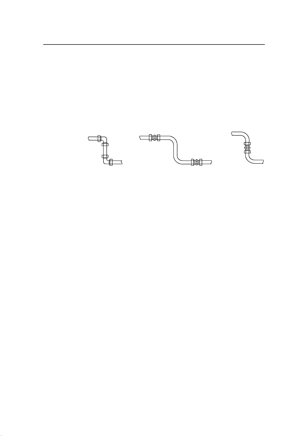
Sharp bends in the pipes (i.e. elbow bends) should be avoided as
these restrict the oil flow. For the same reason couplings should
not be fitted on bends, see Figure 4-4.
Pipes should be bent cold. Attempts to use blowtorch and sand
will lead to impurities entering the system, and should therefore
be avoided.
Figure 4-4
Stop cocks should be fitted to all pipes near the pump unit.
Sluice cocks or similar should be used, and not cocks of the
water supply type. Pipes should be fitted from the stopcocks to
the outlet A and B of the pump unit.
Connection to expansion tank
Most hydraulic steering gears have an expansion tank
incorporated in the steering wheel pump. At the bottom of this
tank is a drain plug, which should be removed and replaced by a
coupling which fits the expansion pipe (10x1 mm, US model:
3/8").Fit a 10x1 mm (US model: 3/8") pipe from the wheel
pump at a uniform, gradual, downward slope to the pump unit.
A stop cock should also be inserted in this pipe near the pump
unit.
Connection to separate expansion tank
If the steering wheel pump does not incorporate expansion tank,
a separate expansion tank must be installed. This tank should
have a volume of 1/4 liter (0.25 qt), and be placed at
approximately the same level as the steering wheel pump.
Lock valve for steering wheel pump
If the steering wheel pump is not provided with a lock valve
(they most often are), an adequate lock valve should be fitted.
20 20220422N
www.Busse-Yachtshop.de email: [email protected]
Page 23
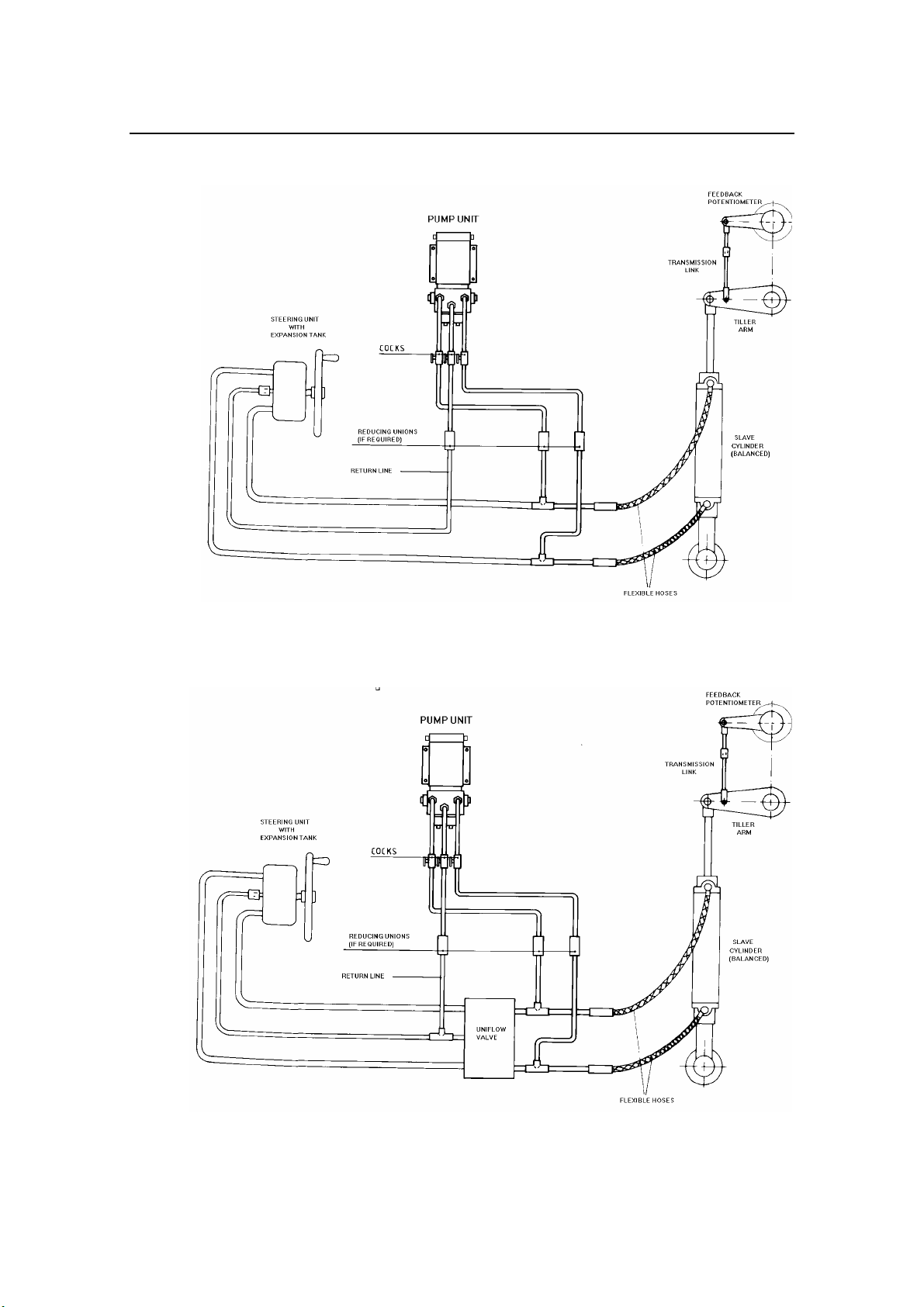
Installation
Figure 4-5
Connection to hand hydraulic steering gear
Drw.no. 3-110101
Figure 4-6
Connection to Capilano steering gear
Drw.no. 3-110115
20220422N 21
www.Busse-Yachtshop.de email: [email protected]
Page 24

Simrad Reversible Pump RPU80/160/300
4.2 Electrical installation
J3000X, J300X, J300X-40, J50, J50-40, AC10, AC20, AC40
The two leads from the motor are connected to the terminal
block marked "MOTOR" in the Junction unit/Autopilot
computer. There is no dedicated Port and Stbd output. The
autopilot will automatically set the correct direction during
"Rudder Test".
Refer to Autopilot manual for further details.
J1000B, J101A and J45A
The two leads from the motor are connected to the terminal
block in the Junction unit marked Motor A and B. Interchanging
of the two leads will change the rotary direction of the motor
(see paragraph 5.2).
The Reversible Pump units are operated from 12V DC via the
Junction unit. This 12V output can be reduced by internal trim
potentiometer (RV1) to reduce rudder speed (see paragraph 2.2).
22 20220422N
www.Busse-Yachtshop.de email: [email protected]
Page 25

5 PREPARATION AND TESTING
5.1 Oil filling and bleeding
When installing a pump unit, it is recommended that the whole
system be emptied and refilled. Use a well known oil of a
viscosity meeting the specification of the steering gear
manufacturer.
Start by opening all stop cocks in the pipes leading to the pump
unit. Simultaneously fill the steering wheel pump with oil whilst
turning the wheel itself, back and forth. Proceed by opening the
couplings at the rudder cylinder whilst still turning the wheel,
this will assist in creating pressure within the system, continue
until clean oil is seen at the couplings. Now tighten the
couplings. Then open the 3 couplings on outlet A, B and C on
top of the pump unit, and repeat the same procedure.
Installation
5.2 Testing
Set the autopilot to manual mode and use a remote control or the
Port/Stbd buttons on the control unit to run the rudder hard over
to hard over to check the operation of the system. Check that the
rudder goes to the same side as the signal you are giving by the
remote control. If not, interchange motor cable connections A
and B in the junction unit (J1000B, J101A, J45A). If necessary
top-up the expansion tank. Repeat the bleeding procedure
(paragraph 5.1) after the equipment has been used for about 5-10
hours.
In the X-series Autopilots (AP300X, AP35, AP20, AP21, AP22)
and the AP16, AP25, AP26, AP27 and AP50 autopilots,
checking motor rotation or interchange of cables in the junction
unit/autopilot computer is not necessary, because the autopilot
will determine the correct rotation automatically during the
"rudder test".
20220422N 23
www.Busse-Yachtshop.de email: [email protected]
Page 26

Simrad Reversible Pump RPU80/160/300
6 MAINTENANCE
6.1 Dismantling
After approximately 1000 operating hours, the pump unit should
be removed for examination.
Close the stop cocks to the pump unit, remove the nuts on the 3
couplings and all retaining nuts.
Screw out the 2 fixing screws (24) located on each side of the
pump cover which hold the valve block and motor together. (See
figure 9-1).
6.2 Electric motor
Examine the brushes for wear and replace if required.
6.3 Valve block
Examine the oil seal (15) for wear and replace if required.
24 20220422N
www.Busse-Yachtshop.de email: [email protected]
Page 27

Fault tracing
7 FAULT TRACING
If fault develops, the source and location must be traced. Close
all stop cocks to the pump unit and check whether the steering
gear functions normally using only the steering wheel pump. If
so, then the fault is most probably in the pump unit or junction
unit/autopilot computer.
The following faults may be tested for:
7.1 Pump (motor) is not running/not responding
to rudder command
Probable reason:
Brushes sticking or worn out. Remove the brushes and check.
Sticking brushes should be wiped clean and any carbon dust
should be removed from the brush holders. Check that the
brushes move without restraint before they are secured.
7.2 The piston rod does not move with rudder
commands
Probable reason:
1. Check that the stop cocks are open.
2. The pump is sucking air. Check outlets A, B and C for
leakage. If the fault is not found here, check the non-return
valves for leakage, especially the copper gaskets between the
end plug and the valve housing.
Leakage may also occur in the threads of the suction valves
grub screws (21). Check both. If leakage is present, the
pump unit has to be dismantled. See paragraph 7.10 for
dismantle and cleaning of the suction valves.
3. See also paragraph 7.10.
7.3 Excessive noise from the pump unit
Probable reason:
1. Air in outlet C to expansion tank. Ensure that the stop cocks
are open, if so, loosen the nut on the coupling and check that
the oil is flowing normally.
20220422N 25
www.Busse-Yachtshop.de email: [email protected]
Page 28

Simrad Reversible Pump RPU80/160/300
7.4 The rudder does not stay in off-midship
position, but drifts towards midship due to water
pressure on the rudder
Probable reason (Does not apply for the previous model of
RPU80):
1. The non-return valves are leaking. Shut the stop cocks to the
pump unit, and operate the steering gear by means of the
steering wheel pump. If the steering is normal by hand
operation, the fault must be in the non-return valves or the
slide.
If the slide is locked because of oil contamination, the nonreturn valve may be held open.
If the fault is not found on the slide, both of the non-return
valves have to be disassembled. Check the ball seat in the
valve housing for wear etc. Replace the O-ring and copper
gaskets. After having assembled the ball, spring, gasket and
plug, check that the spring pressure on the ball is sufficient
to keep the ball seated. The spring needs a certain preloading to bring the slide back to neutral position.
2. If the problem appears on an RPU80 installation, the reason
may be oil contamination or worn ball seals in the suction
valves. Remove the steel balls for inspection and check the
seals for possible wear. Refer to paragraph 7.10.
3. If the steering gear does not function normally by hand with
the pump unit isolated from the system, there must be a fault
in the steering gear. In order to trace a fault of this nature,
use the instructions given by the manufacturer of the steering
gear.
7.5 Steering wheel is turning while pump unit is
operated
Probable reason:
1. Leaking lock valve in the wheel pump. Check as described
under paragraph 7.4.2.
2. Lock valves are not fitted. Attach lock valve.
7.6 The piston rod of the rudder cylinder does not
move smoothly.
Probable reason:
1. Air in the steering system. Repeat bleeding procedure
described under paragraph 5.1. Look for leakage.
26 20220422N
www.Busse-Yachtshop.de email: [email protected]
Page 29

Fault tracing
7.7 Rudder movement stops as water pressure on
the rudder increases.
(J1000B, J101A, J45A only)
Probable reasons:
1. Overload. Check whether the r.p.m. of the motor is too low.
Eventually turn potentiometer RV1 in junction unit
clockwise (CW) until rudder movement is recovered.
7.8 When on automatic steering, the boat swings
from side to side without stabilizing after course
changes
(J1000B, J101A, J45A only)
Probable reasons:
1. The rudder movement is too slow. Correct as in paragraph
7.7
2. Wrong setting of the autopilot. Refer to the set-up procedure
for the autopilot.
7.9 Small and sudden heading changes while on
automatic steering
(J1000B, J101A, J45A only)
Probable reasons:
1. The rudder movement is too fast. Turn potentiometer RV1 in
junction unit counter-clockwise (CCW) until optimum
rudder speed is achieved.
2. Refer to paragraph 7.8.2.
20220422N 27
www.Busse-Yachtshop.de email: [email protected]
Page 30

Simrad Reversible Pump RPU80/160/300
7.10 Rudder moves only in one direction (with
pump running)
Probable reason:
Suction valve not working (pos. 20, 9, 21) on one side. This is
most probably caused by metal fragments that have entered into
the suction valve(s) through the tube fitting for the return line
(C) during installation. Ref. figure 3-1.
The suction valve (3) on the side that is not giving pressure must
be opened and thoroughly cleaned, and for safety reasons the
other valve should also be inspected and cleaned before
reinstalling the pump unit.
For disassembling and cleaning of the suction valves please use
following procedure (Ref. figure 9-1):
1. Unscrew the grub screw - pos. 21.
2. Remove the spring - pos. 9, and the steel ball - pos. 20.
3. Thoroughly clean the valve seat and the threads in the valve
block (1). Also clean the removed steel ball (20), spring (9)
and grub screw (21). Use Loctite "Super Clean" or similar.
Reassemble as follows:
1. Put the steel ball (20) into the valve block.
2. Put the spring (9) onto the grub screw (21) before it is
screwed into the valve block.
Note ! Use Loctite 542 or similar on the threads to prevent oil leakage.
If Loctite 747 "Activator" is sprayed on the threads before
applying Loctite 542, this will speed up the hardening
process.(With Loctite 542 only, you have to wait 4 hours before
the pump unit can be put in operation again. Using Loctite
"Activator" reduces the hardening time to 1 hour).
3. Make sure the grub screw (21) is screwed in until it is flush
with the valve block (1). This will ensure correct spring
tension in the suction valve.
28 20220422N
www.Busse-Yachtshop.de email: [email protected]
Page 31
Technical Specifications
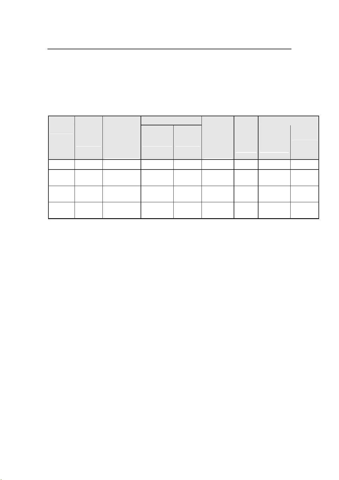
8 TECHNICAL SPECIFICATIONS
8.1 Specifications
Note ! RPU300 measurements at charging voltage
RAM CAPACITY
MODEL MOTOR
VOLTS
*
RPU80 12 V J3000X/AC10 80 (4,9) 250 (15,2) 800 (49) 60 2,4-6 A <35 ft
JUNCTION
UNIT/
AUTOPILOT
COMPUTER
**
MIN
3
cm
(cu. in.)
MAX
3
cm
(cu. in.)
FLOW
RATE AT
10 bar
cm3/min
(cu.in/min)
MAX
PRES-
SURE
bar
PWR.
CONSUM-
PTION
***
BOAT
LENGTH
RPU160 12 V J300X/AC20 160
(9,8)
RPU300 12 V J300X-40/
AC40
RPU300 24 V J300X/AC20 290
290
(17,7)
(17,7)
* The motor voltage is transformed by the junction unit/autopilot
computer when operating from 24V or 32V mains.
** The specified junction unit/autopilot computer is
necessary to achieve max. drive unit capacity.
*** Typical average 40% of max. value.
550
(33,5)
960
(58,5)
960
(58,5)
1600
(98)
3000
(183)
3000
(183)
60 3-10 A 35-50 ft.
60 5-18 A 50-70 ft
60 3,5-10A 50-70 ft
20220422N 29
www.Busse-Yachtshop.de email: [email protected]
Page 32
Simrad Reversible Pump RPU80/160/300
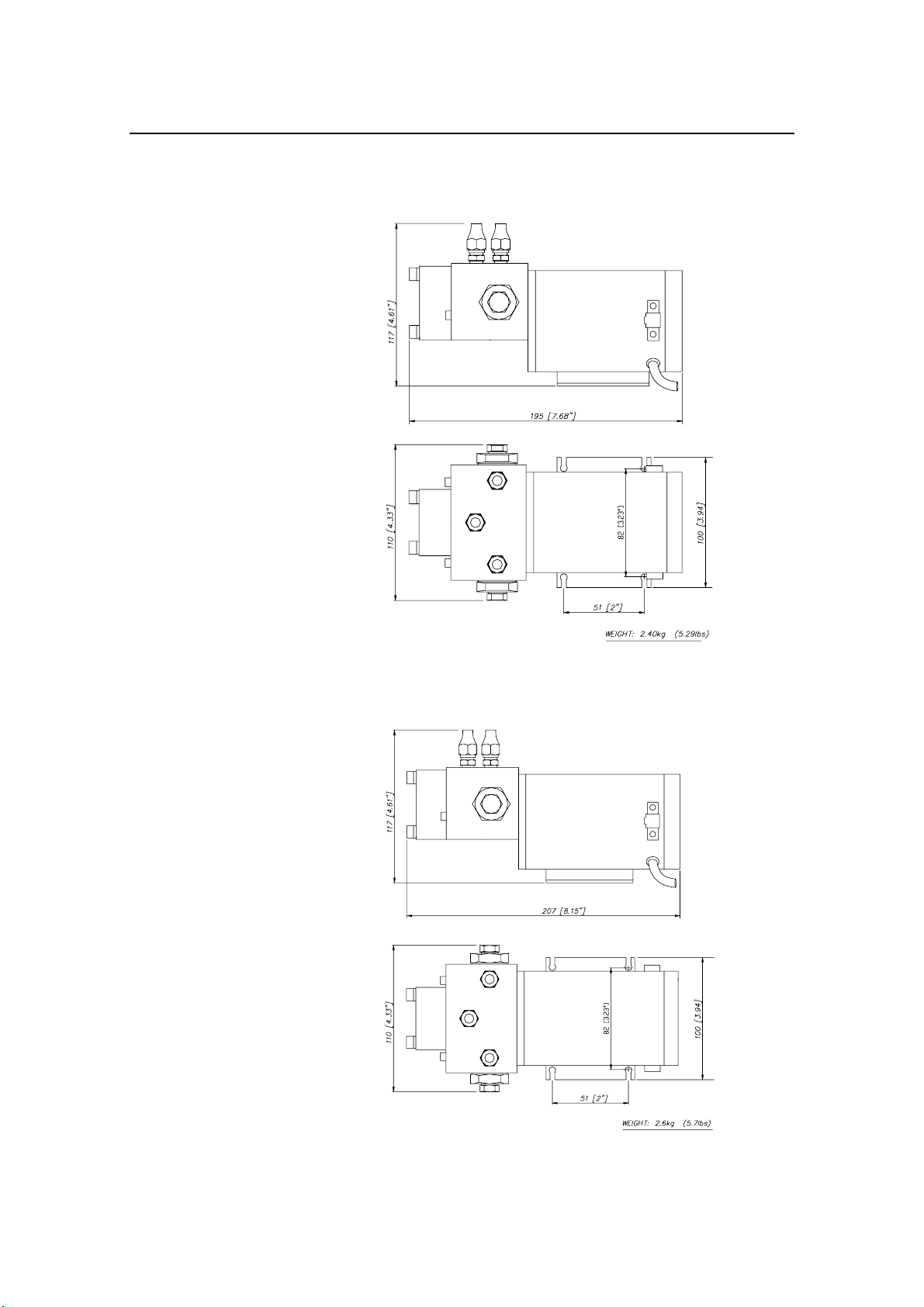
8.2 Dimensions
Figure 8-1
RPU80 Dimensions
Drw.no. N3-111836
Figure 8-2
RPU160 Dimensions
Drw.no. N3-111835
30 20220422N
www.Busse-Yachtshop.de email: [email protected]
Page 33
Technical Specifications
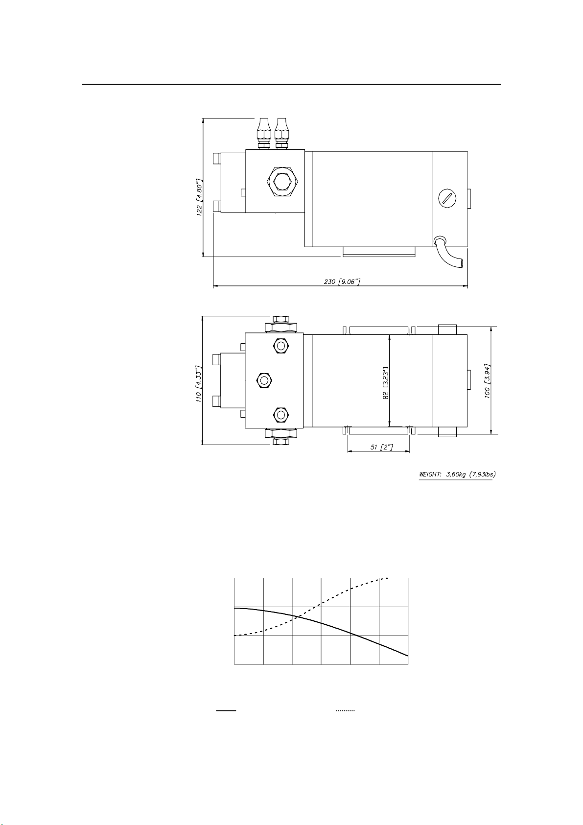
8.3 RPU80 performance
1.5
1.0
0.5
CAPACITY (l/min)
0
10 20 30 40 50 60
PRESSURE (BAR)
Capacity versus
pressure
Figure 8-3
RPU300 Dimensions
Drw.no. N3-111834
Current versus
pressure
9
6
AMPS
3
0
20220422N 31
www.Busse-Yachtshop.de email: [email protected]
Page 34
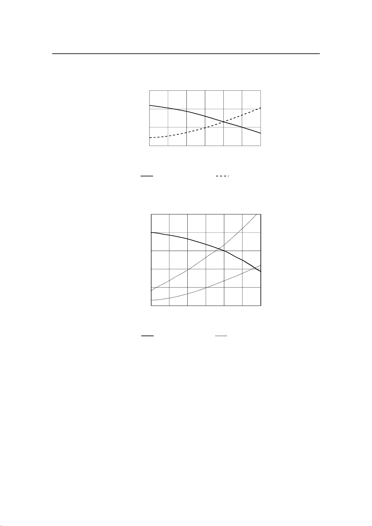
Simrad Reversible Pump RPU80/160/300
8.4 RPU160 performance
2.0
1.5
1.0
CAPACITY (l/min)
0.5
0
10 20 30 40 50 60
PRESSURE (BAR)
Capacity versus
pressure
8.5 RPU300 performance*
3.5
3.0
2.5
2.0
V
2
CAPACITY (l/min)
1.5
1.0
* Measured at charging voltage.
1
V
4
2
0
10 20 30 40 50 60
PRESSURE (BAR)
Capacity versus
pressure
23
17
11
Current versus
pressure
20
15
10
Current versus
pressure
AMPS
5
30
25
AMPS
5
32 20220422N
www.Busse-Yachtshop.de email: [email protected]
Page 35
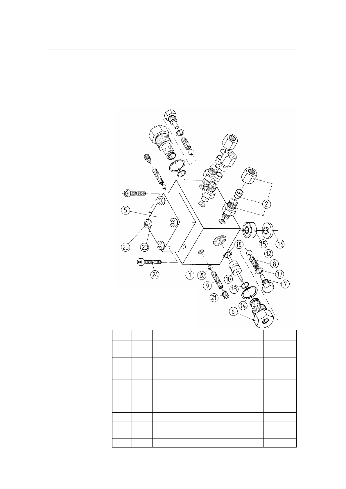
9 SPARE PARTS
9.1 RPU80/RPU160/RPU300
Spare Parts
Figur 9-1
Gear pump
RPU80/RPU160/RPU300
Assembly drawing
Pos. Qty. Gear pump parts Part no.
1 1 Valve block 21100250
2 3 Fitting complete 7/16-20UNF 44166767
2 3
5 1 Pump cover RPU80/160
6 2 Valve housing 21100276
7 2 Plug 21100292
8 2 Spring 21100193
9 2 Spring 21100391
10 1 Slide 21100268
12 2 Steel ball Ø8 44149656
20220422N 33
Fitting US model complete:
Nut 3/8” with 5/8”x18 SAE
Fitting SAE 5/8”-18-7/16-20UNF
Pump cover RPU300
21101399
44155927
44166775
21101191
21111018
www.Busse-Yachtshop.de email: [email protected]
Page 36
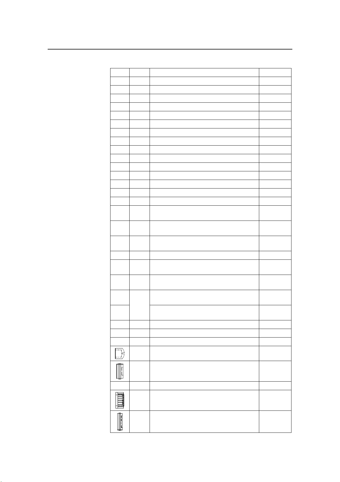
Simrad Reversible Pump RPU80/160/300
13 2 O-ring 9,25x1,78 Nitrile 44149649
14 2 Copper washer Ø10,2x14x1,5 44149706
15 1 Oil seal 8x22x7 44149722
16 1 Support ring 21100185
17 2 Copper washer Ø10,2x14x1 44148146
18 1 O-ring 9,25x1,78 Silicon, red 44154656
20 2 Steel ball Ø6,35 44118552
21 2 Grub. Screw sock. head M8x10 44149904
23 4 Split washer M6 A2 44150050
24 2 Screw sock. head M5x60 A2 44149912
25 4 Screw sock. head M6x35 A2 44152775
1 Gear wheel (1) RPU80/160 21100169
1 Gear wheel (2) RPU80/160 21100227
1 Gear wheel (1) RPU300 21111926
1 Gear wheel (2) RPU300 21111034
Motor parts (LEMAC)
1 RPU80 Lemac motor
(Substitutes RPU80 Fracmo motor)
1 RPU160 Lemac motor
(Substitutes RPU160 Fracmo motor)
2 Brush for RPU80/160 Lemac motor, C8386
9x6x18,2mm
2 Brush cap for RPU80/160 Lemac motor 44170132
1 RPU300 Lemac motor, 12V
(Substitutes RPU300 Fracmo motor, 12V)
1 RPU300 Lemac motor, 24V
(Substitutes RPU300 Fracmo motor, 24V)
Brush for RPU300 Lemac motor, short type,
2 Brush cap for RPU300 Lemac motor 44170124
2 Brush for RPU160 Fracmo motor 44161941
2
12,7x7,94x12mm
Brush for RPU300 Lemac motor, long type,
12,7x7,94x19mm
2 Brush cap RPU80/160 Fracmo – Type I 44163228
2 Brush cap RPU80/160 Fracmo – Type II 44163236
Parts for Fracmo motors:
44170199
44177525
44169845
44170009
44169993
44170116
44170108
2 Brush for RPU300 Fracmo motor 44161925
2 Brush cap RPU300 Fracmo – Type I 44163244
2 Brush cap RPU300 Fracmo – Type II 44163251
34 20220422N
www.Busse-Yachtshop.de email: [email protected]
Page 37
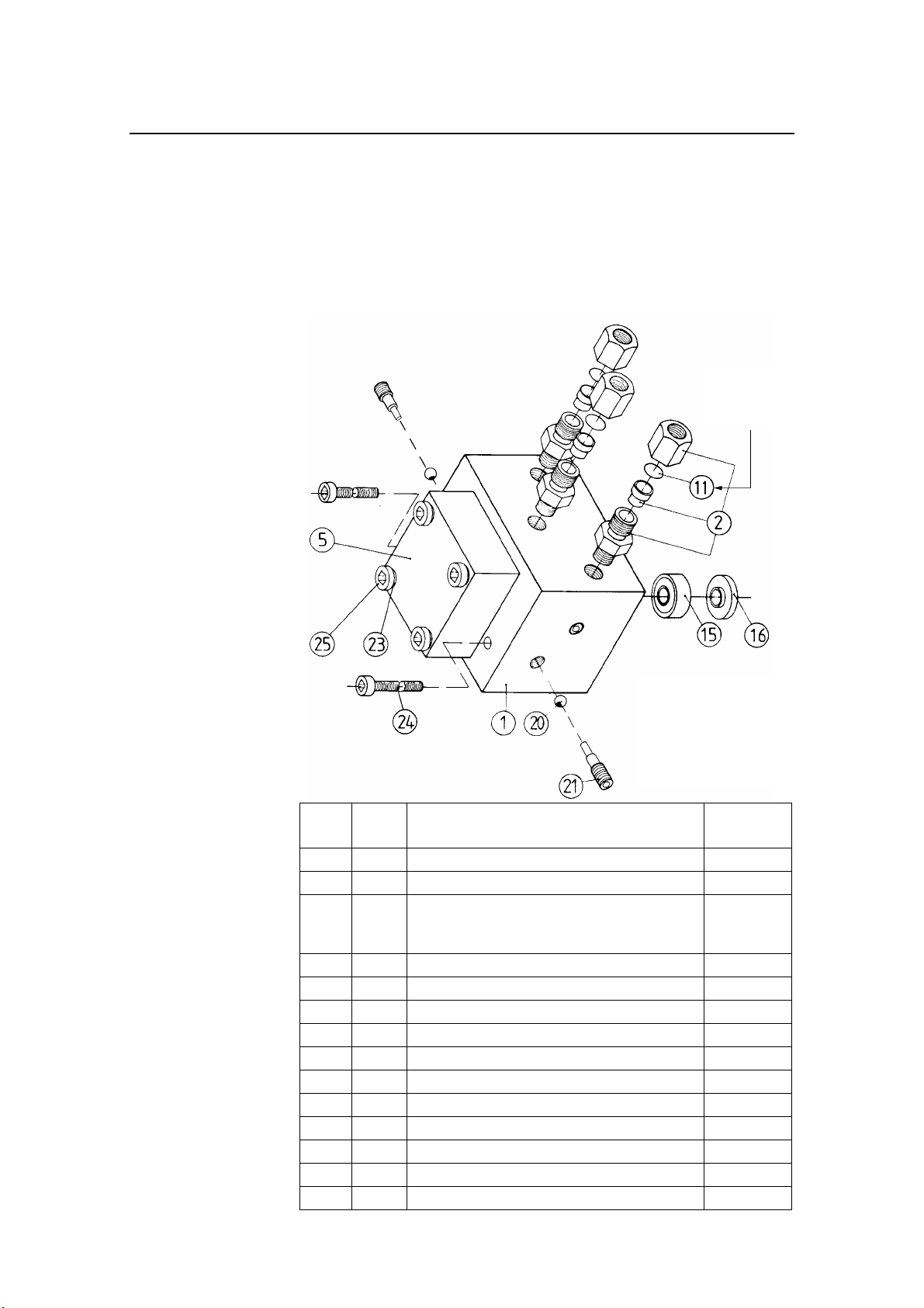
9.2 RPU80 – Previous model gear pump
RPU80 Reversible Pump with ser. no. 1317 H02 onwards (P/N
21116165) and 1805 H03 onwards (P/N 21116181 – US
version) have identical gear pump with the RPU160 (see figure
9-1).
Spare Parts
Removed at
installation
Figur 9-2
Gear pump
Previous model of RPU80
Assembly drawing
Pos. Qty. Gear pump parts
(Previous RPU80 model)
1 1 Valve block, Previous model 21116256
2 3 Fitting complete 44158483
2
5 1 Pump cover RPU80/160 21101191
11 3 Cover (Removed at installation) 21217047
15 1 Oil seal 8x22x7 44149722
16 1 Support ring 21100185
20 2 Steel ball Ø6,35 44118552
21 2 Grub. Screw sock. head M8x10 21112933
23 4 Split washer M6 A2 44150050
24 2 Screw sock. head M5x60 A2 44149912
25 4 Screw sock. head M6x35 A2 44152775
1 Gear wheel (1) RPU80/160 21100169
1 Gear wheel (2) RPU80/160 21100227
20220422N 35
US model:
3
Nut 3/8” with 5/8”x18 SAE
3
Fitting SAE 5/8”-18-45
Part no.
44155927
44158491
www.Busse-Yachtshop.de email: [email protected]
Page 38

Simrad Reversible Pump RPU80/160/300
10 SALES AND SERVICE WORLDWIDE 010304
EUROPE
AUSTRIA
Allroundmarin-Alltechnik
GesmbH
Rheinboldtstrasse 11-13
A-2362 Biedermannsdorf b.Wien
Tel.: +43 2236 646 760
Fax: +43 2236 63135
www.allroundmarin.com
BENELUX
Simrad BV
P. O. Box 587
3200 AM Spijkenisse
Tel.: +31 181 600234
Fax: +31 181 626688
www.bennexholland.nl
CROATIA
Almar d.o.o.
Porec - Kamenarija 12
52452 Funtana
Tel.: +385 52 445 005
Fax: +385 52 445 276
CYPRUS
Regis Marine Electr. Ltd.
163 Leontiou A Street
PO Box 56320
CY-3360 Limassol
Tel.: +357 25 366977
Fax: +357 25 347209
DENMARK
Simrad AS (DK)
Naverland 22
DK-2600 Glostrup
Tel.: +45 43 44 49 00
Fax: +45 43 44 48 99
www.simrad.dk
ESTONIA
Balti Merekaatrid
Marine Department
Pärnu Mnt. 232
11314 Tallinn
Tel.: +372 67 10 002
Fax: +372 67 10 076
FINLAND
(Professional)
AT - Marine OY
Mesikukantie 16
FIN 01300 Vantaa
Tel.: +358 9 5494 2600
Fax: +358 9 5494 2700
www.atmarine.fi
(Recreational)
Oy Maritim Ab
Veneentekijäntie 1
SF 00210 Helsinki
Tel: +358 9 681 631
Fax: +358 9 692 7917
www.maritim.fi
FRANCE
Simrad S.A.
Parc d’Activités Ragon
23 Avenue Pasteur
44 119 Treillieres
Tel.: +33 2 28 01 23 01
Fax: +33 2 28 01 21 43
www.simrad.fr
GERMANY
Simrad GmbH & Co. KG
Dithmarscher Strasse 13
26723 Emden
Tel.: +49 4921 96860
Fax: +49 4921 968677
www.simrad.de
GREAT BRITAIN
Simrad
Unit 810, Fareham Reach
166 Fareham Road, Gosport
Hampshire PO13 0FW
Tel.: +44 1329 245100
Fax: +44 1329 245111
www.simrad.com
GREECE
Aegean Electronics S.A.
1-3, Akti Miaouli Str.
EL-185 35 Piraeus
Tel.: +302 10 413 7269
Fax: +302 10 413 7270
ICELAND
Fridrik A. Jonsson ehf
Eyjarslod 7
P.O.Box 362
121 Reykjavik
Tel.: +354 552 2111
Fax: +354 552 2115
ITALY
Simrad Srl.
Viale Odone Belluzzi 57
00128 Rome
Tel.: +39 06 5078 1022
Fax: +39 06 5078 1024
www.simrad.it
MALTA
Medcomms Ltd.
4 Msida Rd.
Gzira GZR03
Tel.: +356 21 335521
Fax: +356 21 310820
NORWAY
Simrad Marine AS
Joh. Berentsensvei 109
P.O. Box 53, Laksevåg
N-5847 Bergen
Tel.: +47 55 94 10 00
Fax: +47 55 94 10 05
www.simrad.no
POLAND
Escort Ltd. Electronics Syst.
Ul. Energetyków 9
70-656 Szczecin
Tel.: +48 91 462 4379
Fax: +48 91 462 4408
www.escort.com.pl
PORTUGAL
Nautel - Sistemas Maritima Lda.
Edificio Liscont, 1’
Cais de Alcantara
1399-037 Lisboa
Tel.: +351 21 392 0940
Fax: +351 21 392 0949
www.nautel.pt
RUSSIA
Moretron Service Ltd.
SIVA Center
Podgornaya Str. Rybny Port
183001 Murmansk
Tel.: +7 8152 459781
Fax: +7 8152 459791
www.moretron.ru
Simbia Engineering Company,
Ltd.
4A Verhneozernaja Str.
236018 Kaliningrad
Tel.: +7 0112 215492
Fax: +7 0112 365380
Norwegian Partners
Marine AS
5-A Svetlanskaya Str.
690091 Vladivostok
Tel.:+7 4232 414627
Fax.:+7 4232 300457
www.npm.no
SPAIN
Simrad Spain, S.L.
Partida Torres N° 38
Nave 8 Y 9
03570 Villajoyosa (Alicante)
Tel.: +34 96 681 01 49
Fax: +34 96 685 23 04
www.simrad.sl
SWEDEN
Simrad AB
Svalörtsgatan 14
42668 Västra Frölunda
Tel.: +46 31 69 51 00
Fax: +46 31 69 51 20
www.simrad.se
SWITZERLAND
Marine Parts Heimgartner
Pfäffikerstr. 6
CH 8604 Volketswil/Zürich
Tel.: +41 1 997 40 90
Fax: +41 1 997 40 94
TURKEY
Promar Marine Equip. Ltd.
Igrip Sokak Gul Apt. No: 7/2
81030 Fenerbahce
Istanbul
Tel.: +90 216 3460894
Fax: +90 216 3461493
www.promar.com.tr
AFRICA
MOROCCO
Soremar
17 Rue le Catelet
BD Emile Zola
21900 Casablanca
Tel.: +212 22 40 50 50
Fax: +212 22 24 82 36
NORTH WEST
AFRICA
Simrad NW Africa
1, Place Al Istiqlal
Angle Ave. Des FAR
20000 Casablanca
Morocco
Tel.: +212 22 54 1816/1535
Fax: +212 22 54 15 37
SOUTH AFRICA
Marine Radio Acoustic Devices
P. O. Box 12076
N1 City 7463
Cape Town
Tel.: +27 21 559 4003
Fax: +27 21 559 2752
MIDDLE EAST
ISRAEL
YAMIT Y.S.B LTD.
P. O. Box 6158
61061 Tel-Aviv
Tel.: +972 3 5271 778
Fax: +972 3 5271 772
UNITED ARAB
EMIRATES
Emphor FXCO
P. O. Box 6488
Dubai
Tel.: +971 4 324 7500
Fax: +971 4 324 7503
LEBANON
Selcom Marine Sarl
P. O. Box 55541
Dekwaneh Main Street
Beirut
Tel.: +961 149 1489
Fax: +961 149 5325
IRAN
Darya Negar Co.
Office 2, 1st Floor,
Bldg. No. 64
Fatemi Square
Teheran
Tel.: +98 21 896 7872
Fax: +98 21 896 6658
PACIFIC
AUSTRALIA
Quin Marine Pty. Ltd.
89 St Vincent Street
Port Adelaide, SA 5015
Tel.: +61 88 447 1277
Fax: +61 88 341 0567
NEW ZEALAND
Advance Trident Ltd.
P.O. Box 4174
Kingsland
Auckland
Tel.: +64 9 845 5347
Fax: +64 9 845 5348
www.advancetrident.com
ASIA
SINGAPORE
Jason Electronics Pte Ltd.
Blk 194 Pandan Loop #06-05
Pantech Industrial Complex
Singapore 128383
Tel.: +65 6 872 0211
Fax: +65 6 872 1800
CHINA & HONG KONG
CITE Limited
Rm C-E, 16/F, Yan’s Tower,
26-27 Wong Chuk Hang Road ,
Aberdeen
Tel.: +852 2 552 0178
Fax: +852 2 873 0679
INDIA
Norinco Pvt Ltd.
Karshaka Road
Cochin 682016
Tel.: +91 484 2323 675
Fax: +91 484 2323 694
INDONESIA
PT Sarana Teknologi Samudera
Wisma Dharmala Sakti
Annexe Building 7th Floor
JL. Jenderal Sudirman Kav.32
Jakarta 10220
Tel.: +62 21 570 61 28
Fax: +62 21 570 72 21
SOUTH KOREA
Lucky Susan Co. Ltd.
K.P.O. Box 1666, Seoul
Taesung B/D. #508
60-17, Taepyong-Ro 1-Ka
Chung-Ku, Seoul
Tel.: +82 2 736 4328
Fax: +82 2 739 5689
Turn-On Electronics Co.
th
fl., Dong-A Ilbo Bldg.
7
53-11, 4-KA,
Choongang-Dong
Choong-Ku, Pusan
Tel.: +82 51 462 3930
Fax: +82 51 462 3089
JAPAN
Nippon Kaiyo Co, Ltd.
9-2 Sakae-Cho
Kita-Ku
Tokyo 114-0005
Tel.: +81 3 3913 2337
Fax: +81 3 3913 3479
Shipmate Japan Co. Ltd. 2-5-4
Fukuura
Kanazawa-ku
Yokohama 236-0004
Tel.: +81 45 788 2731
Fax: +81 45 788 2732
TAIWAN
Dragon & Elephant Enterprise
Co. Ltd.
12F-4, No. 251
Min Chuan 1st Road
Kaohsiung, Taiwan ROC
Tel.: +886 722 72887
Fax: +886 722 72910
AMERICAS
CANADA
Simrad Canada Ltd.
P.O. Box 397
112 Lincoln Street
Lunenburg, Nova Scotia
Canada B0J 2C0
Tel.: +1 902 640 3300
Fax: +1 902 640 3070
www.simrad.com
USA
Simrad Inc.
19210 33rd Avenue West
Suite A
Lynnwood WA 98036
Tel.: +1 425 778 8821
Fax: +1 425 771 7211
www.simrad.com
Simrad Inc.
1500 NW 1st Street
Suite 1-E
Dania, FL 33004
Tel.: +1 954 922 7700
Fax: +1 954 922 0707
www.simrad.com
ARGENTINA
R.C. International
Av. Corrientes 2958 11
1193 Buenos Aires
Tel.: +54 11 4862 5774/4865
7621
Fax: +54 11 4862 5774
BRAZIL
Demo Offshore Ltda
Av. Marechal Camara 160
Sala 614,
Centro Rio de Janeiro
RJ-20020-080
Tel.: +55 21 2524 5171
Fax: +55 21 2532 0254
CHILE
Simrad S.A.
Casilla 19012, Correo 19
Vitacura
Santiago
Tel.: +56 2 207 3059
Fax: +56 2 207 2695
PERU
Simrad Peru S.A.
Calle Los Topacios 266-268
Urb. San Antonio
Bellavista – Callao
Tel.: +51 1 453 7477
Fax: +51 1 453 7325
URUGUAY
Electromaritima Uruguaya Ltda.
Guatemala 1260
11800 Montevideo
Tel.: +59 8 2 924 7139
Fax: +59 8 2 924 7138
The above companies
represent only main
importers. Each country is in
addition served by a network
of local service outlets.
Some importers represent
only specific market
segments according to the
following codes:
Professional:
Coastal and Fishery market
Recreational:
Leisure market
www.simrad.com
th
38
36 20220422N
www.Busse-Yachtshop.de email: [email protected]
 Loading...