

Page 1

ENGLISH
10 kW and 25 kW
Low Emission Radar
Installation Manual
Page 2

Preface
As Navico is continuously improving this product, we retain the right to make changes to the
product at any time which may not be re ected in this version of the manual. Please contact
your nearest distributor if you require any further assistance.
It is the owner’s sole responsibility to install and use the instrument and transducers in a
manner that will not cause accidents, personal injury or property damage. The user of this
product is solely responsible for observing safe boating practices.
NAVICO HOLDING AS AND ITS SUBSIDIARIES, BRANCHES AND AFFILIATES DISCLAIM ALL
LIABILITY FOR ANY USE OF THIS PRODUCT IN A WAY THAT MAY CAUSE ACCIDENTS, DAMAGE
OR THAT MAY VIOLATE THE LAW.
Governing Language: This statement, any instruction manuals, user guides and other
information relating to the product (Documentation) may be translated to, or has been
translated from, another language (Translation). In the event of any con ict between any
Translation of the Documentation, the English language version of the Documentation will be
the o cial version of the Documentation.
This manual represents the product as at the time of printing. Navico Holding AS and its
subsidiaries, branches and a liates reserve the right to make changes to speci cations
without notice.
Warranty
The warranty card is supplied as a separate document.
Declarations and conformance
This equipment is intended for use in international waters as well as coastal sea areas
administered by countries of the E.U. and E.E.A.
Compliance Statements
The Simrad TXL-10S-4, TXL-10S-6, and TXL-25S-7:
* Comply with CE under R&TTE directive 1999/5/EC.
* Comply with the requirements of level 3 in Australia and level of conformity 3 in New
Zealand.
This device complies with Part 15 of the FCC Rules. Operation is subject to the following two
conditions: (1) this device may not cause harmful interference, and (2) this device must accept
any interference received, including interference that may cause undesired operation.
Industry Canada
IC RSS-GEN, Sec 7.1.3 Warning Statement- (Required for license-exempt devices)
This device complies with Industry Canada license-exempt RSS standard(s). Operation is
subject to the following two conditions: (1) this device may not cause interference, and (2)
this device must accept any interference, including interference that may cause undesired
operation of the device.
Page 3
IC RSS-GEN, Sec 7.1.2 Warning Statement- (Required for Transmitters)
Under Industry Canada regulations, this radio transmitter may only operate using an antenna
of a type and maximum (or lesser) gain approved for the transmitter by Industry Canada.
To reduce potential radio interference to other users, the antenna type and its gain should
be so chosen that the equivalent isotropically radiated power (e.i.r.p.) is not more than that
necessary for successful communication.
IC RSS-GEN, Sec 7.1.2 Warning Statement- (Required for Transmitters w/ detachable antennas)
The radio transmitters 768C-NKE2103, and 768C-NKE2254 have been approved by Industry
Canada to operate with the antenna types listed below with the maximum permissible
gain and required antenna impedance for each antenna type indicated. Antenna types not
included in this list, having a gain greater than the maximum gain indicated for that type, are
strictly prohibited for use with this device.
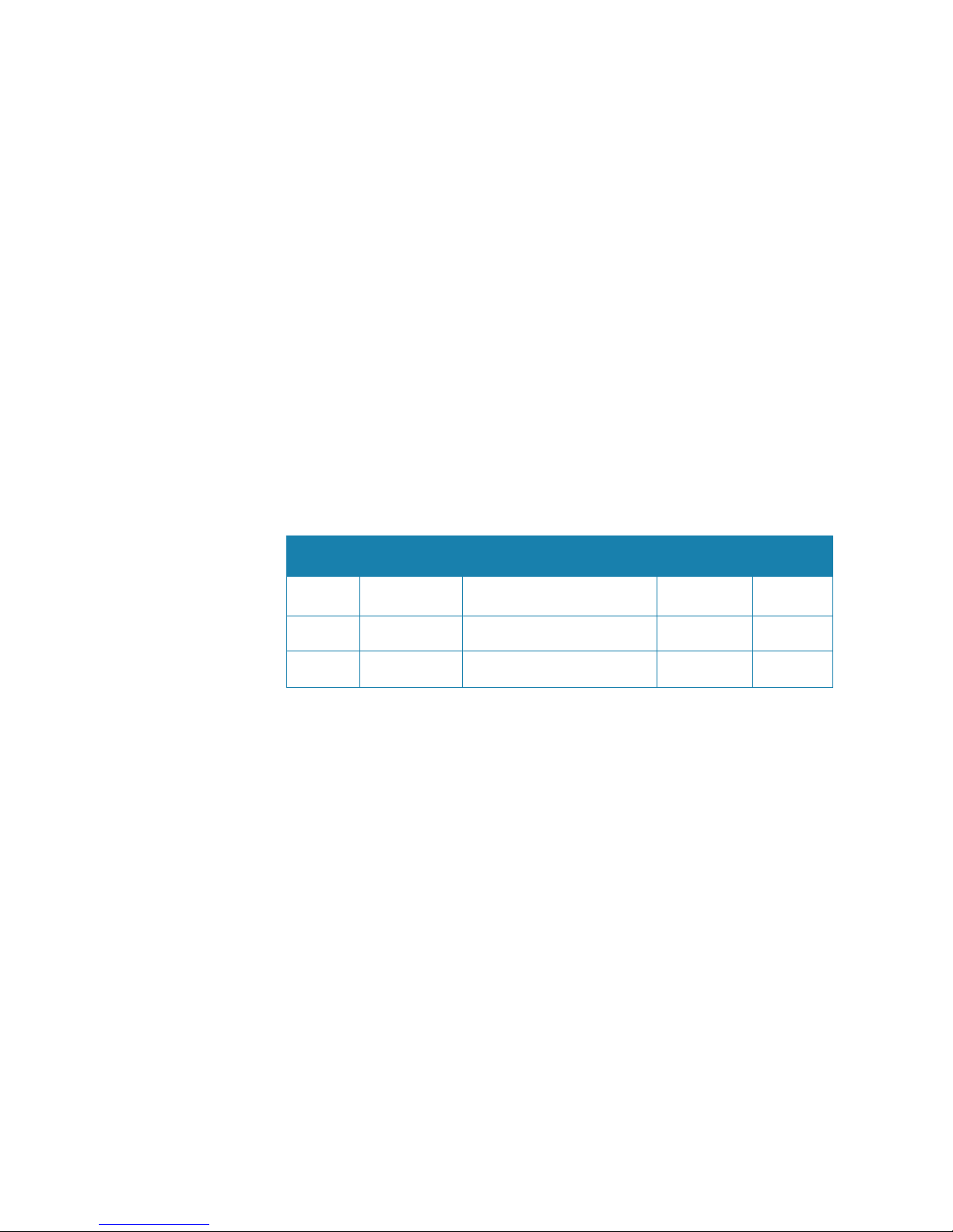
System
Model
Transmitter
Antenna part number/
description
antenna gain
(dBi)
impedence
(nominal)
TXL-10S-4 768C-NKE2103 151-10359-001 - 4 foot antenna 27.9 dBi 50 ohm
T
XL
-10S-6 768C-NKE2103 151-10360-001 - 6 foot antenna 29.9 dBi 50 ohm
TXL-25S-7 768C-NKE2254 151-10361-001 - 7 foot antenna 30.7 dBi 50 ohm
note: only the antenna and transmitter pairing shown in table above may be used.
IC RSS-102, Sec 2.6 Warning Statement
The user manual of devices intended for controlled use shall also include information
relating to the operating characteristics of the device; the operating instructions to ensure
compliance with SAR and/or RF eld strength limits; information on the installation and
operation of accessories to ensure compliance with SAR and/or RF eld strength limits; and
contact information where the user can obtain Canadian information on RF exposure and
compliance. Other related information may also be included.
Page 4
Harmful Interference
The user is cautioned that any changes or modi cations not expressly approved by
the party responsible for compliance could void the user’s authority to operate the
equipment.
This equipment has been tested and found to comply with the limits for a Class B digital
device, pursuant to Part 15 of the FCC rules. These limits are designed to provide
reasonable protection against harmful interference in a residential installation. This
equipment generates, uses and can radiate radio frequency energy and, if not installed
and used in accordance with the instructions, may cause harmful interference to radio
communications. However, there is no guarantee that the interference will not occur in
a particular installation. If this equipment does cause harmful interference to radio or
television reception, which can be determined by turning the equipment o and on, the
user is encouraged to try to correct the interference by one or more of the following
measures:
Reorient or relocate the receiving antenna
• Increase the separation between the equipment and receiver
• Connect the equipment into an outlet on a circuit di erent from that of the receiver
• Consult the dealer or an experienced technician for help
Trademarks
• NMEA 2000 is a registered trademark of the National Marine Electronics Association
• Navionics is a registered trademark of Navionics SpA
• Simrad is a trademark of Kongsberg Maritime AS Company registered in the US and other
countries and is being used under license
• B&G, StructureScan, Navico, SonicHub, SimNet, Skimmer, InsightHD, Broadband Radar
and Broadband Sonar are trademarks of Navico, registered in the US and other countries
About this manual
This manual is a reference guide for installing the Simrad TXL-10S-4, TXL-10S-6, and TXL-25S-7.
The manual does not cover basic background information about how equipment such
as radars, echosounders and AIS work.
Important text that requires special attention from the reader is emphasized as follows:
Note: Used to draw the reader’s attention to a comment or some important information.
!Warning: Used when it is necessary to warn personnel that they should proceed
carefully to prevent risk of injury and/or damage to equipment/personnel.
Page 5

| 1
Contents | 10kW and 25kW Installation Manual
Contents
2 Introduction
4 Pre installation checks
4 Check the parts
4 Choose the scanner location
5 Power boat installations
6 How to nd the A-B Line:
6 How to nd the theoretical maximum detection range
7 Reduce false echoes and shadow zones
9 Hardware mounting
9 Install the radar processor
10 Install the scanner
12 Wiring
12 Guidelines
12 Radar scanner: 10 kW
15 Radar scanner: 25 kW
18 Radar processor connections
21 Pinouts
21 Scanner cable
22 NMEA / COMMS cable
23 Speci cations
23 TXL-10S-4/TXL-10S-6TXL-25S-7
25 Drawings
25 10 kW scanner
26 25 kW scanner
27 Radar processor
Page 6
2 |
Introduction |10kW and 25kW Installation Manual
Introduction
This manual explains how to install the radar scanner (antenna + pedestal) and the Navico
radar processor. There are also details how to connect the radar to the various brands of
displays produced by Navico.
This manual should be used in conjunction with the installation manual provided with the
display.
This manual is written for professional marine technicians, installation technicians, and service
technicians. Dealers may use information contained in this document.
The radar systems consist of a scanner, radar processor and connection cables. Scanner
models are available with power outputs of 10 kW and 25 kW to suit di erent customer
requirements. Each scanner model has a corresponding radar processor module.
The radar system is intended for use in a marine environment. It consists of an open antenna
scanner connected to a radar processor module by a prefabricated interconnection cable. The
interconnection cable must be installed by a quali ed radar technician. An ethernet network
cable is used to connect the radar processor to the system display.
!
Warning: The scanner cable should only be installed by a quali ed radar technician
!Warning: Use the radar at your own risk. Your radar is designed as a navigation aid. It
should not be used for purposes that require precise measurements of direction, distance,
topography or location. Always compare the navigation information received from your
radar with data from other navigation aids and sources. When a con ict arises between the
navigation data from your radar and data from other navigation aids, make sure you resolve
the con ict before proceeding with navigation.
A CAREFUL NAVIGATOR NEVER RELIES ON ONLY ONE METHOD TO OBTAIN NAVIGATION
INFORMATION.
International Regulations for Preventing Collisions at Sea mandate that when radar is on
a vessel, the radar must be used at all times, regardless of weather conditions or visibility.
Numerous court decisions have ruled that the radar must be used, and the radar operator
must know all operational aspects of radar performance. Otherwise they will face a greater
risk of liability if an accident occurs.
!
Warning: High Voltage Hazard
There are dangerously high voltages present within the radar pedestal unit.
Technicians must ex
ercise extreme care when working inside the unit. ALWAYS remove
power before removing the cover. Some capacitors may take several minutes to discharge,
even after switching o the radar. Before touching the magnetron or any high voltage
components, ground them with a clip lead.
!
Warning: Microwave Radiation Hazard
The microwave energy radiated by a radar antenna is harmful to humans, especially
to the ey
es. NEVER look directly into an open waveguide or into the path of radiation
from an enclosed antenna. Radar and other radio frequency radiation can upset cardiac
pacemakers. If someone with a cardiac pacemaker suspects abnormal operation,
immediately turn o the radar equipment and move the person away from the antenna.
Turn o the radar whenever it is necessary to work on the antenna unit or other equipment
in the beam of the radar.
1
Page 7

| 3
Introduction | 10kW and 25kW Installation Manual
Note: Most countries accept that RF power density levels below 100 W/m cause no signi -
cant RF hazard.
Radio Frequency (RF) Exposure Information
Calculations for radar systems in table below show that the safe distance (for a rotating
antenna) is within the antenna’s turning circle. Irrespective, users should stay well outside the
turning circle of the antenna to avoid injury through impact as it spins.
System
100W/m
or power at
Antenna face
50W/m
(measurement
distance, cm)
10W/m
(measurement
distance, cm)
2.5W/m
(measurement
distance, cm)
10kW:
TXL-10S-4
TXL-10S-6
32.8 W/m N/A 26cm (0.86 ft) 123cm (4.04 ft)
25kW:
TXL-25S-7
74.7 W/m 5cm (0.16 ft) 81cm (2.66 ft) 162cm (5.31 ft)
Note: Limits apply to exposure within the vertical beam angle.
Note: The safe range for a non-rotating antenna is far greater due to the lack of averaging,
however this is not a permitted operational mode and the system includes interlocks to
prevent this mode of operation.
FCC labels
10kW (4 foot & 6 foot):
FCC ID: CKENKE2103
IC : 768C-NKE2103
!
SERIAL 1406J3LC00001
COMPASS SAFE DISTANCE
STD 2.4m STEER 1.8m
SERIAL 1406J3LC00001
!
25kW (7 foot, two labels):
MODEL: TXL-25S-7
FCC ID: CKENKE2254
IC: 768C-NKE2254
0560
!
MADE IN JAPAN
COMPASS SAFE DISTANCE
STD 2.4m STEER 1.8m
SERIAL 1406J3LM00001
UNIT: NKE-2254-7
MODEL:TXL-25S-7
Countries of intended use in the EU:
AT - Austria
BE - Belgium
BG - Bulgaria
CY - Cyprus
CZ - Czech Republic
DK - Denmark
EE - Estonia
FI - Finland
FR - France
DE - Germany
GR - Greece
HU - Hungary
IS - Iceland
IE - Ireland
IT - Italy
LI - Liechtenstein
LV - Latvia
LT - Lithuania
LU - Luxembourg
MT - Malta
NL - Netherlands
NO - Norway
PL - Poland
PT - Portugal
RO - Romania
SK - Slovakia
SI - Slovenia
ES - Spain
SE - Sweden
CH - Switzerland
TR - Turkey
UK - United Kingdom
Page 8

4 |
Pre installation checks |10kW and 25kW Installation Manual
Pre installation checks
!Warning: A radar unit should only be installed by a quali ed marine technician, as
potentially lethal high voltage is present along with heavy rotating parts.
There is a transmit interlock that prevents radar transmissions if the antenna is not rotating.
However, a high voltage remains for a period of time after the system is turned o . If you
are not familiar with this type of electronics, consult with a trained service or installation
technician before attempting to service any part of the equipment.
Installation includes:
• mechanical mounting
• electrical wiring
• con guring the display or network system to work with the radar
• adjusting the radar for proper performance
Don’t take any shortcuts, and follow these instructions carefully!
Check the parts
System TXL-10S-4 TXL-10S-6 TXL-25S-7 example
Antenna 4 foot 6 foot 7 foot
Pedestal NKE-2103-4 NKE-2103-6 NKE-2254-7
Processor 10 kW 10 kW 25 kW
Scanner cable 20 m 20 m 20 m
Ethernet adaptor 1 1 1
Ethernet cable, 1.8m
(6 ft)
11 1
Accessories
note: some hardware
is packed with the
antenna
brass washers, antenna bolts, mounting
bolts, washers, nuts, earthing strop &
bolt, fuses, mounting template
Choose the scanner location
The radar’s ability to detect targets depends greatly on the position of its scanner. The ideal
location for the scanner is well elevated, centered over the vessel’s keel line, and clear of as
many obstacles as possible on the same plane as the antenna.
A higher installation position increases the radar ranging distance, but it also increases the
minimum range around the vessel where targets cannot be detected.
2
Page 9

| 5
Pre installation checks | 10kW and 25kW Installation Manual
When you’re deciding on the location, please consider:
• To avoid the scanner coming in contact with other installed objects while it is rotating, ensure
that there is at least 200 millimeters between the swing circle (turning radius) and the other
installed objects. Observe the following swing circle when determining mounting location:
Scanner antenna diameter of swing circle
4 foot 1,320 mm
6 foot 1,910 mm
7 f
oot 2270mm
• The length of the interconnection cable supplied with your radar is usually su c
ient. If you
think you’ll need a longer cable, consult your dealer before installation, because a longer
cable may reduce the performance of the radar.
• If the roof of the wheelhouse is the highest existing location, consider installing a radar
mast or a pedestal on which you can mount the scanner. You may also need to construct a
working platform for your own safety during installation and servicing work.
• If you mount the scanner on a pedestal or base, ensure that rain and sea spray can drain away
from it rapidly.
• If you locate the scanner on the mast, position it on the forward side so that there is a clear
view to the front of the vessel.
• The scanner is usually installed parallel to the line of the keel.
• Ensure that the location site provides the scanner with a clear view of the front of the vessel.
DON’T DO THIS!
• DON’T install the scanner too high up, where its weight will alter the stability of the vessel and
cause degrade the radar picture over short ranges.
• DON’T install the scanner close to lamps or exhaust outlets. The heat emissions may cause
the equipment to break down. Soot and smoke will degrade the performance of the radar.
• DON’T install the scanner close to the antennas of other equipment such as direction nders,
VHF antennas, GPS equipment etc, as it may cause interference.
• DON’T install the scanner where a large obstruction (such as an exhaust stack) is at the same
level as the beam. The obstruction is likely to generate false echoes and/or shadow zones.
• DON’T install the scanner where it will be subjected to strong vibrations (such as a derrick
post) because these vibrations will degrade the performance of the radar.
• DON’T install a scanner close to halyards or ags because the wind or boat movement could
cause entanglement with the rotating antenna.
!Warning: DON’T install the scanner inside of the recommended compass safe
distances of any navigation instruments such as the magnetic compass and the
chronometer. The compass safe distances are as follows:
10 kW radar STD 2.4 m (7.9 ft) / STEER 1.8 m (6 ft)
25 kW radar STD 2.4 m (7.9 ft) / STEER 1.8 m (6 ft)
Power boat installations
Normally, you should install the scanner horizontally, to produce an equal sweep around the
boat:
Page 10
6 |
Pre installation checks |10kW and 25kW Installation Manual
However, when a power boat is traveling at high speed, the bow rises up out of the water and
if the elevation angle (trim) of the bow is raised up so that it equals, or exceeds, 50% of the
vertical beam width of the radar, this can cause two problems:
• Ahead of the power boat, the beam is projected too high to sweep the water surface
e ectively. Targets can be missed completely or appear at a very poor resolution on the
display screen.
• Astern of the power boat, the beam is projected too low and is concentrated over a small
area of water so that sea clutter becomes a problem on the display screen.
In this case, you’re recommended to install the scanner so that it is tilted down at the front,
at an angle that will produce an almost horizontal sweep when the power boat is running at
speed.
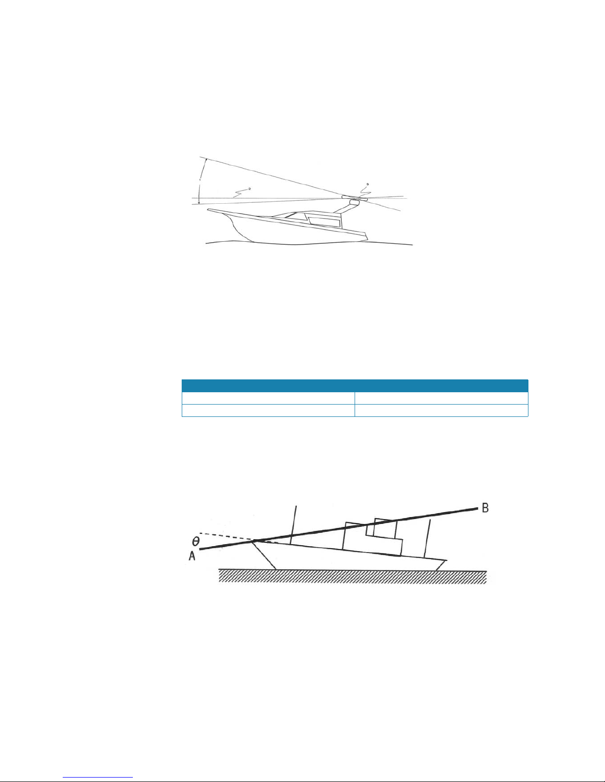
The optimum height for the scanner is as close as possible to the A-B line for best
performance.
How to nd the A-B Line:
The vertical extent of the radar beam is 20°, so most of the radar beam is concentrated within
this angle, meaning that outside of this angle, the radar beam will be very weak.
Scanner power θ° value (half the -3 dB beam width)
10 kW 10
25 kW 10
An example of an A-B Line is sho
wn in the picture. If you install the scanner below the
A-B line, the scanner will be t
oo low. It will be di cult to acquire distant targets and the
superstructure will be more likely to impede the passage of the beam and generate false
echoes.
If the scanner is installed too high above the A-B line, the beam will miss close targets and
increase sea clutter return.
You can nd the A-B line for any vessel as follows:
• Using a scaled drawing of the vessel, lay a rule along the line of the main deck and continue
this forwards as a dashed line extending beyond the bow.
• Using a protractor, measure the θ° value (for your scanner model) below the dashed line at
the bow and draw in a new line along this angle.
• Extend the new line back beyond the bow of the vessel. This is the A-B line.
How to nd the theoretical maximum detection range
Propagation of the radar beam can vary, depending on the properties of the air through
which it is traveling. Under normal conditions the maximum distance a target can be
detected at is approimately 10% beyond the optical horizon.
Page 11

| 7
Pre installation checks | 10kW and 25kW Installation Manual
You can calculate the maximum theoretical target detection range using the following
formula:
D = 2.23 (√h1 + √h2)
D
h1
h2
where:
• D is distance traveled by the radar beam
• h1 is the height above sea level of the scanner
• h2 is the height above sea level of a target
An example is shown below:
In this example, the scanner is installed on the vessel at a height of 3 m (10 ft) above sea level
(h1). Island A is 10 m (33 ft) high (h2) and for comparison, island B is 5 m (16.4 ft) high (h2).
Both islands are at a distance (D) of 10 nautical miles from the vessel.
Calculations using the formula show that, at this distance, the radar can only detect objects
that are more than 7.6 m (25 ft) high, which means that island A is shown on the radar but
island B is not shown.
Remember that:
• The maximum detection range of the radar is limited by the curvature of the earth’s surface
under normal conditions of wave propagation.
• Bad weather conditions can reduce the maximum detection range.
Reduce false echoes and shadow zones
False echoes can be produced on the radar display if the scanner is installed too close to an
object on the vessel’s superstructure. This object can block the radar beam and re ect it back,
generating false echoes and shadow zones.
If you are having problems with false echoes and/or shadow zones, re-install the scanner at a
higher location where the radar beam will be clear of any obstructions.
If this is not possible, try relocating the scanner away from the central keel line of the vessel to
the starboard side. This will move any shadows to the port side, maximize the radar view of
your give way sector, and ensure a clear view of the area around the vessel at the bow.
Use the following formula to calculate the distance that you’ll need to move the scanner:
Ls = 0.4R + D/2 (when R is less than 49 ft [15 m])
Ls = 0.025R + D/2 (When R is greater than or equal to 49 ft [15 m])
where:
Ls = distance to be moved from the keel line
Page 12

8 |
Pre installation checks |10kW and 25kW Installation Manual
D = diameter of the obstacle
R = distance between the antenna and the obstacle
Page 13

| 9
Hardware mounting | 10kW and 25kW Installation Manual
Hardware mounting
Install the radar processor
Install the radar processor in a dry location away from spray, rain, drips and condensation.
It is preferable that the processor is mounted vertically, with the connectors facing
downwards. Avoid installing the processor with the connectors facing upwards, as any water
that may ingress the installation area or travels down the connected cables could pool
around the connectors. This would result in corroded connectors, or damage to the internal
eletronics.
The radar processor must be located where it can be easily connected to the ship’s ground,
the scanner cable, the power cable and the radar communications cable or the network
cable. Check that these cables and the ship’s ground can easily reach the radar processor
BEFORE you drill.
Use fasteners suited to the mounting surface material. If the material is too thin for self
tappers, reinforce it, or mount processor with machine screws and washers. Use only 304 or
316 stainless steel fasteners. Mark the screw locations using processor box as template, and
drill pilot holes.
Note: Allow enough space for plugging and unplugging the large scanner cable connector.
Note: Where possible, mount the processor in a way that the LEDs indicators may be viewed
if required for diagnostic purposes.
3
Page 14

10 |
Hardware mounting |10kW and 25kW Installation Manual
Install the scanner
Ensure all points in “Choose the scanner location” on page 4 have been considered.
Fitting the antenna to the pedestal
Remove the protective caps from the antenna and pedestal, shortly before tting.
When placing antenna on to pedestal, ensure correct orientation is used - both the antenna
and the platform on the pedestal have a front and back edge, even though they may appear
nearly symetrical.
1 10 kW pedestal rotating platform
2 25 kW pedestal rotating platform
3 front edge of platform (antenna front should be on same side)
Tighten the supplied M10 hex bolts to 350 kg-cm (34.3 N·m or 25.3 lb·ft)
1 antenna (front shown)
2 rotating platform (pedestal top)
3 brass isolating washer
4 spring washer
5 hex bolt (M10 x 35mm)
6 protective caps
Page 15
| 11
Hardware mounting | 10kW and 25kW Installation Manual
Fixing the scanner in place
Both the 10 kW and 25 kW pedestals have four mounting points.
Stick down the mounting template in the desired installation location,
observing correct orientation. Minor deviation can be compensated for in the
radar interface.
Drill pilot holes, followed by the mounting holes to suit mounting fasteners.
When lifting the scanner in place, ensure it is not lifted by the plastic antenna
housing. Any lifting sling should be tted to lift the scanner via each side of
the metal mounting platform that the antenna attaches to.
Fit the supplied brass inserts to the pedestal mounting holes., followed by
stainless steel bolts, nuts, and spring washers.
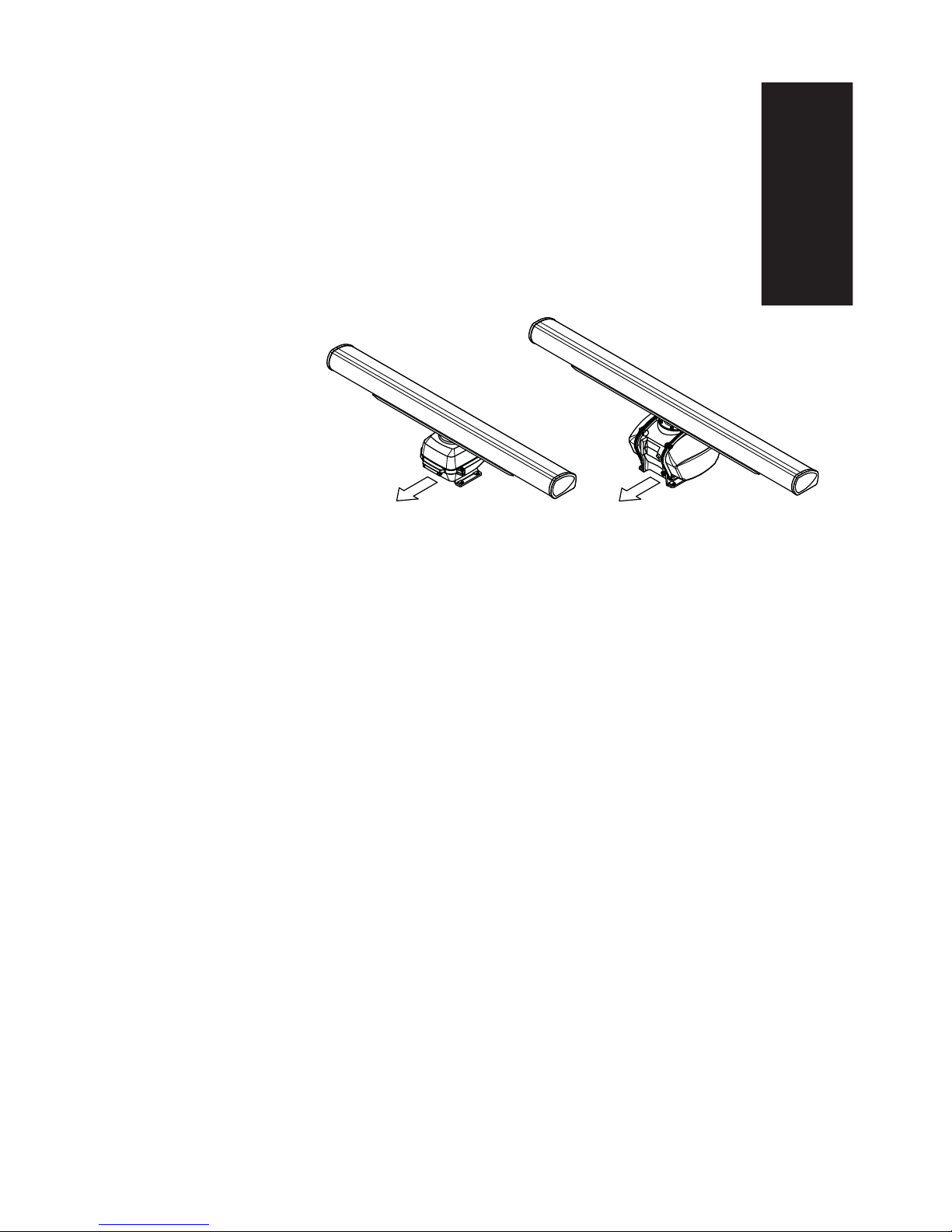
Note: In correct orientation, both the 10 kW and 25kW scanners have the scanner cable exit-
ing towards the stern of vessel.
Page 16

12 |
Wiring |10kW and 25kW Installation Manual
Wiring
Guidelines
When wiring the radar:
• DON’T make sharp bends in the cables
• DON’T run cables in a way that allows water to ow down on to the connectors
• DON’T allow the scanner cable to place pressure on the radar processor connector
But:
• DO make drip and service loops
• DO use cable ties to keep the cables tidy and secure
• DO seal and protect all wiring connections if cables are shortened, lengthened, or re-
terminated
• DO leave room to easily access, install and remove cables
• DO make sure cables connecting to the radar processor are not under stress from bending or
twisting that could place pressure on the processors connectors
Radar scanner: 10 kW
Fitting the scanner cable
1. Unscrew the four cover bolts and lift up the hinged cover of the pedestal.
2. Remove the cable gland assembly from the lower half of the pedestal cover.
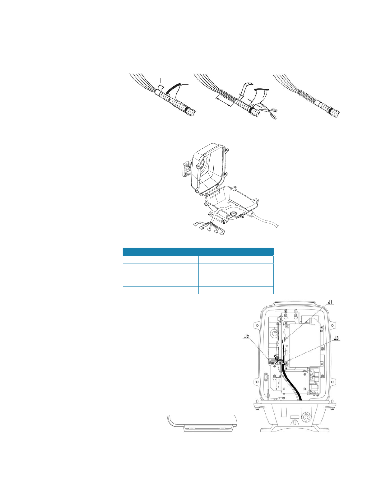
3. Pass the scanner end of the scanner cable through the cable gland (1), plain washer (2), rubber
gasket (3) and another plain washer (4), in the order shown.
4. Unravel the braided shield and wrap it around the washer (4).
4
Page 17
| 13
Wiring | 10kW and 25kW Installation Manual
5. Carefully unwrap the copper tape (1) and black PVC tape (2). Shorten
both the foil shield (3) and the clear insulation material (4) so that an extra
50mm of cable is exposed. Re-use the copper tape on the end of the foil,
ensuring it is stuck to the same side as before, to ensure good conductivity.
ggy
1
2
3
4
50mm
6. Pass the scanner cable through the cable gland opening, into the pedestal.
7. Connect the ve scanner cable connectors to the ‘J’ connectors as follows:
Cable Connector Pedestal Connector (on PCB)
P1 J1
P2 J2
P3 J3
P4 J4
P5 J5
8. Use the cable clamp (1) to secure the cable to the upper housing. The clamp should hold the
cable at the point where it is wrapped in copper tape.
Page 18

14 |
Wiring |10kW and 25kW Installation Manual
9. In the lower half of the housing, secure the cable under the cable clamp. The cable should
have enough slack to not interfere with opening or closing of the case.
10. Fit the cable gland assembly. Use silicon sealant around the cable entry point.
11. Use silicon sealant around the mounting bolts
12. Close the pedestal and rmly secure it with the screws.
Earth the 10 kW scanner
The earth point must be connected to the vessel’s ground system.
1. Connect one end of the copper Earth strop (2) to the bolt (1) on the pedestal.
2. Connect the other end of the Earth strop to the mounting location using the Earth bolt (3).
3. Apply silicon sealant around both of the bolts.
Note: If the radar mounting location is not made of a electrically conductive material, t a
longer earth strap that allows direct connection to the vessel’s ground.
Page 19

| 15
Wiring | 10kW and 25kW Installation Manual
Radar scanner: 25 kW
Fitting the scanner cable
1. Unscrew the four cover bolts and lift up the hinged cover of the pedestal.
2. Remove the cable gland assembly from the lower half of the pedestal.
3. Pass the scanner end of the radar cable through the cable gland (1), plain washer (2), rubber
gasket (3) and another plain washer (4), in the order shown.
4. Unravel the braided shield and wrap it around the washer (4).
5. Pass the scanner cable through the cable gland opening, into the pedestal.
Page 20

16 |
Wiring |10kW and 25kW Installation Manual
6. Connect the ve scanner cable connectors to the ‘J’ connectors as follows:
Cable Connector Pedestal Connector (on PCB)
P1 J1
P2 J2
P3 J3
P4 J4
P5 J5
7. Use the cable clamp (1) to secure the cable to the upper housing. The clamp should hold the
cable at the point where it is wrapped in copper tape.
8. Close the pedestal case sides, securing them with the supplied screws.
9. Fit the cable gland assembly. Use silicon sealant around the cable entry point.
10. Use silicon sealant around the mounting bolts
Page 21

| 17
Wiring | 10kW and 25kW Installation Manual
Earth the 25 kW scanner
The earth point must be connected to the vessel’s ground system.
1. Connect the earth strap (A) to the pedestal with a hexagonal bolt (C).
2. Connect the other end of copper Earth strap to the mounting location, using the special
hexagonal Earth bolt (B)
3. apply silicon sealant around both the bolts.
Note: If the radar mounting location is not made of a electrically conductive material, t a
longer earth strop that allows direct connection to the vessel’s ground.
Page 22
18 |
Wiring |10kW and 25kW Installation Manual
Radar processor connections
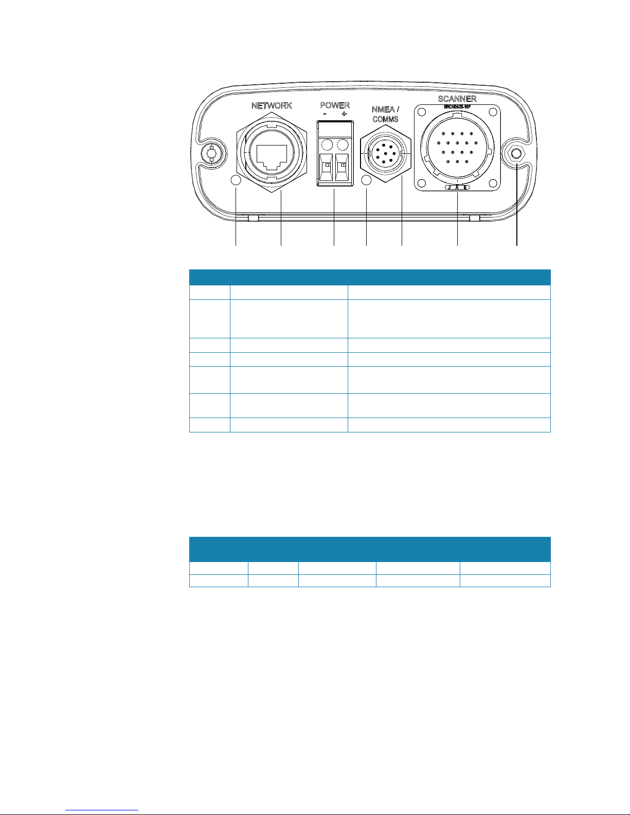
12 345 6 7
Key Name Description
1
LED (Ethernet) Displays status of the Ethernet network connection
2
Network For Ethernet network connection to Simrad
Multifunction displays.
RJ45-Yellow Ethernet adapter cable is supplied.
3
Power (+ve and -ve) Connects to ship’s power - must be 24 V DC
4
LED (Power) Displays power status - illuminated = ON
5
NMEA / Coms NMEA 0183 input for compass.
SimNet or NMEA 2000 Heading via AT10HD
6
Scanner Connects to scanner, providing power and 2-way
communication.
7
Grounding point Connection point to vessel ground
Connect the scanner cable
Connect the large metal plug on the scanner cable to the scanner socket on the processor.
Once inserted, screw on the locking collar by hand. The connector is keyed, preventing
incorrect orientation.
Connect the power cable
The radar processor requires a 24 V DC supply capable of delivering 15 amps continuous.
Scanner Fuse rating Cable length 5 m
(16.4 ft)
Cable length 10 m
(26 ft)
Cable length 20m
(20 ft)
10 kW 15 A 2.5mm (14 AWG) 6mm (10 AWG) 10mm (8 AWG)
25 kW 15 A 2.5mm (14 AWG) 6mm (10 AWG) 10mm (8 AWG)
The radar processor must be connected to a dedicated fuse/circuit breaker. The fuse/circuit
break
er should be labeled accordingly.
To connect the power cable to the radar processor, you must:
1. Strip away approximately 0.4” (10 mm) of the insulation at the end of each core of the power
cable
2. Unscrew the small retention screw from the positive input connector (identi ed by the + sign)
on the radar processor
3. Insert the bare end of the positive wire into the positive power cable input connector to make
a connection
4. Tighten the small holding screw to hold the positive wire in place. Gently pull on the positive
wire to ensure that it is secured
5. Repeat this process to connect the negative wire to the negative power cable input connector
(identi ed by the – sign)
Page 23
| 19
Wiring | 10kW and 25kW Installation Manual
Connect the ground wire
The radar processor has a chassis ground connection stud located on the far right hand side
of the unit. The chassis ground is DC isolated from power (–ve) to eliminate the risk of galvanic
corrosion.
If you are installing the radar processor on a vessel with a metal hull, connect the radar
processor chassis ground to the hull at the closest possible location, using 12 AWG wire (or
thicker):
Connect the Ethernet cable
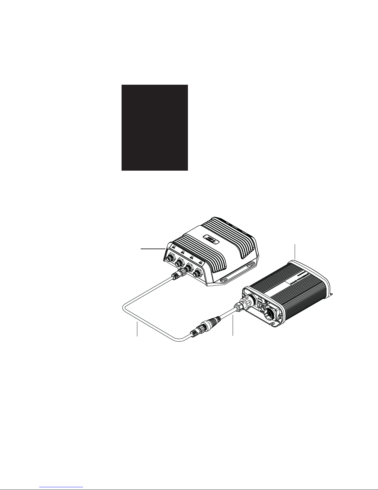
Ethernet is used to share the radar data with compatible displays on the network. Use of a
adaptor is required to convert from RJ45 connector to the 5 pin connector used on Simrad
network hubs and displays.
1
32
4
1 Radar processor
2 Ethernet adapter cable RJ45 - 5 Pin Yellow (Included)
3 5 pin yellow ethernet cable
4 NEP-2 or other Navico ethernet device
Page 24
20 |
Wiring |10kW and 25kW Installation Manual
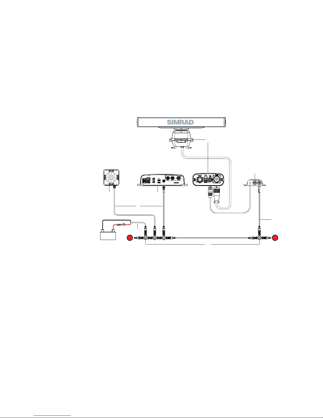
Connect the NMEA/Comms cable (Heading)
A heading sensor is required for the following functionality;
• MARPA : heading at 10hz or faster is required for the radar processor. Heading must also be
connected to the display.
• Radar Chart overlay: heading is required by the display to correctly overlay the radar over a
chart.
• North Up: For the display to show the radar page with the top of the PPI as north.
The radar processor input (labeled NMEA / COMMS) is compatible with a NMEA 0183 heading
sensor.
For heading sensors that output NMEA 2000 PGNs or SimNet, an AT10HD must be used to
convert PGNS to NMEA0183 @ 4800 baud
Heading calibration should be performed during initial setup, annually, and after any major
structural changes to the vessel.
+
_
12 V DC
T
T
2
1
6
7
8
5
43
1 Radar system
2 AT10HD NMEA 2000 / NMEA 0183 high speed heading converter
3 NMEA 2000 compliant heading sensor
4 Compatible MFD with display
5 Micro-C drop cables
6 Network power 12 V DC
7 Micro-C backbone (NMEA 2000) with terminators
8 Micro-C to SimNet adapter cable
Note: the Micro-C backbone requires 12 V DC, and should therefore not be connected di-
rectly to the radar pocessor power supply which is 24 V DC.
Con guration on display
Final setup steps such as bearing alignment, and scanner height need to be done on the
display MFD. Refer to the display installation manual for further details.
Page 25

| 21
Pinouts | 10kW and 25kW Installation Manual
Pinouts
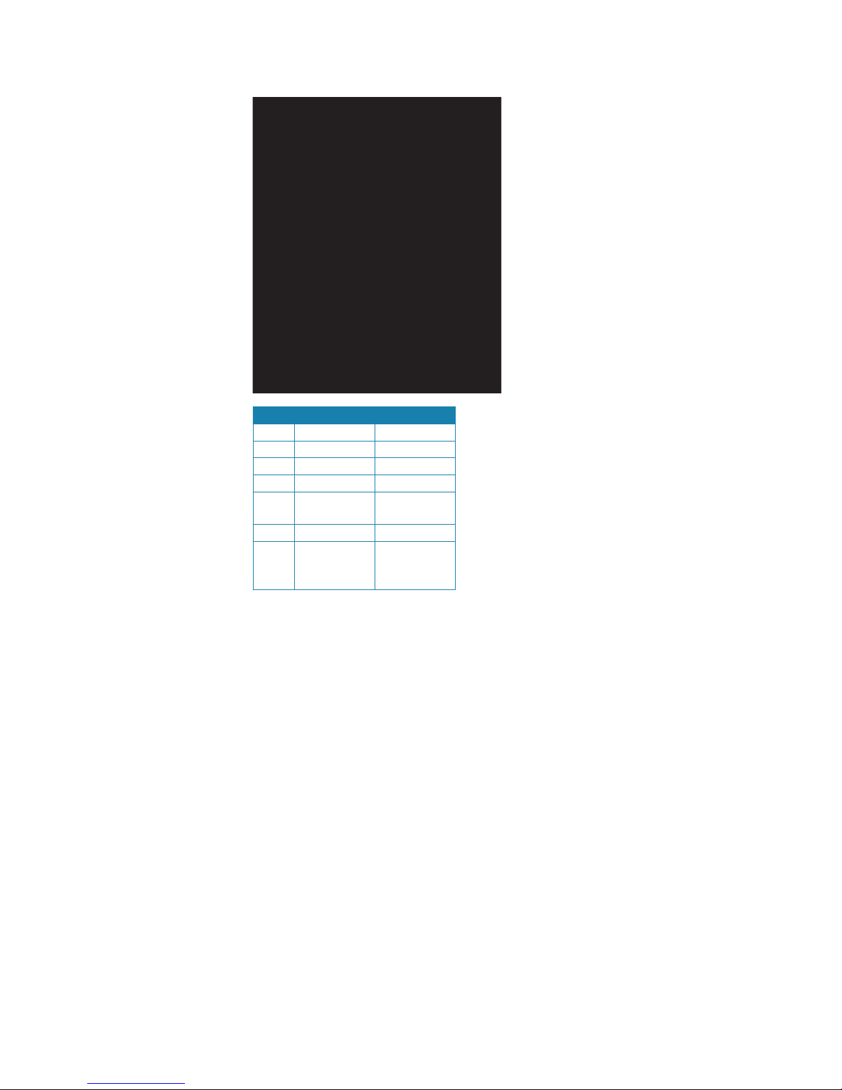
Scanner cable
Pin Color/Name
AWG
Size
P2 P1 P3 P4 P5 Purpose
1 Blue / Gray (thick) #16 1 Motor Ground
2
Purple / Brown (thick) #16 1 Motor Ground
3 White / Orange (thick) #16 2 Motor Power
4 Red / Green (thick) #16 2 Motor Power
5 Black / Sky (thick) #16 1 Scanner
Ground
6 Black #22 6 Analog
Ground
7 Drain wire (coax line) #24 2 Video Ground
8 No connection Not used
9 Yellow / Pink (thick) #16 Scanner Power
10 Axis line (transparent
insulation)
#24 1 Video
11 Yellow (thin) #24 3 2 RS-485
Comm+
12 Green (thin) #24 5 Bearing Zero
13 White (thin) #24 4 RS-485 Comm14 Drain wire #24 2 Trigger
Ground
15 Shield line #24 1 Trigger
16 Orange (medium) #22 3 Bearing Pulse
Shell Braid shield Shield
5
Page 26
22 |
Pinouts |10kW and 25kW Installation Manual
NMEA / COMMS cable
Pin Function Color
1 NMEA RX A Green
2 NMEA RX B Red
7 NMEA TX A Orange
8 NMEA TX B Blue
12 NMEA TX
GROUND
Yellow
9 SHIELD Drain
10 RADAR
REMOTE
POWER IN
Brown
Note: the NMEA/COMMS cable is an optional cable (part number: AA010070) for installations
using a NMEA 0183 heading sensor.
Page 27

| 23
Speci cations | 10kW and 25kW Installation Manual
Speci cations
TXL-10S-4/TXL-10S-6
Type of emission PON - Passed FCC/IC/R&TTE Type Certi cation:
FCC ID: CKENKE2103
IC ID: 768C-NKE2103
R&TTE: Tele cation CE0560
Ambient conditions According to IEC60945-4
Operating Temperature: -25 to +55°C
Relative humidity: +40°C, 93% RH
Vibration:
Amplitude 2 to 13.2Hz, +/-1mm +/- 10%
Amplitude 13.2 to 100Hz,
Gravity acceleration 7m/sec2
Waterproof:IPX6
Relative wind velocity 51.5 m/sec (100 Knots)
Power consumption 230W (Max.) in maximum wind velocity
DC input 21.6 to 31.2 V (DC24 Volt Systems)
Pre-heating time Minimum 90 sec
Outside dimensions Height 458mm x Swing Circle Diameter 1320mm (4 ft)
Height 458mm x Swing Circle Diameter 1910mm (6 ft)
Mass 34kg+/-10% (4ft) / 36kg+/-10% (6ft)
Plane of polarization Horizontal Polarization
Beam width Horizontal 1.8°+/-10% (4ft, -3dB width)
Horizontal 1.2°+/-10% (6ft, -3dB width)
Vertical 20° +20% (4/6ft, -3dB width)
Side lobe level Below -26dB max. (4/6ft, within ±10°)
Below -30dB max. (4/6ft, outside ±10°)
Rotation 27 rpm (4/6ft, Min 20rpm at Max 100Knots)
Transmitter frequency 9410±30MHz
Peak power output 10kW±50% under any pulse condition
Transmitter tube Magnetron NJRC Model MAF1565N
Pulse length/Pulse Repetition
Frequency
0.08µS+/-30%/2250Hz +/-5%
0.25µS+/-25%/1700Hz +/-5%
0.50µS+/-25%/1200Hz+/-5%
0.80µS+/-25%/750Hz+/-5%
1.0µS+/-25%/650Hz+/-5
Duplexer Circulator H-6AJRD00001 FCX-68 and Diode Limiter NJS6930
Mixer MIC front-end - Model NJT1969
IF ampli er Center frequency: 60MHz +/-3MHz
Bandwidth:
20MHz +/-3MHz (0.08µS)
6MHz +/ -2MHz(0.25µS, 0.5µS)
3MHz +/-1MHz (0.8µS, 1.0µS)
Gain: 90dB min.
Characteristic: Log
Output: -2V for 100dB typical
Bandwidth controlled by serial port
Noise gure NJT1969 @ 6dB (Average) at front-end input.
Com Port RS485 9600bps Half Duplex
Propriety Digital COM Speci cation
Standard scanner cable length 20m (packed in carton)
Maximum allowable scanner cable
length
30m
6
Page 28

24 |
Speci cations |10kW and 25kW Installation Manual
TXL-25S-7
Type of emission PON - Passed FCC/IC/R&TTE Type Certi cation:
FCC ID: CKENKE2254
IC ID: 768C-NKE2254
R&TTE: Tele cation CE0560
Ambient conditions According to IEC60945-4
Operating Temperature: -25 to +55°C
Relative humidity: +40°C, 93% RH
Vibration:
Amplitude 2 to 13.2Hz, +/-1mm +/- 10%
Amplitude 13.2 to 100Hz,
Gravity acceleration 7m/sec2
Waterproof:IPX6
Relative wind velocity 51.5 m/sec (100 Knots)
Power consumption 240W (Max.) in maximum wind velocity
DC input 21.6 to 31.2 V (DC 24 Volt Systems)
Pre-heating time Minimum 180 sec
Outside dimensions Height 536mm x Swing Circle Diameter 2270mm
Mass 58kg+/-10%
Plane of polarization Horizontal Polarization
Beam width Horizontal 1.0°+/-10% (-3dB width)
Vertical 20° +20% (-3dB width)
Side lobe level Below -26dB max. (within ±10°)
Below -30dB max. (outside ±10°)
Rotation 24 rpm (Min 20rpm at Max 100Knots)
Transmitter frequency 9410±30MHz
Peak power output 25kW±50% under any pulse condition
Transmitter tube Magnetron NJRC Model M1568BS
Pulse length/Pulse Repetition
Frequency
0.07µS+/-30%/2250Hz +/-5%
0.20µS+/-25%/2250Hz +/-5%
0.30µS+/-25%/1900Hz+/-5%
0.40µS+/-25%/1400Hz+/-5%
0.80µS+/-25%/750Hz+/-5%
1.0µS+/-25%/650Hz+/-5%
1.2µS+/-25%/510Hz+/-5%
Duplexer Circulator NJC3901M and Diode Limiter NJS6930
Mixer MIC front-end NRG-162
IF ampli er Center frequency: 60MHz +/-3MHz
Bandwidth:
25MHz +/-3MHz (0.07µS)
8MHz +/ -2MHz(0.2µS, 0.3µS, 0.4µS)
3MHz +/-1MHz (0.8µS, 1.0µS, 1.2µS)
Gain: 90dB min.
Characteristic: Log
Output: -2V for 100dB Typical
Bandwidth controlled by serial port
Noise gure 7.5dB (Average)
Com Port RS485 9600bps Half Duplex
Propriety Digital COM Speci cation
Standard scanner cable length 20m (packed in carton)
Maximum allowable scanner cable
length
30m
Page 29
| 25
Drawings | 10kW and 25kW Installation Manual
Drawings
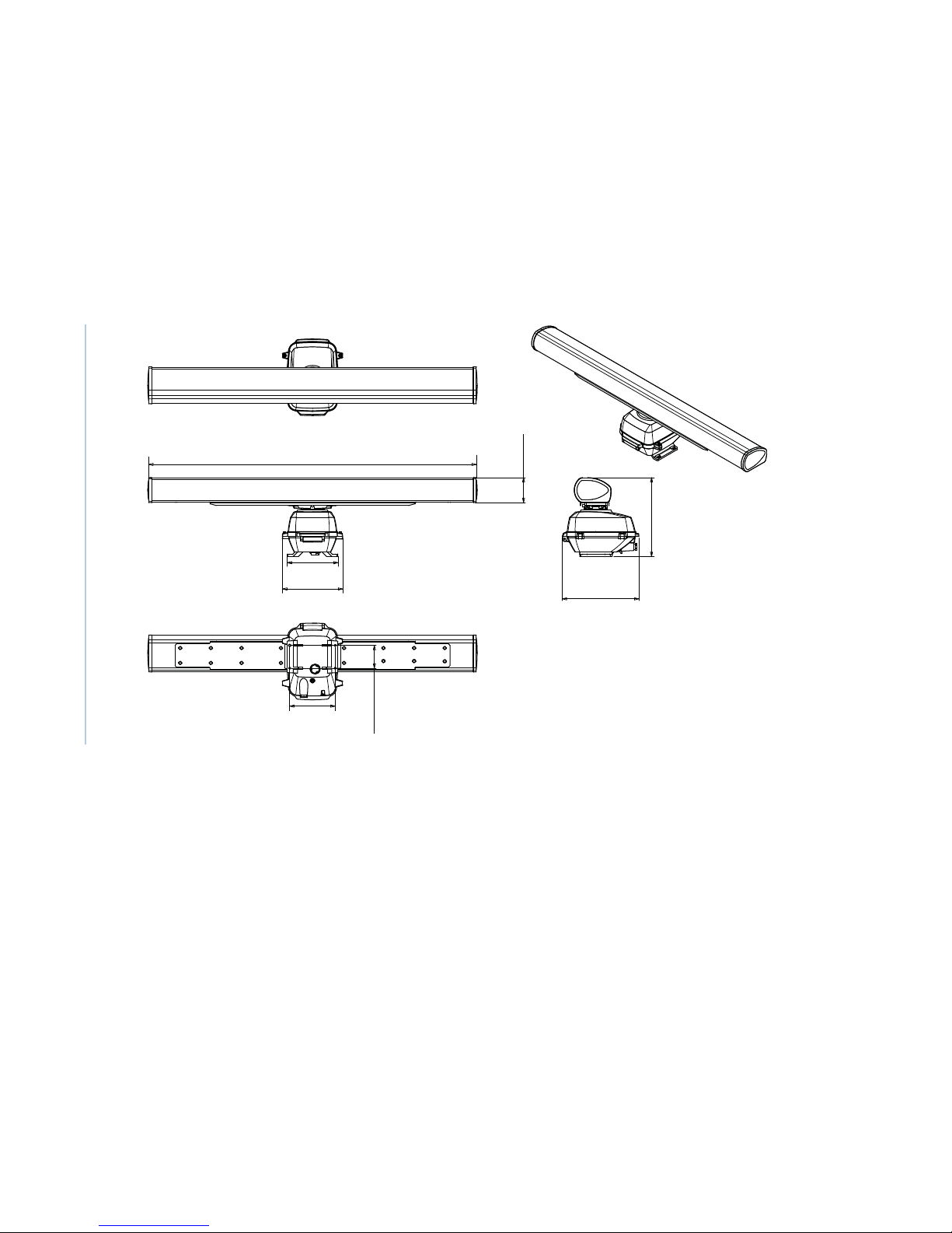
10 kW scanner
4 FT: 1285mm (50.59”) 6 FT: 1880 mm (74.02”)
348 mm (13.70”)
290 mm (11.42”)
141.7 mm
(5.58”)
457.4 mm
(18.01”)
461 mm
(18.15”)
260 mm
(10.24”)
130 mm
(5.12”)
Note: mounting templates are provided.
Page 30
26 |
Drawings |10kW and 25kW Installation Manual
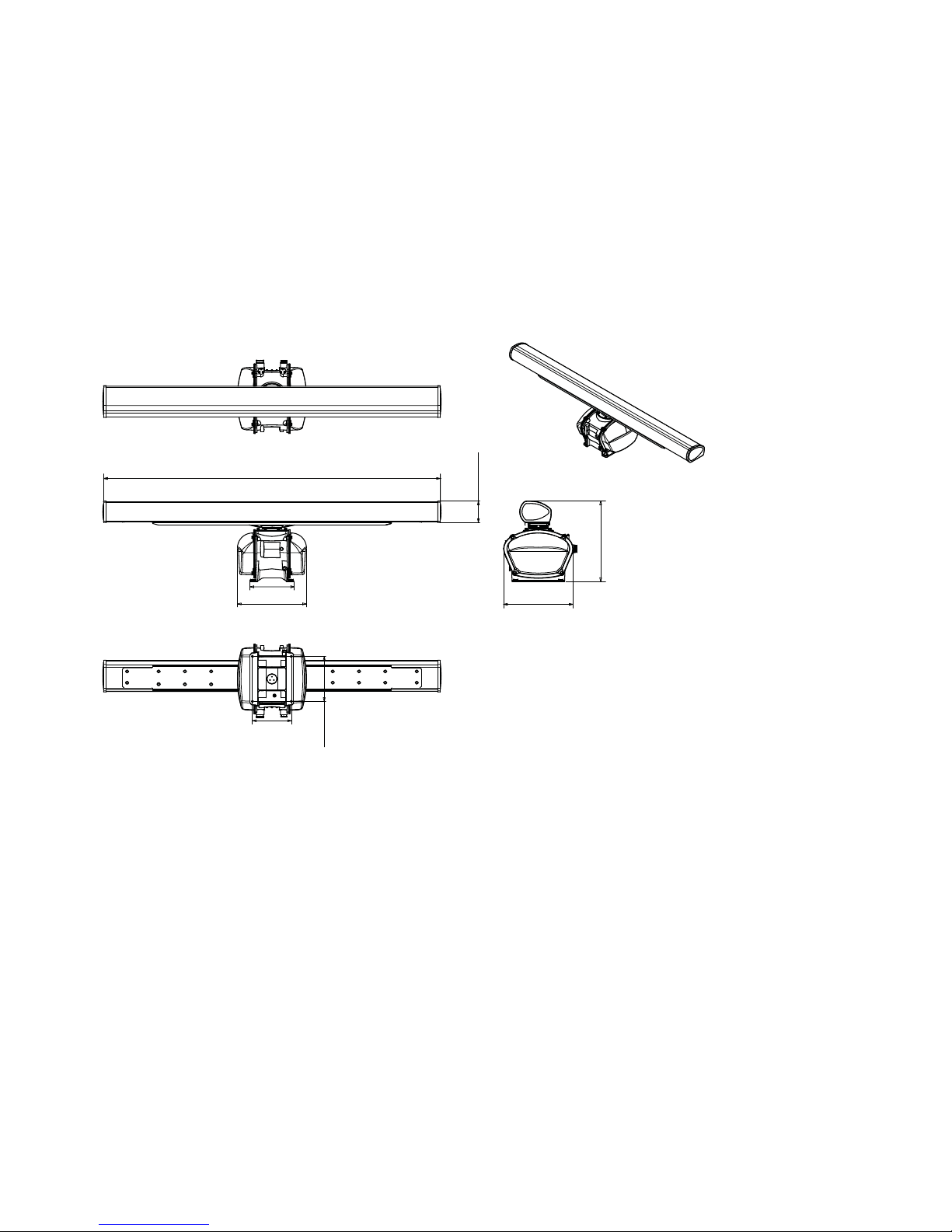
25 kW scanner
2254 mm (88.74”)
458 mm (18.03”)
260 mm
(10.24”)
300 mm
(11.81”)
142 mm
(5.59”)
536 mm
(21.10”)
463 mm
(18.23”)
290 mm (11.42”)
Note: mounting templates are provided.
Page 31
| 27
Drawings | 10kW and 25kW Installation Manual
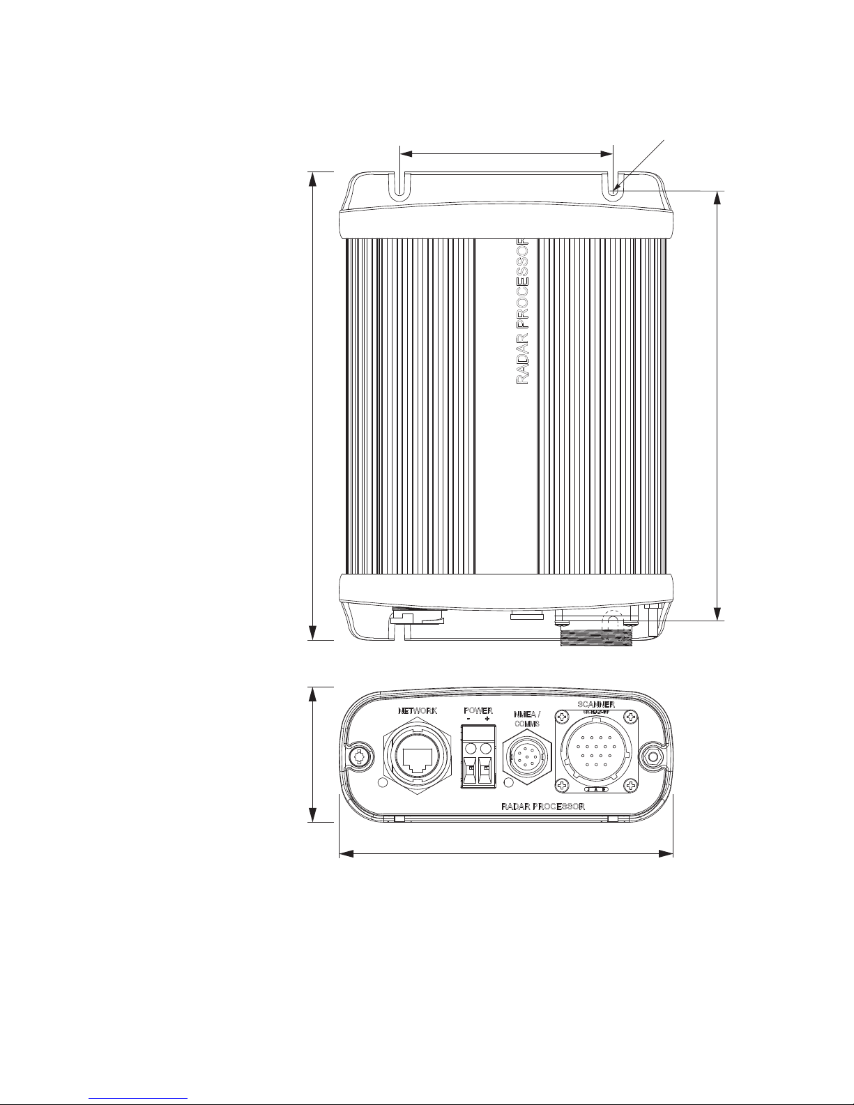
Radar processor
197.5 mm (7.77")
182.6 mm (7.19")
90.4 mm (3.56")
ø: 4 mm (3.56")
141 mm (5.55")
57.1 mm (2.25")
 Loading...