

Page 1

Simrad SD570
Fishery sonar
Installation manual
A L W A Y S A T T H E F O R E F R O N T O F T E C H N O L O G Y
www.simrad.com
Page 2

Page 3

Simrad SD570
Fishery sonar
Installation manual
851--160085 / Rev.B
Page 4

Note
Simrad AS makes every effort to ensure that the information contained within this
document is correct. However, our equipment is continuously being improved and
updated, so we cannot assume liability for any errors which may occur.
Warning
The equipment to which this manual applies must only be used for the purpose for
which it was designed. Improper use or maintenance may cause damage to the
equipment or injury to personnel. The user must be familiar with the contents of the
appropriate manuals before attempting to operate or work on the equipment.
Simrad AS disclaims any responsibility for damage or injury caused by improper
installation, use or maintenance of the equipment.
Copyright
E 2004 Simrad AS
ISBN 82-8066-018-6
The information contained within this document remains the sole property of Simrad
AS. No part of this document may be copied or reproduced in any form or by any
means, and the information contained within is not to be communicated to a third party,
without the prior written consent of Simrad AS.
Support
For support on your Simrad equipment, consult your local dealer, visit
www.simrad.com, or contact us directly at support.fish@simrad.com.
Simrad AS
Strandpromenaden 50
Box 111
N-3191 Horten
Telephone: +47 33 03 40 00
Facsimile: +47 33 04 29 87
M A X I M I Z I N G Y O U R P E R F O R M A N C E A T S E A
Page 5

Installation manual
1
851-160085 /B
Sections
This book is the Installation manual for the SD570 fishery sonar. It describes how to
install the various units used by the SD570 system.
1Introduction
This section gives a brief description of the SD 570/SE 570 sonars and the
installation requirements.
2 Installation procedures
Thissectionprovidesthenecessaryinformationfortheinstallationandcabling
of the complete sonar system according to Simrad’s requirements.
3 Start-up procedures
This sectioncontains the start-up procedures to be carried out after the
installation of the sonar.
4 Trunk systems
This sectiondescribes the differenttrunk systemsthat can be used with the SD
570/SE570 Hull Unit. Also described are the adapter flanges which must be
used if the Hull Unit is to be installed into alreadyinstalled SQ4, SQ, SB2 and
SK3 trunks.
5Drawings
6 Appendices
Page 6

Simrad SD570
2
851-160085 / B
Remarks
References
Further information about the SD570 system may be found in the following manuals:
• SD570 Operator manual
The reader
This Installation manual is intended for the design and installation engineers at the
shipyard performing the installation. The information is supplied as the basis for the
shipyard’s own installation drawings applicable to the vessel. On completion of the
installation, this manual must be kept on the vessel for reference purposes during
system maintenance.
Note
This manual includes sections that may be revised individually. In the event of a
revision to any part of this manual, this “Cover and Contents” section will be replaced.
Page 7
Installation manual
3
851-160085 / B
Document revisions
Rev Written by
Checked by Approved by
Date Sign Date Sign Date Sign
A Unknown CL
B 02.02.04 RBr 02.02.04 EGj 02.02.04 ESB
Sect Title Revision File
0 Cover and contents B 851--160085
1 Introduction B 851--160115
2 Installation procedures B 851--160116
3
4
5
6
Start--up procedures
Trunk syst em
Drawings
Appendices
B
B
B
B
851--160117
851--160503
851--160118
851--160675
Rev.A First edition.
Rev.B Re--issued. All sections updated to Rev.B, but product specific informa-
tion has not been changed. ISBN number issued.
Page 8

Simrad SD570
4
851-160085 / B
Blank page
Page 9
Installation manual
I
851-160085 / B
High voltage safety warning
Precautionary measures
The voltages used to power this equipment
are potentially lethal. Even 110 volts can kill.
Whenever possible, the following
precautionary measures must be taken before
any work is carried out inside the equipment:
S Switch off all high-voltage power supplies.
S Check the operation of any door interlocks
and any other safety devices.
S Completely discharge all high-voltage
capacitors.
It should be noted that interlocks and safety
devices are normally located only at regular
access points, and high voltages may be
exposed during dismantling.
Never work alone on high-voltage
equipment!
First aid in the event of
electric shock
Normally, even a high voltage electric shock
will not kill instantly. The victim can still be
revived even when his breathing and
heart-beat have ceased.
Could YOU save someone’s life?
In the event of electric shock, the correct
actions, performed quickly may well save the
victim’s life. Make sure you know what to
do!
Immediate action
While shouting for help, remove the source of
power from the victim. Switch off the supply
if possible, or using a dry, non-conductive
material (rubber gloves, broom handle etc.) to
insulate yourself, separate the victim from the
source. If the voltage exceeds 1000 volts,
switch off the supply and be ready to catch
the victim. Take care- do not become a victim
yourself.
Commence first aid on the spot. Continue to
shout for assistance till someone arrives.
1 Lay the victim flat on his back and loosen
any tight clothing (collar, tie, belt etc.).
2 Open his mouth and check for and remove
any false teeth, chewing gum etc.
3 Check if the victim is breathing. If not,
check if his heart is beating. The pulse is
normally easily found in the main arteries
of the neck, either side of the throat, up
under the chin.
If his heart is beating but he is not breathing,
commence artificial respiration. If the
victim’s heart is not beating, commence
external cardiac massage (ECM). Continue to
shout for assistance till someone arrives.
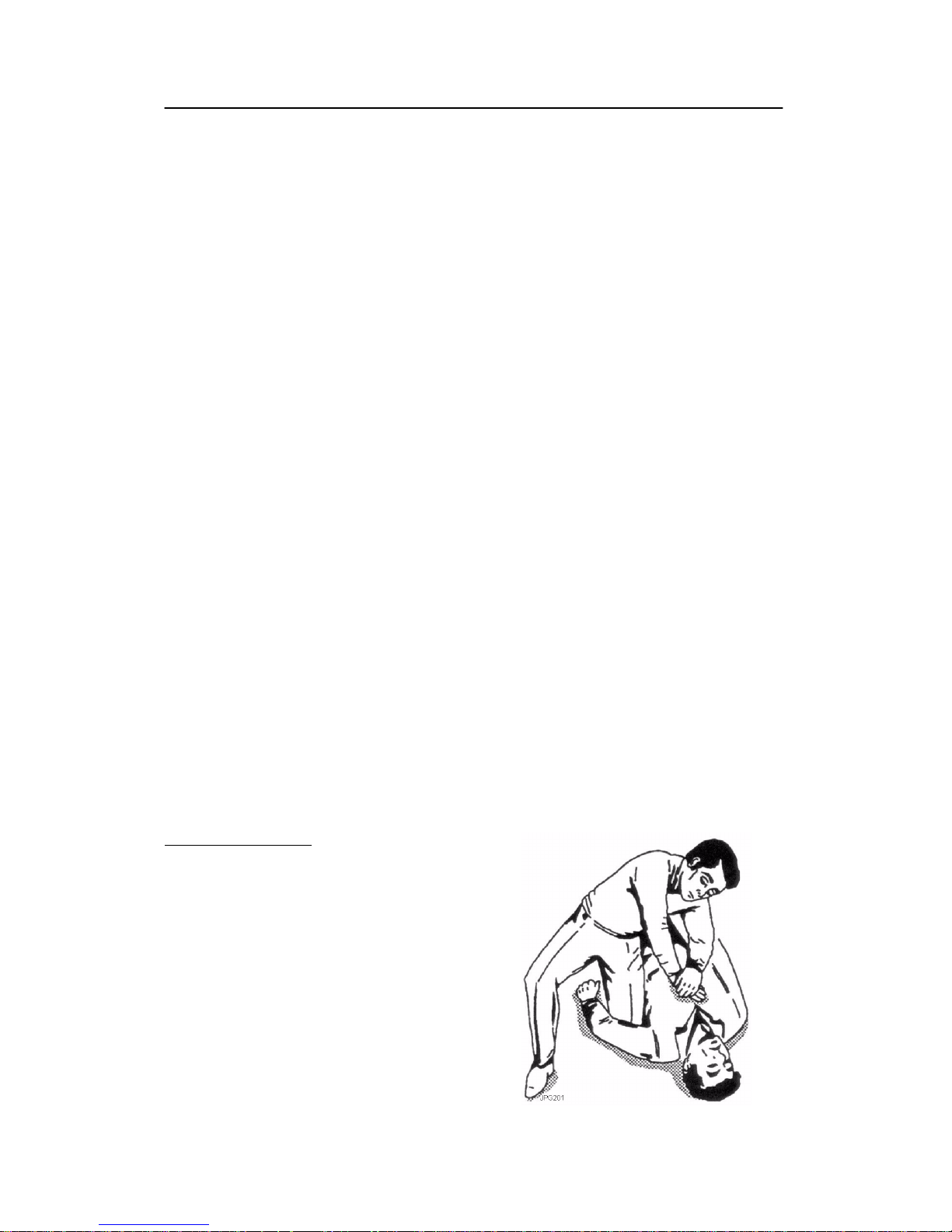
External cardiac massage
1 Kneel beside the victim. Place the heel of
one hand in the centre of his chest, at a
position half way between the notch
between the collar-bones at the top of his
chest, and the dip i n the breast-bone at the
base of his rib cage. Place the other hand
on top of the first.
2 Keeping the arms straight and using your
entire weight, press down rapidly so that
the breast bone is depressed four- five cm,
then release the pressure. Repeat
rhythmically at a rate of one cycle per
second. This will be hard work, but keep
going. His life depends on YOU. Do not
worry about breaking his ribs - these will
heal if he survives.
Page 10
Simrad SD570
II
851-160085 / B
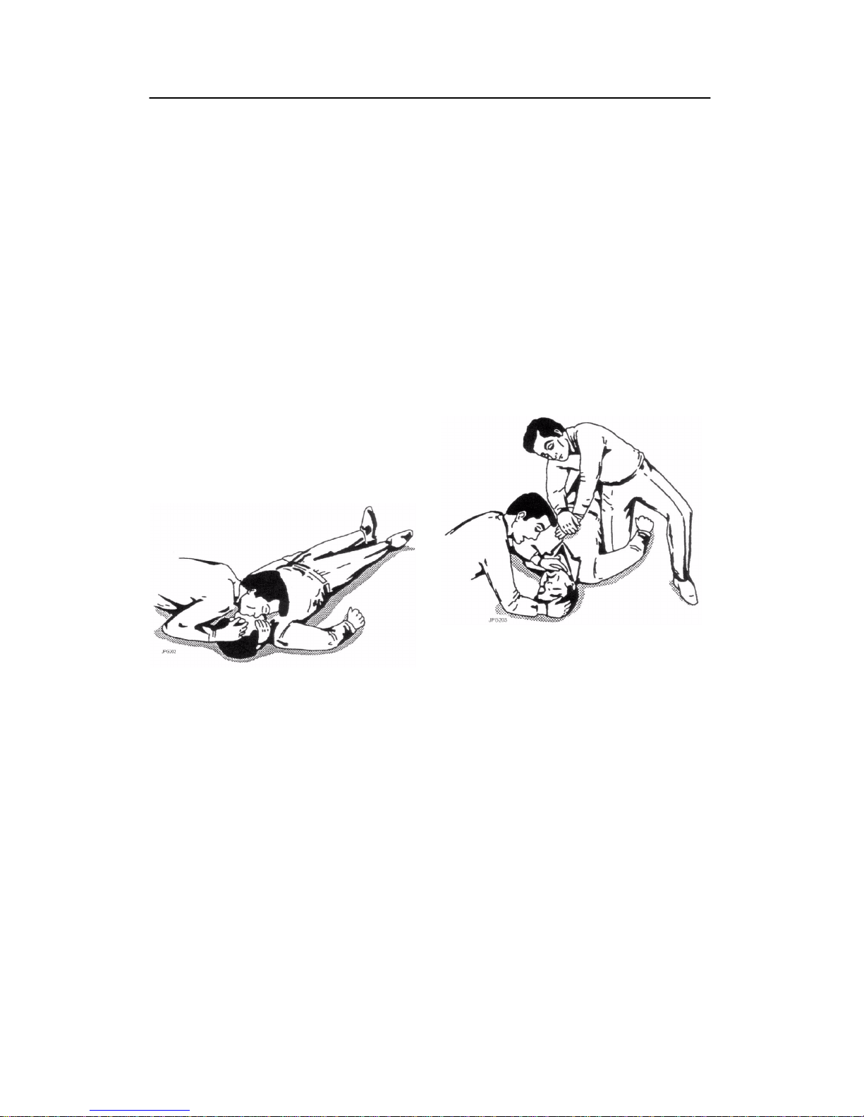
Artificial respiration
1 Kneel besides the victim’s head. Place one
hand under his neck and lift, allowing his
head to fall back. This will lift his tongue
and open the air passage in his throat.
2 Place the palm of the hand on his forehead
to maintain the ”chin-up” position.
3 Using the index finger and thumb of the
same hand, pinch the victim’s nostrils
closed. Open his mouth.
4 Take a deep breath and cover his mouth
with yours. Blow steadily into his lungs to
expand his chest. Remove your mouth
from his to allow the air t o escape from his
chest. You should be able to see his chest
deflate.
5 Repeat the ”inflation-deflation” cycle at a
rate of about 12 cycles per minute till the
victim begins to breath normally again.
Combining ECM and artificial
respiration
If you are alone, perform one cycle of
artificial respiration for every five cycles of
ECM. This will be hard work, but keep going.
His life depends on you!
If there are other people available to help, one
should perform the ECM while one performs
the artificial respiration for every five cycles
of ECM. It will be much more efficient with
two people.
Once the victim’s heart is beating and he is
breathing, roll him onto his side and support
him in that position. As consciousness returns
he may vomit, and this will allow any liquid
to drain out of his mouth.
Remove the victim to a hospital as soon as
possible, but do not interrupt the artificial
respiration and ECM cycles till his heart beat
and breathing returns.
If started quickly and performed correctly, the
resuscitation methods described will keep a
sufficient volume of oxygenated blood
flowing trough the victims body to allow full
recovery.
Proficiency i n the resuscitation methods can
only be achieved trough training. All
personnel concerned should attend courses on
a regular basis. Remember, someone’s life
could depend on you.
Do you know what to do?
Page 11

Introduction
I
851--160115 / B
851- 160115 / AA000 / 3- 11
Introduction
This section gives a brief description of the
SD 570 / SE 570 sonars and the installation
requirements.
Page 12

Simrad SD570 / Base version
II
851--160115 / B
Document revisions
Rev Date Written by Checked by Approved by
A Unknown
B 03.01.01 RBr ESB RBr
C
D
(The original signatures are recorded in the company’s logistic database)
Page 13

Introduction
III
851--160115 / B
Table of contents
1 INSTALLATION DOCUMENT 1..................................
2 SUPPLY CONDITIONS 2.......................................
2.1 General 2.....................................................
2.2 Main units 2..................................................
2.3 Options 2.....................................................
2.4 Installation procedures 5.......................................
2.5 Equipment responsibility 5.....................................
2.6 Receipt, unpacking and storage 5................................
3 GENERAL REQUIREMENTS 7..................................
3.1 Responsibility and approbation 7................................
3.2 Compass deviation 7...........................................
3.3 Noise sources 7...............................................
3.4 Docking 7....................................................
3.5 Cabling 7.....................................................
3.6 Auxiliary equipment 8.........................................
3.7 Technical specifications 9.......................................
3.8 Weights and dimensions 10......................................
Page 14

Simrad SD570 / Base version
IV
851--160115 / B
Document history
(The information on this page is for internal use)
Rev.A Original issue for Base version.
Rev.B Document transferred to Interleaf. No changes made to text or illustra-
tions.
Page 15

Introduction
1
851--160115 / B
1 INSTALLATION DOCUMENT
This installation manual will act as an installation document for
later updating and service on the sonar, and must therefore be
stored on board the vessel into which the equipment is to be
installed.
To ensure the best possible result of the installation, it is important
that each procedure is carefully followed. Each listed procedure
comprises squares for t icking off while proceeding in the
procedure. In addition to be a sign that the procedure is followed,
this will also be a good guidance for the installer.
Note that the installer becomes fully responsible for the
equipment during the installation, and that the guarantee only is
covered when the installation is made in full accordance with this
installation manual.
Page 16

Simrad SD570 / Base version
2
851--160115 / B
2 SUPPLY CONDITIONS
2.1 General
This manual describes the installation for both the SD 570 and the
SE 570 sonars. The only difference between these sonars is the
angle to which the transducer can be tilted. The SD 570
transducer can be tilted to - 90_, while the SE 570 transducer is
limited to - 45_. All units for the SD 570 and SE 570 have the same
physical size.
The Hull Unit uses an installation trunk which is equal to the old
Simrad SL and SX installation trunks. The Hull Unit can therefore
easily be mounted in an old SL or SX trunk. As an option, an
adapter flange can be delivered for mounting the Hull Unit in an
old SK, SB or SQ trunk. Note that the trunk is not included in the
standard delivery, but can be ordered as an option (see chapter 2.3
Options ).
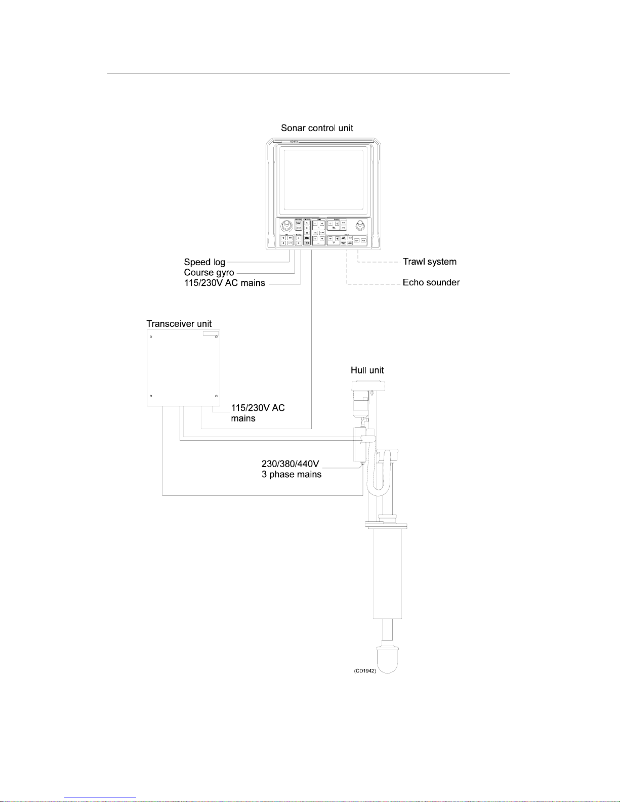
2.2 Main units
The standard SD 570 Sonar system comprises the following main
units:
Simrad SD 570 Sonar Control Unit SD5- 112629..............
Simrad SD 570 Transceiver Unit SD5- 112630................
Simrad SD 570 Hull Unit SD5- 112631.......................
The standard SE 570 Sonar system comprises the following main
units:
Simrad SE 570 Sonar Control Unit SE5- 112898...............
Simrad SE 570 Transceiver Unit SE5- 112899.................
Simrad SE 570 Hull Unit SE5- 112900.......................
A diagram of the standard sonar system is shown in figure 1.
2.3 Options
The installation trunk can be made by the shipyard (refer to
drawing in section “Trunksystems” ) or be ordered as an optional
delivery:
Installation trunk with blind cover SD5- 112632..............
For installations in an existing SK, SB or SQ trunk, refer to the
drawings in the section Trunk systems in this manual. The
following adapters with blind covers can be ordered as options:
SQ4 Adapter flange SD5- 112641...........................
Page 17

Introduction
3
851--160115 / B
SQ & SB2 Adapter flange SD5- 112642......................
SK3 Adapter flange SD5- 112643...........................
The cable between the Sonar Control Unit in the wheelhouse and
the Transceiver Unit in the sonar room (see figure 1) can be
delivered with the following lengths:
50- meter interconnection cable 380- 112595..................
75- meter interconnection cable 380- 112596..................
100- meter interconnection cable 380- 112597.................
The interconnection cable has a preconnected connector at the
Sonar Control Unit end.
A system for electronic stabilization of the transducer may be
delivered as an option. If the stabilization system is ordered, the
kit is included in the box for the Sonar Control Unit.
Stabilization system KIT- 113200...........................
Page 18
Simrad SD570 / Base version
4
851--160115 / B
Figure 1 - SD 570 / SE 570 sonar system
Page 19

Introduction
5
851--160115 / B
2.4 Installation procedures
The installation of the standard SD 570 / SE 570 Sonar systems
includes the following stages:
The installation of the standard SP 270 Sonar system includes the
following stages:
• Mounting the Installation Trunk
• Mounting the Hull Unit
• Mounting the Transceiver Unit
• Mounting the Sonar Control Unit
• Cabling
• Start- Up
• Final Test
Refer to the cable plan, the main interconnection diagrams and the
outline dimensions drawings of the units.
2.5 Equipment responsibility
Upon receipt of the equipment, the installation shipyard and/or
the dealer automatically becomes fully responsible for the
equipment unless otherwise is stated in the contract. This
responsibility covers the storage period before the installation, the
actual installation, commissioning, and the period between the
commissioning and the acceptance of the equipment by the end
user (normally the owner of the vessel into which the equipment
is to be installed).
The guarantee period for the system (as specified in the contract)
begins as soon as acceptance documents have been signed, unless
other arrangements have been made in the contract.
2.6 Receipt, unpacking and storage
On receiving the equipment, the shipyard and/or the dealer
should ensure that the delivery is complete and inspect each
container for physical damage. If the inspection at receipt reveals
indication of crushing, dropping, immersion in water or any other
form of damage, the recipient should request a representative
from the carrier to be present during unpacking.
During unpacking, the equipment should be inspected for
physical damage, i.e. broken controls and indicators, dents,
scratches etc.
If damage to the equipment is discovered, the recipient should
notify the carrier and Simrad so that Simrad can arrange for
replacement or repair of the damaged equipment.
Page 20

Simrad SD570 / Base version
6
851--160115 / B
The equipment, once unpacked, must be stored inside in a room
with an atmosphere free from corrosive agents. In addition, the
equipment must be covered to protect it from dust and other
forms of contamination.
Page 21

Introduction
7
851--160115 / B
3 GENERAL REQUIREMENTS
3.1 Responsibility and approbation
The Hull Unit of the sonar is generally approved by The
Norwegian Veritas (Organization for classification and registry of
shipping). An approval of the installation must, however, be
applied for in each case to the local maritime authority.
The ship owner and the shipyard are responsible for the
application.
3.2 Compass deviation
When the installation is finished, the compass must be checked
both with the sonar operative and inoperative. The ship owner
and the skipper are responsible for such a check to be carried out.
3.3 Noise sources
Prior to installation, the vessel’s h ull should be thoroughly
inspected in dock. Roughness on the shell plating surface, and
protruding obstacles are examples of noise-causing elements.
These must be smoothed or removed. Also ensure that the
propeller is not chipped or corroded.
3.4 Docking
When dry docking the vessel, make sure that there is enough
room underneath for installation of the sonar trunk and
protection blister (refer to figures 4 and 5 in section Installation
procedures .
3.5 Cabling
If the cable from the wheelhouse to the sonar room passes through
hatches or places where it may be damaged, it should be run
through a pipe. Note that the cable must not be installed together
with high-power cables, antenna cables etc.
Page 22

Simrad SD570 / Base version
8
851--160115 / B
3.6 Auxiliary equipment
The SD 570/SE 570 sonars require connection of a speed log and
a course gyro. An inaccurate log or gyro input will cause
inaccurate indication of the vessel and target movements.
Speed
log:
• Pulse log: 100, 200 or 400 pulses/nm.
• Serial line, standard NMEA 0183; RS232, RS422 or Current
loop.
Course gyr
o:
• 3- phase synchro signal, 20-220V L- L, 50/60/400 Hz.
Gear ratio 1:360, 1:180, 1:90, 1:36
• 3- phase stepper signal, 20- 220V L- L.
Gear ratio 1:360, 1:180, 1:90, 1:36.
• Serial line, standard NMEA 0183; RS232, RS422 or Current
loop.
Echo
sounder:
In order to get a depth indication on the catch control page on the
sonar, one of the following Simrad echo sounders can be
connected:
• EQ50, EQ55, EQ100, ES60, ES380 series, ES500 (RS232 serial
line).
Traw l
system:
In order to get the trawl information on the sonar display, one of
the following Simrad trawl systems can be connected:
• FS 903 Trawl sonar system (RS232 serial line)
• FS 3300 Trawl sonar (RS232 serial line or 20 mA current loop)
• ITI Integrated trawl instrumentation (RS232 serial line)
Page 23

Introduction
9
851--160115 / B
3.7 Technical specifications
Table 1 comprises the specifications required for the installation.
For further details, refer to the Operator Manual.
Sonar Control
Unit
Transceiver Unit Hull Unit
Voltage, nominal 115/230VAC
Single phase*
115/230 VAC
Single phase**
230/380/440 VAC
3--phase***
Voltage deviation ±15% of nominal ±15% of nominal 230V:±15%
380/440V:
340 -- 485V
Voltage transient ±20% of nominal
recovery time 3s
±20% of nominal
recovery time 3s
±20% of nominal
recovery time 3s
Power consumption
100 VA 500 VA 600 VA max.
Frequency 47 -- 63 Hz 47 -- 63 Hz 47 -- 63 Hz
Tem p .: S tor age
Operating
-- 4 0 t o + 7 0 °C
0to+40°C
-- 4 0 t o + 7 0 °C
0to+40°C
-- 2 0 t o + 7 0 °C
0to+40°C
Humidity 5--95% relative
non--condensing
5--95% relative
non--condensing
5--96% relative
non--condensing
Table 1 Technical specifications for the SD 570 / SE 570 sonars
Refer to the voltage, nominal line in table 1.
* Input voltage is automatically selected.
** Input voltage is selected with two switches.
*** Input voltage is selected on the motor connections
Page 24

Simrad SD570 / Base version
10
851--160115 / B
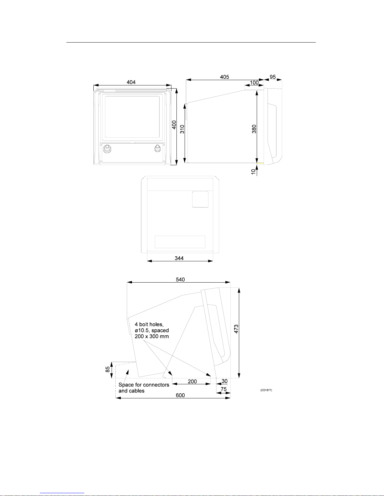
3.8 Weights and dimensions
Weight SD 570 Weight SE 570 Dimensions
Sonar Control
Unit
28 kg 28 kg Seefigure2
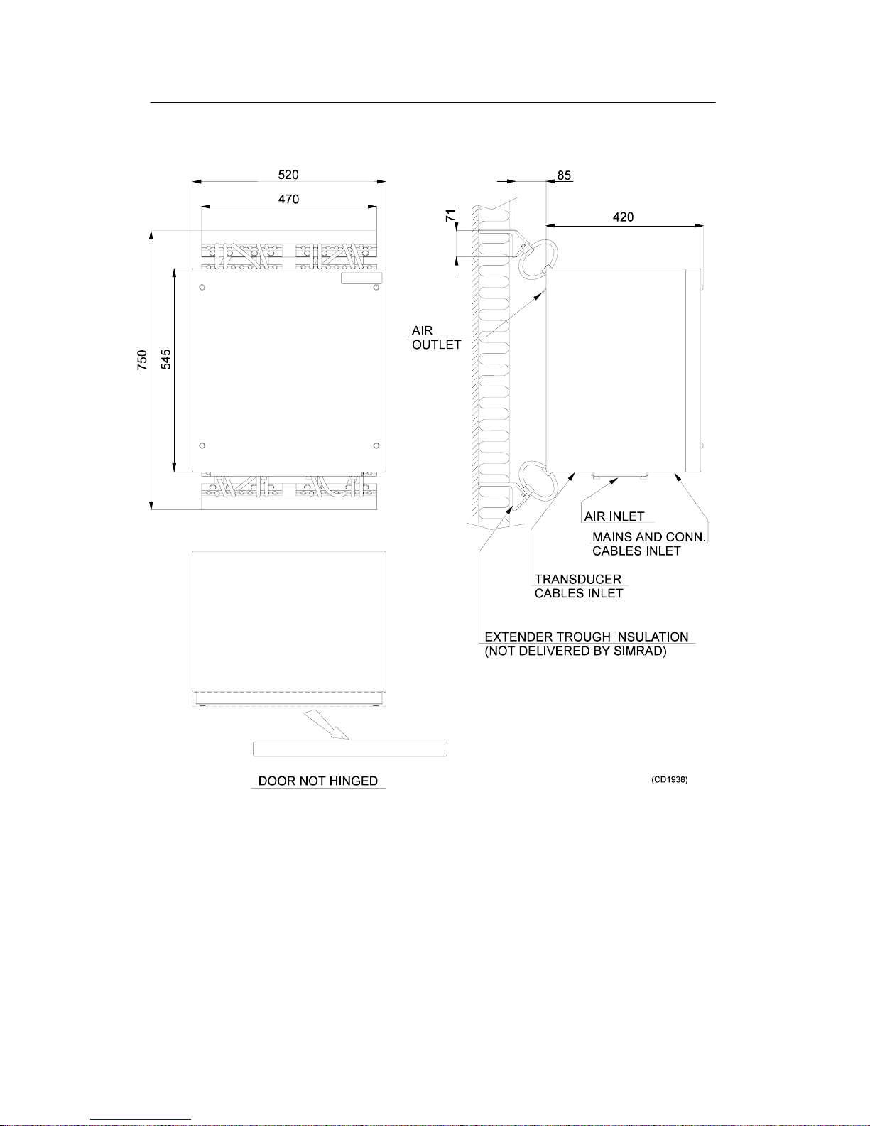
Transceiver Unit 75 kg 70 kg Seefigure3
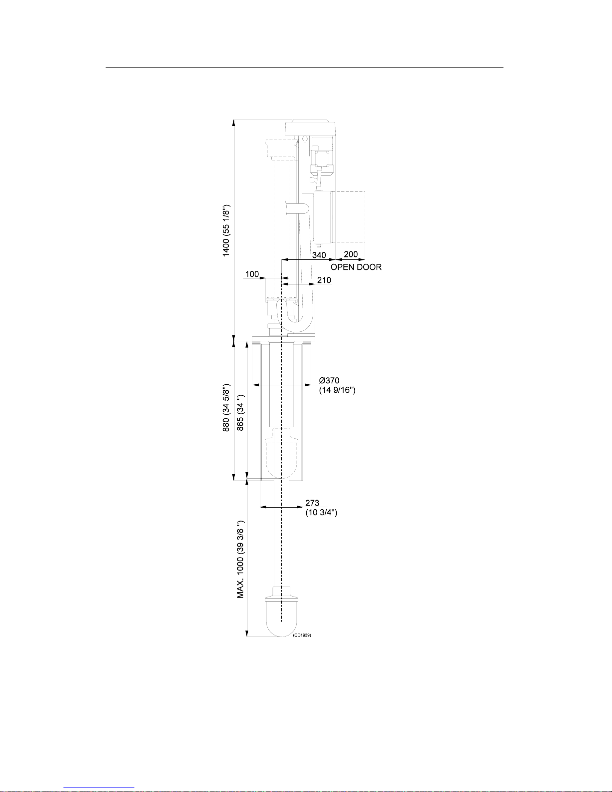
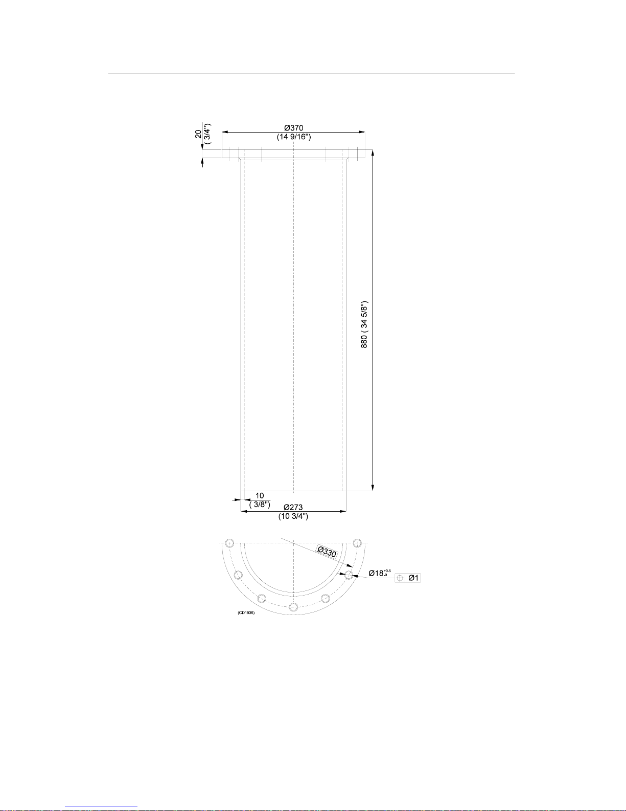
Hull Unit 275 kg 265 kg Seefigure4
Trunk (optional) 68 kg 68 kg Seefigure5
Table 2 Weights of the SD 570 and SE 570 sonars SP 270 sonar
The figures 2, 3, 4 and 5 show the outline dimensions of the
SD 570 / SE 570 units.
Page 25
Introduction
11
851--160115 / B
Figure 2 - Outline dimensions of the Sonar Control Unit
Page 26
Simrad SD570 / Base version
12
851--160115 / B
Figure 3 - Outline dimensions of the Transceiver Unit
Page 27
Introduction
13
851--160115 / B
Figure 4 - Outline dimensions of the Hull Unit
Page 28
Simrad SD570 / Base version
14
851--160115 / B
Figure 5 - Outline dimensions of the optional trunk
Page 29

Introduction
I
851--160116 / B
851- 160116 / AA000 / 3 - 11
Installation procedures
This section provides the necessary information for the
installation and cabling of the complete SD 570/ SE 570
sonar systems according to Simrad’s requirements.
Page 30

Simrad SD570 / Base version
II
851--160116 / B
Document revisions
Rev Date Written by Checked by Approved by
A Unknown
B 03.01.01 RBr ESB RBr
C
D
(The original signatures are recorded in the company’s logistic database)
Page 31

Introduction
III
851--160116 / B
Table of contents
1 INSTALLATION PLANNING 1. . . . . . . . . . . . . . . . . . . . . . . . . . . . . . . . . . .
1.1 General 1. . . . . . . . . . . . . . . . . . . . . . . . . . . . . . . . . . . . . . . . . . . . . . . . . . . . .
1.2 Location of the Hull Unit 1. . . . . . . . . . . . . . . . . . . . . . . . . . . . . . . . . . . . . .
1.3 Sonar room requirements 2. . . . . . . . . . . . . . . . . . . . . . . . . . . . . . . . . . . . .
2 INSTALLATION OF THE SONAR TRUNK 5. . . . . . . . . . . . . . . . . . . . . . .
2.1 Mounting of the trunk 5. . . . . . . . . . . . . . . . . . . . . . . . . . . . . . . . . . . . . . . .
2.2 Protecting blister 6. . . . . . . . . . . . . . . . . . . . . . . . . . . . . . . . . . . . . . . . . . . . .
2.3 Corrosion protection 6. . . . . . . . . . . . . . . . . . . . . . . . . . . . . . . . . . . . . . . . .
2.4 Trunk installation measurements 6. . . . . . . . . . . . . . . . . . . . . . . . . . . . . . .
3 INSTALLATION OF THE HULL UNIT 9. . . . . . . . . . . . . . . . . . . . . . . . . . .
3.1 Unpacking the Hull Unit 9. . . . . . . . . . . . . . . . . . . . . . . . . . . . . . . . . . . . . .
3.2 Mounting the Hull Unit 10. . . . . . . . . . . . . . . . . . . . . . . . . . . . . . . . . . . . . . .
3.3 Staying 11. . . . . . . . . . . . . . . . . . . . . . . . . . . . . . . . . . . . . . . . . . . . . . . . . . . . .
3.4 Alignment of the transducer 11. . . . . . . . . . . . . . . . . . . . . . . . . . . . . . . . . . .
3.5 Installation checklist 12. . . . . . . . . . . . . . . . . . . . . . . . . . . . . . . . . . . . . . . . . .
4 INSTALLATION OF THE TRANSCEIVER UNIT 13. . . . . . . . . . . . . . . . . .
5 INSTALLATION OF THE SONAR CONTROL UNIT 16. . . . . . . . . . . . . .
5.1 Location of the Sonar Control Unit 16. . . . . . . . . . . . . . . . . . . . . . . . . . . . .
5.2 Mounting of the Sonar Control Unit 17. . . . . . . . . . . . . . . . . . . . . . . . . . . .
Desk top mounting 17. .. . . . .. . . .. . . . .. . . .. . . . .. . . .. . . . .. . .
Panel mounting 18. . .. . . .. . . . .. . . .. . . . .. . . .. . . . .. . . .. . . . ..
Bulkhead mounting 18. .. . . .. . . . .. . . .. . . . . . . . .. . . . . . . . .. . .
6 CABLING 20. . . . . . . . . . . . . . . . . . . . . . . . . . . . . . . . . . . . . . . . . . . . . . . . . . .
6.1 Cable plan 20. . . . . . . . . . . . . . . . . . . . . . . . . . . . . . . . . . . . . . . . . . . . . . . . . .
6.2 The Sonar Control Unit cabling 22. . . . . . . . . . . . . . . . . . . . . . . . . . . . . . . .
6.3 The Transceiver Unit cabling 24. . . . . . . . . . . . . . . . . . . . . . . . . . . . . . . . . .
6.4 The Hull Unit cabling 27. . . . . . . . . . . . . . . . . . . . . . . . . . . . . . . . . . . . . . . .
7 CONNECTING AUXILIARY EQUIPMENT 28. . . . . . . . . . . . . . . . . . . . . . .
7.1 General 28. . . . . . . . . . . . . . . . . . . . . . . . . . . . . . . . . . . . . . . . . . . . . . . . . . . . .
7.2 Connecting the course gyro 29. . . . . . . . . . . . . . . . . . . . . . . . . . . . . . . . . . .
Connecting a course gyro with synchro output 29. .. . . .. . . . ..
Connecting a course gyro with stepper output 33. .. . . .. . . . .. .
Connecting a course gyro with serial line output 36. .. . . .. . . .
7.3 Connecting the speed log 39. . . . . . . . . . . . . . . . . . . . . . . . . . . . . . . . . . . . .
Connecting the pulse log 39. . . . . . .. . . . . . . . .. . . .. . . . .. . . .. . .
Page 32

Simrad SD570 / Base version
IV
851--160116 / B
Connecting a speed log with serial line output 40. . . .. . . . .. . .
7.4 Connecting other auxiliary equipment 42. . . . . . . . . . . . . . . . . . . . . . . . . .
7.5 Remounting the electronic drawer unit 42. . . . . . . . . . . . . . . . . . . . . . . . .
Page 33

Introduction
V
851--160116 / B
Document history
(The information on this page is for internal use)
Rev.A Original issue for Base version.
Rev.B Document transferred to Interleaf. No changes made to the text or
illustrations.
Page 34

Simrad SD570 / Base version
VI
851--160116 / B
Blank page
Page 35

Introduction
1
851--160116 / B
1 INSTALLATION PLANNING
Note ! For installation in an already installed trunk system, first read through
chapter 1.3 about the sonar room requirements. Then, for an already
installed SLor SX trunk system, continue to procedure 3 Installation
of the Hull Unit .
For installationin an already installed SK, SB or SQ trunk system,
refer to section Trunk systems in this manual.
1.1 General
This chapter provides the necessary information for the ship
designer to plan and carry out the installation of the SD 570/SE
570 hull system according to Simrad’s requirements. Study this
chapter thoroughly to achieve the recommended knowledge of
the procedures.
Note that individual installation drawings must be designed by
the shipyard, and the construction must be approved by the
classification authorities at the customer’s expense.
Simrad offers free advice for installation planning. The proposal
for the arrangement may be sent to Simrad for comments, or may
be worked out by Simrad. If such assistance is required, the
following drawings should be submitted:
· General arrangement
· Body plan and drawings of bottom tanks and cofferdam
· Sheer drawing
1.2 Location of the Hull Unit
The Hull Unit should preferably be located within 1/10 to 1/3 of
the ship’s length between perpendiculars (LBP), measured from
the fore perpendicular (FP). Refer to figure 1. Larger deviations
from this rule should not be made without consulting Simrad.
The Hull Unit may be located symmetrically on the centre line of
the vessel, or alongside the keel. When determining the exact
location, make sure that the transducer will have free view under
the keel (refer to figure 1).
The Hull Unit trunk must be installed such that it will be vertical
under normal operating conditions.
Water inlets and protruding details which create turbulence,
should not be located in front of the transducer. For the same
reason, check that the shell plating in front of the trunk is not
damaged.
Page 36

Simrad SD570 / Base version
2
851--160116 / B
Figure 1 - Location of the Hull Unit
1.3 Sonar room requirements
The sonar room should be dimensioned to house the Hull Unit
and the Transceiver Unit.This becausethe lengthof the flexi-hose
protected cabling from the Hull Unit to the Transceiver Unit is
limited to approximately 3.5 meters.
By installing the units in a well designed sonar room, the risk of
corrosion is reduced, the maintenance is simplified, and the
reliability is increased.
A suggested arrangement of the sonar room is shownin figure 2.
The free space should not be obstructed by girders or pipes etc.,
which might cause problems forthe installationand maintenance
work.
Access hatches
The sonar room must be accessible under all conditions, and the
doors or hatches should be so designed that the installed units can
be removed without being disassembled. A tackle carrier
designed for a load of a minimum of 2 tons should be mounted
above the Hull Unit. The tackle may be used to facilitate the
mounting of the trunk and Hull Unit, and is alsointended for use
in future service of the Hull Unit.
Heating
The sonar room should be furnished with a heating element of
1000 W, mounted close to the floor.
Insulation
The bulkhead must be insulated and plateddown to thefloor.The
insulation should equal a minimum of 50 mm of rock- wool.
Page 37

Introduction
3
851--160116 / B
Ventilation
The sonar room should preferably be connected to the ship’s
ventilation system. If this is not possible, two 3-inch vent pipes
must be laid from the sonar room to free air on deck. The air inlet
should be close to the floor, while the outlet should be placed as
high aspossible. Funnelsshould bemounted belowthe vent pipes
to collect condensed water.
To ensure the best possible ventilation, the outlet pipe should run
at least 4meters higher than the inletpipe. To keep rain and water
splash out, the pipes should be fitted with goosenecks or cowls.
Cable pipes
If the cable between the wheelhouse and the sonar room passes
through hatches or places where it can be damaged, it should be
run through pipes (2” pipes are recommended).
Bilge pump
The sonar room should be connected to the ship’s main bilge
pump system.If this is not possible, a separatebilge pump for the
sonar room must be installed.
Lighting
To simplify the installation and future maintenance, the sonar
room should be equipped with suitable lighting.
Docking
Make sure that there is ample space below the keel for mounting
the hull system, when docking the vessel.
To facilitate future docking, mark the position of the trunk as
indicated in figure 1
Flooring
When the installation is completed, the sonar room should be
suitably floored.
Page 38

Figure 2 - Example of sonar room arrangement,
seen from the bow
Simrad SD570 / Base version
4
851--160116 / B
Page 39

Introduction
5
851--160116 / B
2 INSTALLATION OF THE SONAR TRUNK
2.1 Mounting of the trunk
The location of the sonar trunk has to be carefully selected, as
described in chapter 1.2. Refer also to figures 4 and 5.
Note the orientation of the centre line of the trunk with regard to
the mounting bolts, shown in figure 3.
Note ! Remove the gasket on the top flange during the welding.
Figure 3 - Orientation of the sonar
trunk
The height from the topof the trunk flange to the underside of the
protection blister must be minimum 920 mm (361/4”) as shown
in figures 4 and 5.
The top flange must be parallel tothe construction loadline in the
fore- and- aft as well as the athwartships direction.
The installation trunk must be welded to an inserted plate which
should be 1.5 timesas thick asthe originalshell plate.The sizemay
be determined by the shipyard or the responsible maritime
authorities. The trunk must be stiffened to the inserted plate by
welding knee-plates on the trunk in both fore-and- aft and
athwartships directions.
Page 40

Simrad SD570 / Base version
6
851--160116 / B
2.2 Protecting blister
As illustrated in figures 4 and 5, a steel blister must be fitted for
protection. The blister shown in figure 4 is welded to the shell
plating and then filled with oil to prevent corrosion. This method
provides excellent protection and simplifies maintenance. The
blister shown in figure 5 is of the open type, to be welded to the
shell plating.
2.3 Corrosion protection
As soon as the trunk is mounted, and welding and grinding are
finished, the trunk should be painted with a quality protective
paint.
2.4 Trunk installation measurements
For future use, the measurements of the distance A, and the
heights B and Cshown in figures4 and5 haveto becarried outand
put into the table on the next page.
mm inches
Distance A
Height B
Height C
In case of an other installation solution, make a scheme with
dimensions below.
Page 41

Introduction
7
851--160116 / B
Figure 4 - Installation of trunk with extension
and oil- filled blister
Page 42

Simrad SD570 / Base version
8
851--160116 / B
Figure 5 - Installation of the trunk with open
protection blister. No trunk extension.
Page 43

Introduction
9
851--160116 / B
3 INSTALLATION OF THE HULL UNIT
3.1 Unpacking the Hull Unit
In order to prevent damage of the transducer and the transducer
cables while handling the Hull Unit, these parts are especially
protected. This means thatboth the transducer protection and the
cable protection should still be mounted to the Hull Unit when it
is being lowered down into the sonar room (see figure 6).
Figure 6 - Lifting the Hull Unit
Page 44

Simrad SD570 / Base version
10
851--160116 / B
j WhenunpackingtheHullUnit, first removethetopcover
fromthe woodenbox,then pulloutthe nailsmarkedwith
Indianink. Fasten thelifting deviceto the twolifting eye
bolts onthe top of the gallows andlift the Hull Unit with
the protections carefully out from the transport box.
3.2 Mounting the Hull Unit
The Hull Unit should normally be oriented with the
hoisting/lowering motor pointing aft (see figure 7). If this
orientation makes the motor control unit onthe HullUnit difficult
to access, the Hull Unit may be oriented in the most suitable
position.
Note ! The motor control unit should never be dismounted from the Hull Unit
(see text above).
j Use a tackle to lower the Hull Unit with the protections
downintothe sonarroom(seefigure 6).Removethe blind
cover from the trunk, and check that the gasket is not
damaged. Store the blind cover in the sonar room for
possible future use.
Figure 7 - Recommended orientation of the Hull Unit
j Removethetransportprotectionfromthetransducerand
lower the Hull Unit carefully down into the trunk.
Tightenthe flange nuts witha torque ofapproximately 6
kpm.
Page 45

Introduction
11
851--160116 / B
j Remove the cable protection box. The transducer cables
andconnectorshave tobekeptdry andhandledwithcare
to avoid mechanical damage.
3.3 Staying
The Hull Unit is constructed to be in the lower position with a
maximum speed of 15 knots.Toprevent unwanted vibrations, the
Hull Unit has to be stayed off against the bulkhead. Remove the
lifting rings onthe top of the gallows on the Hull Unitand use the
holes for fastening of the staying in the fore- and- aft direction. In
case of serviceon the Hull Unit,it should be possibleto removethe
staying.
3.4 Alignment of the transducer
Note that the transducer should not be mechanically aligned even
if the Hull Unit is oriented differently from figure 7.
The transducer alignment will be carried out later by turning the
echo picture in the computer.
Page 46

Simrad SD570 / Base version
12
851--160116 / B
3.5 Installation checklist
For the following check list, refer to the sonar room requirements
in chapter 1.3.
INSTALLATION CHECKLIST YES NO
Are the access hatches satisfactory?
Is the heating satisfactory?
Is the insulation satisfactory?
Is the ventilation satisfactory?
Are the access hatches satisfactory?
Is a bilge pump installed?
Is the lighting satisfactory?
Is the sonar room suitably floored?
If the answer to any of the questions is NO, make a note in the
installation certificate at the end of section Start-up procedures.
Page 47

Introduction
13
851--160116 / B
4 INSTALLATION OF THE TRANSCEIVER UNIT
Note ! The Transceiver Unit must be mounted as a complete unit, i.e. the door
should not be opened until the unit is securely fastened to the bulkhead.
Before starting the mounting of the Transceiver Unit, note that the
distance between the HullUnit and the Transceiver Unitis limited
because of the flexible transducer cables. Also remember to take
into consideration the necessary slack for lowering of the
transducer.
Do not fasten the transducer cables into the Transceiver Unit
before mentioned later in the start- up procedure.
The Transceiver Unit cabinet requires a minimum free bulkhead
space, which is shown in figure 8.
j Dismountthe twomounting bracketswhich arefastened
to theshock absorbers on theTransceiverUnit. An Allen
key is located in the plastic bag which is fastened to the
upper shock absorber.
j Weld the mounting brackets safely to the bulkhead as
shown in figure 8.
j Use a tackle carrier to lift the Transceiver Unit in
position, and bolt it to the mounting brackets with the
boltsincluded inthe delivery. These8 boltsare locatedin
the plastic bag that was fastened to the upper shock
absorber. Remember to fasten the grounding cable from
the Transceiver Unit to the mounting bracket as shown
in figure 9.
Page 48

Simrad SD570 / Base version
14
851--160116 / B
Figure 8 - Mounting the brackets for the
Transceiver Unit
Page 49

Introduction
15
851--160116 / B
Figure 9 - Mounting the Transceiver Unit
Page 50

Simrad SD570 / Base version
16
851--160116 / B
5 INSTALLATION OF THE SONAR CONTROL
UNIT
5.1 Location of the Sonar Control Unit
The Sonar Control Unit may bemounted on a desk top, ina panel,
or to the bulkhead. The necessary hardware for desk top and
panel mounting of the unit is included inthe delivery.It shouldbe
noted that the unit weighs approximately 28 kg, and this weight
must be considered when deciding how to mount it.
In order to secure the best location according to the routines on
board, the location of the Sonar Control Unit should be
thoroughly discussed with the skipper. Make sure that proper
operating and viewing height is provided.
Remember to include the ”Compass Safe Distance” when
planning the location:
· Sonar Control Unit with internal display
Standard compass: 1.4 m
Steering compass: 0.9 m
· Control Unit without display:
Standard compass: 1.1 m
Steering compass: 0.6 m
When mounting the unit, ensure that it is located to allow easy
access to the cable connection panel at the rear of the unit.
Ensure that the installation area is dry, and free from excessive
dust and vibration.
Page 51

Introduction
17
851--160116 / B
5.2 Mounting of the Sonar Control Unit
Desk top mounting
Refer to figure 10 for minimum space for the desk top mounting
of the cabinet.
j Dismount the mounting bracket from the Sonar Control
Unit by unscrewing the four bolts on the front. An Allen
key is located in the spare parts box.
j Bolt the mounting bracket securely to the desk top with
the four 10x30mm bolts which are located in the spare
parts box.
j Mountthe cabineton themounting bracketwith thefour
bolts.
Figure 10 - Desk top mounting
Page 52

Simrad SD570 / Base version
18
851--160116 / B
Panel mounting
j Dismount the mounting bracket from the Sonar Control
Unit by unscrewing the four bolts on the front. An Allen
key is located in the spare parts box.
j Cut the panel opening to the following size:
Width: 345 mm
Height: 380 mm
j Place the cabinet into the opening to mark the four
fastening holes.
j Remove the cabinet and drill the four fastening holes in
the panel.
Metal panel: Drill 5mm holes for threading with M6 tap, or
7mm holes if through- bolts with nuts are preferred.
Wooden panel: Drill 9mm holes for the four thread inserts
which are located in the spare parts box. Refer to figure 11 for
information about mounting the thread inserts.
Figure 11 - Mounting the thread inserts
j Place the cabinet into the opening and fasten it with the
four bolts.
Bulkhead mounting
To obtain the best operation position of the cabinet, the cabinet
should be mounted with a tilt angle of approximately 20 . An
optional mounting bracket can be delivered from Simrad.
j Dismount the mounting bracket from the Sonar Control
Unit by unscrewing the four bolts on the front. An Allen
key is located in the spare parts box.
Page 53

Introduction
19
851--160116 / B
j Bolt the bulkhead mounting bracket securely to the
bulkhead.
j Mountthe cabineton themounting bracketwith thefour
bolts.
Page 54

Simrad SD570 / Base version
20
851--160116 / B
6 CABLING
6.1 Cable plan
Figure 12 shows the cable plan for the SD 570 and SE 570 sonars.
The cable numbers also refer to the interconnection diagram,
drawing no. 824- 112979. This drawing is located in section
Drawings in thismanual. The cable specifications arelisted in the
table below.
Note that cable no. 4 is delivered with a standard length of 50
meters, and has a preconnected plug in the Sonar Control Unit
(wheelhouse) end. Thiscable is includedin the Sonar ControlUnit
package. As an option, cable no. 4 can be delivered in lengths of
75 or 100 meters.
Note that the length of the flexible transducer cables 7 and 8 is
fixed to approximately 3.5 meters.
Cable no. Cable type Cable dia (mm)
1 Screened cable, 2x0.5 mm
2
6
2 RCOP 5x1 mm
2
12
3,5 Mains cable, length 2 m 7
4,6 Data cable 8x(2+1)x0.5 mm
2
14
7,8 Flexi--cable, 3.5 m fixed length. Mounted
to Hull Unit
62
9
RCCP/750V 4x2.5 mm@
17
Page 55

Introduction
21
851--160116 / B
Figure 12 - Cable plan for the SD 570 / SE 570 sonars
Page 56

Simrad SD570 / Base version
22
851--160116 / B
6.2 The Sonar Control Unit cabling
All the cables to the Sonar Control Unit are to be plug connected
to the electronic drawer unit at the rear of the cabinet (see figure
13). The numbers on the figure refer to the cable numbers on the
cable plan.
Note ! In order to make service onthe Sonar Control Unit,the cables must have
a slack so the electronic drawer unit can have all the cables connected
while it is outside the cabinet. This couldbe either by pulling it out from
the front, or by reconnecting the cables with the drawer at floor level.
Note that cable no. 4 (refer to figure 12) is delivered with a
standard length of 50 meters, and has a preconnected plug in the
Sonar Control Unit (wheelhouse) end.
j Pull cable no. 4 from the wheelhouse to the sonar room.
Note that the preconnected plug should be connected to
the Sonar Control Unit in the wheelhouse. Remember to
include the slack for service purpose.
j The mains power cable (3) may be connected to a normal
mains outlet in the wheelhouse. If the delivered cable
does not fit, put on a suitable connector. Note that the
mainspower totheSonar ControlUnit can be115VAC or
230 VAC, and that this unit will automatically sense the
voltage.
The connection of the speed log (1) and the course gyro (2) will be
described in chapter 7.
Page 57

Introduction
23
851--160116 / B
Figure 13 - Cable connections to the Sonar Control Unit
Page 58

Simrad SD570 / Base version
24
851--160116 / B
6.3 The Transceiver Unit cabling
The cable numbers on figure 14 and in the following procedures
refer to the numbers on the cable plan and the interconnection
diagram.
Figure 14 - The cable connection in the bottom of the Transceiver
Unit
j All cable connections to the TransceiverUnit must have
aslack to allowthe TransceiverUnit to move up to10 cm
because of the flexible shock mounting.
j Start the termination with cable no. 6. This because this
cable is connected to the lowest row of the terminals on
E201. Use the surplus of cable no. 4, or a similar type of
cable. Use the cable gland on the left hand side (refer to
figure 14) and terminate the main screen of the cable as
shown in figure 15. For termination of each cable pair
with screen, refer to the interconnection diagram. Use a
part of the enclosed cable sleeve on the screen of each
cable pair.
Page 59

Introduction
25
851--160116 / B
Figure 15 - Termination of the cable main screen
j Continue with cable no. 4 throughthe cable gland on the
righthand side (seefigure 14) andmake the termination
of the main screen according to figure 15. Make the
connections to terminal E201 according to the
interconnection diagram.
Note that themains power connection to the Transceiver Unit can
be 115 VAC or 230 VAC. Use the following procedure for the
connection of the mains power:
j Pull out the mains input connector P201 on the power
supply in the Transceiver Unit. For location of the
connector, refer to figure 16.
j Set the mains voltage selector switch S201 on the Power
Supply and S203 on the HV Power Unit to correspond to
thecorrect mainsvoltage(115Vor230V), andreplace the
switch lock to secure the switch in the correct position.
j Set the service switch S202 on the Power Supply to OFF
(middle) position.
Page 60

Simrad SD570 / Base version
26
851--160116 / B
Figure 16 - The Power Supply and the HV Power Unit
j The mains power cable (3) may be connected to a normal
mains outlet in the sonar room. If the delivered cable
connector does not fit, put on a suitable connector.
j Do not mount the flexible transducer cables to the
T ransceiver Unit.
Page 61

Introduction
27
851--160116 / B
6.4 The Hull Unit cabling
Connection of cable no. 6 in the motor control unit:
j Usethe cableglandonthe right--handside,and makethe
termination of the main screen according to figure 15.
j Makea slackon thecableinside themotorcontrol unitas
shown on figure 17, and make the connections to the
terminalE301 accordingtothe interconnectiondiagram.
Connection of cable no. 9 in the motor control unit:
j Use the cable gland on the left--hand side, and make the
termination of the cable screen in the cable gland.
j Make the connections of the three--phase mains power
directly to the motor overload switch S303 according to
theinterconnection diagram. Thegrounding wireshould
be connected to the ground terminal beside the overload
switch.
Figure 17 - Connections to the Hull Unit
Page 62

Simrad SD570 / Base version
28
851--160116 / B
7 CONNECTING AUXILIARY EQUIPMENT
7.1 General
It is not necessary to make the connection of the auxiliary
equipment before the start-up procedure is finished, and this
equipment may therefore be connected later. Anyhow, do not
connect the plugs for the auxiliary equipment to the Sonar
Control Unit before mentioned in a later chapter.
The SD 570 / SE 570 sonars require connection of a speed log and
a course gyro. An inaccurate log or gyro input will cause
inaccurate indication of the vessel and target movements.
Speed log:
· Pulse log: 100, 200 or 400 pulses/nm.
· Serial line, standard NMEA 0183; RS232, RS422 or Current
loop.
Course gyro:
· 3- phase synchro signal, 20- 220V L- L, 50/60/400Hz.
· Gear ratio 1:360, 1:180, 1:90, 1:36.
· 3- phase stepper signal, 20-220V L- L.
Gear ratio 1:360, 1:180, 1:90, 1:36.
· Serial line, standard NMEA 0183; RS232, RS422 or Current
loop.
Echo sounder:
In order to get a depth indication on the catch control page on the
sonar, one of the following Simrad echo sounders can be
connected:
· EQ50, EQ55, EQ100, ES60, ES380 series, ES500 (RS232 serial
line).
Trawl system:
In order to get the trawl information on the sonar display, one of
the following Simrad trawl systems can be connected:
· FS Trawl sonar (RS 232 serial line or 20mA current loop).
· ITI Integrated Trawl Instrumentation (RS232 serial line).
Page 63

Introduction
29
851--160116 / B
7.2 Connecting the course gyro
The Sonar Control Unit can be connected to a course gyro with
one of the following outputs (tick off for the type which will be
connected):
j 3--phase synchro signal See chapter 7.2.1
j 3--phase stepper signal See chapter 7.2.2
j Serial line (NMEA 0183) See chapter 7.2.3
Connecting a course gyro with synchro output
j First, get the specifications of the gyro to fill in the
following data:
SYNCHRO DATA SPECIFICATIONS LEGAL VALUES
OUTPUT VOLTAGE 20 to 220 VAC
FREQUENCY 50/60/400 Hz
GEAR RATIO 1:360/1:180/1:90/1:36
If it is difficult to find the specifications for the gyro, the output
voltage and frequency can be measured in the following way:
j The output voltage can be measured by an AC voltmeter
or by an oscilloscope on the reference output R1 & R2.
Notethat ifanoscilloscopeisused,thereferenceprobe on
the oscilloscope must not be connected to the mains
ground, and the measured peak to peak value of the
output voltage must be divided by 2 Ö2 to get the RMS
voltage.
j Fill the output voltage value into the table above.
j The frequencycan be measured by an oscilloscope onthe
reference output R1 & R2. Note that the referenceprobe
on the oscilloscope must not be connected to the mains
ground.Calculate thefrequency1/T(T isthe timefor one
sine wave) and fill the result into the table above.
j If the gear ratio of the gyro output also is unknown, this
has to be tried out later when testing the readout of the
gyroon theSonarControlUnit. Insuch case,set thegear
ratio to 1:360.
When connecting the gyro cable to the 15 pin D-connector, note
that each of the three phases S1, S2, S3 and the reference R1 has
three different connection pins, marked L (Low), M (Medium)
and H (High). These pins are used for different gyro output
voltage values as indicated for the connections below:
Page 64

Simrad SD570 / Base version
30
851--160116 / B
Signal phase 1: S1-L (20- 70V) pin 2
S1- M (80- 140V) pin 9
S1- H (150- 220V) pin 1
Signal phase 2: S2-L (20- 70V) pin 11
S2- M (80- 140V) pin 3
S2- H (150- 220V) pin 10
Signal phase 3: S3-L (20- 70V) pin 5
S3- M (80- 140V) pin 12
S3- H (150- 220V) pin 4
Reference 1: R1- L (20- 70V) pin 14
R1- M (80- 140V) pin 6
R1- H (150-220V) pin 13
Reference 2: R2 pin 8
j Locate the 15 pin D--connector, the connector housing
and the shrink tube in the spare parts box. Refer to the
output voltage in the table for the synchro data, and
make the connections to the 15 pin D--connector with
reference to the pin--connection list above. Also refer to
figure 18, which shows the pin location of the connector
seenfromthewiresolderingside.Thecable screenshould
be connected to the connector housing.
Figure 18 - Connections for a gyro with
synchro output
In order to read the data from the gyro, some DIL switches on the
printed circuit board in the electronic drawer unit behind the
operator panel must be selected. Use the following procedure to
set the switches:
Page 65

Introduction
31
851--160116 / B
j Set the switch S101 at the rear panel on the Sonar
Control Unit to OFF position. For location of the switch,
refer to figure 13.
j Disconnect allconnections tothe rear panelon the Sonar
Control Unit.
j Usethe 3mmAllenkeywhichislocatedin the spareparts
boxto unscrewthe fourscrewsonthefrontoftheoperator
panel, and pull the electronic drawer carefully out. Note
thetwocablesto thedisplayonthetopof thedrawerunit.
j Disconnect the two display cable plugs on the drawer
unit, and dismount the top cover of the drawer.
j Locate the DIL switch S2 (referto figure 19), and setthe
switches according to table.
DIL SWITCH S2
GYR
O
1 2 3 4 5 6 7 8
50/60 Hz OFF OFF OFF OFF OFF OFF OFF ON
1:360
400 Hz OFF OFF OFF OFF OFF OFF OFF OFF
50/60 Hz OFF OFF OFF ON OFF OFF OFF ON
SYN-
1:180
400 Hz OFF OFF OFF ON OFF OFF OFF OFF
CHR
O
50/60 Hz OFF OFF OFF OFF ON OFF OFF ON
1:9
0
400 Hz OFF OFF OFF OFF ON OFF OFF OFF
50/60 Hz OFF OFF OFF ON ON OFF OFF ON
1:3
6
400 Hz OFF OFF OFF ON ON OFF OFF OFF
Do not insert the electronic drawer unit until mentioned in a later
chapter.
Page 66

Simrad SD570 / Base version
32
851--160116 / B
Figure 19 - The electronic drawer unit
Page 67

Introduction
33
851--160116 / B
Connecting a course gyro with stepper output
j First, get the specification of the gyro to fill in the
following data:
STEPPER DATA SPECIFICATIONS LEGAL VALUES
OUTPUT VOLTAGE 20 to 220 VAC
REF. POLARITY + REF. or -- REF
GEAR RATIO 1:360/1:180/1:90/1:36
If it is difficult to find the specifications for the gyro, the output
voltage and the referencepolarity canbe measuredby avoltmeter
in the following way:
j Connect the positive probe from the voltmeter to the
stepper reference output, and the negative probe to one
of the three signal phases which have a signal output.
Note that one or two signalphases always should have a
signal output voltage.
j Fill the highest measured output voltage value into the
table above.
j When readingthe signal outputvoltage, note thevoltage
polarity. If it is positive,the reference polarity is positive
(+ REF), and if it is negative, the reference polarity is
negative (-- REF). Fill the result into the table above.
j If the gyro output is specified to 6 step/degree, this is
equal to a gear ratioof 1:360. If the gear ratioof the gyro
output is unknown, this has to be tried out later when
testing the readout from the gyro on the Sonar Control
Unit. In such case, set the gear ratio to 1:360.
j Note that for somesteppertypegyros,the outputvoltage
is only half--wave rectified. This has to be checked by an
oscilloscope and ticked off below
j Full--wave rectified.
j Half--wave rectified.
Page 68

Simrad SD570 / Base version
34
851--160116 / B
When connecting the gyro cable to the 15 pin D-connector, note
that each of the three phases S1, S2, S3 has three different
connection pins, marked L (Low), M (Medium) and H (High).
These pins are used for different gyro output voltage values as
indicated for the connections below:
Signal phase 1: S1-L (20- 70V) pin 2
S1- M (80- 140V) pin 9
S1- H (150- 220V) pin 1
Signal phase 2: S2-L (20- 70V) pin 11
S2- M (80- 140V) pin 3
S2- H (150- 220V) pin 10
Signal phase 3: S3-L (20- 70V) pin 5
S3- M (80- 140V) pin 12
S3- H (150- 220V) pin 4
Reference : +/- REF pin 7
-/+ REF(see note) pin 15
Note ! If the output voltage is only half-wave rectified, the other reference from
the gyro which is not used for the three phases must be connected to pin
15.
j Locate the 15 pin D--connector, the connector housing
and the shrink tube in the spare parts box. Refer to the
output voltage which was written into the table for the
stepperdata specifications,and make the connections to
the 15--pin D--connector with reference to the
pin--connection list above. Also refer to figure 20 which
showsthepinlocationofthe connectorseenfromthewire
soldering side. The cable screen should be connected to
the connector housing.
Figure 20 - Connections for a gyro with stepper output
Page 69

Introduction
35
851--160116 / B
In order to read the data from the gyro, some DIL switches on the
printed circuit board in the electronic drawer unit behind the
operator panel must be selected. Use the following procedure to
set the switches:
j Set the switch S101 at the rear panel on the Sonar
Control Unit to OFF position. For location of the switch,
refer to figure 13.
j Disconnect allconnections tothe rear panelon the Sonar
Control Unit.
j Use the3mm Allenkey to unscrewthe fourscrewson the
frontoftheoperator panel,andpullthe electronicdrawer
carefullyout.Notethetwo cablestothedisplayonthe top
of the drawer unit.
j Disconnect the two display cable plugs on the drawer
unit, and dismount the top cover of the drawer.
j Refer to figure 19, and set the links LK19, LK20 and
LK21 to position A.
j Locate the DIL switch S2 (referto figure 19), and setthe
switches according to the table below.
DIL SWITCH S2
GYR
O
1 2 3 4 5 6 7 8
+ REF ON OFF OFF OFF OFF OFF OFF OFF
1:360
-- REF ON ON OFF OFF OFF OFF OFF OFF
+ REF ON OFF OFF ON OFF OFF OFF OFF
STEP-
1:180
-- REF ON ON OFF ON OFF OFF OFF OFF
PER
+ REF ON OFF OFF OFF ON OFF OFF OFF
1:9
0
-- REF ON ON OFF OFF ON OFF OFF OFF
+ REF ON OFF OFF ON ON OFF OFF OFF
1:3
6
-- REF ON ON OFF ON ON OFF OFF OFF
Do not insert the Control Unit drawer until mentioned in a later
chapter.
Page 70

Simrad SD570 / Base version
36
851--160116 / B
Connecting a course gyro with serial line
output
The Sonar ControlUnit can read the course gyro data (and/or the
speed log data) from a serial line with on ofthe followingoutputs
(tick off for the type which will be connected):
j RS232 Serial line
j RS422 Serial line
j 20mA current loop
The format of the serial line data is standard NMEA 0183, and the
telegram can contain both the course and speed data (refer to the
telegram format in the end of this chapter).
When connecting the 9-pin D- connector, note that each of the
three types of serial lines has different connection pins:
RS232: Serial line signal PORT B pin-2
Signal reference PORT B pin- 5
RS422: RS422+ PORT B pin- 1
RS422$ PORT B pin- 4
20mA current loop: CLI+ PORT B pin- 6
CLI- PORT B pin-9
j Use a 9--pin D--connector, male type, for connecting the
serial line to port B on the Sonar Control Unit (this
connector is not included in the delivery). To make the
connections, refer to the pin connection list above, and
figure 21 which shows the pin location of the connector
seenfromthewiresolderingside.Thecable screenshould
be connected to the connector housing.
j In order to read the data from the gyro, some DIL
switches and links on the printed circuit board in the
electronicdrawerunitbehind theoperatorpanel mustbe
selected.Use the followingprocedureto set the switches:
j Set the switch S101 at the rear panel on the Sonar
Control Unit to OFF position. For location of the switch,
refer to figure 13.
j Disconnect allconnections tothe rear panelon the Sonar
Control Unit.
j Use the3mm Allenkey to unscrewthe fourscrewson the
frontoftheoperator panel,andpullthe electronicdrawer
carefullyout.Notethetwo cablestothedisplayonthe top
of the drawer unit.
Page 71

Introduction
37
851--160116 / B
Figure 21 - Connections for a gyro with
serial line output
j Disconnect the two display cable plugs on the drawer
unit, and dismount the top cover of the drawer.
j Locate the DIL switch S2 (referto figure 19), and setthe
switches according to the table on next page.
DIL SWITCH S2
GYR
O
1 2 3 4 5 6 7 8
SERIAL LINE OUTPUT OFF OFF OFF OFF OFF ON OFF OFF
Locate the links LK2, LK3 and LK6 on the Control Unit Board,
(see figure 19) and set the links according to the table below.
GYRO LINK SETTING
LK2 LK3 LK6
RS232 OUT IN OUT
RS422 OUT OUT IN
20 mA current loop IN OUT OUT
Do not insert the Control Unit drawer until mentioned in a later
chapter.
Page 72

Simrad SD570 / Base version
38
851--160116 / B
The serial line telegram format for the course and speed data:
$xxHDT,ggg.g,T<cr><1f> Heading, Degrees True
$xxHDM,ggg.g,M<cr><1f> Heading, Degrees Magnetic
$xxVGT,ggg.g,T,ggg.g,M,nn.n,N,kk.k,K<cr><1f> Actual track
and ground speed
$xxVHW,ggg.g,T,ggg.g,M,nn.n,N,kk.k,K<cr><1f> Heading
and water speed
xx is indicator for transmitter, for instance:
’HE’ = gyro, earth seeking
’GP’ = Precision Global Positioning System
Heading data:
ggg.g is heading in degrees.
The gyro value can have variable amounts of digits in front of
comma (max. 3), and after comma (min. 0). Comma can also be
omitted. Leading zeroes and spaces are accepted.
In the twolast telegrams, the ”True” valueis used ifboth true and
magnetic values are transmitted.
Speed data:
nn.n is speed in Nautical miles
kk.k is speed in Kilometer per hour
The speed value should have min. 1, max. 2 digits in front of
comma, and 1 after. Leading zeroes and spaces are accepted.
Page 73

Introduction
39
851--160116 / B
7.3 Connecting the speed log
The Sonar Control Unit can be connected to a speed log with one
of the following outputs (tick off for the type which will be
connected):
j Pulse log (100, 200 or 400 pulses per nautical mile)
j Serial line (RS232, RS422 or 20mA current loop)
The connection of these different speed log outputs is described
in the following chapters.
Connecting the pulse log
The Sonar Control Unit can be connected to a pulse log with one
of the following outputs (tick off for the type which will be
connected):
j 100 pulses per nautical mile
j 200 pulses per nautical mile
j 400 pulses per nautical mile
For anytype of log output (relay, open collector, or opto-coupler),
the output must be free from other connections.
Figure 22 shows the connection of a pulse log with relay output.
For connection of open collector, or opto- coupler outputs, be
aware of the polarization (see figure 23).
j Locatethe9--pinD --connector,theconnectorhousingand
the shrink tube in the spare parts box, and make the
plug--connections. The cable screen should be connected
to the connector housing.
Figure 22 - Connections for a pulse log with
relay output
j Locate the DIL switch S1 on the Control Unit Board
(refer to figure 19), and set the switches according to the
table below.
Page 74

Simrad SD570 / Base version
40
851--160116 / B
DIL SWITCH S1
SPEED
1 2 3 4 5 6 7 8
100 pulses per nautical
mile
OFF OFF ON OFF OFF OFF OFF OFF
200 pulses per nautical
mile
OFF OFF OFF ON OFF OFF OFF OFF
400 pulses per nautical
mile
OFF OFF ON ON OFF OFF OFF OFF
Do not insert the Control drawer unit before mentioned in a later
chapter.
Figure 23 shows the pulse log interface circuit on the ControlUnit
Board.
Figure 23 - Pulse log interface
When the system is started up, an oscilloscope can be connected
to the test point TP5 to check if the pulse log signal is coming
through the comparator U45 (TP4 is GND). If the signal is not
coming through the comparator, try to adjust the 10- turn
potmeter R45. In case of noise problems, R45 can be adjusted for
noise limitation .
Connecting a speed log with serial line output
The Sonar Control Unit can read the speed log data (and/or the
course gyro data) from a serial line with on of the following
outputs (tick off for the type which will be connected):
j RS232 serial line
j RS422 serial line
j 20mA current loop
The format of the serial line data is standard NMEA 0183, and the
telegram can contain both the course and speed data (refer to the
telegram format in the end of chapter 7.2.3).
Page 75

Introduction
41
851--160116 / B
When connecting the 9-pin D- connector, note that each of the
three types of serial lines has different connection pins:
RS232: Serial line signal PORT B pin-2
Signal reference PORT B pin- 5
RS422: RS422+ PORT B pin- 1
RS422- PORT B pin- 4
20mA current loop: CLI+ PORT B pin- 6
CLI- PORT B pin- 9
j Use a 9--pin D--connector, male type, for connecting the
serial line to port B on the Sonar Control Unit (this
connector is not included in the delivery). To make the
connections, refer to the pin connection list above, and
figure 24 which shows the pin location of the connector
seenfromthewiresolderingside.Thecable screenshould
be connected to the connector housing.
Figure 24 - Connections for a speed log with
serial line output
j Locate the DIL switch S1 on the Control Unit Board
(refer to figure 19), and set the switches according to the
table below.
DIL SWITCH S1
SPEED
1 2 3 4 5 6 7 8
SERIAL LINE OUTPUT OFF OFF OFF ON ON OFF OFF OFF
j Locate the links LK2, LK3 and LK6 on the Control Unit
Board, (see figure 19) and set the links according to the
table below.
Page 76

Simrad SD570 / Base version
42
851--160116 / B
SPEED LINK SETTING
LK2 LK3 LK6
RS232 OUT IN OUT
RS422 OUT OUT IN
20 mA current loop IN OUT OUT
Do not insert the Control drawer unit before mentioned in a later
chapter.
7.4 Connecting other auxiliary equipment
If any other optional equipment is to be connected (echo
sounderortrawlsystem),refertotheappendixesin thismanual.
7.5 Remounting the electronic drawer unit
When the DIL switches and link settings for all auxiliary
equipment are correct, use the following procedure to remount
the electronic drawer unit:
j Remount the top cover on the drawer unit.
j Reconnect the two display cables.
j Lock the two display cables in the cable locker, and
arrange the cables as shown in figure 25. Enter the
drawer unit carefully into the cabinet, and check the
cables while entering the drawer. Note that the two
guiding pins at the inside of the rear wall in the cabinet
should enter the two guiding holes at the rear of the
drawer unit.
j Fasten the electronic drawer unit with the four 3mm
Allen screws on the front of the operator panel.
Page 77

Introduction
43
851--160116 / B
Figure 25 - Mounting the electronic drawer
unit
Page 78

Simrad SD570 / Base version
44
851--160116 / B
Blank page
Page 79

Introduction
I
851--160117 / B
851- 160117 / AA000 / 3 - 11
Start- up procedures
This section contains the start- up procedures to be
carried out after installation of the SD570/SE570 sonar.
Page 80

Simrad SD570 / Base version
II
851--160117 / B
Document revisions
Rev Date Written by Checked by Approved by
A Unknown
B 03.01.01 RBR ESB RBR
C
D
(The original signatures are recorded in the company’s logistic database)
Page 81

Introduction
III
851--160117 / B
Table of contents
1 PREPARING THE START--UP 1. . . . . . . . . . . . . . . . . . . . . . . . . . . . . . . . .
1.1 Before start- up check list 1. . . . . . . . . . . . . . . . . . . . . . . . . . . . . . . . . . . . . .
1.2 Starting up the stand- by power supply 2. . . . . . . . . . . . . . . . . . . . . . . . .
2 THE HULL UNIT 4. . . . . . . . . . . . . . . . . . . . . . . . . . . . . . . . . . . . . . . . . . . . .
2.1 Starting up the Hull Unit 4. . . . . . . . . . . . . . . . . . . . . . . . . . . . . . . . . . . . .
2.2 Adjusting the middle position switch 10. . . . . . . . . . . . . . . . . . . . . . . . . . .
3 THE SONAR CONTROL UNIT 12. . . . . . . . . . . . . . . . . . . . . . . . . . . . . . . . .
3.1 Starting up the sonar control unit 12. . . . . . . . . . . . . . . . . . . . . . . . . . . . . .
3.2 Checking the control panel 14. . . . . . . . . . . . . . . . . . . . . . . . . . . . . . . . . . . .
4 CHECKING THE HOISTING/LOWERING SYSTEM 17. . . . . . . . . . . . . . .
4.1 Checking the bridge functions 17. . . . . . . . . . . . . . . . . . . . . . . . . . . . . . . . .
4.2 Checking the sonar room functions 19. . . . . . . . . . . . . . . . . . . . . . . . . . . . .
5 THE TRANSCEIVER UNIT 21. . . . . . . . . . . . . . . . . . . . . . . . . . . . . . . . . . . .
5.1 Starting up the Transceiver Unit 21. . . . . . . . . . . . . . . . . . . . . . . . . . . . . . .
5.2 Self- noise test 22. . . . . . . . . . . . . . . . . . . . . . . . . . . . . . . . . . . . . . . . . . . . . . .
5.3 Connecting the transducer 23. . . . . . . . . . . . . . . . . . . . . . . . . . . . . . . . . . . .
6 SYSTEM START--UP 26. . . . . . . . . . . . . . . . . . . . . . . . . . . . . . . . . . . . . . . . .
6.1 Air- bleeding of the sonar trunk 26. . . . . . . . . . . . . . . . . . . . . . . . . . . . . . . .
6.2 Preparing the system start- up 26. . . . . . . . . . . . . . . . . . . . . . . . . . . . . . . . .
6.3 Starting up the transmitter 27. . . . . . . . . . . . . . . . . . . . . . . . . . . . . . . . . . . .
Actions on the sonar control unit 27. .. . . .. . . . .. . . .. . . . . . . . .
Actions on the Transceiver Unit 29. . .. . . .. . . . .. . . .. . . . .. . . .
6.4 Alignment of the sonar picture 31. . . . . . . . . . . . . . . . . . . . . . . . . . . . . . . .
7 TESTING THE AUXILIARY EQUIPMENT 32. . . . . . . . . . . . . . . . . . . . . . .
7.1 General 32. . . . . . . . . . . . . . . . . . . . . . . . . . . . . . . . . . . . . . . . . . . . . . . . . . . . .
7.2 Checking the course gyro readout 32. . . . . . . . . . . . . . . . . . . . . . . . . . . . . .
7.3 Checking the speed log readout 34. . . . . . . . . . . . . . . . . . . . . . . . . . . . . . . .
7.4 Checking the echo sounder and trawl system readout 34. . . . . . . . . . . .
7.5 Remounting the electronic drawer unit 35. . . . . . . . . . . . . . . . . . . . . . . . .
8 FINAL TESTS AND MEASUREMENTS 37. . . . . . . . . . . . . . . . . . . . . . . . .
8.1 General 37. . . . . . . . . . . . . . . . . . . . . . . . . . . . . . . . . . . . . . . . . . . . . . . . . . . . .
8.2 Source level (SL) measurements 37. . . . . . . . . . . . . . . . . . . . . . . . . . . . . . . .
8.3 Receiving voltage response (VR) 42. . . . . . . . . . . . . . . . . . . . . . . . . . . . . . .
8.4 Noise/speed curve 44. . . . . . . . . . . . . . . . . . . . . . . . . . . . . . . . . . . . . . . . . . .
9 INSTALLATION REMARKS AND SIGNATURE 48. . . . . . . . . . . . . . . . . .
Page 82

Simrad SD570 / Base version
IV
851--160117 / B
Document history
(The information on this page is for internal use)
Rev.A Original issue for Base version.
Rev.B Document transferred to Interleaf. No changes made to text or illustra-
tions.
Page 83

Introduction
1
851--160117 / B
1 PREPARING THE START--UP
1.1 Before start--up check list
Before beginning with the start- up procedure, check the
following:
Sonar Control Unit:
j Check thatno connectionsare madetothe SonarControl
Unit.
Transceiver Unit:
j Checkthat theship’smainsfuses to theTransceiverUnit
are disconnected.
j Check thatthe mains inputconnector P201 on the power
supply in the Transceiver Unit is disconnected.
j Check thatthe transducer plugsare not connectedto the
front of the transceiver PCBs.
Hull Unit:
j Check that the ship’s mains fuses to the Hull Unit are
disconnected.
Page 84

Simrad SD570 / Base version
2
851--160117 / B
1.2 Starting up the stand--by power supply
In order to start up the sonar units, the 24 VDC stand-by power
supply in the Transceiver Unit has to be started up first. Refer to
figure 1 and use the following procedure to start up the stand-by
power supply:
j Check that the mains input connector P201 on the front
of the power supply in the Transceiver Unit is
disconnected.
j Check that the switch S202 on the front of the power
supply is set to OFF (middle) position.
j Insert the mains fuses to the Transceiver Unit on the
ship’s mains switchboard.
j Measure the mains voltage supplied to the Transceiver
Unit.
Write the measured voltage here:...................VAC.
j Check if the voltage selector switches S201 on the power
supply andS203 on the HV power unitcorrespond to the
measured voltage (115V or 230V position).
j Reinsert the mains input connector P201 on the front of
the power supply.
j Check that the lamps L201 and L202 on the front of the
power supply illuminate.
j Check thatthe small LED(Light Emitting Diode)for the
+24Vstand --by powerontheTransceiverInterfaceBoard
(TIB) illuminates (refer to indication on the front of the
power supply).
Now the 24 VDCstand-by poweris suppliedboth tothe HullUnit
and to the connector for the Sonar Control Unit.
Page 85

Introduction
3
851--160117 / B
Figure 1 - The transceiver power system
Page 86

Simrad SD570 / Base version
4
851--160117 / B
2 THE HULL UNIT
2.1 Starting up the Hull Unit
WARNING ! Before starting up the equipment on a launched ship,
make sure that there is sufficient depth for the
transducer to be lowered. If starting up the equipment
on board a docked ship, check both under the ship and
inside the sonar room that neither persons nor things
are in the way for the transducer or the lowering and
hoisting machinery.
j Use a spanner to open the door on the motor control unit
which is mounted on the Hull Unit.
j Release the motor overload switch S301 in the motor
control unit by pressing the red button marked ”0” (see
figure 2).
j Set the hoisting/lowering switch S302 in the motor
control unit to STOP position.
j Unscrew thetiming belt coveron the topof theHull Unit
(see figure 3). Locate the hand crank inside the motor
control unit. Fasten the hand crank to the hoisting
spindle and lower the transducer manually
approximately 20 cm (8”).
j Remove the hand crank from the spindle, but do not
replace it in the motor control unit!
j Remountthetimingbelt coveronthetopofthe HullUnit.
j Setthehoisting/loweringswitch S302toHOISTposition,
and check that the hoisting contactor K301 is activated
when pressing the hand crank safety switch S303.
j Set the hoisting/lowering switch S302 to LOWER
position, and check that the lowering contactor K302 is
activated when pressing the hand crank safety switch
S303.
j Set the hoisting/lowering switch S302 to STOP position.
j Replace the hand crank to its storage position in the
motor control unit.
j Activate the hoisting contactor K301 by setting the
hoisting/lowering switch S302 to HOIST position, and
check if the contactor is deactivated when pressing the
upper limit switch S304 upwards (see figure 3).
Page 87

Introduction
5
851--160117 / B
Figure 2 - The motor control unit
j Activate the lowering contactor K302 by setting the
hoisting/lowering switch S302 to LOWER position, and
check if the contactor is deactivated when pressing the
lower limit switch S305 downwards.
j Set the hoisting/lowering switch S302 to STOP position.
j Reinsert the three--phase mains fuses for the Hull Unit
on the ship’s mains switchboard.
j Measure thethree--phase voltageon the terminals of the
motor overload switch S301 in the motor control unit.
Page 88

Simrad SD570 / Base version
6
851--160117 / B
j Writemeasuredthree--phase voltagehere:.......................
j The hoist/lower motor is preconnected for 380V/440V
three--phase. If the measured three--phase voltage is
230V, the motor has to be reconnected.Remove the cover
forthe mainsconnection on the motor,andrefer tofigure
4 to link the motor connections to correspond to the
measured voltage.
j Adjust the release current of the motor overload switch
S301 according to the three-- phase voltage:
230V: 2.4 A
380/440V: 1.6 A
j Remove the hand crank from its storage position.
j Set the motor overload switch to normal position by
pressing the black button marked ”1”.
j Set the hoisting/lowering switch S302 to LOWER.
j Check the training direction of the hoisting/lowering
motor by briefly pressing the hand crank safety switch
S303.
j If thetransducer shaft washoisted, disconnectthe ship’s
three--phase mains fuses and change two of the
connectionstotheterminalsonthemotoroverloadswitch
S301. Reinsert the three--phase mains fuses.
j Set the hoisting/lowering switch S302 to STOP.
j Put thethe hand crankback to its storage position in the
motor control unit.
j Check ifthere is sufficientspace to lowerthe transducer.
j Make surethat theflexible transducer cablesare insuch
a position that the transducer can be lowered without
stretching or hard--bending the cables. Watch this
carefully during the next steps in this procedure.
j Set the hoisting/loweringswitch S302 to LOWERfor full
lowering of the transducer. The lowering will
automatically stop when the top of the transducer shaft
hits the lower limit switch S305.
j Make a preliminary fastening of the flexible transducer
cables and watch the cables during the hoisting in the
next step.
Page 89

Introduction
7
851--160117 / B
Figure 3 - The Hull Unit
Page 90

Simrad SD570 / Base version
8
851--160117 / B
j Set the hoisting/lowering switch to HOIST for full
hoisting of the transducer. The hoisting will stop
automatically when the top of the transducer hits the
upper limit switch S304.
j Repeat the hoisting/lowering to find the best position for
a permanent fastening of the flexible cables.
j Set the hoisting/lowering switch to STOP.
Page 91

Introduction
9
851--160117 / B
Figure 4 - Mains connection to the motor
Page 92

Simrad SD570 / Base version
10
851--160117 / B
2.2 Adjusting the middle position switch
Normally, when the transducer is selected to middle position on
the Sonar Control Unit, only one half of the transducerface should
be outside the sonar trunk (see figure 5). The middle position
switch, which is a magnetic switch, must then be adjusted
according to the trunk length:
j With the Hull Unit fully hoisted to upper position,
measure the distance x between the bottom of the
transducerandthetrunkend.Seethelowerpartoffigure
5.
X = mm
If it isimpossible to measure the distance x,it can be calculated by
using the total trunk height C frompage 12in section“Installation
procedures” .
Total trunk height C = mm
-- Distance flange/transducer bottom = 760 mm
= Distance X mm
j Use the hoisting/lowering switch in the motor control
unit to position the transducer in the calculated correct
position x + 240 mm (see figure 5).
j Loosen the bracket for the middle position switch and
aligntheswitchrelativetothemagnetasshownonfigure
5. If needed, spare cable is coiled up behind the bracket.
j Fasten the bracket and check that the distance between
the magnet and the switch is approximately 5--8 mm.
j Check the passingof the middle position switch by using
the hoisting/lowering switch.
j Usethe hoisting/loweringswitchtohoist theHullUnit to
its upper position.
j Release the motor overload switch S301 by pressing the
red button marked ”0”. This to prevent unwanted
lowering of the transducer.
Page 93

Introduction
11
851--160117 / B
Figure 5 - Adjusting the middle position switch
Page 94

Simrad SD570 / Base version
12
851--160117 / B
3 THE SONAR CONTROL UNIT
3.1 Starting up the sonar control unit
Note that the Sonar Control Unit can be connected for either 115
or 230 VAC without any special action. Both the internal power
supply and the display are specified for a voltage range of
minimum 85 VAC to maximum 265 VAC.
j Set theswitch S101 atthe rear ofthe Sonar ControlUnit
to OFF position. For location of the switch, see figure 6.
j Connect the SONAR TRANSCEIVER (4) cable from the
transceiver unit to the rear of the drawer unit (refer to
figure 6).
j Connect the 115/230 VAC mains power cable (3) to the
rear of the drawer unit.
j Set theswitch S101 atthe rear ofthe Sonar ControlUnit
to ON position.
j Press the ON/OFF--HOIST button on the operator panel
and hold it for approximately 2 seconds until the Sonar
Control Unit starts up.
j After approximately 10 seconds, the menu will be
displayed on the screen. If not, check that the display
brightness and contrast are correctly adjusted (refer to
figure 7).
j Ifthe blinkingtextADJUST COURSEisdisplayed inthe
menu field, push the menu joystick to the right.
j Check that the ship symbol, tilt indicator etc. are
displayed on the screen.
Page 95

Introduction
13
851--160117 / B
Figure 6 - Connections to the rear of the Sonar Control Unit
j Use the menu joystick in the following way to get a
simulated echo on the screen:
- Move the menu cursor below the PP FILTER to the
CONSTANTS in the extra menu, and push enter (right).
- Move the cursor to SIMRAD TEST and push enter.
- Move the cursor to TEST2 and push enter.
- Move the cursor to SYNT. SHOAL and push enter.
j Check that after a few seconds a simulated echo will be
displayed on the screen.
j Check if the picture size and position on the display are
correct. If not, adjust the picture with the display
adjustments (see figure 7).
Page 96

Simrad SD570 / Base version
14
851--160117 / B
Figure 7 - Adjustments on the display
3.2 Checking the control panel
The simulated trigger signalnow makesit possibleto operateand
test most functions on the sonar control panel:
j Use the CURSOR JOYSTICK (1) to check if the yellow
cross on the screen can be moved in any direction, and
that it stops when the joystick is released.
j Pressthe TARGETMARKERbutton(3, buttonno.1)and
check if a numbered triangle appears in the position of
the yellow cross.
j Press the SHIP MARKER button (3, button no. 2) and
check if a numbered square appears across the ship’s
symbol.
j Press theCIRCLE MARKERbutton (3,button no. 3)and
check if a circle appears, centered around the yellow
cross. Also check that the button lights up. Press the
button once more and check if the circle marker
disappears, and that the button light extinguishes.
Page 97

Introduction
15
851--160117 / B
Figure 8 - The main control panel
j Press the GEAR button (3, button no. 4) and check if a
seine circle appears beside the ship symbol, and that the
button lights up. A second press should give a yellow
square at the ship symbol, and a third press should
remove the seine circle and extinguish the button light.
j Select MODE True Motion in the menu, and press the
DISPLAY CENTRE button (3, button no. 5) to check if a
new centre is formed.
j Press the GAIN +/-- buttons (4 lower) and check if the
readout inthe upper right--hand cornerof the screen can
be changed from 0 to 50.
j PresstheRANGE+/-- buttons(5)andcheckif thereadout
in the upper right--hand corner of the screen can be
changedtothe followingranges:125,250, 375,750,1000,
1500, 2000, 3000 and 4000 m.
j Pressthe TILTUP/DOWNbuttons (7)tocheckthe tilting
onthe tiltindicator.Also presstheAUTO buttontocheck
if the button lights up, and that the tilt limits appear on
the tiltindicator.Then press the MAN buttonto stop the
automatic tilting.
j Press the PANEL ILLUMINATION +/-- buttons (8) to
check the adjustment of the backlight and signal light in
the push buttons.
j Use the MANUAL TRAIN buttons (9 right) to check the
training of the white audio line on the screen. Try both
directions.
j Press the AUTO SEARCH button (9) and check that the
sector limits are displayed.
Page 98

Simrad SD570 / Base version
16
851--160117 / B
j Use the SEARCH SECTOR +/-- buttons (9 left) to check
that the sector limits can be adjusted from 22° to 360°.
j Press the POSITION TRACK button (9) and check that
a circle appears at the yellow cross position.
j Press the TARGET TRACK button (9) and check that a
circle appears at the yellow cross position.
j Press the MAN (manual training) button (9) and check
that it lights up.
j Select STANDARD in the menu in order to put all the
menu settings back to normal.
j Set TX POWER (transmission power) in the menu to
OFF.
Page 99

Introduction
17
851--160117 / B
4 CHECKING THE HOISTING/LOWERING
SYSTEM
During the following procedure, there must be one person on the
bridge, and one in the sonar room to control if the
hoisting/lowering system works properly. If problems occur in
the sonar room, press the button marked ”0” on the motor
overload switch S301(see figure 2) to stopthe hoisting/lowering.
This procedure is made in duplicate, one for the person on the
bridge (chapter 4.1), and one for the person in the sonar room
(chapter 4.2). Thesechecking lists have to be used simultaneously
in co-ordination. An asterisk (*) means thatthis testis made inthe
”other end”.
4.1 Checking the bridge functions
Note that this checklist has to be coordinated with chapter 4.2.
j Check that the depth is sufficient for lowering of the
transducer.
j Startup theSonar ControlUnitand checkthat thegreen
ON/OFF--HOISTbuttonlights,and thattheupperlinein
the menu shows the text TRANSD. POS: UPPER.
* Set the motor overload switch S301 in the motor control
unit to normal position by pressing the black button
marked 1”.
* Set the hoisting/lowering switch S302 in the motor
control unit to REMOTE position.
j Selectthe HullUnit toMIDDLEposition byashort press
ontheLOWERbutton,andcheckifthetextLOWERING:
MIDDLE is shown in the menu. Check that both the
HOIST and LOWER buttons light during the lowering,
and that both extinguish when the transducer stops in
the middle position. The menu should now show the text
TRANSD. POS: MIDDLE.
j Press the LOWER button, and check if the text
LOWERING: LOWER is shown in the menu. Also check
thatbothbuttonslightduringthe lowering,andthatonly
the LOWER button lights when the transducer stops in
the fully lowered position. The menu should now show
the text TRANSD. POS: LOWER.
j Select the MIDDLE position by a short press on the
HOIST button, and check if the text HOISTING:
MIDDLE is shown in the menu. Check that both the
HOIST and LOWER buttons light during the hoisting,
and that both extinguish when the transducer stops in
the middle position. The menu should now show the text
TRANSD. POS: MIDDLE.
Page 100

Simrad SD570 / Base version
18
851--160117 / B
j Press the HOIST button, and check if the text
HOISTING: UPPER is shown in the menu. Also check
thatboth buttonslight duringthe hoisting,and thatonly
theHOISTbuttonlightswhenthetransducerstopsinthe
fully hoisted position. The menu should now show the
text TRANSD. POS: UPPER.
j Press the LOWER button for approximately 2 seconds,
and check if the text LOWERING: LOWER is shown in
the menu. Also check that both buttons light during the
lowering, and that only the LOWER button lights when
the transducer stops in the fully lowered position. The
menushouldnowshowthetext TRANSD.POS:LOWER.
j PresstheHOISTbuttonforapproximately2seconds,and
check if the text HOISTING: UPPER is shown in the
menu. Also check that both buttons light during the
hoisting,andthatonly theHOISTbuttonlightswhenthe
transducer stops in the fully hoisted position. The menu
should now show the text TRANSD. POS: UPPER.
* Setthe switchinthe motor controlunitto STOPposition.
j Switch OFF the Sonar Control Unit by pressing the
ON/OFF--HOIST button for approximately 2 seconds.
 Loading...