

Page 1
ENGLISH
S-band HSC SRT Adapter Box
Installation Guide
Addendum
navico-commercial.com
Page 2
2 |
S-band HSC SRT Adapter Box | Installation Guide Addendum
Installation instructions for SRT adapter box
S-band HSC 12 feet array
Introduction
This is a dedicated instruction to carry out an Argus S-band HSC installation using a standard
cable and an additional S-band HSC SRT adapter box.
To obtain the S-band in HSC, install one module SRT adapter box, part number 000-13194001, unit type SRTAB-001. Inside there is a multi-voltage power supply with 1000 W 48 VDC.
Items covered by this guide
Part number Description Unit type
000-11250-001 12 ft antenna ANT12LP/S-001
000-13193-001 S-band SRT 30 KW up-mast HSC UPMAST/S-002
000-13194-001 S-band HSC SRT adapter box unit SRTAB-001
Alternative standard installation cables:
Part number Description
000-10332-001 15 m pre-wired SRT up-mast cable kit
000-10333-001 30 m pre-wired SRT up-mast cable kit
000-10334-001 60 m pre-wired SRT up-mast cable kit
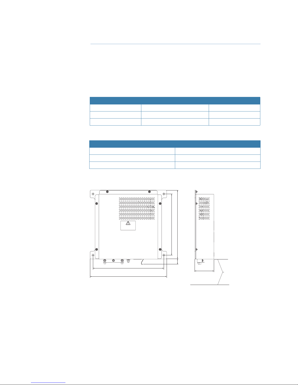
SRT adapter box dimensions
WARNING
HIGH VOLTAGE IS PRESENT INSIDE
COVER MUST BE OPEN BY
SKILLED PERSONNEL ONLY
370
400
116
300
(min. distance to the oor)
28 360
320
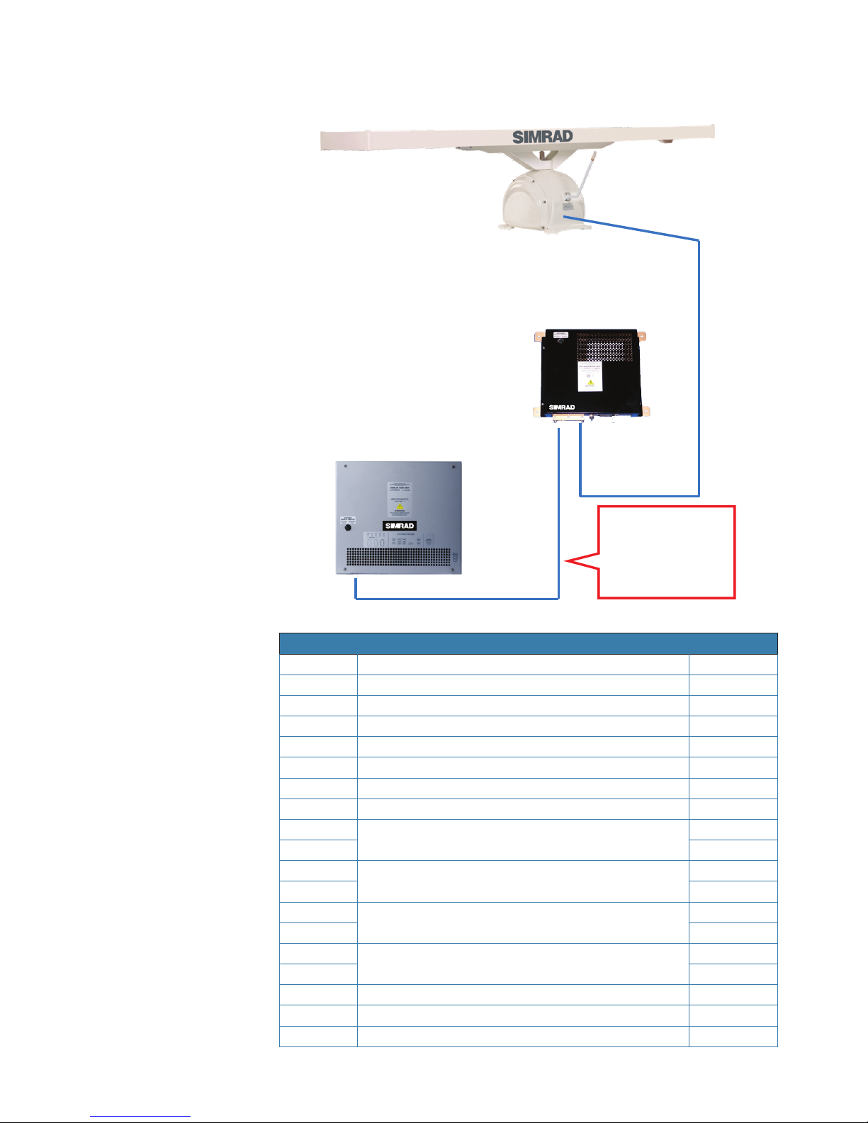
Installation
The SRT module must be installed in between the Core unit and the S-band SRT 30 KW
up-mast HSC, part number 000-13193-001, unit type UPMAST/S-002.
It must be installed in a protected area close to the Core unit.
Page 3
| 3
S-band HSC SRT Adapter Box | Installation Guide Addendum
The following block diagram displays the S-band in configuration HSC:
AB + CD= Standard Up Mast
Cable
15 m: 000-10332-001
30 m: 000-10333-001
60 m: 000-10334-001
A
B
C
D
Cable composition
NUMBER CABLE TYPE COLOR
1 RG59 coaxial Black
2 RX174 coaxial Black
3 1.5 mm2 single core Red
4 1.5 mm2 single core Black
5 2.5 mm2 single core Red
6 2.5 mm2 single core Black
7 2.5 mm2 single core Green/Yellow
8
2 x 0.35 mm
2
shielded twisted pair
Blue
9 Black
10
2 x 0.35 mm2 shielded twisted pair
White
11 Black
12
2 x 0.35 mm2 shielded twisted pair
Green
13 Black
14
2 x 0.35 mm2 shielded twisted pair
Red
15 Black
16 0.35 mm
2
single core White
17 0.35 mm2 single core Blue
18 0.35 mm2 single core Red
Page 4

4 |
S-band HSC SRT Adapter Box | Installation Guide Addendum
Cable wiring legend
Cables no. 5 and 6 are dedicated to the Motor power supply. The purpose of these installation
instructions is to identify the wires inside the cable and connect to the new power supply.
Tools Needed
• Cutter
• Plastic cable ties
• 5.5 mm hexagonal
• 5 mm Allen key
• 10 mm flat spanner
• Phillips screwdriver
• Scissors and tongs AMP mod2
Wiring procedure
For installation you need 50 cm of free cable.
“C” cable to SRT up mast
S-band pedestal
Cable from core unit “B”
Page 5

| 5
S-band HSC SRT Adapter Box | Installation Guide Addendum
1 Remove the isolation rubber and prepare the cable as in Fig. 6, 13, 14 and 15.
2 Find the red and the black 2.5 mm wires.
3 At the entrance of Point B make a cut 10 cm away from the gland and isolate as in Fig. 9 and Fig.12.
4 Connect the cable shields in the cable gland as in Fig. 12, 14 and 15.
5 Connect the black cable on the negative screws of the Power supply as in Fig. 17.
6 Connect the red wires on 2T1 of relay K1 as in Fig. 18.
7 If an external safety control switch is needed, open the link as in Fig.19 and connect the external switch.
¼ Note: Fig.8 shows four black cables. Make sure to identify the RX174 coaxial, the RG59 coaxial,
the 1.5 mm wire and the 2.5 mm wire.
Fig. 1
Open the SRT box.
Fig. 2
Check the cable length.
Fig. 3
Prepare the cable.
Fig. 4
Min 40 cm, Max 70 cm.
Fig. 5 Fig. 6
Shield connection.
Page 6

6 |
S-band HSC SRT Adapter Box | Installation Guide Addendum
Fig. 7
2.5 mm red wires.
Fig. 8
2.5 mm black wires.
Fig. 9
Isolate the active 48 V wire coming
from the core unit.
Fig. 10
Open the cable gland (5.5 mm).
Fig. 11
Use the 10 mm flat spanner.
Fig. 12
Insert cable C.
Fig. 13
Close with cable B and tighten.
Fig. 14
Insert all cables into the slot.
Fig. 15
Close and tighten.
Page 7

| 7
S-band HSC SRT Adapter Box | Installation Guide Addendum
Fig. 16
2.5 mm red and black wires.
Fig. 17
Black on GND P.S.
Fig. 18
Red on antenna safety relay.
Fig. 19
Link for external switch.
Testing and commissioning
1 Connect the 220 V power supply to the SRT adapter box.
2 Switch on the unit’s main switch.
3 Connect a test lead to relay pin 2T1. GND must be present + 48 VDC +- 15%.
4 Close the box and test the S-band antenna at HSC speed.
Page 8

*988-11129-001*
www.navico-commercial.com
 Loading...