

Page 1
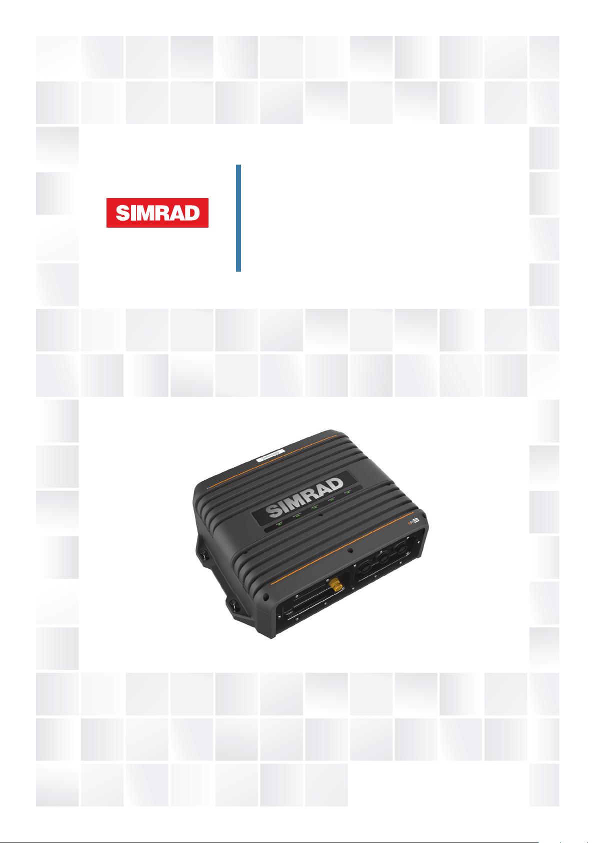
S5100 Sonar module
Installation manual
ENGLISH
simrad-yachting.com
Page 2

Page 3

Preface
Disclaimer
As Navico is continuously improving this product, we retain the right to make changes to the
product at any time which may not be reflected in this version of the manual. Please contact
your nearest distributor if you require any further assistance.
It is the owner’s sole responsibility to install and use the equipment in a manner that will not
cause accidents, personal injury or property damage. The user of this product is solely
responsible for observing maritime safety practices.
NAVICO HOLDING AS AND ITS SUBSIDIARIES, BRANCHES AND AFFILIATES DISCLAIM ALL
LIABILITY FOR ANY USE OF THIS PRODUCT IN A WAY THAT MAY CAUSE ACCIDENTS, DAMAGE
OR THAT MAY VIOLATE THE LAW.
This manual represents the product as at the time of printing. Navico Holding AS and its
subsidiaries, branches and affiliates reserve the right to make changes to specifications
without notice.
Governing Language
This statement, any instruction manuals, user guides and other information relating to the
product (Documentation) may be translated to, or has been translated from, another
language (Translation). In the event of any conflict between any Translation of the
Documentation, the English language version of the Documentation will be the official
version of the Documentation.
Copyright
Copyright © 2016 Navico Holding AS.
Warranty
The warranty card is supplied as a separate document.
In case of any queries, refer to the brand website of your display or system: www.simrad-
yachting.com.
Compliance statements
This equipment complies with:
• CE under EMC directive 2014/30/EU
• The requirements of level 2 devices of the Radio communications (Electromagnetic
Compatibility) standard 2008
The relevant Declaration of conformity is available in the product's section at the following
website: www.simrad-yachting.com.
About this manual
Intended audience
This manual is a reference guide for installing the S5100. The manual is written for marine
electronics technicians, and assumes some prior knowledge and skills relevant to the type of
work to be carried out.
Important text conventions
Important text that requires special attention from the reader is emphasized as follows:
Note: Used to draw the reader’s attention to a comment or some important information.
Ú
Warning: Used when it is necessary to warn personnel that they should
proceed carefully to prevent risk of injury and/or damage to equipment/
personnel.
Preface | S5100 Installation Manual
3
Page 4

Trademarks
Navico® is a registered trademark of Navico.
Simrad® is used by license from Kongsberg.
NMEA® and NMEA 2000® are registered trademarks of the National Marine Electronics
Association.
4
Preface | S5100 Installation Manual
Page 5

Contents
6 Introduction
6 Overview
6 Parts included
7 Connectors and LED location
8 Installation
8 Mounting location
8 Transducer installation
9 Wiring
9 Guidelines
9 Grounding the unit
10 Power connection
11 Connecting the S5100 to MFD systems
12 Transducer connection
14 Troubleshooting
14 LED indicators
15 Maintenance
15 Preventive maintenance
15 Checking the connectors
15 Software update
16 Spare parts and accessories
16 S5100 Spare parts and accessories
16 Transducers
17 Technical specifications
17 S5100
18 Dimensional drawings
18 S5100
Contents | S5100 Installation Manual
5
Page 6
Introduction
ENGLISH
Install
ati
on Manual
bandg.
co
m
E
NGL
I
S
H
Installati
on
Manual
bandg.
co
m
1
2
8
3
4
5
6
7
1
Overview
The S5100 is a networked triple CHIRP module including 3 independent sonar channels. This
allows for simultaneous use of High, Medium and Low CHIRP, and for dual independent
ranges on a single screen. In addition, each frequency range can be viewed on connected
MFDs in the network.
The module is compatible with a variety of Navico's Multi-Function Displays (MFDs). See
more details on the S5100 website on www.simrad-yachting.com.
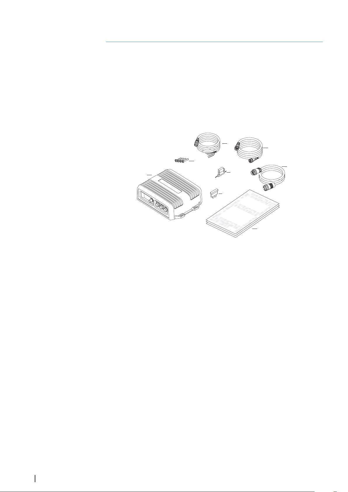
Parts included
1 S5100 unit
2 (4x) Fixing screws, Phillips stainless steel, 25 mm (1")
3 Power cable, 2 m (6.5 ft)
4 Ethernet cable, 1.8 m (6 ft)
5 (3x) 7 to 9 pin adapter cables, 0.6 m (2 ft)
6 Fuse holder
7 Fuse, 5 Amp
8 Documentation pack
6
Introduction | S5100 Installation Manual
Page 7

Connectors and LED location
1
2
3
65 7
4
1 Power connector
2 Grounding screw
3 LED status indicators
4 Ethernet connector
5 Sonar channel 1
6 Sonar channel 2
7 Sonar channel 3
Introduction | S5100 Installation Manual
7
Page 8

Installation
2
Mounting location
Choose the mounting locations carefully before you drill or cut.
For overall width and height requirements, refer to "Dimensional drawings" on page 18.
Do not mount any part where it can be used as a hand hold, where it might be submerged,
or where it will interfere with the operation, launching, or retrieving of the boat.
The unit should be mounted so that the operator can easily see the LED status indicators.
Check that it is possible to route cables to the intended mounting location.
Leave sufficient clearance to connect all relevant cables.
The unit can be mounted on a horizontal or on a vertical surface. Create drip loops when the
unit is mounted on a vertical surface with connections exiting upwards.
Before cutting a hole in a panel, make sure that there are no hidden electrical wires or other
parts behind the panel.
Ensure that any holes cut are in a safe position and will not weaken the boat’s structure. If in
doubt, consult a qualified boat builder, or marine electronics installer.
Note: Where flush mounted, the enclosure should be dry and well ventilated. In small
Ú
enclosures, it may be required to fit forced cooling.
Warning: Inadequate ventilation and subsequent overheating of the unit
may cause unreliable operation and reduced service life. Exposing the unit
to conditions that exceeds the specifications could invalidate your warranty.
– refer to "Technical specifications" on page 17.
Transducer installation
For transducer installation information, refer to separate installation instructions included
with the transducer.
8
Installation | S5100 Installation Manual
Page 9

Wiring
3
Guidelines
Don't:
• make sharp bends in the cables
• run cables in a way that allows water to flow down into the connectors
• run the data cables adjacent to radar, transmitter, or large/high current carrying cables or
high frequency signal cables.
• run cables so they interfere with mechanical systems
Do this:
• make drip and service loops
• use cable-tie on all cables to keep them secure
• solder/crimp and insulate all wiring connections if extending or shortening the cables.
Extending cables should be done with suitable crimp connectors or solder and heat
shrink. Keep joins as high as possible to minimize possibility of water immersion.
• leave room adjacent to connectors to ease plugging and unplugging of cables
Warning: Before starting the installation, be sure to turn electrical power
off. If power is left on or turned on during the installation, fire, electrical
shock, or other serious injury may occur. Be sure that the voltage of the
power supply is compatible with the unit.
Warning: The positive supply wire (red) should always be connected to
(+) DC with the supplied fuse or a circuit breaker (closest available to fuse
rating).
Grounding the unit
For additional safety, install grounding cable in ground screw hole as indicated on the
illustration. Recommended 16 awg wire.
Wiring | S5100 Installation Manual
9
Page 10

Power connection
3
4
1
2
1
2
3
4
12 - 24 V DC
+
_
4
1
3
2
(n/c)
12 - 24 V DC
2
1
3
4
4 1
3
+
_
2
(n/c)
5
The unit is designed to be powered by a 12 or 24 V DC system. It is protected against reverse
polarity, under voltage and over voltage (for a limited duration).
Unit socket (male)
Key Purpose Color
1 DC negative Black
2 Not used Blue
3 Power control Yellow
4 +12/24 V DC Red
Cable plug (female)
Power control
The unit has no power key and will turn on when power is applied.
If the unit is connected directly to the vessel’s battery, the module will continue to draw
power even when it is not in operation. It is recommended that the yellow power cable wire
be fitted with an optional on/off switch, allowing the unit to be powered off when not in use.
10
Some MFD systems can be configured for power control. When the S5100 is used in such
systems it is recommended to connect the unit to the power control bus and set the MFD to
power control master. Refer to your MFD documentation for more information.
Key Purpose Color
1 DC negative Black
2 Not connected Blue
3 Power control Yellow
4 +12/24 V DC Red
5 Power control bus
Wiring | S5100 Installation Manual
Page 11

Connecting the S5100 to MFD systems
1
2
3
4
5
2
3
1
4
5
A
B
C
The S5100 connects to your MFD system over the Ethernet network.
Unit socket (female)
Key Purpose Color
1 Transmit positive TX+ Blue/White
2 Transmit negative TX- Blue
3 Receive positive RX+ Orange/White
4 Receive negative RX- Orange
5 Shield Bare
The illustration shows:
• how the S5100 connects to a single MFD (A), and how MFDs with two Ethernet
connectors can daisy chain (B) to share sonar data
• how sonar data from the S5100 can be shared by connecting the MFDs via a network
expansion port (C)
Cable plug (male)
Wiring | S5100 Installation Manual
11
Page 12

Transducer connection
A
Warning: Removing the transducer cables from the S5100 while the
module is powered on can cause sparks that can damage the S5100
transmitter as well as the transducers. Remove the transducer cables only
after the module has been disconnected from its power source.
Transducers with 9 pin connector
Up to three 9 pin transducers can be connected directly to any of the sonar channels on the
S5100.
One 9 pin transcuder can be connected to the remaining open channel after a dual
connector transducer has been attached.
Transducers with 7 pin connector
Transducers with a blue 7 pin connector must be connected to S5100 by using the 7-9
adapter cable. 3 of these adapter cables are included in the box.
The adapter cable connects to any of the sonar channels.
Transducers with bare wires
Transducers with bare wires must be connected to the S5100 via the optional Junction box
(A) (part number 000-13262-001).
The Junction box cable connects to the sonar channels as follows:
• single frequency transducers: to any of the sonar channels
• dual frequency transducers: to Channel-1 and Channel-2, or to Channel-2 and Channel-3
as described in "Transducers with two connectors" on page 13
12
Detailed installation description and wiring diagram is included with the junction box.
Wiring | S5100 Installation Manual
Page 13

Transducers with two connectors
A B A B
A B B A
When using transducers with two connectors:
• connect the high frequency element connector (A) to the Channel-1 or Channel-2 plug
• connect the low frequency element connector (B) to the plug to the immediate right of
the plug used for the high frequency connector.
Wiring | S5100 Installation Manual
13
Page 14

Troubleshooting
POWER NETWORK CHANNEL-1 CHANNEL-2 CHANNEL-3
4
LED indicators
5 LEDs on the unit's cover indicate status for the S5100, for the network and for connected
transducers.
Power LED
• OFF
- No power connection
• Check power and power cable
• Check yellow wire
• ON - Red
- System starting
• ON - Green
- System operational
• FLASHING - Red/Green
- Software error or unit reprogrammed
• Restart the unit
• If still not ok, contact Customer Support
Network LED
• OFF
- No Ethernet connection
• Check cable
• ON - Green
- Ethernet connected and ok
Sonar LEDs
• OFF
- Transducer not connected
• FLASHING every 0.5 second - Red
- Initializing transmitter
• FLASHING every second - Green
- Searching for bottom signal
• ON - Green
- System operational
14
Troubleshooting | S5100 Installation Manual
Page 15

Maintenance
5
Preventive maintenance
The unit does not contain any field serviceable components. Therefore, the operator is
required to perform only a very limited amount of preventative maintenance.
Checking the connectors
The connectors should be checked by visual inspection only.
Push the connector plugs into the connector. If the connector plugs are equipped with a
lock, ensure that it is in the correct position.
Software update
You can update the software for the S5100 from a display unit connected to the network.
Software version can be viewed on the Echosounder page when the S5100 is selected as the
sonar source.
Software version can also be viewed from the Sonar Installation dialog when one of the
S5100
channels is selected as the source.
The latest software is available for download from the product website.
1. Download the latest software and save it to a memory card
2. Insert the memory card to the display unit
3. Start the File explorer, and select the update file on the memory card
4. Start the update from the file details dialog
5. Remove the memory card when the update is completed
The dialog image examples are from a Simrad MFD.
Maintenance | S5100 Installation Manual
15
Page 16

6
Spare parts and accessories
The most up-to-date list of spare parts and accessories is available at the product site on
www.simrad-yachting.com.
S5100 Spare parts and accessories
Item Part number
Power cable, length 1.8 m (6 ft) 000-00128-001
Ethernet cable yellow 5 Pin, 2 m (6.5 ft) 000-0127-51
Ethernet cable yellow 5 Pin, 4.5 m (15 ft) 000-0127-29
Ethernet cable yellow 5 Pin, 7.7 m (25 ft) 000-0127-30
Ethernet cable yellow 5 Pin, 15.2 m (50 ft) 000-0127-37
Junction box with adapter cable for bare wire transducers 000-13262-001
7 to 9 pin adapter cable for 7 pin Airmar transducers 000-13313-001
Transducers
For a full list of compatible transducers please refer to the transducer selection guide on
http://www.simrad-yachting.com/transducerguide/.
16
Spare parts and accessories | S5100 Installation Manual
Page 17

7
Technical specifications
Note: The most up-to-date specifications list is available at: www.simrad-yachting.com
Ú
S5100
Approvals
Compliance EMC directive 2014/30/EU
Standard IEC 60945
Connectivity
Transducer 3 x 9-pin sonar connectors
Ethernet 1 x 100 Mbps
Power 1 x 4-pins power connector
Electrical
Supply voltage - Operating 9-32 V DC
Supply voltage - OFF to ON 10.4 - 31.2 V DC
Power consumption - Max 85 W
Recommended fuse rating 5 Amp
Environmental
Operating temperature range -15°C - +55°C (5°F - 131°F)
Storage temperature -30°C - +70°C (-22°F - 158°F)
Waterproof rating IPx5
Humidity Up to 95% at 35°C (95°F) non-condensing
Shock and vibration Acc to IEC 60945
Physical
Dimensions See "Dimensional drawings" on page 18
Weight 4.7 kg (10.4 lbs)
Compass Safe Distance 1.8 m (6 ft)
Sonar specification
Power output 600 W - 3 kW RMS (dependent on
transducer)
Frequencies 25 - 250 kHz
Transmitter and receiver type 3 tuned CHIRP transmitters
3 Broadband tuned receivers
Warranty Period 2 years
Technical specifications | S5100 Installation Manual
17
Page 18

Dimensional drawings
109 mm (4.277”)
320 mm
(12.597”)
340 mm
(13.385”)
250 mm (9.842”)68 mm
(2.673”)
60 mm
(2.344”)
100 mm
(3.94”)
8
S5100
18
Dimensional drawings | S5100 Installation Manual
Page 19

Page 20

*988-11152-001*
 Loading...