

Page 1

ENGLISH
S3009 Navigation Echo Sounder
User Manual
www.navico-commercial.com
Page 2

Page 3

Preface
Disclaimer
As Navico is continuously improving this product, we retain the right to make changes to the
product at any time which may not be reflected in this version of the manual. Please contact
your nearest distributor if you require any further assistance.
It is the owner’s sole responsibility to install and use the equipment in a manner that will not
cause accidents, personal injury or property damage. The user of this product is solely
responsible for observing maritime safety practices.
NAVICO HOLDING AS AND ITS SUBSIDIARIES, BRANCHES AND AFFILIATES DISCLAIM ALL
LIABILITY FOR ANY USE OF THIS PRODUCT IN A WAY THAT MAY CAUSE ACCIDENTS, DAMAGE
OR THAT MAY VIOLATE THE LAW.
This manual represents the product as at the time of printing. Navico Holding AS and its
subsidiaries, branches and affiliates reserve the right to make changes to specifications
without notice.
Governing language
This statement, any instruction manuals, user guides and other information relating to the
product (Documentation) may be translated to, or has been translated from, another
language (Translation). In the event of any conflict between any Translation of the
Documentation, the English language version of the Documentation will be the official
version of the Documentation.
Copyright
Copyright © 2018 Navico Holding AS.
Warranty
The warranty card is supplied as a separate document. In case of any queries, refer to the
brand website of your unit or system:
www.navico.com/commercial.
Compliance statements
Regulatory compliance
Navico declare under our sole responsibility that the S3009 conforms with the requirements
of:
• the requirements of level 2 devices of the Radio communications (Electromagnetic
Compatibility) standard 2008 - RCM
• the European Council Directive 2014/90/EU on Marine Equipment modified by
Commissioning Directive (EU) 2017/306 - Wheelmark
All compliance documents are available on the product's section on the following website:
www.navico.com/commercial.
Technical compliance
The S3009 meets the requirements of the following standards:
• NMEA 0183/IEC61162-1 ed.5
• NMEA 2000/IEC61162-3
• ISO 9875:2000/Cor 1:2006
• IEC62288 ed.2
• IEC60945 ed.4
Preface | S3009 Echo Sounder User Manual
3
Page 4
About this manual
Important text conventions
Important text that requires special attention from the reader is emphasized as follows:
Ú
Note: Used to draw the reader’s attention to a comment or some important information.
Warning: Used when it is necessary to warn personnel that they should
proceed carefully to prevent risk of injury and/or damage to equipment/
personnel.
Intended audience
This manual is written for system operators and installers. It assumes that the user has basic
knowledge of echosounders, and assumes some knowledge and skills relevant to installation
of transducers and echosounder equipment.
Software versions
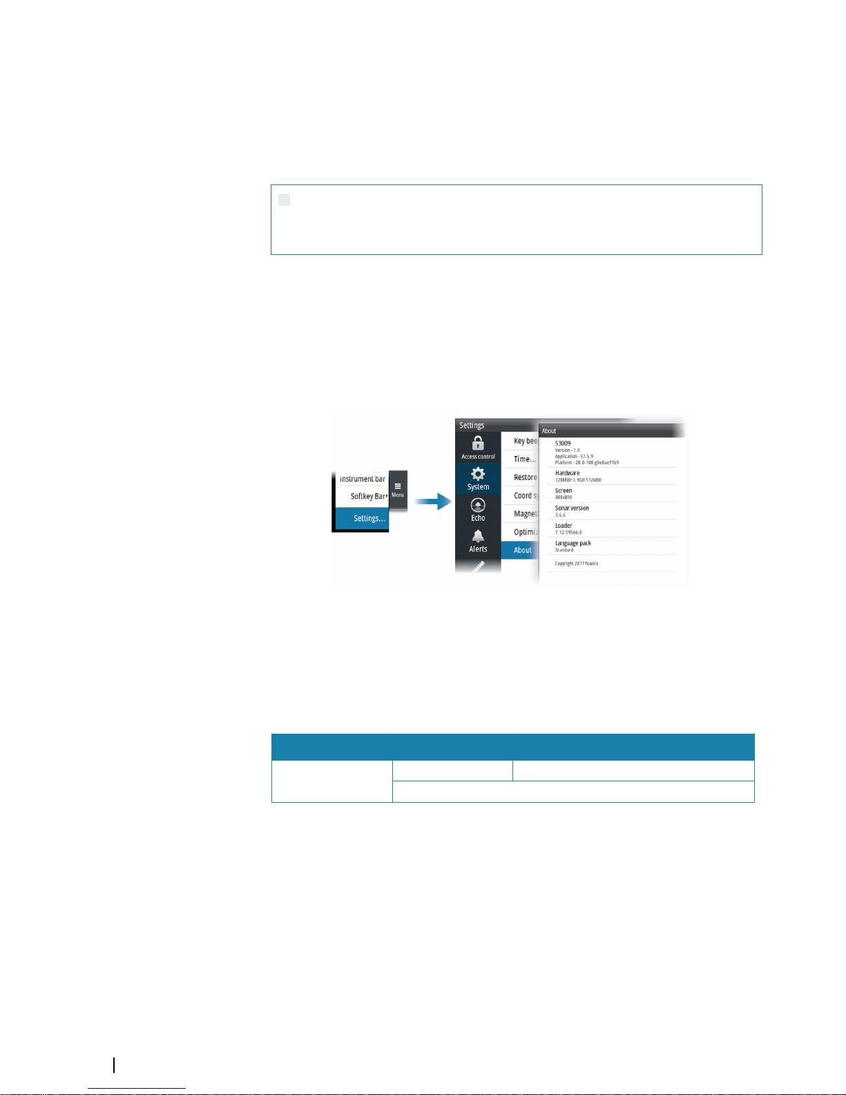
You can view the software version from the About dialog:
Ú
Note: The image above is an example only.
The manual will continuously be updated to match new software releases. The latest
available manual version can be downloaded from the product website on:
www.navico.com/commercial.
Change log
Part no Date Approved by
988-12043-001
4. Jan 2018 Jarl Gaute Vartdal
First version
4
Preface | S3009 Echo Sounder User Manual
Page 5

Viewing the manual on the screen
The PDF viewer included in the unit makes it possible to read the manuals and other PDF
files on the screen. The manuals can be read from a card inserted in the card reader or copied
to the unit’s internal memory.
Use the keys to maneuver in the PDF file as described below:
• Scroll pages
Use the rotary knob.
• Zoom in/out
Use the + and - keys.
• Maneuver on a page that is larger than the display area
Use the arrow keys.
• Exit the PDF viewer
Use the Exit key.
Trademarks
Navico® is a registered trademark of Navico.
Simrad® is used by license from Kongsberg.
NMEA® and NMEA 2000® are registered trademarks of the National Marine Electronics
Association.
SD™ and microSD™ are trademarks or registered trademarks of SD-3C, LLC in the United
States, other countries or both.
Preface | S3009 Echo Sounder User Manual
5
Page 6

Contents
8 Introduction
8
The S3009 Navigation Echo Sounder system
8 System components
8 System examples
9 The user interface
9 Front panel and keys
10 The main panel
10 Softkeys
11 The menu system
11 On-screen keyboard
12 Basic operation
12 Turning the system on and off
12 Adjusting display brilliance
12 Acknowledging alerts
12 Adjusting depth settings
13 Zooming the image
13 Using the cursor on the image
14 Viewing the depth history
15 Setting up the echosounder image
15 Setting the range
15 Adjusting color and gain settings
16 Display time
16 Optional image items
16 Advanced options
18 Panel setup
18 Selecting transducer source
18 Split screen options
19 Show or hide the softkey bar
19 Edit the content of the Instrument bar
20 Advanced options
20 Recording depth data
20 Managing files
20 Simulator
21 Data logging
21 Depth log
21 Alert log
21 NMEA 0183 data log
21 Exporting the log files
22 The alert system
22 Type of alerts
22 Alert notifications
23 The Alerts dialog
23 Alphabetic alert list
24 Mounting
24 S3009 Control unit
25 Transducers
25 S5100 echosounder module
6
Contents | S3009 Echo Sounder User Manual
Page 7

26 Wiring
26
Guidelines
26 System examples
27 Transducer wiring
32 Power wiring
34 Ethernet wiring
34 NMEA 0183 wiring
35 NMEA 2000 wiring
36 External alarm wiring
38 Software setup
38 Software setup sequence
38 Accessing the settings dialog
38 Access control
38 System settings
39 Echo settings
41 Units settings
41 Network settings
45 Maintenance
45 Preventive maintenance
45 Cleaning the display unit
45 Cleaning the media port door
45 Checking the keys
45 Checking the connectors
45 Software upgrades
46 Backing up your system data
47 Appendix
47 Menu overview
49 Dimensional drawings
51 Supported data
54 Technical specifications
Contents | S3009 Echo Sounder User Manual
7
Page 8

Introduction
The S3009 Navigation Echo Sounder system
The S3009 Navigation Echo Sounder system is a type approved echosounder system
conforming to the International Maritime Organization (IMO) requirements for equipment
installed on vessels that are subject to SOLAS regulations. The system is type approved only
in the configuration specified in the certificate.
The type approval certificate is available at the product web site: www.navico.com/
commercial.
System components
S3009 Control unit
The S3009 is a dedicated echosounder control unit with a 9-inch portrait display. The unit is
fitted with a high brightness screen, suited for pilothouse installation.
Transducers
The system is certified with the following transducers:
• TGM50-200-xxL (200 kHz)
• TGM60-50-xxL (50 kHz)
S5100 Echosounder module
The S5100 is a networked echosounder module with 3 independent echosounder channels.
System examples
For system wiring examples refer to "System examples" on page 26.
1
8
Introduction | S3009 Echo Sounder User Manual
Page 9
The user interface
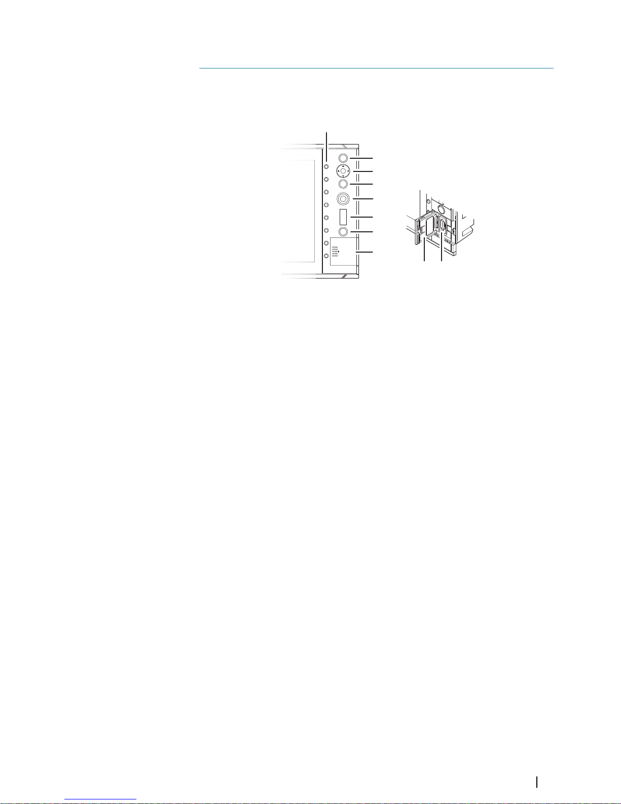
Front panel and keys
1
2
3
4
5
6
7
8
8 9
1 Softkeys
Press a key once to access the corresponding function shown on the display.
2 ENT (Enter) key
With no menu or no cursor active: no function.
Menu operation: press to select or deselect an option.
3 Arrow keys
With no menu active: press to activate the cursor and to move the cursor on the
image.
Menu operation: press to navigate through menu items and to adjust a value.
4 EXIT key
With no menu or no cursor active: no function.
With cursor active: press to remove cursor.
Menu operation: press to return to previous menu level or to exit a dialog.
5 Rotary knob
With no menu active: behavior depending on operational mode.
Menu operation: rotate to scroll through menu items and to adjust values. Press to
select or to save settings.
On dual split panel: press to switch focus between the panels.
6 RANGE key
Press the + or the - indication to increase or decrease the range.
7 Power key
Press once to turn the system on.
When the system is running: press once to display the Brilliance pop-up.
Press and hold to display the Power off pop-up.
8 Card reader door
9 SD card reader
2
The user interface | S3009 Echo Sounder User Manual
9
Page 10
The main panel
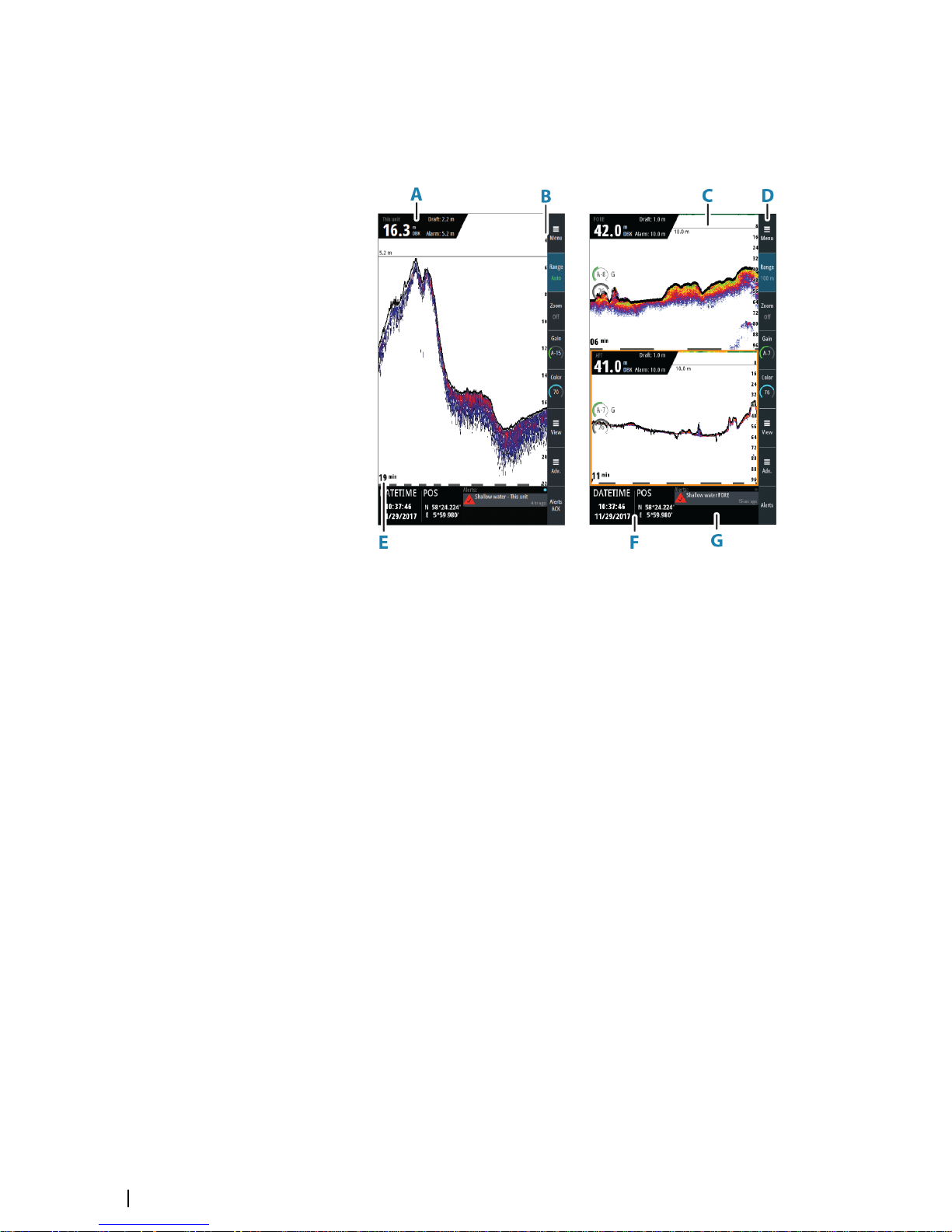
The main panel is divided into predefined areas.
The panel can be set up as a single panel or as different split panels. Refer to "Panel setup" on
page 18.
A Echosounder information panel
Current depth, source name, draft setting and alarm limit for active transducer
B Depth scale
Depth scale indication
C Depth alarm line
Visual indication of depth alarm setting
D Softkey bar
Indication of softkey function
E Data time scale
Time of depth history shown on the display
F Instrument bar
Two configurable data gauges
G Alerts panel
List of active alerts
Softkeys
When a softkey is pressed, the function for the selected softkey becomes available.
By default, the softkey bar is displayed on the panel. You can hide the softkey bar so that
more of the image is displayed. Refer to "Show or hide the softkey bar" on page 19.
More details about the softkey functionality are available in the separate sections describing
the functions later in this manual.
Softkey pop-ups
If you press the Range or Gain softkey twice, their corresponding pop-up is displayed.
10
The user interface | S3009 Echo Sounder User Manual
Page 11
If a pop-up has more than one option, you select the options by using the arrow keys.
You close the pop-up by re-pressing the softkey or by pressing the Exit key.
The menu system
The Menu, View and Advanced softkeys display menus.
• Use the up and down arrow keys or turn the rotary knob to move up and down in a menu
• Press the Enter key, the right arrow key or the rotary knob to access a sub menu, to toggle
options or to confirm a selection
• Press the Exit key or the left arrow key to return to previous menu level and then exit the
menu system
Main menu and sub menus
You access the Main menu by pressing the Menu softkey.
A selected menu item is indicated with a blue background. If a sub-menu is available, this is
indicated with a right arrow after the text.
Some options display a slider. Turn the rotary knob or press the up/down arrow keys to
adjust the value.
Settings dialogs
The various Settings dialogs provide access to system settings.
You access the Settings dialogs from the Main menu.
Ú
Note: Some of the parameters in the Settings dialogs are intended for system setup and
service engineers. These parameters are protected, and they are only available by
entering the password QWERTY in the Access control dialog.
There is no time-out for the Settings dialogs. A dialog remains open until it is manually
closed.
For more information about the Settings dialogs, refer to "Software setup" on page 38.
On-screen keyboard
A numeric or alphanumeric virtual keyboard is displayed when required to enter user
information in dialogs.
• Select a virtual key by using the arrow keys followed by the Enter key to confirm the
selection
• Complete the entry and close the dialog by selecting the Enter virtual key
You remove the virtual keyboard without entering information by pressing the Exit key.
The user interface | S3009 Echo Sounder User Manual
11
Page 12
Basic operation
Turning the system on and off
The unit is turned on by pressing the Standby/Brilliance key.
Press and hold the Standby/Brilliance key to turn the unit off.
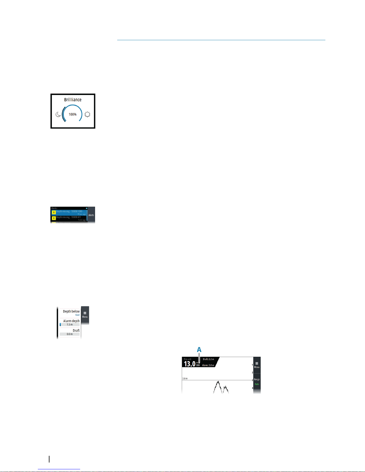
Adjusting display brilliance
The brilliance is adjusted from the Brilliance pop-up.
• Display the pop-up by pressing the Standby/Brilliance key, then adjust the display
brilliance by turning the rotary knob.
At first start-up, the display brilliance is set to 100%. When the unit is restarted, the brilliance
is automatically set to the level it was prior to switching the unit off.
The system includes a Day and a Night color palette. When the brilliance is set to 40% or
lower, the system switches to use the night palette.
• With the pop-up open, you switch between Day and Night palette by pressing the left
(40%) or right (100%) arrow keys.
You close the pop-up by pressing the Exit key.
Acknowledging alerts
The Alerts softkey is labelled Alerts Acknowledge (Alerts Ack on smaller screens) if there is an
unacknowledged alarm or warning in the system.
Acknowledge the most recent alert by pressing the Alerts softkey.
• Repeat pressing this softkey to continue to acknowledge alerts from the top of the Alerts
panel.
• Press the Exit key to exit the Alerts panel.
When an alert is acknowledged, the alert icon stops flashing and changes to the
acknowledged icon. The siren continues to sound if there are remaining unacknowledged
alerts, otherwise it is muted.
The acknowledged alert is not moved to its new position in the sort order until there has
been 2 seconds without any alerts being acknowledged.
For more details, refer to "The alert system" on page 22.
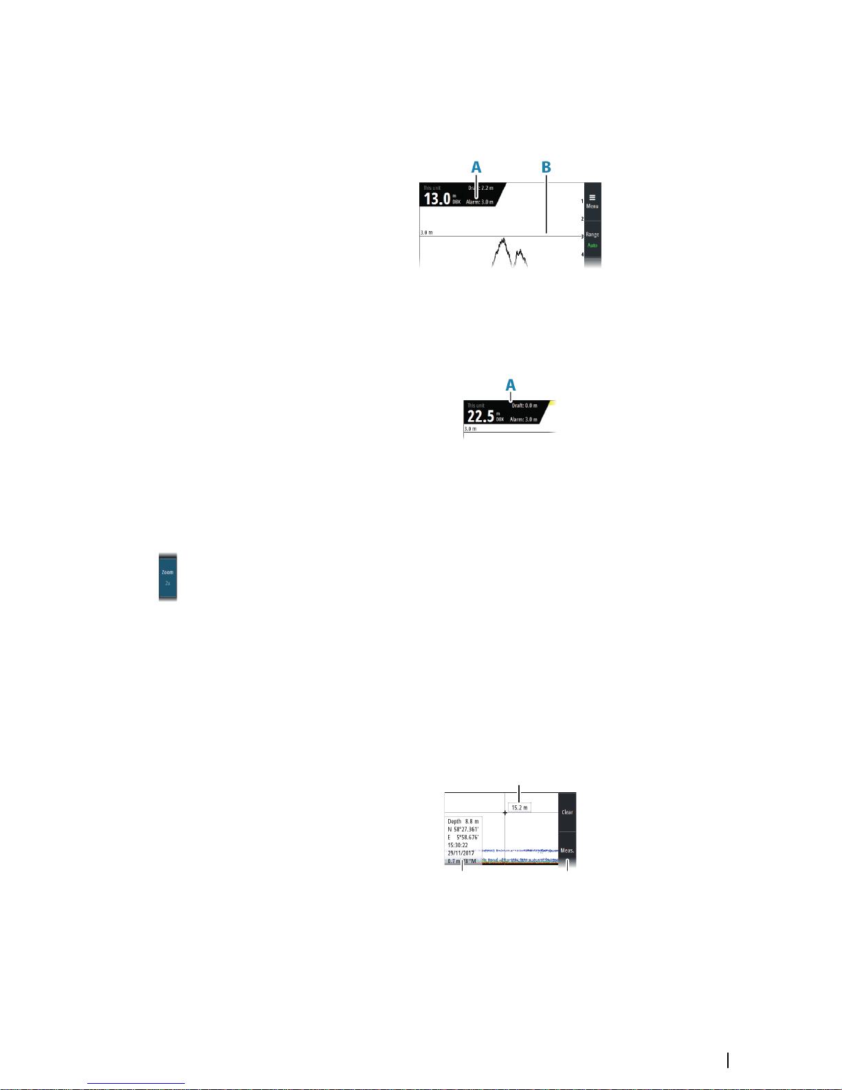
Adjusting depth settings
The depth reference
You can show the depth referenced to the surface, the keel or to the transducer.
The depth reference is indicated in the echosounder information panel (A) as either DBS
(Depth Below Surface), DBK (Depth Below Keel) or as DBT (Depth Below Transducer).
3
12
Basic operation | S3009 Echo Sounder User Manual
Page 13
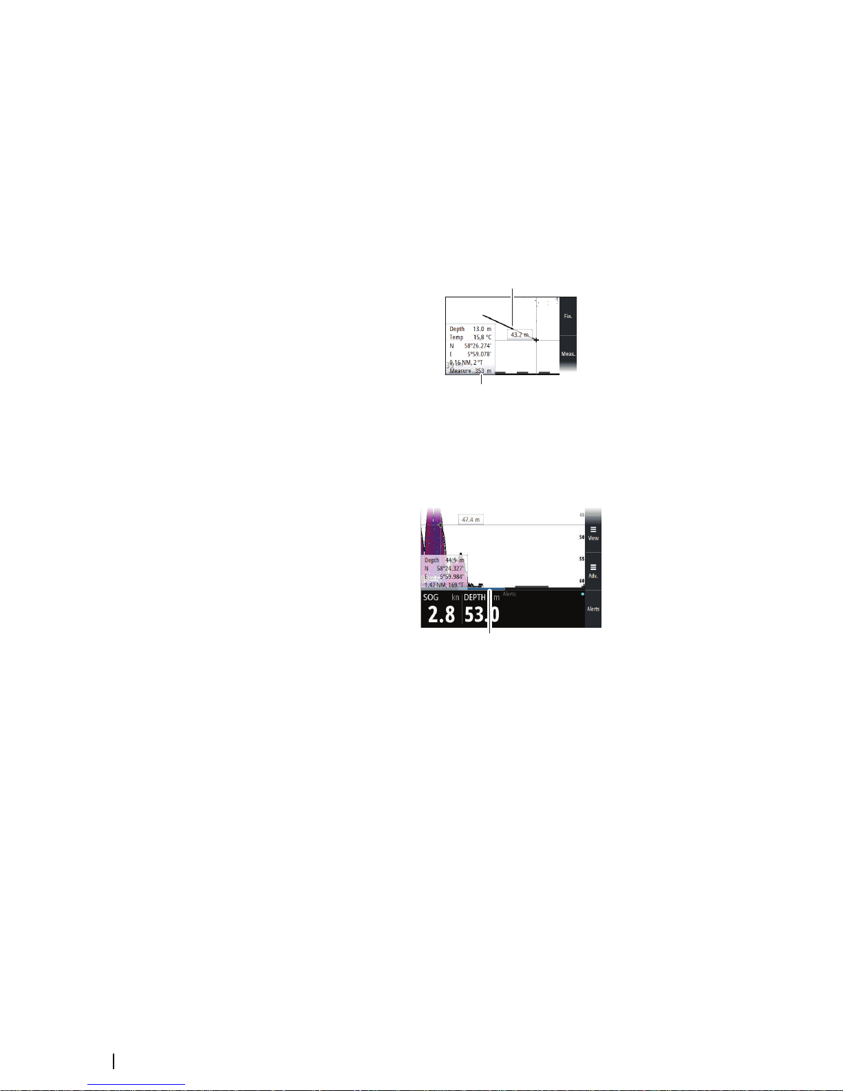
Alarm depth
An alarm is generated if the measured depth becomes shallower than the set alarm limit.
The depth alarm limit is indicated in the echosounder information panel (A), and a horizontal
line (B) indicates the depth settings on the image.
The alarm depth is always shown with the same reference as the measured depth.
Draft
The draft setting can be adjusted for different sailing and load conditions.
The draft value is indicated in the echosounder information panel (A).
Ú
Note: If dual panels are used, the draft value can be set individually for each panel.
Zooming the image
You zoom the image by pressing the Zoom softkey and then turning the rotary knob. You
can pan the zoomed area with the arrow keys.
The zoom level is shown in the Zoom softkey.
You can also zoom the image by using the Split Zoom option. Refer to "Split screen options" on
page 18.
Using the cursor on the image
You activate the cursor by pressing any arrow key. Use the arrow keys to move the cursor on
the image.
When the cursor is active, the depth at the cursor position is displayed (A), and the cursor
information window (B) is activated. The two upper softkeys (C) change to show cursor
relevant options.
To remove the cursor and cursor elements from the panel, press the Clear softkey or the Exit
key.
A
B C
Basic operation | S3009 Echo Sounder User Manual
13
Page 14
Measuring distance
The cursor can be used to measure the distance between the position of two observations
on the image.
1. Position the cursor on the point from where you want to measure the distance
2. Start the measuring function by pressing the Meas. softkey
3. Position the cursor on the second measuring point
-
A line (A) is drawn between the measuring points, and the distance (B) listed in the
Cursor Information window
4. Press the Enter key to switch reference point to cursor position
5. Continue selecting new measuring points if required
Press the Fin softkey to exit the measurement feature.
A
B
Viewing the depth history
Whenever the cursor is active, the history scroll bar is shown at the bottom of the image (A).
The history bar shows the image you are currently viewing in relation to the total depth
history stored.
A
• Use the arrow keys to pan the image to show image history.
To resume normal scrolling, press the Clear softkey or the Exit key.
14
Basic operation | S3009 Echo Sounder User Manual
Page 15

Setting up the echosounder image
Setting the range
The system includes a manual and an automatic range mode.
• In manual mode, the depth range can be set independent of the depth of the water. You
can select a preset range level or define a custom range
• In auto mode, the system automatically displays the whole range from the water surface
to the bottom
Ú
Note: Setting a deep manual range in shallow water may cause the system to lose track
of the depth.
Preset range levels
Select a preset range level manually by:
• using the + and - icons on the Range key
• pressing the Range softkey once, and then turning the rotary knob
Auto range
In auto range, the system automatically displays the whole range from the water surface to
the bottom.
Select Auto range by:
• pressing the Range softkey twice to display the pop-up, and then selecting the Auto
option
• pressing and holding the Range softkey to toggle the Auto option on/off
Custom range
This option allows you to manually set both upper and lower range limits.
Set a custom range by:
• pressing the Range softkey twice to display the pop-up, and then selecting the Custom
option.
Ú
Note: Setting a custom range puts the system in manual range mode.
Adjusting color and gain settings
Gain
The gain controls the sensitivity. The more you increase the gain, the more details are shown
on the image. However, a higher gain setting may introduce more background clutter. If the
gain is set too low, weak echoes might not be displayed.
A manual and an automatic gain mode are available. By default, the gain is set to Auto.
Adjust the gain manually by:
• pressing the Gain softkey once, and then turning the rotary knob
Auto gain
The Auto gain option keeps the sensitivity at a level that works well under most conditions.
With the gain in auto mode, you can set a positive or negative offset that gets applied to the
auto gain.
Select Auto gain by:
• pressing the Gain softkey twice to display the pop-up, and then selecting the Auto option
• pressing and holding the Gain softkey to toggle the Auto gain option on/off
In Auto mode, the gain offset can be manually fine-tuned by turning the rotary knob. The
text within the control icon will then change from AUTO to A ± XX indicating that the auto
setting is manually adjusted.
4
Setting up the echosounder image | S3009 Echo Sounder User Manual
15
Page 16
Color
Strong and weak signals have different colors to indicate the different signal strengths. The
colors used depend on which palette you select. The more you increase the Color setting,
the more echoes are displayed in the color at the strong return end of the scale.
To set the Color:
• press the Color softkey once, then turn the rotary knob to adjust the value.
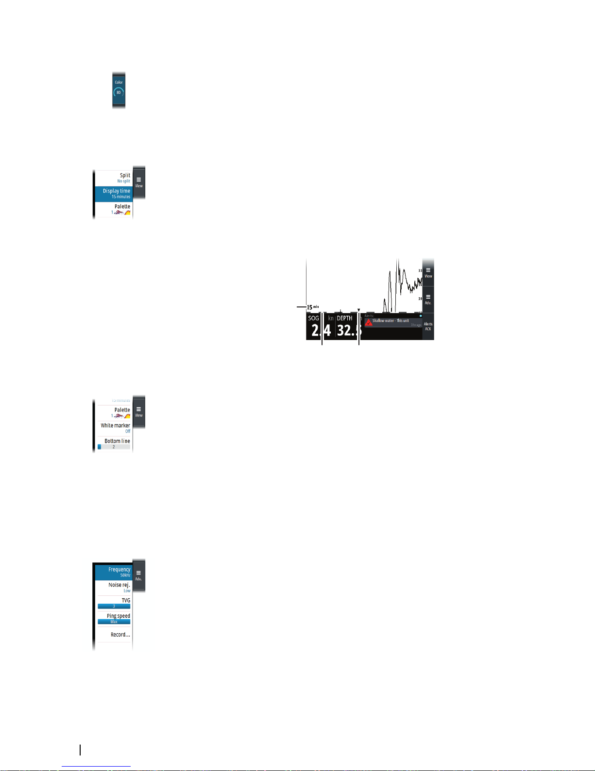
Display time
You can change the length of the depth history shown on the display. This does not affect
already collected data, so the length of depth history shown will gradually change from the
old to the new value when changing display time.
The numeric value (A) in the lower-left corner of the panel always shows the age of the
leftmost column on the screen.
A zebra scale (B) is shown at the bottom of the image, and each stripe equals one minute.
If there is a discontinuity in the depth signal, this is indicated with a triangle (C).
A
B C
16
Optional image items
Palettes
You can select between several display palettes.
White marker
Use this option to change a specific color on the image to white. This effectively highlights
(or hides) the selected color.
Bottom line
The bottom line option makes it easier to distinguish the bottom from other objects. You can
specify the thickness of the line.
Advanced options
Frequency
The unit supports several transducer frequencies. Available frequencies depend on the
transducer model that is configured for use.
Noise rejection
Signal interference from bilge pumps, engine vibration and air bubbles can clutter the
image.
The noise rejection option filters the signal interference and reduces the on-screen clutter.
TVG
Wave action and boat wakes can cause onscreen clutter near the surface. The TVG (Time
Variable Gain) option reduces surface clutter by decreasing the sensitivity of the receiver near
the surface.
Setting up the echosounder image | S3009 Echo Sounder User Manual
Page 17

Ping speed
Ping speed controls the rate the transducer transmits the signal into the water. By default,
the ping speed is set to max. It may be necessary to adjust the ping speed to limit
interference.
Setting up the echosounder image | S3009 Echo Sounder User Manual
17
Page 18

Panel setup
Selecting transducer source
Depth data can be obtained from more than one transducer connected to the system. Refer
to "System examples" on page 26.
Select the transducer to be shown in a panel from the View menu.
Split screen options
Dual
The dual split option allows for viewing signals from two transducers at the same time.
When the function is selected, use the orientation option (A) to select if the panels shall be
arranged on top of each other or side-by-side.
Gain and color icons (B) are displayed on dual panels.
Press the rotary knob to switch focus between the panels. Active panel is indicated with a
border.
Zoom
The split Zoom mode presents a magnified view of the sounder image on the left side of the
panel.
By default, the zoom level is set to 2x, and you can increase this up to 8x.
Change the zoom level by pressing the Zoom softkey and then turning the rotary knob.
Zoom bars (A) are available from the View menu. The bars indicate the range that is
magnified and displayed on the left side.
5
18
Panel setup | S3009 Echo Sounder User Manual
Page 19

Bottom lock
The bottom lock mode is useful when you want to view echoes close to the bottom. In this
mode, the left side of the panel shows an image where the bottom is flattened. The range
scale is changed to measure from the seabed (0) and upwards. The bottom and the zero line
are always shown on the left image, independent of the range scale. The scaling factor for
the image on the left side of the panel is adjusted as described for the Zoom option.
Show or hide the softkey bar
By default, the softkey bar is displayed on the panel.
Select the hide menu option to immediately hide the softkey bar. Pressing any softkey re-
displays the softkey bar.
Auto hide the softkey bar
Selecting the auto hide option will hide the softkey bar after a few seconds of no softkey
activity. Pressing any softkey re-displays the softkey bar.
Edit the content of the Instrument bar
The data types shown in the instrument bar gauges can be changed.
To select a gauge for editing:
• Select the Edit instrument bar in the main menu to enter edit mode, then use the arrow
keys to select the gauge
-
Active gauge is indicated with a border
• Press the Enter key to select preferred data
• Select the finish editing option in the menu to confirm the changes and leave edit mode
Panel setup | S3009 Echo Sounder User Manual
19
Page 20

Advanced options
Recording depth data
You can record depth data. The file can be saved internally in the unit or onto a card inserted
into the unit’s card reader.
When the data is being recorded, a message appears periodically at the bottom of the
screen.
You specify the log details in the log dialog.
Managing files
Select the files option in the Main menu to open the Files dialog.
You can copy, rename, and delete files. You can transfer files from the unit to a memory card
in the card reader and vice-versa using the copy option.
Simulator
The simulation feature lets you see how the unit works without being connected to sensors
or other devices.
Simulator source files
You can select which data files that are used by the simulator. It can be either pre-recorded
data files included in your device, your own recorded log files, or files on a card inserted in
the unit's card reader.
6
20
Advanced options | S3009 Echo Sounder User Manual
Page 21

Data logging
Depth data, alerts history and NMEA 0183 data are automatically saved to internal log files.
The files can be exported using the Files option. Refer to "Exporting the log files" on page 21.
Depth log
Every second the depth data from all shown transducers is stored, along with the ship's
position and time. Data is split in individual files for periods of 12 hours.
Logs from the last 72 hours are stored in the internal memory.
If an SD card is inserted, logs will also be automatically written to the card. There is no age
limit on data stored on the SD card, and data will be recorded until the SD card is full. At this
time, the oldest log file will be deleted.
Alert log
An alert log is stored internally. The log contains time, time source, alert ID, alert text, and
alert action for the most recent 300 alert events.
NMEA 0183 data log
All serial output sentences sent over the NMEA 0183 connection are logged to an internal
file. You can export and review this file for service and fault finding purposes.
The maximum file size is predefined. The system logs as much data as possible within the file
size limitation, and then it starts overwriting the oldest data.
Exporting the log files
The log file can be exported from the Files dialog to a memory card in the card reader.
7
Data logging | S3009 Echo Sounder User Manual
21
Page 22

The alert system
The system will continuously check for danger situations and system faults while running.
Type of alerts
There are 2 alert types in the system:
• Alarms: This is the system's highest priority alert, activated when situation occurs that
might result in collision, or for conditions that critically effect the capability or
performance of the system. An alarm is accompanied by an audible signal, and the alarm
icon flashes until the alarm is acknowledged.
• Cautions: This is information about danger and caution objects that require attention.
Cautions have no audible signal.
Alert notifications
When an alert is triggered, the alert appears in the Alerts panel.
The alerts are displayed in a sorted order. The sort order is first by state (i.e. not
acknowledged before rectified before acknowledged), then severity (i.e. alarm before
caution), then age.
Alarms have different states:
• Active - not acknowledged, not silenced
• Active - acknowledged
• Rectified - not acknowledged
When an alert has been both rectified and acknowledged, it will disappear from the Alerts
panel.
Cautions cannot be acknowledged, and they disappear from the alert list when the condition
is rectified.
The table below shows alert icon and behavior depending on alert state.
Alert type Icon State Indication
Alarm
Active - not
acknowledged
• Flashing symbol
and descriptive
text
• Audible signal
Active acknowledged
• Steady symbol and
descriptive text
• No audible signal
Rectified - not
acknowledged
• Flashing symbol
and descriptive
text
• No audible signal
Caution Active
• Steady symbol and
descriptive text
• No audible signal
Audible alert signal
The audible alert signal is by default turned ON.
You can select to disable the audible signal when service mode is active, but the audible
signal will be reactivated when service mode is deactivated.
8
22
The alert system | S3009 Echo Sounder User Manual
Page 23

The Alerts dialog
The Alerts dialog is activated from the Alert settings or from the main menu.
The Alerts dialog includes a list of active alerts together with a historic listing of the last alert
state changes. Entries are added to the history whenever an alert is raised, acknowledged,
rectified or cleared.
All alerts in the Alerts dialog include a time stamp.
Alphabetic alert list
Alert type abbreviations:
• C: Caution
• A: Alarm
Alert text Description Type
BAM heartbeat lost
No HBT message is received. Only relevant if one or
more NMEA 0183 ports are configured as BAM interface.
C
Depth missing No depth data from selected sensor C
Low voltage Supply voltage <10 V (12V-15%) C
No time source
No time data from NMEA 2000 or NMEA 0183 position
sensor. Only relevant if the time setting is Auto.
C
Shallow water Depth shallower then set limit A
The alert system | S3009 Echo Sounder User Manual
23
Page 24

Mounting
S3009 Control unit
Mounting guidelines
Ú
Note: Where flush mounted, the enclosure should be dry and well ventilated. In small
enclosures, it may be required to fit forced cooling.
Warning: Inadequate ventilation and subsequent overheating of the unit
may cause unreliable operation and reduced service life. Exposing the unit
to conditions that exceed the specifications could invalidate your warranty.
– refer to "Technical specifications" on page 54.
Parts included
ENGLISH
Installati
o
n
Manual
band
g.
com
ENGLISH
Installat
io
n
Ma
n
ual
bandg.com
E
NGLIS
H
Installation Manual
b
andg.c
om
E
NGLIS
H
Inst
allation Manual
b
andg.com
B
A
C
F
G
H
I
E
D
A Control unit
B Bezels
C Transducer cable
D Power cable
E Document package
F NMEA 0183 cable
G U-bracket mounting kit
H Panel mounting kit
I Junction kit
U-bracket mounting
1. Place the bracket in the desired mounting location. Ensure that the chosen location has
enough height to accommodate the unit fitted in the bracket, and allows tilting of the
unit. In addition, adequate space is required on both sides to allow tightening and
loosening of the knobs.
2. Mark the screw locations using the bracket as a template, and drill pilot holes. Use
fasteners suited to the mounting surface material. If the material is too thin for selftappers, reinforce it, or mount the bracket with machine screws and large washers. Use
only 304 or 316 stainless steel fasteners.
3. Screw down the bracket.
9
24
Mounting | S3009 Echo Sounder User Manual
Page 25

4. Mount the unit to the bracket using the knobs. Hand tighten only. The ratchet teeth in the
bracket and display case ensure a positive grip and prevent the unit changing from the
desired angle.
5. Fix the bracket straps.
6x
2
4 - 5
Panel mounting
The screws and gasket used for panel mounting are included in the box.
For mounting instructions, refer to the mounting template.
Transducers
The ideal mounting location for transducers depend on the design of the vessel.
The installation shipyard must ensure sufficient reinforcement and watertightness of the hull,
and must design and manufacture installation hardware that fits the transducer and the
vessel.
For dimensional drawings refer to "Dimensions - TGM60-50-xxL and TGM50-200-xxL transducers" on page
50.
S5100 echosounder module
For S5100 echosounder module mounting information, refer to separate installation
instructions included with the module.
Mounting | S3009 Echo Sounder User Manual
25
Page 26

Wiring
Guidelines
Don't:
• make sharp cable bends
• run cables in a way that allows water to flow down into the connectors
• run the data cables adjacent to radar, transmitter, or large/high current carrying cables or
high frequency signal cables
• run cables so they interfere with mechanical systems
• run cables over sharp edges or burrs
Do this:
• make drip and service loops
• use cable-tie on all cables to keep them secure
• solder/crimp and insulate all wiring connections if extending or shortening the cables.
Extending cables should be done with suitable crimp connectors or solder and heat
shrink. Protect joints from water, humidity and otherwise corrosive environments
• leave enough space for connecting and disconnecting cables
Warning: Before starting the installation, be sure to turn electrical power
off. If power is left on or turned on during the installation, fire, electrical
shock, or other serious injury may occur. Be sure that the voltage of the
power supply is compatible with the unit.
Warning: The positive supply wire (red) should always be connected to
(+) DC with a fuse or a circuit breaker.
System examples
Single transducer system
C
B
A A
D
E
F
D
E
F
B
A S3009 control unit
B TGM50-200-xxL or TGM60-50-xxL transducer
C S5100 sonar module
D NMEA 0183/IEC61162-1
E NMEA 2000/IEC61162-3
F NC isolated alarm circuit
10
26
Wiring | S3009 Echo Sounder User Manual
Page 27

Dual transducer system
C
B B
A
D
E
F
A S3009 control unit
B TGM50-200-xxL or TGM60-50-xxL transducer
C S5100 sonar module
D NMEA 0183/IEC61162-1
E NMEA 2000/IEC61162-3
F NC isolated alarm circuit
Transducer wiring
The transducers are shipped with a 20 meter long cable. An extension cable can be installed
if a total length of more than 20 meters is required between the transducer and the S3009 or
S5100 module.
For dual transducer installations, an S5100 module has to be installed.
E
D
A
B
C
E
G
F
B
C
A S3009 7-pin transducer cable
B Optional extension cable
C Transducer cable (20 meters)
D Junction, 7-pin transducer cable (A) to transducer cable (C) or optional extension
cable (B)
E Junction (optional), extension cable (B) to transducer cable (C)
F S5100 9-pin transducer cable
G Junction, 9-pin transducer cable (F) to transducer cable (C) or optional extension
cable (B)
Wiring | S3009 Echo Sounder User Manual
27
Page 28

Extension cable
An extension cable can be installed if a total length of more than 20 meters is required
between the transducer and the S3009 or S5100 module.
Ú
Note: A 2 x 2,5/2,5 mm² or a 2 x 1,5/1,5 mm² cable shall be used.
S3009 transducer wiring
The S3009 is equipped with a 7-pin transducer connector at the back of the unit.
1 Red
5 Black
6 / 7 Shield
Not used
1 White
2 Black
3 Shield
1 Unk
nown color
2 Unknown color
3 ShieldDepth GND
Depth -
Depth +
1 Unknown color
2 Unk
nown color
3 Shield Depth GND
Depth -
Depth +
Optional extension cable (B)
7-
pin
c
onnector
Transducer
Junction (E)
Junction (D)
(A)
(C)
Ú
Note: For more details, refer to "Extension cable" on page 28 and "Junction details" on page 30.
Echosounder 7-pin connector details
1
2
3
4
5
6
7
Unit socket (female)
1
2
3
4
5
6
7
Cable plug (male)
Pin Purpose
1 Depth +
2 Speed signal
3 Speed volts
4 Temp +
5 Depth -
6 Depth Gnd (shield)
7 Temp - (shield)
E
D
A
B
C
28
Wiring | S3009 Echo Sounder User Manual
Page 29

S5100 transducer wiring
The S5100 is equipped with three 9-pin transducer connectors.
5 Red
4 Black
1 Shield
Not used
1 White
2 Black
3 Shield
1 Unk
nown color
2 Unknown color
3 ShieldDepth GND
Depth -
Depth +
1 Unknown color
2 Unk
nown color
3 Shield Depth GND
Depth -
Depth +
Optional extension cable (B)
Transducer
Junction (E)
Junction (G)
9-pin
connector
(F)
(C)
Ú
Note: For more details, refer to "Extension cable" on page 28 and "Junction details" on page 30.
Echosounder 9-pin connector details
2
1
9
7
5
4
3
6
8
Unit socket (female)
2
1
9
7
5
4
3
6
8
Cable plug (male)
Pin Purpose
1 Drain/Ground
2 Starboard +
3 Starboard -
4 Transducer TX/RX -
5 Transducer TX/RX +
6 Port +
7 Port -
8 Temp
9 Transducer ID
E
G
F
B
C
Wiring | S3009 Echo Sounder User Manual
29
Page 30

Junction details
Junction E - 2 wire to 2 wire junction
Ú
Note: The terminal block supplied with the junction box shall not be used.
Dimensions:
70 mm
20 mm
30 mm
20 mm
Step by step instructions:
• Slide the provided braided shield sleeve over one of
the cables
• Remove the outer insulation of the cable according
to dimensions
• Push back the cable´s braided shield
• Remove insulation from the conductors
• Connect the conductors with crimp joiners using a
professional crimp tool
• Seal the joint with self-vulcanizing tape
• Pull the braided shields over the joint
• Pull the provided braided shield sleeve over the
joint
• Seal the joint with self-vulcanizing tape
• The joint is now ready to be sealed in the junction
box. Refer to "Junction box assembly" on page 32
30
Wiring | S3009 Echo Sounder User Manual
Page 31

Junction D and G - multicore to 2 wire junction
Ú
Note: The terminal block supplied with the junction box shall not be used.
Dimensions:
20 mm
30
mm
60 mm
X mm
Cut the unused wires in the multicore cable in different lengths to avoid short-circuiting
wires.
Step by step instructions:
• Slide the provided braided shield sleeve over one of
the cables
• Remove the outer insulation of the 2-wire cable
• Push back the cable´s braided shield
• Remove insulation from the conductors
• Remove the outer insulation of the multicore cable
• Remove the aluminum foil that surrounds the wires
• Separate the wires to be used from the other wires
• Remove insulation from the conductors to be used
• Connect the conductors to be used with crimp
joiners using a professional crimp tool
• Seal the joints with self-vulcanizing tape
• Separate the shield wires from the other wires in the
multicore cable
• Cut the unused wires in the multicore cable in
different lengths to avoid short-circuiting wires
• Apply self-vulcanizing tape over the cut cables and
the joint
• Pull the braided shield and shield wires over the
joint
• Pull the provided braided shield sleeve over the
joint
• Seal the joint with self-vulcanizing tape
Wiring | S3009 Echo Sounder User Manual
31
Page 32

• The joint is now ready to be sealed in the junction
box. Refer to "Junction box assembly" on page 32
Junction box assembly
Ú
Note: The terminal block supplied with the junction box shall not be used.
• Remove the plastic stoppers
• Insert the spacers if the cable diameter is less than
9.5 mm
• Use an optional junction box (sold separately) if the
cable diameter exceeds 12.0 mm
• Place the cable and joint centered in the junction
box
• Attach the junction box lid
• Secure the junction box lid with the supplied
screws
Power wiring
C
C
A
B
D
32
Wiring | S3009 Echo Sounder User Manual
Page 33

A S3009 control unit
B S5100 Echosounder module
C Power cable
D Power control wire
S3009 power wiring
Power connector details
3
4
1
2
Unit socket (male)
1
2
3
4
Cable plug (female)
Pin Purpose Color
1 DC negative Black
2 External alarm output (N/C isolated contact) Blue
3 External alarm output negative return Yellow
4 +12/24 V DC Red
Power connection
The unit is designed to be powered by a 12 or 24 V DC system.
It is protected against reverse polarity, under voltage, and over voltage (for a limited
duration).
A fuse or circuit breaker should be fitted to the positive supply. For recommended fuse
rating, refer to the technical specification in the "Appendix" on page 47.
A B
C
Key Purpose Color
A +12/24 V DC Red
B DC negative Black
C Fuse or circuit breaker
S5100 echosounder module power wiring
For S5100 echosounder module grounding and power connection, refer to separate wiring
instructions included with the module.
Ú
Note: For transducer connection refer to "Transducer wiring" on page 27. Separate
documentation included with the S5100 echosounder module shall not be used for
transducer wiring.
Wiring | S3009 Echo Sounder User Manual
33
Page 34

Ethernet wiring
Both the S3009 and S5100 are equipped with a 5-pin Ethernet connector and can be
connected with a 5-pin Ethernet cable.
C
A
B
A S3009 control unit
B S5100 echosounder module
C 5-pin Ethernet cable
Ethernet connector details
1
2
3
4
5
Unit socket (female)
2
3
1
4
5
Cable plug (male)
Pin Purpose
1 Transmit positive TX+
2 Transmit negative TX-
3 Receive positive RX+
4 Receive negative RX-
5 Shield
NMEA 0183 wiring
The NMEA 0183 serial port provides input (Listeners) and outputs (Talkers) for the various IEC
61162 interfaced sensors. The port uses the NMEA 0183 (serial balanced) standard, and can
be configured in the software for different baud rates up to 38,400 baud. For configuring of
the ports, refer to "Serial ports" on page 43.
NMEA 0183, IEC61162-1
NMEA 0183
D
evices
34
Wiring | S3009 Echo Sounder User Manual
Page 35

NMEA 0183 connector details
1
2
6
7
8
3
4
5
Unit socket (male)
1
2
6
7
3
4
5
8
Cable plug (female)
Pin Port Purpose
1 Port 2 Listener B (Rx+)
2 Port 2 Listener A (Rx-)
3 Port 2 Talker B (Tx+)
4 Port 2 Talker A (Tx-)
5 Port 1 Talker B (Tx+)
6 Port 1 Talker A (Tx-)
7 Port 1 Listener A (Rx-)
8 Port 1 Listener B (Rx+)
NMEA 0183 cable details
For wire color coding of the supplied NMEA 0183 cable(s) see table below.
Pin Color
1 Brown/White
2 Brown
3 Green/White
4 Green
5 Orange/White
6 Orange
7 Blue/White
8 Blue
Talkers and Listeners
Do not connect multiple devices outputting data (Talkers) on to any serial input (RX) of the
unit. The RS422 protocol is not intended for this type of connection, and data will be
corrupted if more than one device transmits simultaneously. The output (TX) however may
drive multiple receivers (Listeners). The number of receivers is finite, and depends on the
receiving hardware. Typically three devices is possible.
NMEA 2000 wiring
The NMEA 2000 data port allows the receiving and sharing of a multitude of data from
various sources.
Wiring | S3009 Echo Sounder User Manual
35
Page 36

NMEA 2000
NMEA 2000
D
evices
NMEA 2000 connector details
2
1
3
4
5
Unit socket (male)
1
2
5
4
3
Cable plug (female)
Pin Purpose
1 Shield
2 NET-S (+12 V DC)
3 NET-C (DC negative)
4 NET-H
5 NET-L
External alarm wiring
The external alarm is connected through the power connector.
NC Isolated Alarm Circuit
Low
Voltage Alarm
Bridge Alert
System
Power connector details
3
4
1
2
Unit socket (male)
1
2
3
4
Cable plug (female)
Pin Purpose Color
1 DC negative Black
2 External alarm output (N/C isolated contact) Blue
3 External alarm output negative return Yellow
4 +12/24 V DC Red
36
Wiring | S3009 Echo Sounder User Manual
Page 37

External alarm
A
B
C
Key Purpose Color
A External alarm output negative return Yellow
B External alarm output (N/C isolated contact) Blue
C Alert management system
Wiring | S3009 Echo Sounder User Manual
37
Page 38

Software setup
Software setup sequence
1 S5100 software update
To use the S5100 in an IMO compliant system, the S5100 must have a dedicated
software version. The update file is found in the S5100 Updaters folder on the
S3009 unit.
Refer to "Software upgrades" on page 45 and "Managing files" on page 20.
2 Time
Set the time, date and format in the Time settings dialog. If an external time
source is connected to the device, set Time setting to Auto to automatically
update the current time. Refer to "System settings" on page 38.
3 Source selection
Make sure that the proper external data sources have been selected. Refer to
"Network settings" on page 41.
4 Echosounder settings
Configure the transducer(s) from the Echo Installation dialog. Source name, keel
offset and transducer type should be configured for all connected transducers.
Refer to "Echo settings" on page 39.
Accessing the settings dialog
Access control
Some of the parameters in the Settings dialogs are intended for system setup and service
engineers. These parameters are password protected, and they are only available by entering
the un-lock code in the Access control dialog.
The access control password is: QWERTY.
Service mode must be selected to get access to all settings.
Service mode does not time out, but it is deactivated when you close the Settings dialogs.
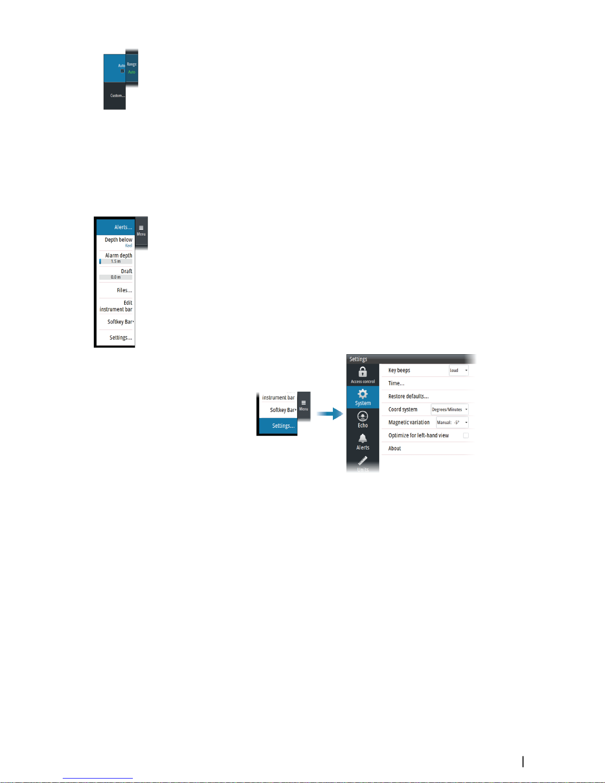
System settings
Use the system settings dialog to set basic settings as described below. Some settings
require a reboot of the system.
11
38
Software setup | S3009 Echo Sounder User Manual
Page 39

Key beeps
Controls the loudness of the beep sound when a key is pressed.
Time
Controls the local time zone offset, and the format of the time and date.
Restore defaults
Restore settings to default factory settings.
Coordinate system
Several coordinate systems can be used to control the format for latitude and longitude
coordinates.
Magnetic variation
Defines how magnetic variation is handled by the system.
• Auto: Receives variation data from a network source
• Manual: Used for manually entering a value for the magnetic variation
Optimize for left-hand view
Select this option to optimize the display for viewing from the left.
About
Displays copyright information, software version, and technical information for this unit.
Echo settings
Network Echosounder
Select to share transducers from this unit with other units connected on the Ethernet
network. In addition, the setting must be selected in order to see other enabled sonar
devices on the network.
When unselected, transducers connected to this unit cannot be shared with other units
connected on the network, nor can it see other sources on the network that have this feature
enabled.
Software setup | S3009 Echo Sounder User Manual
39
Page 40

Internal echosounder
When selected, the internal echosounder is available for selection in the echosounder panel
menu.
When unselected, this option disables the internal echosounder in the unit. It will not be
listed as a echosounder source for any unit on the network. Unselect this option on units
which do not have a transducer connected.
Network echosounder mode
The network echosounder mode setting selects whether only one or multiple echosounder
sources can be selected at the same time.
Ú
Note: Changing the mode requires that all connected sources are restarted.
Restore sonar defaults
Restore echosounder settings to default.
Use depth data from
Select which depth source that shares data on the NMEA 2000 network and on the NMEA
0183 (DPT sentence).
Installation
Source
Select this option to display a list of Echosounder sources available for setup. The settings
you make in the rest of the dialog pertain to the source selected.
Source name
Select this option to set a descriptive name for the selected transducer.
Search depth
Noise may cause the echosounder to search for unrealistic depths. By setting the search
depth manually the system displays echoes received from objects within the set depth
range.
Keel offset
All transducers measure water depth from the transducer to the bottom. As a result, water
depth readings do not account for the distance from the transducer to the lowest point of
the boat (for example; bottom of the keel, rudder or propeller) in the water or from the
transducer to the water surface.
40
Software setup | S3009 Echo Sounder User Manual
Page 41

A
A
A Keel offset
Set the keel offset to the distance from the bottom of the transducer to the lowest point of
the boat in the water (positive value).
Transducer type
Transducer type is used for selecting the transducer model connected to the sonar module.
The transducer selected will determine what frequencies the user can select during
operation.
Units settings
Used for specifying the units of measurement displayed.
Network settings
Use the Network settings dialog to setup networks and connect to network devices.
Info
Displays the Ethernet connection status, the unit's IP and MAC addresses.
Device name
Assigning a name is useful in systems using more than one device of the same type and size.
Data source selection
Ú
Note: If NMEA 0183 is used, complete the NMEA 0183 setup prior to doing source
selection. Refer to "NMEA 0183 setup" on page 43.
Data sources provide live data to the system.
The data may originate from modules internal to the unit, or external modules connected to
the NMEA 2000 or via NMEA 0183 if available on the unit.
Software setup | S3009 Echo Sounder User Manual
41
Page 42

When a device is connected to more than one source providing the same data, the user can
choose the preferred source. Before commencing with source selection make sure all
external devices and the NMEA 2000 backbone are connected and are turned on.
Auto select data sources
The Auto select option looks for all sources connected to the unit. If more than one source is
available for each data type, selection is made from an internal priority list. This option is
suitable for the majority of installations.
Ú
Note: Auto data source selection may already have been selected at first time startup.
However, it should be redone if any new devices have been added to the network since.
Advanced data source selection
The advanced option allows for you to manually select or unselect data sources. Manual
selection is generally only required where there is more than one source for the same data,
and the ‘Auto select’ selected source is not the one desired.
Device list
The Device list shows all NMEA 2000 devices.
Selecting a device in this list will bring up additional details and options for the device.
All devices allow allocation of an instance number in the Configure option. Set unique
instance numbers on any identical devices on the network to allow the unit to distinguish
between them. The Data option shows all data being output by the device. Some devices
will show additional options specific to the device.
Ú
Note: Setting the instance number on a 3rd party product is typically not possible.
Diagnostics
The NMEA 2000 tab on the diagnostics page can provide information useful for identifying
an issue with the network.
Ú
Note: The following information may not always indicate an issue that can be simply
resolved with minor adjustment to network layout or connected devices and their
activity on the network. However, Rx and Tx errors are most likely indicating issues with
the physical network, which may be resolved by correcting termination, reducing
backbone or drop lengths, or reducing the number of network nodes (devices).
Bus state
Indicates whether the bus is powered, but not necessarily connected to any data sources.
However, if bus shows as off, but power is present along with an increasing error count, it is
possible that termination or cable topology is incorrect.
Rx Overflows
The unit received too many messages for its buffer before the application could read them.
Rx Overruns
The unit contained too many messages for its buffer before the driver could read them.
Rx/Tx Errors
These two numbers increase when there are error messages, and decrease when messages
are received successfully. These (unlike the other values) are not a cumulative count. Under
normal operation these should be at 0. Values around 96 upwards indicate a heavily error
prone network. If these numbers go too high for a given device, it will automatically drop off
the bus.
Rx/Tx Messages
Shows actual traffic in and out of device.
42
Software setup | S3009 Echo Sounder User Manual
Page 43

Bus Load
A high value here indicates network is near full capacity. Some devices automatically adjust
rate of transmission, if network traffic is heavy.
Fast Packet Errors
Cumulative counter of any fast packet error. This could be a missed frame, or a frame out of
sequence etc. NMEA 2000 PGNs are made of up to 32 frames. The entire message will be
discarded when a frame is missed.
Ú
Note: Rx and Tx Errors often indicate an issue with the physical network, which may be
resolved by correcting termination, reducing backbone or drop lengths, or reducing the
number of network nodes (devices).
Reset counters
Resets all counters in the NMEA 2000 tab of the Diagnostics dialog to zero. The counters start
recounting immediately.
SimNet Groups
The SimNet Group function is used to control parameter settings, either globally or in groups
of units. The function is used on larger vessels where several SimNet units are connected to
the network. By assigning several units to the same group, a parameter update on one unit
will have the same effect on the rest of the group members.
Damping
If data appears erratic or too sensitive, damping may be applied to make the information
appear more stable. With damping set to off, the data is presented in raw form with no
damping applied.
Calibration
An offset (positive or negative) can be applied to correct inaccuracies in boat speed, sea
temp, air temp, barometric pressure, and depth sourced from NMEA 2000 devices.
NMEA 0183 setup
The NMEA 0183 port must be set to suit the speed of connected devices, and can be
configured to output only the sentences required by listening devices.
Serial ports
Specifies the baud rate for port for the devices connected to the NMEA 0183. The baud rate
should be set to correspond with devices connected to the NMEA 0183 input and output.
Software setup | S3009 Echo Sounder User Manual
43
Page 44

Ports configuration
Each port can be configured to the following Modes:
• Disabled - select this mode if the port is not used (default mode)
• Standard - in this mode the output sentences can be manually configured
• BAM - select to communicate with an external Bridge Alert Management system
conforming to IEC 61924-2
• Legacy alerts - select to communicate with a legacy BAM, using ALR and ACK sentences
44
Software setup | S3009 Echo Sounder User Manual
Page 45

Maintenance
Preventive maintenance
The unit does not contain any field serviceable components. Therefore, the operator is
required to perform only a very limited amount of preventative maintenance.
If a sun cover is available, it is recommended that you always fit it when the unit is not in use.
Cleaning the display unit
A proper cleaning cloth should be used to clean the screen, where possible. Use plenty of
water to dissolve and take away salt remains. Crystalized salt may scratch the coating if using
a damp cloth. Apply minimal pressure to the screen.
Where marks on the screen cannot be removed by the cloth alone, use a 50/50 mixture of
warm water and isopropyl alcohol to clean the screen. Avoid any contact with solvents
(acetone, mineral turpentine, etc.), or ammonia based cleaning products, as they may
damage the anti-glare layer or plastic bezel.
To prevent UV damage to the plastic bezel, it is recommended that the sun cover be fitted
when the unit is not in use for an extended period.
Cleaning the media port door
Clean the media port door regularly to avoid salt crystallization on the surface, causing water
to leak into the card slot.
Checking the keys
Make sure that no keys are stuck in the down position. If one is stuck, wiggle the key to free it
back to normal.
Checking the connectors
The connectors should be checked by visual inspection only.
Push the connector plugs into the connector. If the connector plugs are equipped with a
lock, ensure that it is in the correct position.
Software upgrades
The latest software is available for download from our website: www.navico.com/
commercial.
Start the update by selecting the update file from the Files menu option.
The example shows the sequence when updating the S5100 with the file included in the
S3009 unit.
12
Maintenance | S3009 Echo Sounder User Manual
45
Page 46

Before initiating an update to the unit itself, be sure to back up any potentially valuable user
data.
Backing up your system data
It is recommended to regularly copy your system settings files as part of your back-up
routine. The files can be copied to a card inserted in the card reader. Refer to "Managing files" on
page 20.
46
Maintenance | S3009 Echo Sounder User Manual
Page 47

Appendix
Menu overview
Softkey menus
The system includes a main Menu, a View menu and an Advanced menu as shown below.
The menus are access by pressing the corresponding softkey.
Symbols used:
> access sub menu
... open dialog
Softkey Menu level 1 Menu level 2
Menu Alerts ...
Depth below
Alarm depth
Draft
Files ...
Edit Instrument bar
Softkey bar > Hide
Auto hide
Settings ...
View Source
Split
Display time
Palette
White marker
Bottom line
Zoom bars
Advanced Frequency
Noise rejection
TVG
Ping speed
Record ...
13
Appendix | S3009 Echo Sounder User Manual
47
Page 48

Settings menu
The system includes a Settings menu, accessed from the main menu.
Level 1 Level 2
Access control Service mode
Enter password ...
System Key beeps
Time...
Restore defaults
Coordinate system
Magnetic variation
Optimize for left hand view
About
Echo Network sonar
Internal echosounder
Network mode
Restore sonar defaults ...
User depth data from
Installation ...
Alerts Siren enabled
Alerts ...
Units Distance
Distance small
Wind speed
Speed
Depth
Altitude
Heading
Temperature
Volume
Economy
Pressure
Baro pressure
Network Info
Device name
Sources ...
Device list
Diagnostics
Simnet groups ...
Damping ...
Calibration >
NMEA 0183 >
Simulator Simulate
Files ...
48
Appendix | S3009 Echo Sounder User Manual
Page 49

Dimensional drawings
Dimensions - S3009 Control unit
247 mm (9.72”)
224 mm (8.81”)
219 mm (8.62”)
80 mm
(3.14”)
67 mm
(2.63”)
100 mm (3.93”)
280 mm (11.02”)
260 mm (10.23”)
Appendix | S3009 Echo Sounder User Manual
49
Page 50

Dimensions - TGM60-50-xxL and TGM50-200-xxL transducers
ø69.5 mm
(2.74”)
ø88.5 mm
(3.48”)
40 mm
(1.58”)
R 8 mm
(0.31”)
R 4 mm
(0.16”)
20 mm
(0.79”)
60 mm
(2.36”)
60 mm
(2.36”)
20 m
(65.62’)
55 mm
(2.17”)
5 mm (0.2”)
ø22 mm (0.87”)
ø25 mm (0.98”)
3 mm (0.12”)
15 mm
(0.59”)
50
Appendix | S3009 Echo Sounder User Manual
Page 51

Supported data
Ú
Note: NMEA 0183 and NMEA 2000 data output requires the connection of relevant
sensors.
NMEA 0183 sentences
Sentence Description In Out
DBT Depth Below Transducer x x
DPT Depth x x
DSC Digital Selective Calling Information x
DSE Expanded Digital Selective Calling x
DTM Datum reference x
GGA Global positioning system (GPS) fix data x x
GLC Geographic Position - Loran C x
GLL Geographic position- latitude and longitude x x
GNS GNSS fix data x
GSA GNSS DOP and Active Satellites x x
GSV GNSS Satellites in view x x
HDG Heading - Deviation & Variation x x
HDM Heading - Magnetic x
HDT Heading - True x
MOB Man Over Board x
MTW Water Temperature x x
MWD Wind Direction and Speed x x
MWV Wind Speed and Angle x x
OSD Own ship data x
RMC Recommended Minimum Specific GNSS
Data
x x
RSD Radar system data x
RTE Routes x
THS True heading and status x
TLB Target label x
TLL Target Latitude & Longitude x
TTD Tracked target data x
TTM Tracked target message x
VBW Dual ground/water speed x
VDM AIS VHF data-link message x
VDO AIS VHF data-link own vessel report x
VHW Water speed and heading x x
VLW Distance traveled through water x x
VTG Course over ground and ground speed x x
WPL Waypoint Location x
XDR Transducer measurements x x
ZDA Time and date x x
Appendix | S3009 Echo Sounder User Manual
51
Page 52

NMEA 2000 compliant PGN List
NMEA 2000 PGN (receive)
59392 ISO Acknowledgement
59904 ISO Request
60928 ISO Address Claim
126208 ISO Command Group Function
126992 System Time
126996 Product Info
127237 Heading/Track Control
127245 Rudder
127250 Vessel Heading
127251 Rate of Turn
127257 Attitude
127258 Magnetic Variation
127488 Engine Parameters, Rapid Update
127489 Engine Parameters, Dynamic
127493 Transmission Parameters, Dynamic
127503 AC input status
127504 AC Output Status
127505 Fluid Level
127506 DC Detailed Status
127507 Charger Status
127508 Battery Status
127509 Inverter Status
128259 Speed, Water referenced
128267 Water Depth
128275 Distance Log
129025 Position, Rapid Update
129026 COG & SOG, Rapid Update
129029 GNSS Position Data
129033 Time & Date
129038 AIS Class A Position Report
129039 AIS Class B Position Report
129040 AIS Class B Extended Position Report
129041 AIS aids to Navigation
129283 Cross Track Error
129284 Navigation Data
129539 GNSS DOPs
129540 AIS Class B Extended Position Report
129794 AIS aids to Navigation
129801 Cross Track Error
129283 Cross Track Error
129284 Navigation Data
129539 GNSS DOPs
52
Appendix | S3009 Echo Sounder User Manual
Page 53

129540 GNSS Sats in View
129793 AIS UTC & Date Report
129794 AIS Class A Static and Voyage Related Data
129798 AIS SAR Aircraft Position Report
129801 AIS Addressed Safety Related Message
129802 AIS Safety Related Broadcast Message
129808 DSC Call Information
129809 AIS Class B “CS” Static Data Report, Part A
129810 AIS Class B “CS” Static Data Report, Part B
130074 Route and WP Service - WP List - WP Name & Position
130306 Wind Data
130310 Environmental Parameters
130311 Environmental Parameters
130312 Temperature
130313 Humidity
130314 Actual Pressure
130576 Small Craft Status
130577 Direction Data
130578 Vessel Speed Components
NMEA 2000 PGN (transmit)
126208 ISO Command Group Function
126992 System Time
126996 Product Info
127237 Heading/Track Control
127250 Vessel Heading
127258 Magnetic Variation
128259 Speed, Water referenced
128267 Water Depth
128275 Distance Log
129025 Position, Rapid Update
129026 COG & SOG, Rapid Update
129029 GNSS Position Data
129283 Cross Track Error
129284 Navigation Data
129285 Route/Waypoint Data
129539 GNSS DOPs
129540 GNSS Sats in View
130074 Route and WP Service - WP List - WP Name & Position
130306 Wind Data
130310 Environmental Parameters
130311 Environmental Parameters
130312 Temperature
130577 Direction Data
Appendix | S3009 Echo Sounder User Manual
53
Page 54

Technical specifications
Ú
Note: The most up-to-date specifications list is available at: www.navico.com/
commercial
Technical specification - S3009 Control unit
Connectivity
Sonar 1 (1 kW RMS)
NMEA 2000 1 (NMEA 2000/IEC 61162-3)
NMEA 0183 2 (NMEA 0183/IEC 61162-1)
Ethernet 1
NMEA 0183 Sentences supported See"NMEA 0183 sentences" on page 51
NMEA 2000 PGNs See "NMEA 2000 compliant PGN List" on page 52
Display
Type 9-inch diagonal, 480 x 800 pixel LCD
Backlighting LED backlit, day/night brightness with 10
increments
Screen brightness
≥ 1200 cd/m
2
Viewing angles 160° horizontal, 110° vertical
Electrical
Supply voltage 10.8 - 31.2 V DC
Power consumption - Max 12 W
Power consumption - Typical 11 W
Recommended fuse rating 3 A
Environmental
Operating temperature range -15°C (5°F) to +55°C (131°F)
Storage temperature -25°C (-13°F) to +70°C (158°F)
Waterproof rating IPx7
Humidity Up to 95% at + 40°C (104°F)
Shock and vibration According to IEC60945 ed 4.0 and RMS rules
(2-020202-040-E Vol 2 Environmental Test of
Equipment)
Physical
Dimensions See "Dimensions - S3009 Control unit" on page 49
Weight 1.95 kg (4.3 lbs)
Compass Safe Distance 0.4 m (1.31 feet)
Mounting type Panel or bracket mount
Card reader 1 (SD card)
54
Appendix | S3009 Echo Sounder User Manual
Page 55

Technical specifications - TGM60-50-xxL transducer
Physical
Dimensions See "Dimensions - TGM60-50-xxL and TGM50-200-xxL
transducers" on page 50
Weight 4.48 kg (9.88 lbs)
Number of wires 2 x 2,5/2,5 mm
Transducer
Output Depth
Frequency 50 kHz
Beam width 44°
Max depth 1 500 m (4 921 ft)
Speed 30 knots (35 mph)
Technical specifications - TGM50-200-xxL transducer
Physical
Dimensions See "Dimensions - TGM60-50-xxL and TGM50-200-xxL
transducers" on page 50
Weight 2.09 kg (4.60 lbs)
Number of wires 2 x 2,5/2,5 mm
Transducer
Output Depth
Frequency 200 kHz
Beam width 11°
Max depth 400 m (1 312 ft)
Speed 30 knots (35 mph)
Appendix | S3009 Echo Sounder User Manual
55
Page 56

*988-12043-001*
www.navico.com/commercial
 Loading...