

Page 1

ENGLISH
S2009-S2016 Fish Finder
User Manual
www.navico-commercial.com
Page 2

Page 3

Preface
Disclaimer
As Navico is continuously improving this product, we retain the right to make changes to the
product at any time which may not be reflected in this version of the manual. Please contact
your nearest distributor if you require any further assistance.
It is the owner’s sole responsibility to install and use the equipment in a manner that will not
cause accidents, personal injury or property damage. The user of this product is solely
responsible for observing maritime safety practices.
NAVICO HOLDING AS AND ITS SUBSIDIARIES, BRANCHES AND AFFILIATES DISCLAIM ALL
LIABILITY FOR ANY USE OF THIS PRODUCT IN A WAY THAT MAY CAUSE ACCIDENTS, DAMAGE
OR THAT MAY VIOLATE THE LAW.
This manual represents the product as at the time of printing. Navico Holding AS and its
subsidiaries, branches and affiliates reserve the right to make changes to specifications
without notice.
Governing Language
This statement, any instruction manuals, user guides and other information relating to the
product (Documentation) may be translated to, or has been translated from, another
language (Translation). In the event of any conflict between any Translation of the
Documentation, the English language version of the Documentation will be the official
version of the Documentation.
Copyright
Copyright © 2016 Navico Holding AS.
Warranty
The warranty card is supplied as a separate document at: www.navico-commercial.com
Regulatory statements
This equipment is intended for use in international waters as well as coastal sea areas
administrated by member states pursuant to international conventions. This equipment
complies with:
This equipment complies with:
• CE under EMC directive 2014/30/EU
• The requirements of level 2 devices of the Radio communications (Electromagnetic
Compatibility) standard 2008
The relevant Declaration of conformity is available on the following website: navicocommercial.com/.
About this manual
This manual is a reference guide for operating and the software setup for the S2009 and
S2016 Fish finder systems.
Separate installation instructions for transducers are included with the transducer package.
The manual will continuously be updated to match new software releases. The latest
available manual version can be downloaded from the website:
www.navico-commercial.com.
Viewing the manual on the screen
The PDF viewer included in the unit makes it possible to read the manuals and other PDF
files on the screen. The manuals can be read from a card inserted in the card reader or copied
to the unit’s internal memory.
The PDF file is opened from the File manager, refer to "Files" on page 22.
Manuals can be downloaded at: navico-commercial.com/
Use the keys to maneuver in the PDF file as described below:
Preface | S2009-2016 Fish Finder User Manual
3
Page 4

• Scroll pages
Use the rotary knob.
• Zoom in/out
Use the + and - keys.
• Maneuver on a page that is larger than the display area
Use the arrow keys.
• Exit the PDF viewer
Use the Exit key.
Safety precautions
The accuracy of the depth displayed can be affected by many factors, including the type and
location of the transducer and water conditions.
The choice, location, and installation of transducers and other components of the system are
critical to the performance of the system as intended. If in doubt, consult your Simrad dealer.
To reduce the risk of misusing or misinterpreting this instrument, you must read and
understand all aspects of the Installation and Operation manuals. We also recommend that
you practice all operations using the built-in simulator before using this instrument on the
water.
Trademarks
Lowrance® and Navico® are registered trademarks of Navico.
Simrad® is used by license from Kongsberg.
NMEA® and NMEA 2000® are registered trademarks of the National Marine Electronics
Association.
SimNet® is a registered trademark of Navico.
SD™ and microSD™ are trademarks or registered trademarks of SD-3C, LLC in the United
States, other countries or both.
HDMI® and HDMI™, the HDMI Logo, and High-Definition Multimedia Interface are trademarks
or registered trademarks of HDMI Licensing LLC in the United States and other countries.
4
Preface | S2009-2016 Fish Finder User Manual
Page 5

Contents
7 The user interface
7
Front panel and keys
8 The main panel
8 Using the cursor on the image
9 Softkeys
10 Slide bars
10 The menu system
12 Basic operation
12 System Controls dialog
12 Turning the system on and off
12 Display illumination
12 Setting the appearance of the Instrument bar
13 Pausing the image
13 Screen capture
13 Show or hide the softkey bar
14 Setting up the image
14 The range
14 Zooming the image
15 Frequency
15 Gain
15 Color
16 View options
17 Split screen options
17 Palettes
18 White marker
18 Temperature graph
18 Bottom line
18 A-Scope
18 Zoom bars
19 Alerts
19 Acknowledging an alert message
20 Advanced options
20 Noise rejection
20 TVG
20 Scroll speed
20 Ping speed
20 Recording log data
22 Files
22 Managing files
22 Exporting the log file
23 Simulator
23 Turning the simulator on/off
23 Simulator source files
24 Installation
24 Mounting location
26 U-bracket mounting
27 Panel mounting
28 Wiring
Contents | S2009-2016 Fish Finder User Manual
5
Page 6

37 Software Setup
37
System settings
38 Echo settings
40 Alerts settings
40 Units settings
40 Network settings
46 Maintenance
46 Preventive maintenance
46 Cleaning the display unit
46 Cleaning the media port door
46 Checking the keys
46 Checking the connectors
46 NMEA Data logging
47 Software upgrades
47 Backing up your system data
48 Technical specifications
48 Display
48 Overview
48 Technical/Environmental
48 Electrical
48 Connectors
49 Card reader
50 Dimensional drawings
50 S2009
50 S2016
6
Contents | S2009-2016 Fish Finder User Manual
Page 7
The user interface
Front panel and keys
Ú
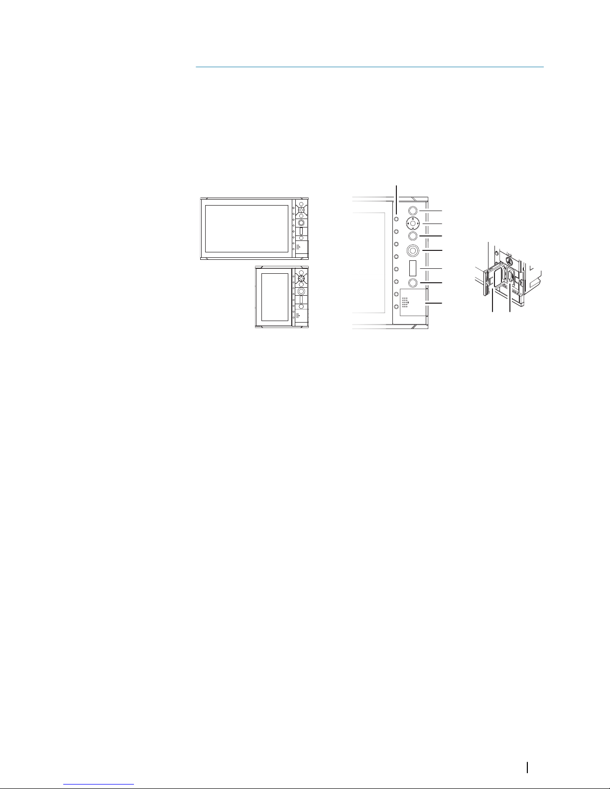
Note: The S2009 Fish finder unit has a 9" display in portrait orientation. The S2016 Fish
finder unit has a 16" display in landscape orientation. The keypad and card reader on
portrait and landscape units are the same. The diagrams and screenshots in this manual
are taken from the S2016.
1
2
3
4
5
6
7
8
8 9
1 Softkeys
Press a key once to access options for the corresponding function.
2 Enter key
Press to select an option or to save settings.
3 Arrow keys
Press to activate the cursor and to move the cursor on the image.
Menu operation: press to navigate through menu items and to adjust a value.
4 Exit key
Press to return to previous menu level or to exit a dialog.
5 Rotary knob
Rotate to scroll through menu items and to adjust values. Press to select or save
settings.
6 Range keys
Press the + or the - key to increase or decrease the range.
7 Power key
Press once to turn ON the unit.
Press and hold to turn OFF the unit.
Short press when the unit is ON opens the System Controls dialog.
8 Card reader door
9 SD card reader
1
The user interface | S2009-2016 Fish Finder User Manual
7
Page 8
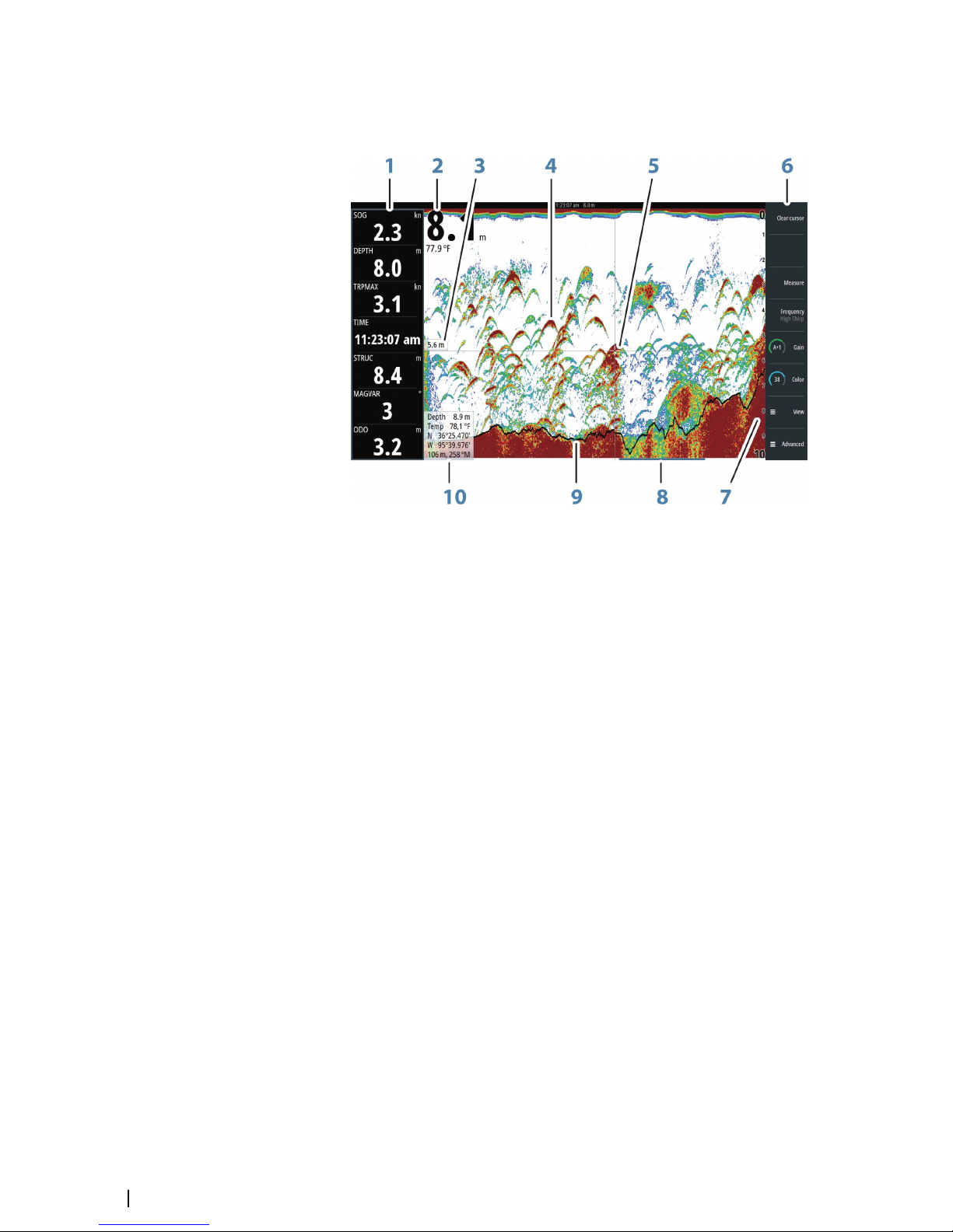
The main panel
The main panel is divided into predefined areas:
1 Instrument bar
2 Depth
3 Depth at cursor position
4 Fish arch
5 Cursor
6 Softkey bar
7 Range
8 History bar
9 Bottom line
10 Cursor information panel
Using the cursor on the image
The cursor can be used to measure the distance between two points, to mark a position, and
to navigate the history view.
By default, the cursor is not shown on the image.
When you position the cursor on the image; the screen pauses, the depth at the cursor
position is shown, and the information window and the history bar are activated.
You activate the cursor by pressing any arrow key. Use the arrow keys to maneuver the cursor
on the image.
To remove the cursor and cursor elements from the panel, press the Clear cursor softkey or
the Exit key.
Measuring distance
The cursor can be used to measure the distance between the position of two observations
on the image.
1. Position the cursor on the point from where you want to measure the distance
2. Start the measuring function by pressing the measure softkey
3. Position the cursor on the second measuring point
8
The user interface | S2009-2016 Fish Finder User Manual
Page 9

- A line is drawn between the measuring points, and the distance is listed in the Cursor
Information panel
4. Continue selecting new measuring points if required
Press the Finished Measurement softkey to exit the measurement feature. The Clear
cursor softkey removes the cursor from the image.
Viewing history
Whenever the cursor is shown on the image, the history bar is shown at the bottom of the
image. The history bar shows the image you are currently viewing in relation to the total
image history stored.
If the scroll bar is on the far right side, it indicates that you are viewing the latest soundings. If
you position the cursor to the left side of the screen, the history bar starts scrolling towards
the left, and the automatic scrolling as new soundings are received is turned off.
You can view echosounder history by panning the image.
To resume normal scrolling, press the Clear cursor softkey or the X key.
Saving waypoints
You can save a waypoint at a selected location by positioning the cursor on the panel, and
then pressing the New waypoint softkey.
Pressing the New waypoint softkey creates a temporary waypoint on the image and sends
it over NMEA 2000 so that the waypoint can be created on an MFD. In order to do this, the
“Send waypoint on NMEA2000” setting must be enabled. Refer to "NMEA 2000" on page 44.
Softkeys
The softkeys are always accessible. By default, the softkey bar is displayed on the panel. You
can hide the softkey bar so that more of the image is displayed. Refer to "Show or hide the softkey
bar" on page 13. When a softkey is pressed, the function for the selected softkey becomes
available.
The arrow keys, the rotary knob and the Enter key have different functions depending on
which softkey is selected.
More details about the softkey functionality are available in the separate section describing
the functions later in this manual.
Softkey pop-ups
If you press the Range, Frequency or Gain softkey twice, their corresponding pop-up is
displayed.
If a pop-up has more than one option, you select the options by using the arrow keys.
You remove the pop-up and revert to the softkey's main function by re-pressing the softkey
or by pressing the Exit key.
The user interface | S2009-2016 Fish Finder User Manual
9
Page 10
Slide bars
Some options display a slide bar.
Press the Enter key, the right arrow key or the rotary knob to activate the slide bar.
When active the slide bar changes from blue to orange and you can adjust the value. Turn
the rotary knob or press the up/down arrow keys to move the slide bar up or down to adjust
the value.
Press the Exit key, the left arrow key or the rotary knob to de-activate the slide bar.
The menu system
The Menu, View and Advanced softkeys display menus. Depending on the menu item,
selecting an item can display sub menus, select options or open dialogs.
A Settings dialog will remain open until it is manually closed.
Main menu and sub menus
You access the Main menu by pressing the Menu softkey.
• Use the up and down arrow keys or turn the rotary knob to move up and down in a menu
• Press the Enter key, the right arrow key or the rotary knob to access a sub menu, to toggle
options and to confirm a selection
• Press the Exit key or the left arrow key to return to previous menu level and then exit the
menu system
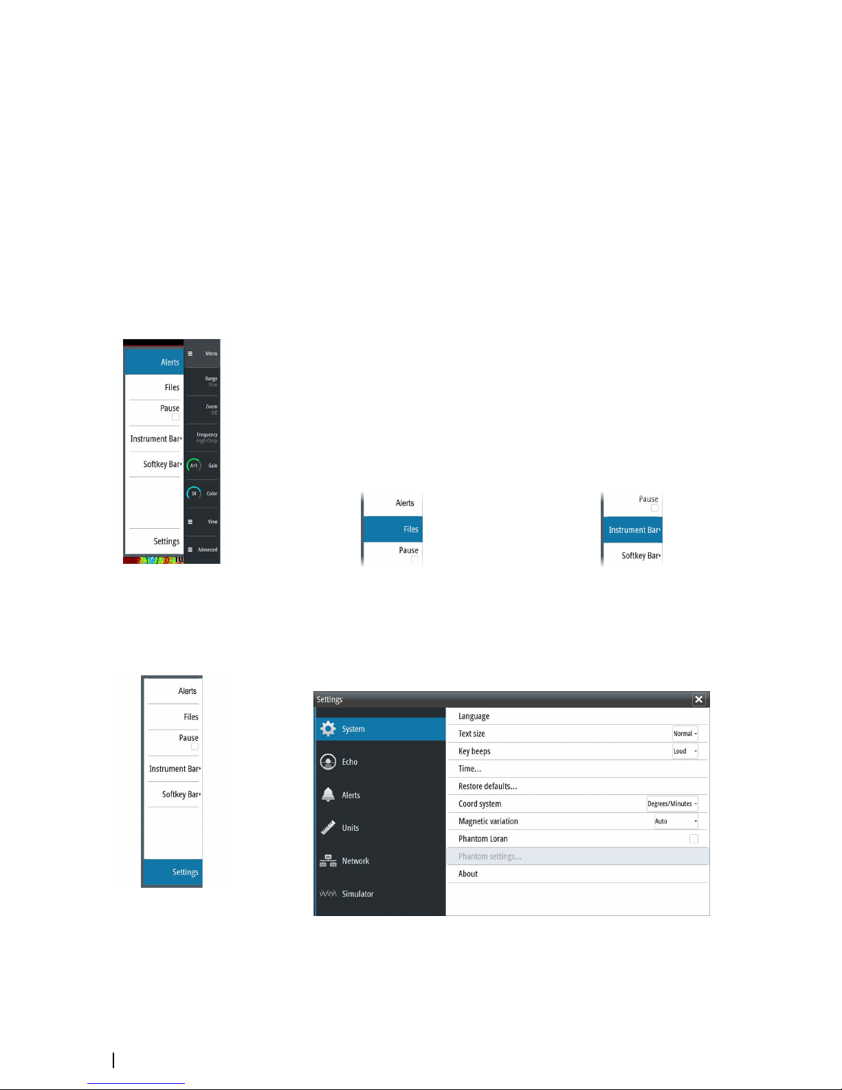
A selected menu item is indicated with a blue background. If a sub-menu is available this is
indicated with a right arrow after the text.
Selected menu item Sub-menu indication
Settings dialogs
The various Settings dialogs provide access to system settings.
You access the Settings dialogs from the Main menu and from the System Controls dialog.
• Use the up and down arrow keys or turn the rotary knob to move up and down in a
Settings dialog
• Press the Enter key, the right arrow key or the rotary knob to access the Settings details
and to confirm a selection
• Press the Exit key to close a dialog
10
The user interface | S2009-2016 Fish Finder User Manual
Page 11
There is no time-out for the Settings dialogs. A dialog remains open until it is manually
closed.
For more information about the Settings dialogs, refer to "Software Setup" on page 37.
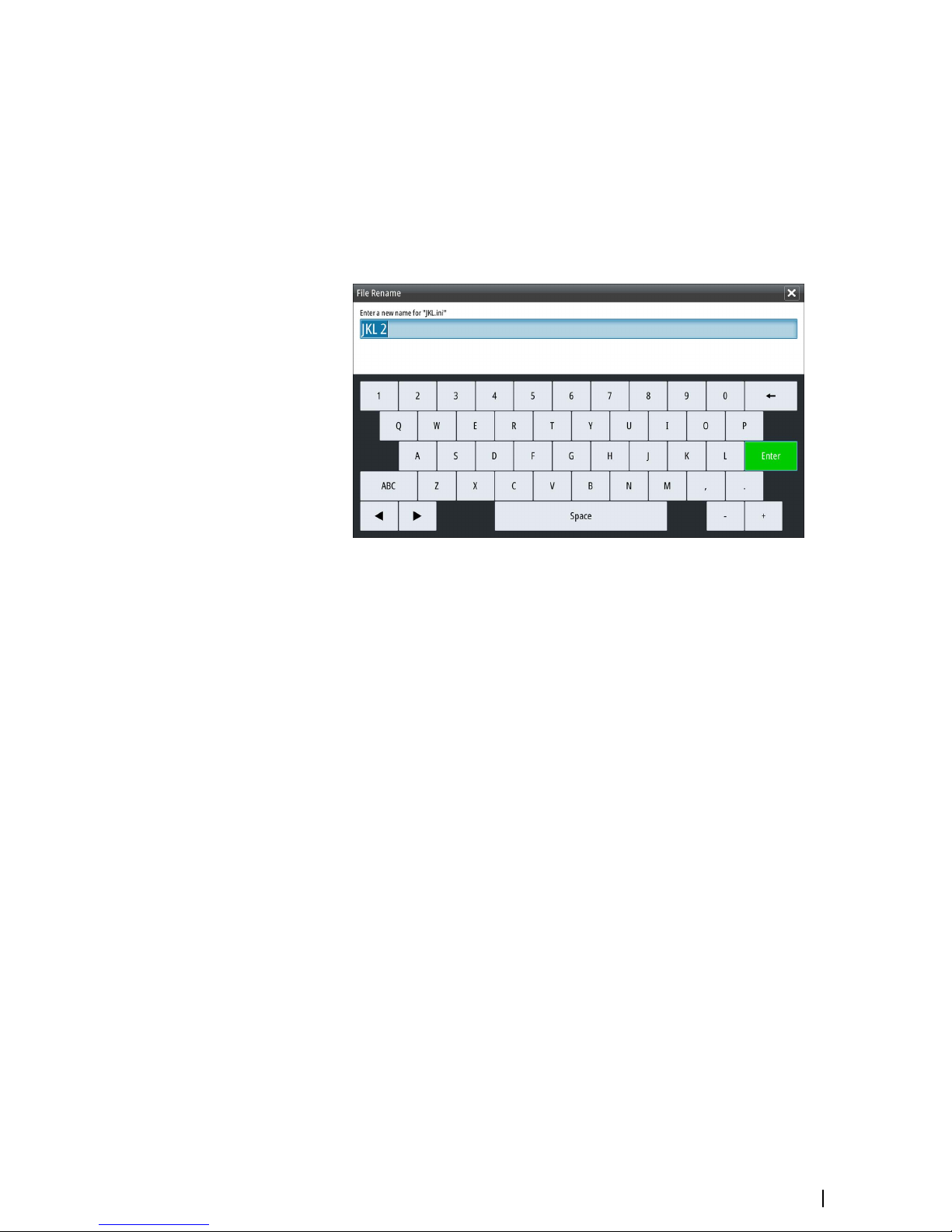
On-screen keyboard
A numeric or alphanumeric virtual keyboard is displayed when required to enter user
information in dialogs.
• Select a virtual key by using the arrow keys followed by the Enter key to confirm the
selection
• Complete the entry and close the dialog by selecting the Enter virtual key
You remove the virtual keyboard without entering information by pressing the Exit key.
The user interface | S2009-2016 Fish Finder User Manual
11
Page 12
Basic operation
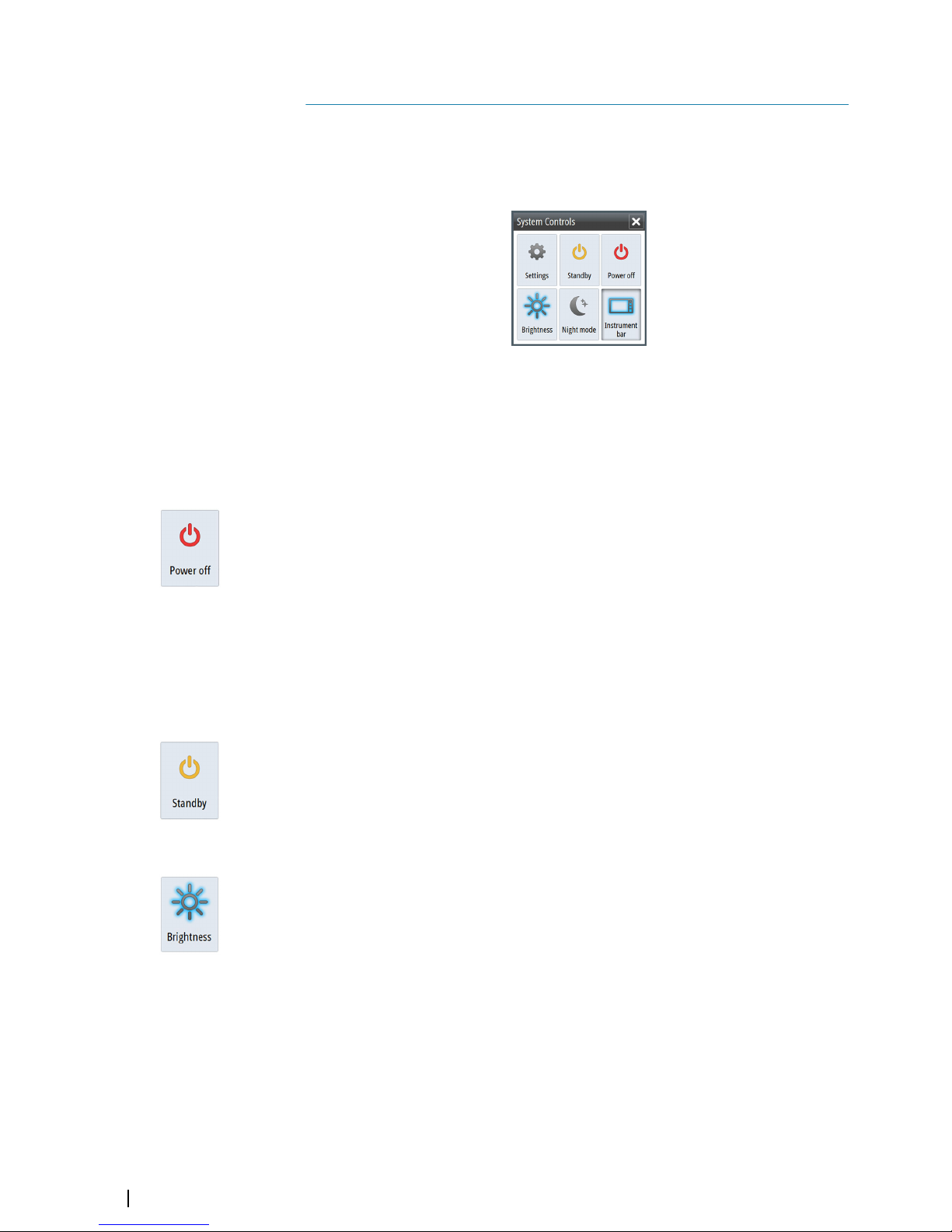
System Controls dialog
The System Controls dialog provides quick access to basic system settings. You display the
dialog by making a short press on the Power key.
Activating functions
Select the icon of the function you want to set or toggle on or off. For those functions that
toggle on and off, a highlighted icon indicates the function is activated, as shown in the
Instrument bar icon above.
Turning the system on and off
You turn the system on and off by pressing and holding the Power key. You can also turn
the unit off from the System Controls dialog.
If the Power key is released before the shut-down is completed, the power off process is
cancelled.
First time startup
When the unit is started for the first time, or after a factory default, the unit displays a setup
wizard. Respond to the setup wizard prompts to select some fundamental setup options.
You can perform further setup using the system settings option and later change settings
made with the setup wizard. Refer to "Software Setup" on page 37.
Standby mode
In Standby mode, the Sonar and the backlight for screen and keys are turned off to save
power. The system continues to run in the background.
You select Standby mode from the System Controls dialog.
Display illumination
Brightness
The display backlighting can be adjusted at any time from the System Controls dialog.
Night mode
The night mode option optimizes the color palette and backlight for low light conditions.
Setting the appearance of the Instrument bar
By default, the Instrument bar is shown on the panel. You can turn the Instrument bar off.
Data sources connected to the system can be viewed in the Instrument bar.
2
12
Basic operation | S2009-2016 Fish Finder User Manual
Page 13
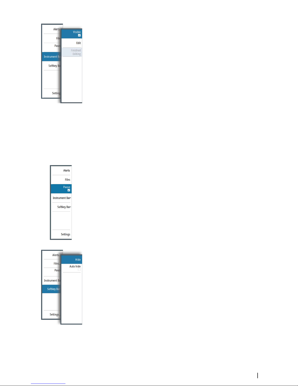
You can specify the information displayed in the instrument bars. Use the Instrument bar
sub-menu to set the appearance of the Instrument bar.
Turning the Instrument bar on/off
1. Activate the System controls dialog
2. Deactivate/activate the instrument bar icon to toggle the bar on and off.
You can also turn the instrument bar on/off from the instrument bar menu option.
Edit the content of the Instrument bar
1. Press the Menu softkey, activate the instrument bar menu option and press the Enter
key.
2. Activate the edit option, and press the Enter key. The top instrument gauge is
highlighted.
3. Press the up/down arrow keys or turn the rotary knob to activate the instrument gauge
you want to change.
4. Press the Enter key or the rotary knob to open the Choose data dialog.
5. Press the up/down arrow keys or turn the rotary knob to activate a category, and then
press the Enter key to expand it.
6. Press the up/down arrow keys or turn the rotary knob to activate a gauge, and then press
the Enter key to select it.
7. Press the up/down arrow keys or turn the rotary knob to select the finished editing menu
option and then press the Enter key to save your changes.
Pausing the image
You can pause the image, allowing you to examine it.
Toggle on/off pause using the pause option in the main menu.
The pause function stops the Echosounder from pinging the transducer. The system is not
collecting Echosounder data when paused in this manner.
Screen capture
Simultaneously press the Enter and Power keys to take a screen capture. Screen captures
are saved to internal memory.
To manage screen capture files, refer to "Managing files" on page 22.
Show or hide the softkey bar
By default, the softkey bar is displayed on the panel. Hiding the softkey bar allows you to
show more of the image.
Select the hide menu option to immediately hide the softkey bar. Pressing any softkey redisplays the softkey bar.
Auto hide the softkey bar
Selecting the auto hide option will hide the softkey bar after a few seconds of no softkey
activity. Pressing any softkey re-displays the softkey bar.
Basic operation | S2009-2016 Fish Finder User Manual
13
Page 14
Setting up the image
You can improve the image by adjusting the range, gain, color, and by filtering out noise.
Some functions include both a manual and an automatic mode. It is recommended to use
the manual mode only if the automatic tuning fails.
The image is controlled by dedicated softkeys as described in the next sections.
When the cursor is active, some options on the menu are replaced with cursor mode
features. Press the Clear cursor softkey or press the Exit key to return to the non-cursor
related softkey options.
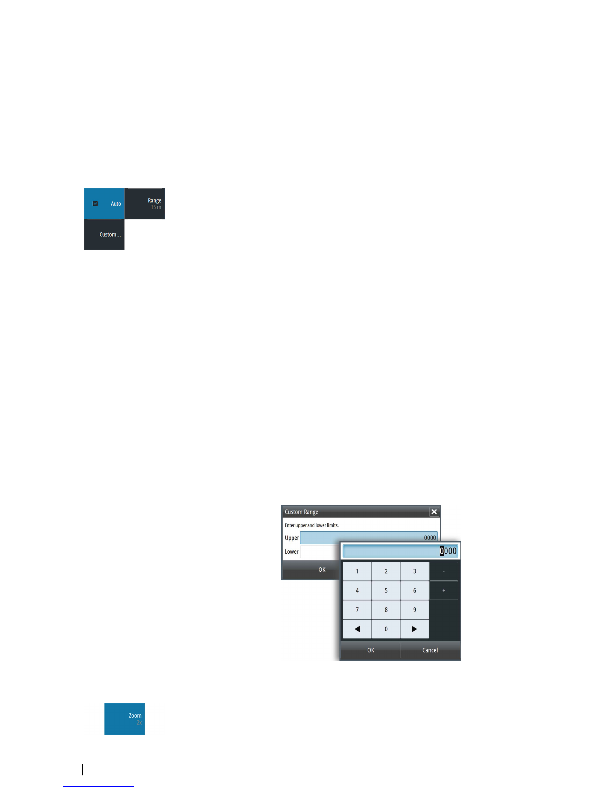
The range
The range setting determines the water depth that is visible on the screen.
Press the Range softkey twice to display the range pop-up.
Preset range levels
Allows for the selection of a specific depth range that is not tied to the depth of the water.
To select a preset range level, press the Range softkey and then turn the rotary knob to
adjust the range to a preset level or use the +/- keys.
Auto range
By default, the range is set to Auto. In auto range, the system automatically displays the
whole range from the water surface to the bottom. Auto is the preferred setting for fish
finding.
Expand the Range pop-up and select Auto gain or press-and-hold the Range softkey to
toggle Auto gain on/off.
Custom range
This option allows you to manually set both upper and lower range limits.
Ú
Note: Setting a custom range puts the system in manual mode. If the bottom is well
beyond the lower range set, you may lose digital depth.
When selected, the Custom Range dialog is displayed where you set the upper and lower
range limits.
Selecting the Upper or Lower fields displays the keypad. Use the up/down arrow keys to
move around the keypad and press the Enter key to select values. Select the OK button to
set the values selected.
Zooming the image
You can zoom the image by:
• Pressing the Zoom softkey and turning the rotary knob
Zoom level is shown on the upper left side of the image.
3
14
Setting up the image | S2009-2016 Fish Finder User Manual
Page 15
When zooming in, the sea floor is kept near the bottom of the screen, irrespective of whether
it is in auto-range or manual range.
If the range is set considerably less than the actual depth, the unit is not able to find the
bottom when zooming.
You can also zoom the image as a split screen and display zoom bars. Refer to split screen
"Zoom" on page 17.
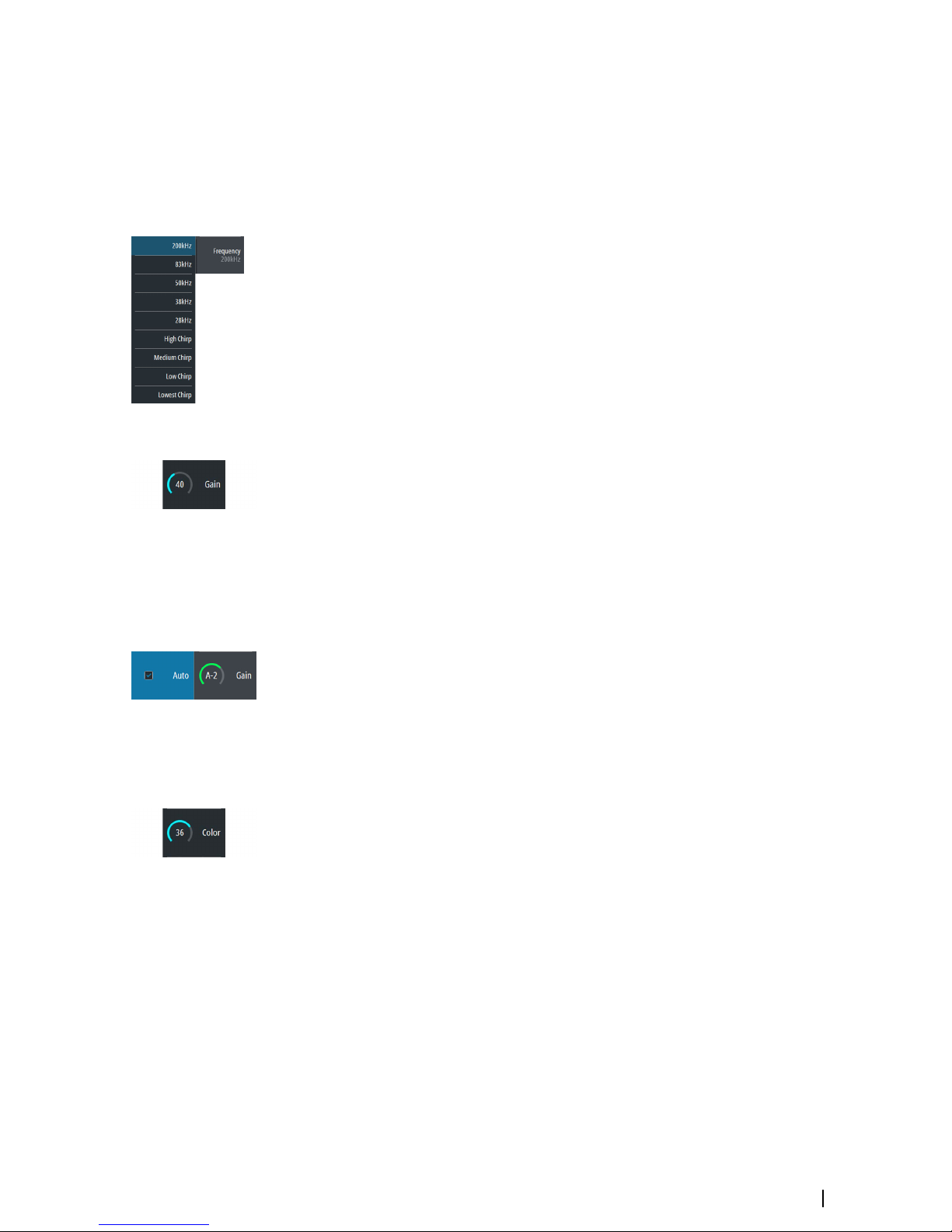
Frequency
The unit supports several transducer frequencies. Available frequencies depend on the
transducer model that is connected.
Frequency is the ‘tone’ the transducer transmits. Transducers are designed to operate on
different frequencies as the various frequencies have different qualities.
To set the frequency, you have two options:
• Press the Frequency softkey once to activate it and then turn the rotary knob to activate
and select a frequency.
• Press the Frequency softkey twice to display the pop-up. Turn the rotary knob to activate
a frequency in the pop-up and then press Enter or the rotary knob to select it.
Gain
The gain controls the sensitivity. The more you increase the gain, the more details are shown
on the image. However, a higher gain setting may introduce more background clutter on the
image. If the gain is set too low, weak echoes might not be displayed.
To set the Gain, press the Gain softkey once and turn the rotary knob to adjust the gain
value.
Auto gain
The Auto gain option keeps the sensitivity at a level that works well under most conditions.
With the gain in auto mode, you can set a positive or negative offset that gets applied to the
auto gain.
To set the Gain to auto, press the Gain softkey twice to display the pop-up. Turn the rotary
knob to activate the Auto pop-up and press the Enter key or rotary knob to select it. A
check-mark is displayed in the check-box when it is selected. Or press-and-hold the Gain
softkey to toggle Auto gain on/off.
To set a positive or negative offset to auto gain with auto selected, turn the rotary knob to
adjust the auto value.
Color
Strong and weak signals have different colors to indicate the different signal strengths. The
colors used depend on which palette you select. The more you increase the Color setting,
the more echoes are displayed in the color at the strong return end of the scale.
To set the Color, press the Color softkey once and turn the rotary knob to adjust the value.
Setting up the image | S2009-2016 Fish Finder User Manual
15
Page 16
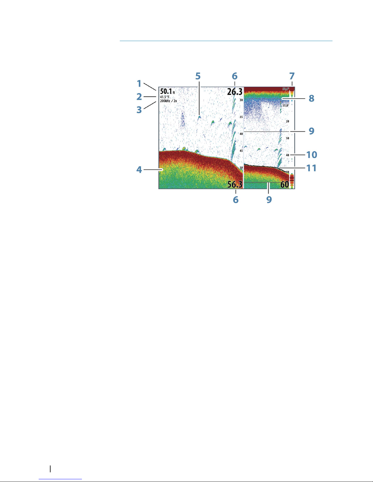
View options
The View menu allows you to display a split image, choose a predefined pallete, to change a
specific color on the image to white, to illustrate changes in water temperature, to show a
bottom line, amplitude scope and zoom bar.
1 Depth
2 Temperature
3 Frequency / Zoom level
4 Bottom
5 Fish arches
6 Upper and Lower range
7 A-Scope*
8 Temperature graph*
9 Zoom bars*
10 Range scale
11 Bottom line*
* Optional image items.
Ú
Note: You can turn the optional image items on/off individually as described in the
following sections.
4
16
View options | S2009-2016 Fish Finder User Manual
Page 17
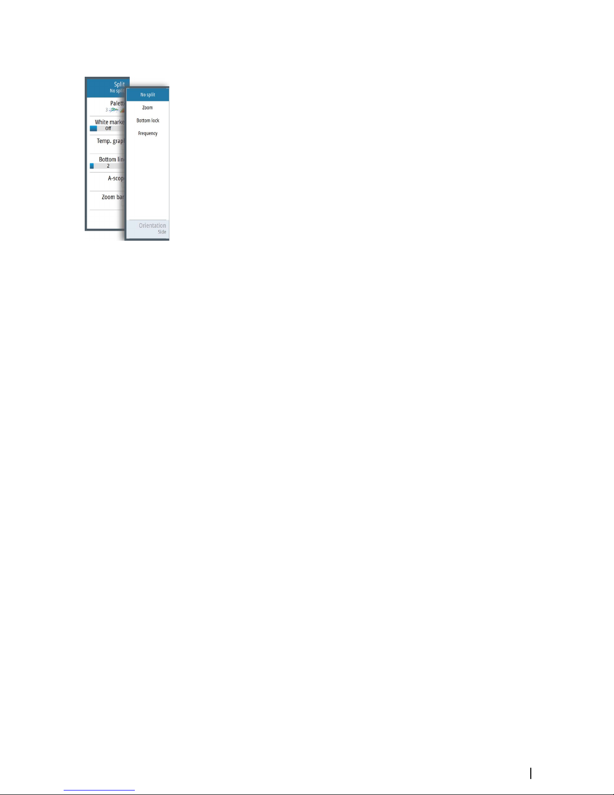
Split screen options
Split screen options are available on the split screen sub-menu.
Zoom
The Zoom mode presents a magnified view of the sounder image on the left side of the
panel.
You can select up to 8x zoom using the rotary knob.
The range zoom bars on the right side of the display shows the range that is magnified. If you
increase the zooming factor the range is reduced. You see this as reduced distance between
the zoom bars.
Activate the zoom bar option on the View menu to display the zoom bars. Activate and
move the cursor to pan history and view different depths of the water column. Refer to "Zoom
bars" on page 18.
Bottom lock
The bottom lock mode is useful when you want to view echoes close to the bottom. In this
mode the left side of the panel shows an image where the bottom is flattened. The range
scale is changed to measure from the seabed (0) and upwards. The bottom and the zero line
are always shown on the left image, independent of the range scale. The scaling factor for
the image on the left side of the panel is adjusted as described for the Zoom option.
Frequency
The frequency split screen option is only available if multiple frequencies are available.
The frequency mode is useful when you want to view higher and lower frequencies at the
same time.
• A low frequency, for example 50 kHz, will go deep. It generates a wide cone but is
somewhat more sensitive to noise. It is good for bottom discrimination and wide area
search.
• A high frequency, for example 200 kHz, offers higher discrimination and is less sensitive to
noise. It is good for separating targets and for higher speed vessels.
On a frequency split screen image, press the rotary knob to toggle between the left-side and
right-side images. The active image has an orange frame around it. Press the frequency
Softkey and turn the rotary knob to adjust the frequency on the split screen image that is
active. You can use most softkey options to change the range, gain, color, etc. to the split
screen image that is active.
Orientation
Orientation is only available if the Frequency split screen option is used.
You can specify to show the split screens on top of each other or side-by-side.
No split
To revert to a single image select No split in the Split sub-menu.
Palettes
You can select between several display palettes optimized for a variety of fishing conditions.
View options | S2009-2016 Fish Finder User Manual
17
Page 18

White marker
Use this option to change a specific color on the image to white. This effectively highlights
(or hides) the selected color.
Temperature graph
The temperature graph is used to illustrate changes in water temperature.
When toggled on, a colored line and temperature digits are shown on the Echosounder
image.
Bottom line
A bottom line can be added to the bottom surface to make it easier to distinguish the
bottom from fish and structures.
Toggle enable/disable the Bottom line from the bottom line sub-menu. Turning the rotary
knob or pressing the up/down arrow keys moves the slide bar up/down and specifies the
thickness of the bottom line.
A-Scope
The A-scope is a display of real-time echoes as they appear on the panel. The strength of the
actual echo is indicated by both width and color intensity.
Zoom bars
The zoom bars are displayed when you activate a split zoom image and activate the zoom
bar on the View menu. Refer to "Zoom" on page 17.
The range zoom bars on the right side of the display shows the range that is magnified and
displayed on the left side. If you increase the zooming factor, the range is reduced. You see
this as reduced distance between the zoom bars.
You can move the zoom bars on the right side up or down to cause the left side image to
show different depths of the water column.
• You activate the cursor and display the cursor icon by pressing the left or right arrow keys
• You deactivate the cursor and remove the cursor icon from the image by pressing the
Clear cursor softbar key or the Exit key
• You move the cursor within the image by pressing the arrow keys. Move the cursor left/
right to pan history. Move the cursor up/down to view different depths of the water
column in the zoom panel.
18
View options | S2009-2016 Fish Finder User Manual
Page 19

Alerts
The system continuously checks for dangerous situations and system faults while the system
is running. When an alert situation occurs, an alert message pops up on the screen. and an
alert icon is displayed in the status bar.
If you have enabled the siren, the alert message is followed by an audible alert.
The alert is recorded in the alert listing so that you can see the details and take the
appropriate corrective action.
The active, historical and settings dialogs are available from the main menu and from the
Alert Settings dialog.
• Active - list of active alerts.
• History - list of all alerts with time stamp.
• Settings - list of all available alert options in the system, with current settings.
The following is an example of an alert message.
Acknowledging an alert message
The close option is available in the alert dialog for acknowledging a message.
Close sets the alert state to acknowledged, meaning that you are aware of the alert
condition. The siren stops and the alert dialog is removed. However, the alert remains active
in the alert listing until the reason for the alert has been removed.
5
Alerts | S2009-2016 Fish Finder User Manual
19
Page 20

Advanced options
Noise rejection
Signal interference from bilge pumps, engine vibration and air bubbles can clutter the
image.
The noise rejection option filters the signal interference and reduces the on-screen clutter.
TVG
Wave action, boat wakes and temperature inversions can cause onscreen clutter near the
surface. The TVG (Time Variable Gain) option reduces surface clutter by decreasing the
sensitivity of the receiver near the surface.
Ú
Note: For optimal image return and clarity in most conditions, the default value is set to
a low value.
Scroll speed
You can select the scrolling speed of the image on the screen. A high scroll speed updates
the image fast, while a low scroll speed presents a longer history.
Ú
Note: In certain conditions it may be necessary to adjust the scroll speed to get a more
useful image. Such as adjusting the image to a faster speed when vertically fishing
without moving.
Ping speed
Ping speed controls the rate the transducer transmits the signal into the water. By default,
the ping speed is set to max. It may be necessary to adjust the ping speed to limit
interference or to adjust for specific fishing conditions.
Recording log data
Start recording log data
You can start recording log data and save the file internally in the unit, or save it onto a card
inserted into the unit’s card reader.
The record function is activated from the Advanced menu option.
When the data is being recorded, there is a flashing red symbol in the top left corner and a
message appears periodically at the bottom of the screen.
When you select Record in the Advanced menu, the Record sonar log dialog is displayed
where you specify recording settings. The options are explained in the following topics.
Filename
Specify the name of the recording (log).
File format
Ú
Note: XTF format is for use only with select 3rd party Echosounder viewing tools.
6
20
Advanced options | S2009-2016 Fish Finder User Manual
Page 21

Save to
Select whether the recording is to be saved internally or to a memory card in the card reader.
Bytes per sounding
Select how many bytes per seconds that are to be used when saving the log file. More bytes
yield better resolution, but cause the record file to increase in size compared to using lower
byte settings.
Time remaining
Shows the remaining allocated space available for recordings.
Stop recording log data
Select Stop in the Record sonar log dialog to fully stop the recording of all log data. The
Record sonar log dialog is activated by selecting the record option in the Advanced menu.
Viewing recorded log data
Use the Simulator to view recorded logs. Both internally and externally stored sounder
records may be reviewed when selected in the simulator.
You stop viewing the recorded image by turning off the simulator. Refer to "Simulator" on page
23.
Advanced options | S2009-2016 Fish Finder User Manual
21
Page 22

Files
File management system, used to browse the contents of the unit's internal memory and
inserted SD card.
Managing files
Select the files option in the Main menu to open the Files dialog.
You can copy, rename, and delete files. You can transfer files (such as log data recordings,
screen capture images, system settings, etc.) from the unit to a memory card in the card
reader using the copy option and vice-versa.
Exporting the log file
The log file can be exported from the Files dialog to a memory card in the card reader. Refer
to "NMEA Data logging" on page 46.
7
22
Files | S2009-2016 Fish Finder User Manual
Page 23

Simulator
The simulation feature lets you see how the unit works in a stationary position and without
being connected to the transducer, or other devices.
Use the simulator to become familiar with your unit before using it on the water.
The status bar indicates if the simulator is toggled on.
Turning the simulator on/off
Select the simulator option to toggle the simulator on/off. A check-mark in the check box
indicates the simulator is running.
Simulator source files
You can select which data files are used by the simulator. A set of source files is included in
your system, and you can import files by using a card inserted into the card reader. You can
also use your own recorded log data files in the simulator.
8
Simulator | S2009-2016 Fish Finder User Manual
23
Page 24

Installation
Mounting location
Choose the mounting locations carefully before you drill or cut. The unit should be mounted
so that the operator can easily use the controls and clearly see the screen.
Do not mount the S2016 in an outside location exposed to direct sunlight, it is intended for
pilothouse installation only. The S2009 may be mounted both inside, or outside in direct
sunlight due to its high brightness screen.
Ensure that any holes cut are in a safe position and will not weaken the boat’s structure. If in
doubt, consult a qualified boat builder, or marine electronics installer.
Before cutting a hole in a panel, make sure that there are no hidden electrical wires or other
parts behind the panel.
Check that it is possible to route cables to the intended mounting location.
Leave sufficient clearance to connect all relevant cables.
Do not mount any part where it can be used as a hand hold, where it might be submerged,
or where it will interfere with the operation, launching, or retrieving of the boat.
For overall width and height requirements, refer to "Dimensional drawings" on page 50.
Good ventilation is required. Choose a location that will not expose the unit to conditions
that exceed the specifications - refer to "Technical specifications" on page 48.
Warning: When installing, ensure appropriate safety equipment is used.
For example, ear muffs, protective glasses, gloves and a dust mask. Power
tools may exceed safe noise levels, and can cast off dangerous projectiles.
The dust from many materials commonly used in boat construction may
cause irritation or damage to eyes, skin, and lungs.
9
24
Installation | S2009-2016 Fish Finder User Manual
Page 25

Viewing angle
The viewing angle influences the viewability of the monitor. The recommended viewing
angles relative to perpendicular are shown in the illustrations below.
C
C
A
A
30°
80°
9"
C
C
A
A
80°
80°
9"
C
C
A A
80° 80°
16"
Horizontal viewing angles
45°
A
40°
70°
20°
45°
C
B
C
40°
70°
20°
70°
40°
20°
16"
Vertical viewing angles
A Optimum viewing angle
B Good viewing angle
C Poor viewing angle or obstructed view
Ú
Note: Installations requiring better left hand visibility on the 9" unit can optimize the
display for viewing from the left. Refer to "Optimize for left-hand view" on page 38.
Safe distance
Ensure unit is not installed too close to devices that may emit harmful interference, or
devices that may be sensitive to any electromagnetic field disruption caused by the unit.
Typical minimum safe distances are indicated below.
2.0 m (6.5 ft) Min
1.0 m (3 ft) Min
1.5 m (5 ft) Min
1
2 2 2
3
4
1 Radio or AIS transmitter
2 Control unit
Installation | S2009-2016 Fish Finder User Manual
25
Page 26
3 Radar
4 Compass
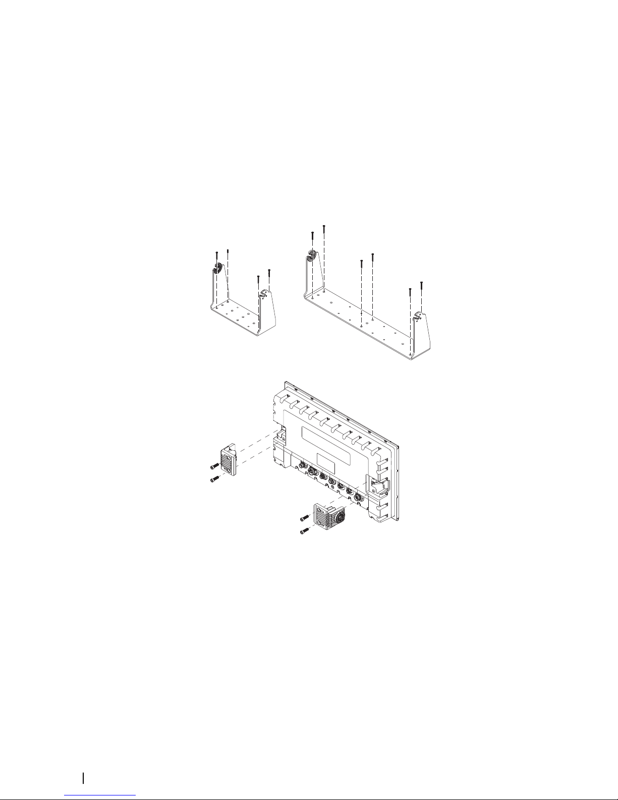
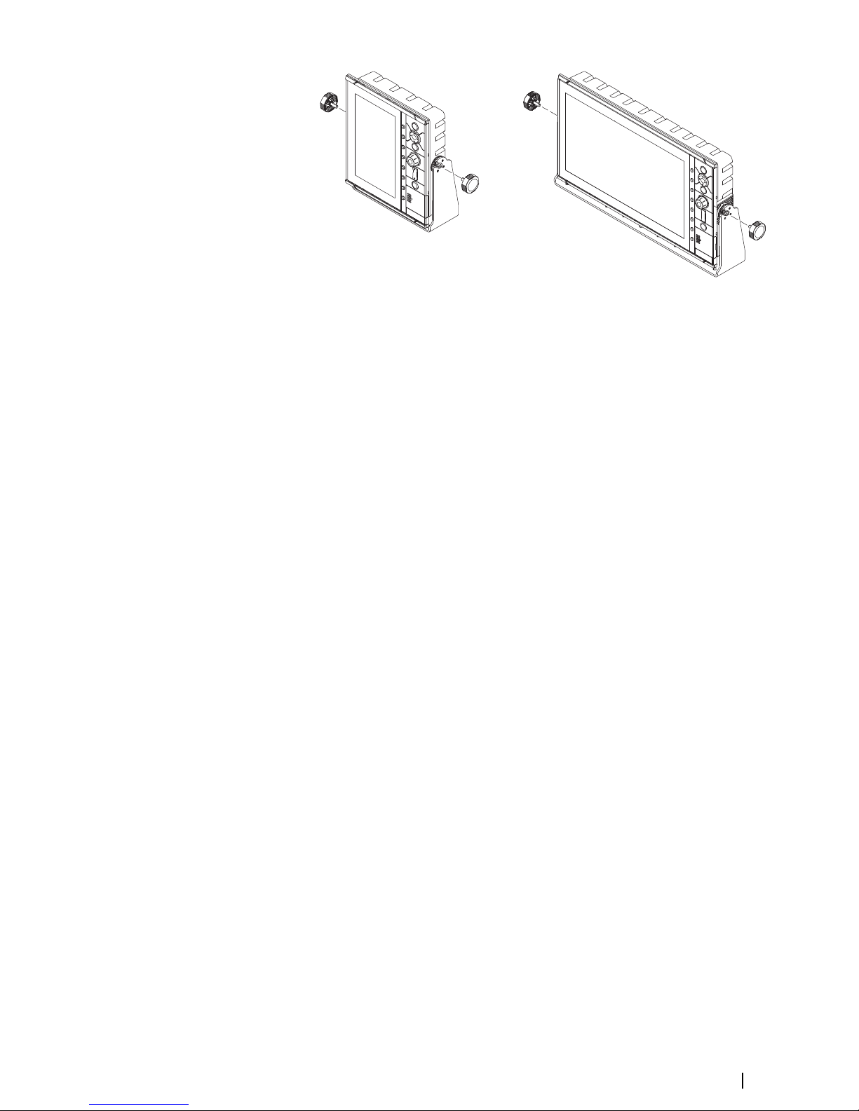
U-bracket mounting
1. Place the bracket in the desired mounting location. Ensure that the chosen location has
enough height to accommodate the unit fitted in the bracket, and allows tilting of the
unit. Also adequate space is required on both sides to allow tightening and loosening of
the knobs.
2. Mark the screw locations using the bracket as a template, and drill pilot holes. Use
fasteners suited to the mounting surface material. If the material is too thin for selftappers, reinforce it, or mount the bracket with machine screws and large washers. Use
only 304 or 316 stainless steel fasteners.
3. Screw down the bracket.
4. (16" units only) Using the screws provided in the gimbal kit, fasten the gimbals to the unit.
5. Mount the unit to the bracket using the knobs. Hand tighten only. The ratchet teeth in the
bracket and unit case ensure a positive grip and prevent the unit from changing from the
desired angle.
26
Installation | S2009-2016 Fish Finder User Manual
Page 27
Panel mounting
The screws and gasket used for panel mounting are included in the box. For mounting
instructions, refer to the Panel mounting template.
Installation | S2009-2016 Fish Finder User Manual
27
Page 28

Wiring
Guidelines
Don't:
• make sharp bends in the cables
• run cables in a way that allows water to flow down into the connectors
• run the data cables adjacent to radar, transmitter, or large/high current carrying cables or
high frequency signal cables.
• run cables so they interfere with mechanical systems
Do this:
• make drip and service loops
• use cable-tie on all cables to keep them secure
• solder/crimp and insulate all wiring connections if extending or shortening the cables.
Extending cables should be done with suitable crimp connectors or solder and heat
shrink. Keep joins as high as possible to minimize possibility of water immersion.
• leave room adjacent to connectors to ease plugging and unplugging of cables
Warning: Before starting the installation, be sure to turn electrical power
off. If power is left on or turned on during the installation, fire, electrical
shock, or other serious injury may occur. Be sure that the voltage of the
power supply is compatible with the unit.
Warning: The positive supply wire (red) should always be connected to
(+) DC with the supplied fuse or a circuit breaker (closest available to fuse
rating).
Rear connections
ETHERNET
NMEA2000
POWER
NMEA0183
1 3 4 5
6
ECHO
S2009 Rear connections
ETHERNET NMEA2000 POWER NMEA0183
ECHO
HDMI
1
2
3
4
5 6
S2016 Rear connections
1 Ethernet, 5-pin
2 HDMI (available on S2016 only)
3 NMEA 2000, 5-pin
4 Power, 4-pin
5 NMEA 0183, 8-pin
6 ECHO, 7-pin
28
Installation | S2009-2016 Fish Finder User Manual
Page 29
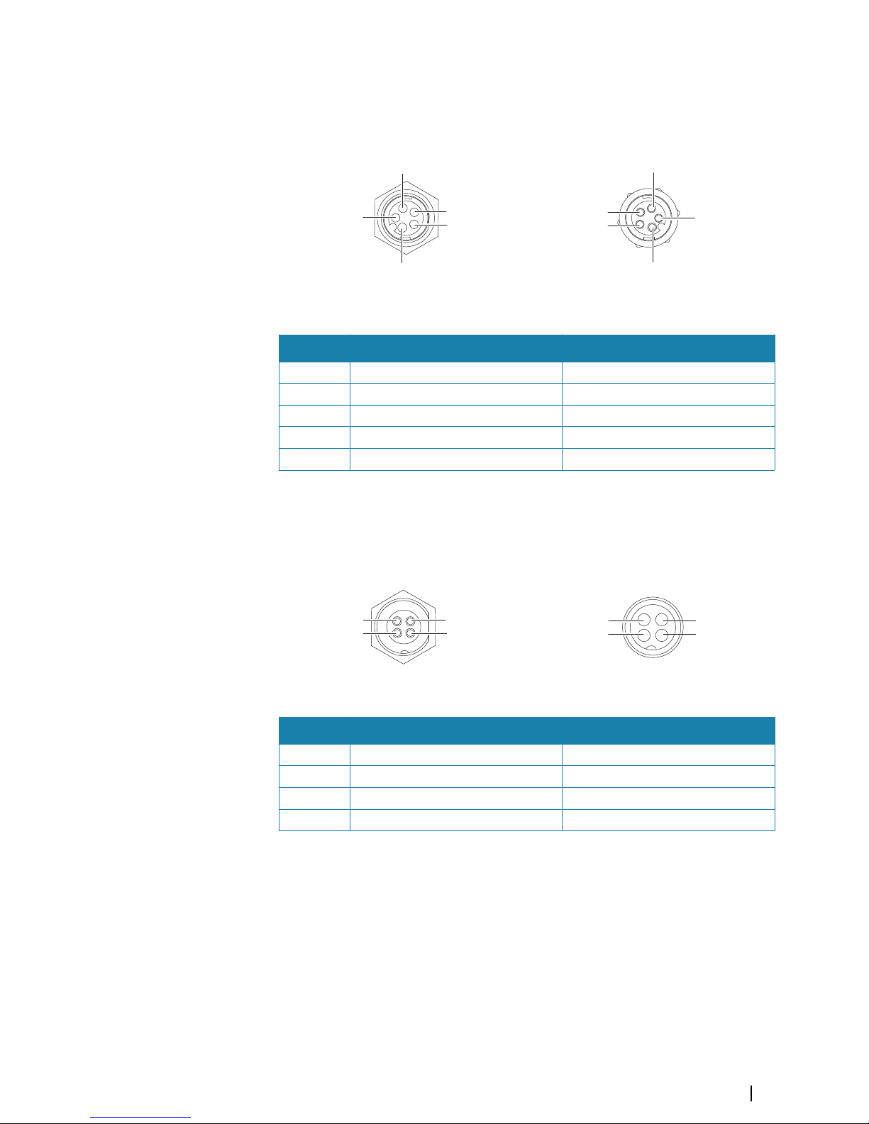
Ethernet connector
The unit is equipped with an Ethernet port, which allows connecting the unit to your
network using the 5 pin Ethernet connector.
1
2
3
4
5
Unit socket (female)
2
3
1
4
5
Cable plug (male)
Key Purpose Color
1 Transmit positive TX+ Blue/White
2 Transmit negative TX- Blue
3 Receive positive RX+ Orange/White
4 Receive negative RX- Orange
5 Shield Bare
Power connection
The unit is designed to be powered by a 12 or 24 VDC system. It is protected against reverse
polarity, under voltage and over voltage (for a limited duration). A fuse should be fitted to the
positive supply; 2 A for the 9" model and 5 A for the 16" model.
3
4
1
2
Unit socket (male)
1
2
3
4
Cable plug (female)
Key Purpose Color
1 -12/24 VDC Black
2 External alarm Blue
3 Power control Yellow
4 +12/24 VDC Red
Power Control connection
The yellow Power Control wire in the power cable is an input that will turn on the unit when
power is applied.
Power Control unconnected
Device will turn on and off when the power button on the front of the unit is pressed. Leave
the yellow Power Control wire disconnected and tape or heat-shrink the end to prevent
shorting.
Power Control to supply positive (auto on)
Device will turn on immediately when power is applied. Common the yellow wire with the
red wire after the fuse.
Installation | S2009-2016 Fish Finder User Manual
29
Page 30
Ú
Note: The unit cannot be powered down by power button, but can be put in to standby
mode. (The screen backlight turns off.)
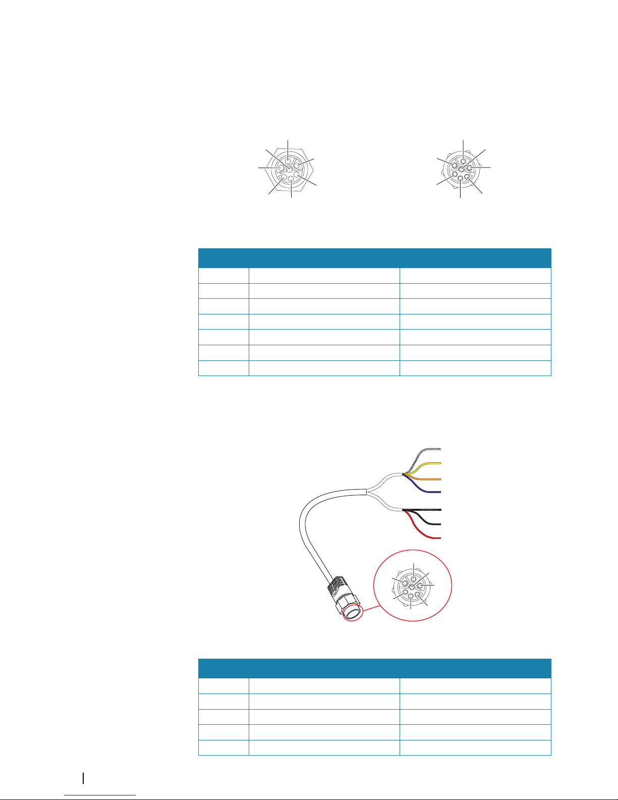
Echo connector
The unit is equipped with an Echo (transducer) port for a 7-pin transducer connector.
1
2
3
4
5
6
7
Unit socket (female)
1
2
3
4
5
6
7
Cable plug (male)
Key Purpose Color
1 Depth + Red
2 Speed signal Blue
3 Speed volts Orange
4 Temp + Yellow
5 Depth - Black
6 Depth Gnd (shield) Bare
7 Temp - (shield) Bare
Transducer adapter cables
For transducers that do not have Navico blue 7 Pin connector that require the connector to
be removed. Use the part no. 000-10046-001, 7-pin to bare wire adapter cable.
1
5
6
2
3
4
7
1
2
3
4
5
6
7
Cable plug (male)
Key Purpose Color
1 Depth + Red
2 Speed signal Blue
3 Speed volts Orange
4 Temp + Yellow
5 Depth - Black
30
Installation | S2009-2016 Fish Finder User Manual
Page 31
Key Purpose Color
6 Depth Gnd (shield) Bare
7 Temp - (shield) Bare
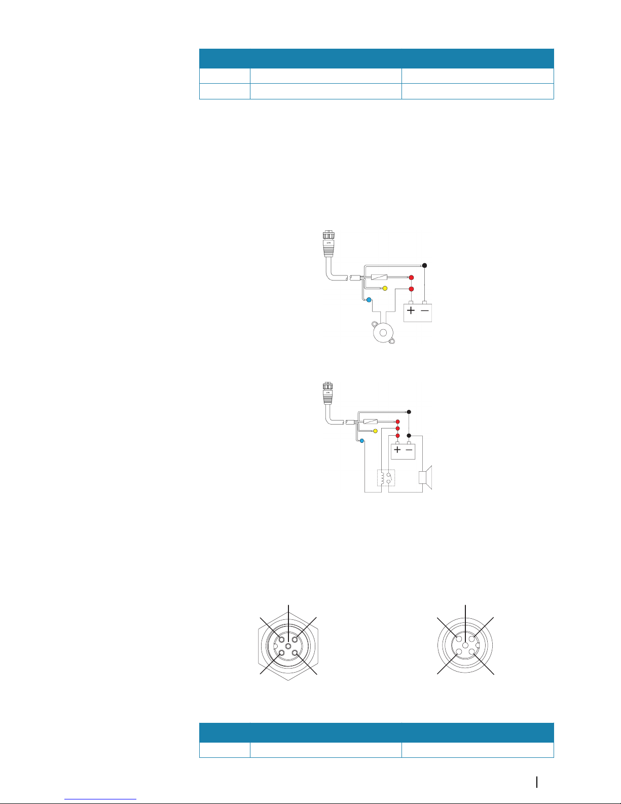
External alarm
The external alarm can be a small piezo buzzer connected directly, or a horn siren connected
through a relay.
Alarms are configured globally in the system. That is, they can be configured on any one
networked multifunction device or instrument, and be seen, heard, and acknowledged from
all devices. Individual devices can also be configured to not sound their internal buzzer, but
still display the alarm information. For information about configuring alarms, refer to the
Alarms section in the Operator Manual.
For sirens that draw more than 1 Amp, use a relay.
NMEA 2000 backbone
NMEA 2000 Device connection
The NMEA 2000 data port allows the receiving and sharing of a multitude of data from
various sources.
4
3
5
1
2
Unit socket (male)
1
2
5
4
3
Cable plug (female)
Key Purpose Color
1 Shield Drain
Installation | S2009-2016 Fish Finder User Manual
31
Page 32

Key Purpose Color
2 NET-S (+12 VDC) Red
3 NET-C (- 12 VDC) Black
4 NET-H White
5 NET-L Blue
Planning and installing a network backbone
The backbone needs to run between the locations of all products to be installed - typically in
a bow to stern layout - and be no further than 6 m from a device to be connected.
Choose from the following components to make up the backbone:
• Micro-C cables: 0.6 m (2 ft), 1.8 m (6 ft), 4.5 m (15 ft), and 7.6 m (25 ft) cables.
• T-connector or 4-way connector. Used to connect a drop cable to the backbone.
• Micro-C power cable. Connect to the backbone at a position that is central to the network
load using a T-connector or 4-way connector.
Ú
Note: When using a wind sensor, the mast cable should be connected at one end of the
backbone, as the sensor is fitted with a termination resistor.
Ú
Note: Most NMEA 2000 devices can be connected directly to a SimNet backbone and
SimNet devices can be connected to a NMEA 2000 network by using adapter cables.
Power the network
The network requires its own 12 V DC power supply protected by a 3 amp fuse or breaker.
Connect power at any location in the backbone for smaller systems.
For larger systems introduce power at central point in the backbone to “balance” the voltage
drop of the network.
Ú
Note: If joining to an existing NMEA 2000 network that already has its own power
supply, do not make another power connection elsewhere in the network, and ensure
the existing network is not powered by 24 V DC.
Ú
Note: Do not connect the NMEA 2000 power cable to the same terminals as the engine
start batteries, autopilot computer, bow thruster or other high current devices.
The following drawing demonstrates a typical small network. The backbone is made up of
directly interconnected T-connectors.
+
_
1
2 V DC
T
3
44
6
2
1
T
5
1 NMEA 2000 device
2 Connector to unit
3 Drop-cable, should not exceed 6 m (20 ft)
32
Installation | S2009-2016 Fish Finder User Manual
Page 33

4 Terminators
5 Backbone
6 Power cable
NMEA 0183 device connection
The unit has an NMEA 0183 serial port, providing both an input and an output. The port uses
the NMEA 0183 (serial balanced) standard, and can be configured in the software for different
baud rates up to 38,400 baud.
NMEA 0183 serial cable
Cable labelled: 032-0080-08. Spare part number: 000-11247-001.
1
2
6
7
8
3
4
5
Unit socket (male)
1
2
6
7
3
4
5
8
Cable plug (female)
Key Port Purpose Color
1 Port 2 Listener B (Rx+) Brown/White
2 Port 2 Listener A (Rx-) Brown
3 Port 2 Talker B (Tx+) Green/White
4 Port 2 Talker A (Tx-) Green
5 Port 1 Talker B (Tx+) Orange/White
6 Port 1 Talker A (Tx-) Orange
7 Port 1 Listener A (Rx-) Blue/White
8 Port 1 Listener B (Rx+) Blue
Talkers and Listeners
Do not connect multiple devices outputting data (Talkers) on to any serial input (RX) of the
unit. The RS422 protocol is not intended for this type of connection, and data will be
corrupted if more than one device transmits simultaneously. The output (TX) however may
drive multiple receivers (Listeners). The number of receivers is finite, and depends on the
receiving hardware. Typically three devices is possible.
Connect an external monitor
The S2016 incorporates HDMI technology and has a HDMI output which can be connected
to an external monitor to replicate video at a remote location. Video is at a resolution of 1366
x 768, a connected monitor should support same resolution or be able to scale.
Installation | S2009-2016 Fish Finder User Manual
33
Page 34

1
3
2
4
ETHERNET NMEA2000 POWER
NMEA0183 ECHOHDMI
HDMI-1 DVI-2
VIDEO-3 VIDEO-4NMEA2K
SERIAL USB
POWER
1 MO series monitor
2 HDMI cable
3 S2016
4 HDMI cable - waterproof connector (use in exposed installations)
Ú
Note: While the HDMI standard does not state maximum cable length, signal may be
compromised on long runs. Only use Navico or other high quality HDMI certified cables.
3rd party cables should be tested before installation. On runs over 10m it may be
required to add an HDMI amplifier or use HDMI-CAT6 adaptors.
Ú
Note: Some HDMI TV displays may apply over-scan, which will in effect crop the image
possibly causing loss of important content. Check the display manual for an option to
disable over-scan or adjust scaling
34
Installation | S2009-2016 Fish Finder User Manual
Page 35

System diagrams
Basic system setup example
+
_
TT
+
_
12 / 24 V DC
12 V DC
S2009 or S2016
ETHERNET NMEA2000 POWER NMEA0183 ECHO
ETHERNET NMEA2000 POWER NMEA0183
ECHO
HDMI
Installation | S2009-2016 Fish Finder User Manual
35
Page 36

Large system setup example
+
_
TT
+
_
12 / 24 V DC
MO-16
S2009 or S2016
MO-16
NSO evo2
HS70
12 V DC
+
_
12 / 24 V DC
ETHERNETNMEA2000 POWER NMEA0183 ECHO
ETHERNET NMEA2000 POWER NMEA0183
ECHO
HDMI
HDMI-1 DVI-2
VIDEO-3 VIDEO-4 NMEA2K
SERIAL USB
POWER
HDMI-1 DVI-2
VIDEO-3 VIDEO-4 NMEA2K
SERIAL USB
POWER
36
Installation | S2009-2016 Fish Finder User Manual
Page 37

Software Setup
The system requires some initial configuration before use and in order to get the most out of
the product. You can change the settings later, as conditions change and as you become
more familiar with the product.
Select the settings menu option to access configurable items described in the following
sections.
Wiring and mounting information are provided in the separate installation instructions for
the unit.
System settings
Use the system settings dialog to set basic settings as described below. Some settings can
require a reboot of the system.
Language
Controls the language used on this unit for panels, menus, and dialogs. Changing the
language causes the unit to restart.
Text size
Used for setting the text size in menus and dialogs.
Default setting: Normal
Key beeps
Controls the loudness of the beep sound when a key is pressed.
Default setting: Loud
Time
Controls the local time zone offset, and the format of the time and date.
Restore defaults
Allows you to select which settings are to be restored to their original factory settings.
Coordinate system
Several coordinate systems can be used to control the format for latitude and longitude
coordinates displayed on the chart panel.
Magnetic variation
Magnetic variation is the difference between true bearings and magnetic bearings, caused
by different locations of the Geographic and the Magnetic north poles. Any local anomalies
such as iron deposits might also affect the magnetic bearings.
10
Software Setup | S2009-2016 Fish Finder User Manual
37
Page 38

When set to Auto, the system automatically converts magnetic north to true north. Select
manual mode if you need to enter your own local magnetic variation.
Phantom Loran
Enables use of Phantom Loran positioning system.
Loran settings
Defines Loran chains (GRI) and preferred station for waypoint entry, cursor position and
position panel.
The graphic example shows a cursor position window with Loran position information.
For more information refer to your Loran system documentation.
Optimize for left-hand view
This option is available for the S2009 only. To access the option select Advanced and then
the User Interface option in the Settings dialog.
Select this option to optimize the display for viewing from the left.
About
Displays copyright information, software version, and technical information for this unit.
Echo settings
Echosounder source
If you have Network Echosounder enabled and have more than one Echosounder on your
network, you can select which Echosounder to be the preferred source on this unit.
Network Echosounder
You can share the Echosounder images from this unit with other units connected on the
Ethernet network.
Heave compensation
Compensates for the wavy appearance of items in the Echosounder image as the vessel
heaves with waves.
Ú
Note: This option is only available if a compatible heading sensor with heave
compensation output is available.
Search depth
Noise may cause the Echosounder to search for unrealistic depths.
By setting the search depth manually the system displays echoes received from objects
within the set depth range.
38
Software Setup | S2009-2016 Fish Finder User Manual
Page 39

Installation
Use the installation option in the Echo settings dialog to setup the echosounder.
Keel offset
All transducers measure water depth from the transducer to the bottom. As a result, water
depth readings do not account for the distance from the transducer to the lowest point of
the boat (for example; bottom of the keel, rudder, or propeller) in the water or from the
transducer to the water surface.
Set the keel offset to the distance from the bottom of the transducer to the lowest point of
the boat in the water. If, for example, the distance is 0.3 m (1 ft), it will be input as (minus) -
0.3 m (-1 ft).
Water speed calibration
Water speed calibration is used to adjust the speed value from the paddle wheel to match
the actual boat speed through the water. Actual speed can be determined from GPS speed
over ground (SOG) or by timing the boat over a known distance. Water speed calibration
should be performed in calm conditions, with minimal wind and current movement.
Increase this value above 100 % if the paddle wheel is under reading, and decrease this value
if it is over reading. For example, if the average water speed reads 8.5 knots (9.8 MPH) and
SOG records 10 knots (11.5 MPH) the calibration value needs to be increased to 117 %. To
calculate the adjustment, divide the SOG by the paddlewheel speed, and multiply the
product by 100.
Calibration range: 50-200 %. Default is 100 %.
Water speed averaging
Averages water speed by measuring your speed at a selected interval of time. Water speed
intervals range from one to thirty seconds. For example if you select five seconds, your
displayed water speed will be based on averaging over 5 seconds of sampling.
Calibration range: 1-30 seconds. Default is 1 second.
Water temperature calibration
Temperature calibration is used to adjust the water temperature value from the sonar
transducer to match the data from another temperature sensor. It may be required to correct
for localized influences to the measured temperature.
Calibration range: -9.9° - +9.9°. Default is 0°.
Ú
Note: Water temperature calibration only appears if the transducer is temperature
capable. Check transducer type selection if this option should be available.
Software Setup | S2009-2016 Fish Finder User Manual
39
Page 40

Transducer type
Transducer type is used for selecting the transducer model connected to the sonar module.
The transducer selected will determine what frequencies the user can select during sonar
operation. In some transducers with built-in temperature sensors, the temperature reading
may be inaccurate or not available at all if the wrong transducer is selected. Transducer
temperature sensors are one of two impedances - 5k or 10k. Where both options are given
for the same model transducer, refer to paperwork supplied with transducer to determine
impedance.
Alerts settings
You can access the Alerts settings dialog from the Alerts option in the Main menu and from
the Settings option in the Main menu.
Use the Alerts settings dialog to turn on/off alerts and set conditional values. You can also
enable the internal siren.
For more information about the alert message pop-up, and active and historical alert
messages, refer to "Alerts" on page 19.
Units settings
Use the units settings dialog to specify the units of measure displayed.
Network settings
The unit has Ethernet, NMEA 0183 and NMEA 2000 port connections on the back allowing
you to connect the unit to your network. Use the Network settings dialog to setup networks
and connect to network devices.
40
Software Setup | S2009-2016 Fish Finder User Manual
Page 41

Info
Displays the Ethernet connection status, the unit's IP and MAC addresses.
Device name
Assigning a name is useful in systems using more than one device of the same type and size.
When viewing data sources or the device list, the assigned name will append the default
product name + virtual device function for easy identification.
Data source selection
Ú
Note: If NMEA 0183 is used, complete the NMEA 0183 setup prior to doing source
selection. Refer to "NMEA 0183 setup" on page 44.
Data sources provide live data to the system.
The data may originate from modules internal to the unit (for example internal GPS or sonar),
or external modules connected to the NMEA 2000 or via NMEA 0183 if available on the unit.
When a device is connected to more than one source providing the same data, the user can
choose the preferred source. Before commencing with source selection make sure all
external devices and the NMEA 2000 backbone are connected and are turned on.
Auto select data sources
The Auto select option looks for all sources connected to the unit. If more than one source is
available for each data type, selection is made from an internal priority list. This option is
suitable for the majority of installations.
Ú
Note: Auto data source selection may already have been selected at first time startup.
However, it should be redone if any new devices have been added to the network since.
Advanced data source selection
The advanced option allows for you to manually select or unselect data sources. Manual
selection is generally only required where there is more than one source for the same data,
and the ‘Auto select’ selected source is not the one desired.
Device list
The Device list shows the devices that provide data. This may include a module inside the
unit, or any external NMEA 2000 device.
Software Setup | S2009-2016 Fish Finder User Manual
41
Page 42
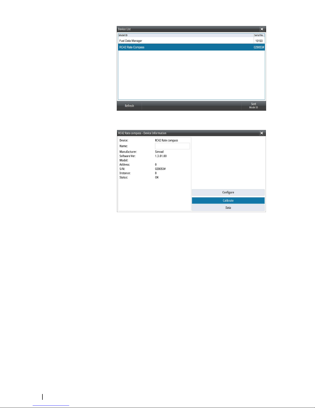
Selecting a device in this list will bring up additional details and actions:
All devices allow allocation of an instance number in the configure option. Set unique
instance numbers on any identical devices on the network to allow for the unit to distinguish
between them. The data option shows all data being output by the device. Some devices will
show additional options specific to the device.
Ú
Note: Setting the instance number on a 3rd party product is typically not possible.
Diagnostics
The NMEA 2000 tab on the diagnostics page can provide information useful for identifying
an issue with the network.
Ú
Note: The following information may not always indicate an issue that can be simply
resolved with minor adjustment to network layout or connected devices and their
activity on the network. However, Rx and Tx errors are most likely indicating issues with
the physical network, which may be resolved by correcting termination, reducing
backbone or drop lengths, or reducing the number of network nodes (devices).
42
Software Setup | S2009-2016 Fish Finder User Manual
Page 43
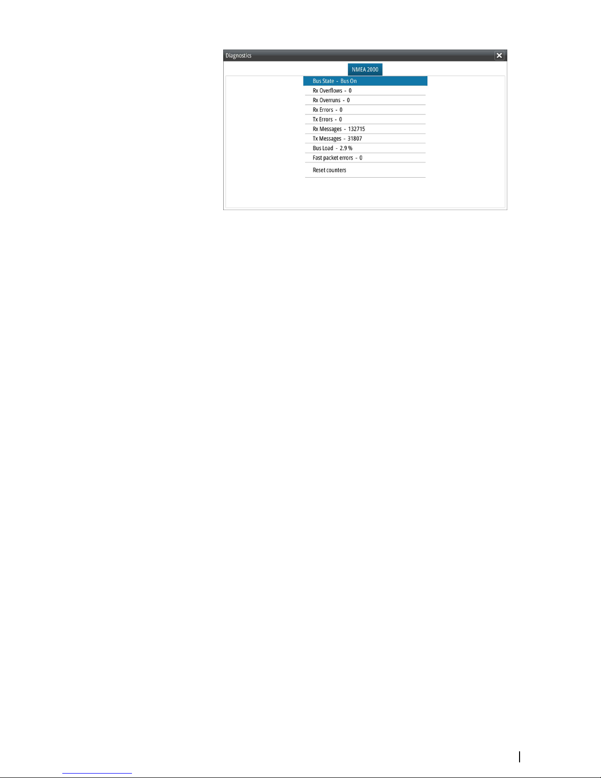
Bus state
Simply indicates whether the bus is powered, but not necessarily connected to any data
sources. However, if bus shows as ‘off’, but power is present along with an increasing error
count, it is possible that termination or cable topology is incorrect.
Rx Overflows
The unit received too many messages for its buffer before the application could read them.
Rx Overruns
The unit contained too many messages for its buffer before the driver could read them.
Rx/Tx Errors
These two numbers increase when there are error messages, and decrease when messages
are received successfully. These (unlike the other values) are not a cumulative count. Under
normal operation these should be at 0. Values around 96 upwards indicate a heavily error
prone network. If these numbers go too high for a given device, it will automatically drop off
the bus.
Rx/Tx Messages
Shows actual traffic in and out of device.
Bus Load
A high value here indicates network is near full capacity. Some devices automatically adjust
rate of transmission, if network traffic is heavy.
Fast Packet Errors
Cumulative counter of any fast packet error. This could be a missed frame, or a frame out of
sequence etc. NMEA 2000 PGNs are made of up to 32 frames. The entire message will be
discarded when a frame is missed.
Ú
Note: Rx and Tx Errors often indicate an issue with the physical network, which may be
resolved by correcting termination, reducing backbone or drop lengths, or reducing the
number of network nodes (devices).
Reset counters
Resets all counters in the NMEA 2000 tab of the Diagnostics dialog to zero. The counters start
recounting immediately.
SimNet Groups
The SimNet Group function is used to control parameter settings, either globally or in groups
of units. The function is used on larger vessels where several SimNet units are connected to
the network. By assigning several units to the same group, a parameter update on one unit
will have the same effect on the rest of the group members.
Software Setup | S2009-2016 Fish Finder User Manual
43
Page 44

Damping
If data appears erratic or too sensitive, damping may be applied to make the information
appear more stable. With damping set at MIN, the data is presented in raw form with no
damping applied. This is available for heading, course over ground, speed over ground,
apparent wind, true wind, boat speed, depth, and tide sourced from NMEA 2000.
Calibration
An offset (positive or negative) can be applied to correct inaccuracies in boat speed, sea
temp, air temp, barometric pressure, and depth sourced from NMEA 2000 devices.
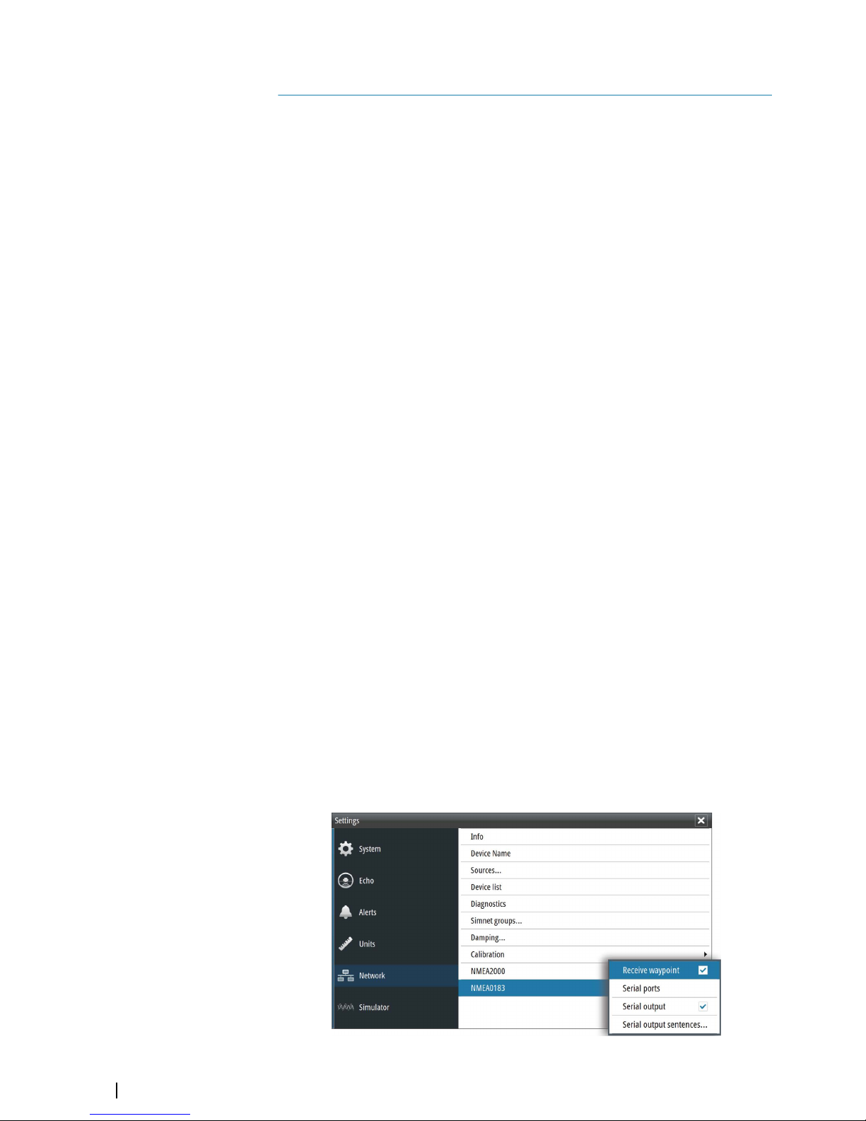
NMEA 2000
Use the NMEA 2000 network settings option to receive and send waypoints from or to NMEA
2000 devices.
NMEA 0183 setup
The NMEA 0183 port must be set to suit the speed of connected devices, and can be
configured to output only the sentences required by listening devices.
Receive waypoint
Select this option to allow a device capable of creating and exporting waypoints via NMEA
0183 to transfer directly to this unit.
Serial ports
Specify the baud rate for port for the devices connected to the NMEA 0183. The baud rate
should be set to correspond with devices connected to the NMEA 0183 input and output.
The input and output (Tx, Rx) use the same baud rate setting.
44
Software Setup | S2009-2016 Fish Finder User Manual
Page 45

Serial Output
Selection determines whether the data is output via Tx lines, and will enable editing of the
output sentences list.
Serial Output Sentences
This list allows control over which sentences need to be transmitted to other devices from
the NMEA 0183 port. Due to the limited bandwidth of NMEA 0183 it is desirable to only
enable the data that is required. The less sentences that are selected, the higher the output
rate of the enabled sentences.
Commonly used sentences are enabled by default.
Software Setup | S2009-2016 Fish Finder User Manual
45
Page 46
Maintenance
Preventive maintenance
The unit does not contain any field serviceable components. Therefore, the operator is
required to perform only a very limited amount of preventative maintenance.
It is recommended that you always fit the supplied protective cover when the unit is not in
use.
Cleaning the display unit
A proper cleaning cloth should be used to clean the screen, where possible. Use plenty of
water to dissolve and take away salt remains. Crystalized salt may scratch the coating if using
a damp cloth. Apply minimal pressure to the screen.
Where marks on the screen cannot be removed by the cloth alone, use a 50/50 mixture of
warm water and isopropyl alcohol to clean the screen. Avoid any contact with solvents
(acetone, mineral turpentine, etc.), or ammonia based cleaning products, as they may
damage the anti-glare layer or plastic bezel.
To prevent UV damage to the plastic bezel, it is recommended that the sun cover be fitted
when the unit is not in use for an extended period.
Cleaning the media port door
Clean the media port door regularly to avoid salt crystallization on the surface, causing water
to leak into the card slot.
Checking the keys
Make sure that no keys are stuck in the down position. If one is stuck, wiggle the key to free it
back to normal.
Checking the connectors
The connectors should be checked by visual inspection only.
Push the connector plugs into the connector. If the connector plugs are equipped with a
lock, ensure that it is in the correct position.
NMEA Data logging
All serial output sentences sent over the NMEA TCP connection are logged to an internal file.
You can export and review this file for service and fault finding purposes.
The maximum file size is predefined. If you have added several other files to the system (file
recordings, music, pictures, PDF files), this may reduce the allowed file size for the log file.
The system logs as much data as possible within the file size limitation, and then it starts
overwriting the oldest data.
11
46
Maintenance | S2009-2016 Fish Finder User Manual
Page 47

Exporting the log file
The log file can be exported from the files dialog.
When you select the Log database you are prompted to select a destination folder and
filename. Once accepted, the log file is written to the chosen location.
Software upgrades
The latest software is available for download from our website, navico-commercial.com/.
Detailed instructions for how to install the software are included in the upgrade files.
Backing up your system data
It is recommended to regularly copy your system settings files as part of your back-up
routine. The files can be copied to a card inserted in the card reader. Refer to "Files" on page
22.
Maintenance | S2009-2016 Fish Finder User Manual
47
Page 48

Technical specifications
Ú
Note: The most up-to-date specifications list is available at: navico-commercial.com/
Display
Display type LED-backlit Color TFT LCD
Display brightness S2009 = 1200 cd/m2
S2016 = 400 cd/m2
Display resolution S2009 = 480 x 800
S2016 = 1366 x 768
Display size S2009 = 9-inch portrait
S2016 = 16-inch landscape
Video integration (S2016 only) 1x HDMI output (Supported resolutions:
1366 x 768)
Overview
Output power 1 kW RMS
Echosounder Max Depths 3,000 m (10,000 ft), transducer-dependent
Echosounder Transducer Standard Broadband and single-channel
CHIRP Transducers
Echosounder Frequencies CHIRP 28-38 kHz, 40-60 kHz, 85-145 kHz,
130-210kHz
Broadband 28kHz, 38kHz, 50kHz, 83kHz,
200kHz
Technical/Environmental
Water Resistance IPX7
Operating Temperature - 15°C to +55°C (5°F to 131°F)
Dimensions Refer to "Dimensional drawings" on page 50
Weight S2009 = 2 kg (4.4 lb)
S2016 = 4 kg (8.8 lb)
Electrical
Power Supply (Supply Voltage) 12-24 V DC
Power Consumption S2009 = 11 W
S2016 = 20 W
Connectors
Power (10.8-31.2 V DC) 1 port, 4-pin
HDMI 1 port (S2016 only)
Echo (for transducer) 1 port, 7-pin
NMEA 2000 (compliant) 1 port, 5-pin
12
48
Technical specifications | S2009-2016 Fish Finder User Manual
Page 49

NMEA 0183 (compliant) 1 port, 8-pin. Supports 2x NMEA0183 ports.
Ethernet 1 port, 5 pin
Card reader
Card reader 1 SD card reader
Technical specifications | S2009-2016 Fish Finder User Manual
49
Page 50

Dimensional drawings
S2009
247 mm (9.72”)
224 mm (8.81”)
219 mm (8.62”)
80 mm
(3.14”)
67 mm
(2.63”)
100 mm (3.93”)
280 mm (11.02”)
260 mm (10.23”)
S2016
+
_
280 mm (11.02”)
80 mm
(3.14”)
67 mm
(2.63”)
100 mm (3.93”)
455 mm (17.91”)
477 mm (18.77”)
505 mm (19.88”)
13
50
Dimensional drawings | S2009-2016 Fish Finder User Manual
Page 51

Index
A
About this unit
38
Advanced select
Sources 41
Alert message
Acknowledging 19
Alerts, main menu option 19
Alerts
Settings 40
Auto gain 15
Auto hide
Softkey bar 13
Auto select
Sources 41
B
Backing up your system data 47
Bottom line 18
Bottom lock 17
Bracket mounting 26
C
Calibration
Offset network devices 44
Card reader 7
Color 15
Coordinate system 37
D
Damping 44
Data source selection 41
Device list 41
Device name 41
Diagnostics 42
Display illumination 12
E
Echosounder
A-Scope 18
F
Files, management 22
Files
Managing 22
First time startup
Setup wizard 12
Frequency 15
Split screen option 17
Front panel 7
Keys 7
Portrait and landscape 7
G
Gain 15
I
Illumination
12
Installation setup 39
Installation
Mounting 24
Instrument bar 12
Appearance 12
Edit the content 13
Turning on/off 13
K
Keel offset 39
Key beeps 37
L
Landscape front panels and displays 7
Language 37
Log file
Exporting 22
M
Magnetic variation 37
Main panel 8
Measuring distance 8
Mounting
Bracket 26
Location 24
Panel 27
N
Network settings 40
NMEA 2000 devices
Receive and send waypoints 44
NMEA Data logging 46
NMEA
Exporting log file 47
No split 17
Noise rejection 20
O
Offset network devices 44
Orientation
Split screen option 17
P
Palettes 17
Panel illustration 8
Panel mounting 27
Pausing the image 13
Phantom Loran 38
Settings 38
Ping speed 20
Portrait front panels and displays 7
Preventive maintenance 46
Index | S2009-2016 Fish Finder User Manual
51
Page 52

R
Range
14
Auto range 14
Recording log data 20
Stop 21
Viewing 21
Recording
Start recording log data 20
Reset counters 43
Restore defaults 37
S
Saving waypoints 9
Screen capture 13
Scroll speed 20
Search depth 38
Setup wizard
First time startup 12
SimNet Groups 43
Simulator 23
Source files 23
SL2 format 20
SLG format 20
Slide bars 10
Softkey bar
Auto hide 13
Hide 13
Software
Setup 37
Software upgrade 47
Sources
Advanced, manual selection 41
Auto select 41
Unselect 41
Split screen option
Frequency 17
Orientation 17
Split screen
No split 17
Options 17
Zoom 17
Stop recording log data 21
System Controls dialog 12
System Settings
About copyright and this unit 38
Coordinate system 37
Key beeps 37
Language 37
Magnetic variation 37
Text size 37
Time 37
T
Technical specifications 48
Temperature graph 18
Text size 37
Time 37
Transducer type 40
Turning the unit on and off 12
TVG
20
U
Units of measure 40
Using the cursor on the image 8
V
View options 16
Viewing history 9
Viewing recorded log data 21
W
Water speed averaging 39
Water speed calibration 39
Water temperature calibration 39
Waypoints
Saving 9
White marker 18
X
xtf format 20
Z
Zoom bars 18
Zooming the image 15
Zoom
Split screen option 17
52
Index | S2009-2016 Fish Finder User Manual
Page 53

Page 54

*988-10946-002*
www.navico-commercial.com
 Loading...