

Page 1

Installation manual
Simrad PI
Adapters for PI Spread and PI Remote
www.simrad.com
M A X I M I Z I N G Y O U R P E R F O R M A N C E A T S E A
Page 2

Document information
Rev Date Written by Checked by Approved by
Rev.B
18.02.05 RBr BØJ KR
Additional drawings and explanations added.
© 2005 Simrad AS.
ISBN 82-8066-043-7
All rights reserved. No part of this work covered by the copyright hereon may be
reproduced or otherwise copied without prior permission from Simrad AS.
The information contained in this document is subject to change without prior notice.
Simrad AS shall not be liable for errors contained herein, or for incidental or
consequential damages in connection with the furnishing, performance, or use of this
document.
The equipment to which this manual applies must only be used for the purpose for which
itwasdesigned.Improperuseormaintenancemay causedamagetotheequipment or injury
topersonnel. The usermustbefamiliar with the contents of the appropriate manualsbefore
attempting to operate or work on the equipment. Simrad AS disclaims any responsibility
fordamageorinjurycausedbyimproperinstallation,useormaintenanceof theequipment.
If you require maintenance on your Simrad equipment, contact your local dealer. You can
also contact Simrad using the following e-mail address: fish-support@simrad.com
Simrad AS
Strandpromenaden 50
Box 111
N-3191 Horten
Telephone: +47 33 03 40 00
Facsim il e: +47 33 04 29 87
M A X I M I Z I N G Y O U R P E R F O R M A N C E A T S E A
Page 3

INSTALLING SENSOR ADAPTORS
Introduction
The PI Spread and PI Remote sensor adaptors must be
properly installed, and their protective cages fabricated correctly
for the system to operate as designed. Misaligned sensors or
cages that interfere with the sensors’ communication signals will
negatively effect system performance. It is therefore highly
recommended that the installation of the PI Spread and PI
Remote sensor adapters not be hastily undertaken, but rather
carefully planed and then executed.
Installation manual
857-164919 / Rev.B
1
Page 4

Simrad PI Sensor adapter installation
Installation keypoints
The PI Spread sensor must be mounted on the port door.
The PI Remote sensor must be mounted on the starboard door.
The installation of the adapters must ensure that there is an
unobstructed line of sight between the sensor “eyes” for the
transverse communication link. Also, there must be a free line
of sight between the spherical head of the PI Spread sensor and
the vessel to ensure an operational communication link.
For bottom trawling, the sensor adapter should be mounted to
the upper part of the trawl door, and preferably at a place with
minor influence on the centre of gravity. Consult the trawl door
manufacturer or supplier if in doubt.
Adjust the tilt angle of the adapters according to your needs. 20
degrees is common for normal operation.
The adapter is designed to compensate for an angle of attack of
approximately 40 degrees. The templates also provide lower
angles.
Note The two rubber inserts provided must not be replaced with any
other types or designs. It is essential that these inserts provide a
secure cradle for the sensors, but they must also allow for free
water circulation to allow the sensor’s water switch to engage.
Also, the design of the inserts allows sand and mud to flow out
when the trawl doors are pulled up from the water.
The sensor adapters are manufactured from carbon steel, and
must be welded to the trawl doors. For mounting on wooden
trawl doors, dedicated mounting plates are available. The
adapters must be surface treated to withstand the wear and tear.
Weight
PI Spread adapter, weight in water without sensor: 9.8 kg
PI Spread adapter, weight in water with sensor: 12.5 kg
PI Remote adapter, weight in water without sensor: 8.8 kg
PI Remote adapter, weight in water with sensor: 10.1 kg
Optional supply
Mounting plate for PI Spread adapter for wooden door, use
order no. 599-207541.
Mounting plate for PI Remote adapter for wooden door, use
order no. 599-207551.
2
857-164919 / Rev.B
Page 5

Installation manual
The PI Spread and PI Remote
sensors:
(A) = Negative charging and
fastening lug
(B) = Positive charging and fastening
lug
(C) = Communication link to vessel’s
hydrophone. Free line of sight must
be provided.
(D) = Location of sensor lamp (rear
side on PI Spread)
(E) = Water switch sensor, must have
free access to the water once the door
and sensor is deployed.
(F) = Transverse communication link,
you must have free line of sight
between the Spread and Remote
sensors.
Trawl doors seen from the vessel:
(A) = Port door, (B) = Starboard door, (C) = PI Spread sensor, (D) = PI Remote sensor
(E) = Transverse communication link, must have free line of sight between the Spread
and Remote sensors.
857-164919 / Rev.B
3
Page 6

Simrad PI Sensor adapter installation
Location of sensor
adapters:
(A) = Starboard door
(B) = Port door
(C) = PI Remote sensor
adapter (499-207615)
(D) = PI Spread sensor
adapter (499-207613)
(E) = A protection cage is
highly recommended for
both adapters. It can be
manufactured from ø20
mm bars. Consider easy
access to release
mechanism and security
wire.
(F) = Angle of attack
(G) = 20 degrees tilt
angle
(H) = Communication
link to vessel’s
hydrophone
(I) = Transverse
communication link
(J) = Direction of tow
4
857-164919 / Rev.B
Page 7

Installation manual
Before work begins
Proper preparation involves becoming familiar with all related
documentation including:
• Drawings 830-208247 and 830-208246 in full size (1:1)
printout.
With the proceeding information in mind:
• Determine the optimal sensor placement and orientation with
regard to the intended operation of the vessel.
• Use the following procedures as a guide to create a specific
work plan for the doors in question.
• Discuss and clarify all phases of the operation with the
metalworker(s) performing the installation before beginning.
Procedure
Observe the procedure on the next pages.
Note The information contained in this procedure is to be used as a
guide. Deviations from the procedures listed may be necessary
to accommodate a specific installation.
857-164919 / Rev.B
5
Page 8

Simrad PI Sensor adapter installation
STEP 1: Cut openings in the doors for the sensor
adapters
Using drawing 830-208247 as a guide, and mark off the areas to
be cut out. Note that you need to have the drawing available in
size 1:1.
Cut openings in the doors using an acetylene torch, check their
accuracy against the full scale drawings when finished.
6
857-164919 / Rev.B
Page 9

Installation manual
2) Orient the sensor adapters
Position the sensor adapters (port and starboard respectively)
with the bottom portion just protruding through the back side of
the door.
Carefully check that the adapters’ angle and orientation are as
close to those described in the drawings.
857-164919 / Rev.B
7
Page 10

Simrad PI Sensor adapter installation
STEP 3: Mark the desired position of the sensor
adapters
With the senor adapter held firmly in the correct position, trace
a line around it using the inside surface of the door as a
reference point.
Remove the sensor adapter. Using a centre punch and hammer,
score the the adapter so that this reference line will not be lost
when the primer is removed.
8
857-164919 / Rev.B
Page 11

Installation manual
STEP 4: Dismantle the sensor adapters
Remove the sensor adapters’ rubber inserts (two) before
performing any hot work. Locking devices and internal plastic
spacers may remain attached.
Note Over heating of either the sensor adapters or doors must be
avoided though out the installation procedure.
Note The two rubber inserts provided must not be replaced with any
other types or designs. It is essential that these inserts provide a
secure cradle for the sensors, but they must also allow for free
water circulation to allow the sensor’s water switch to engage.
Also, the design of the inserts allows sand and mud to flow out
when the trawl doors are pulled up from the water.
857-164919 / Rev.B
9
Page 12
Simrad PI Sensor adapter installation
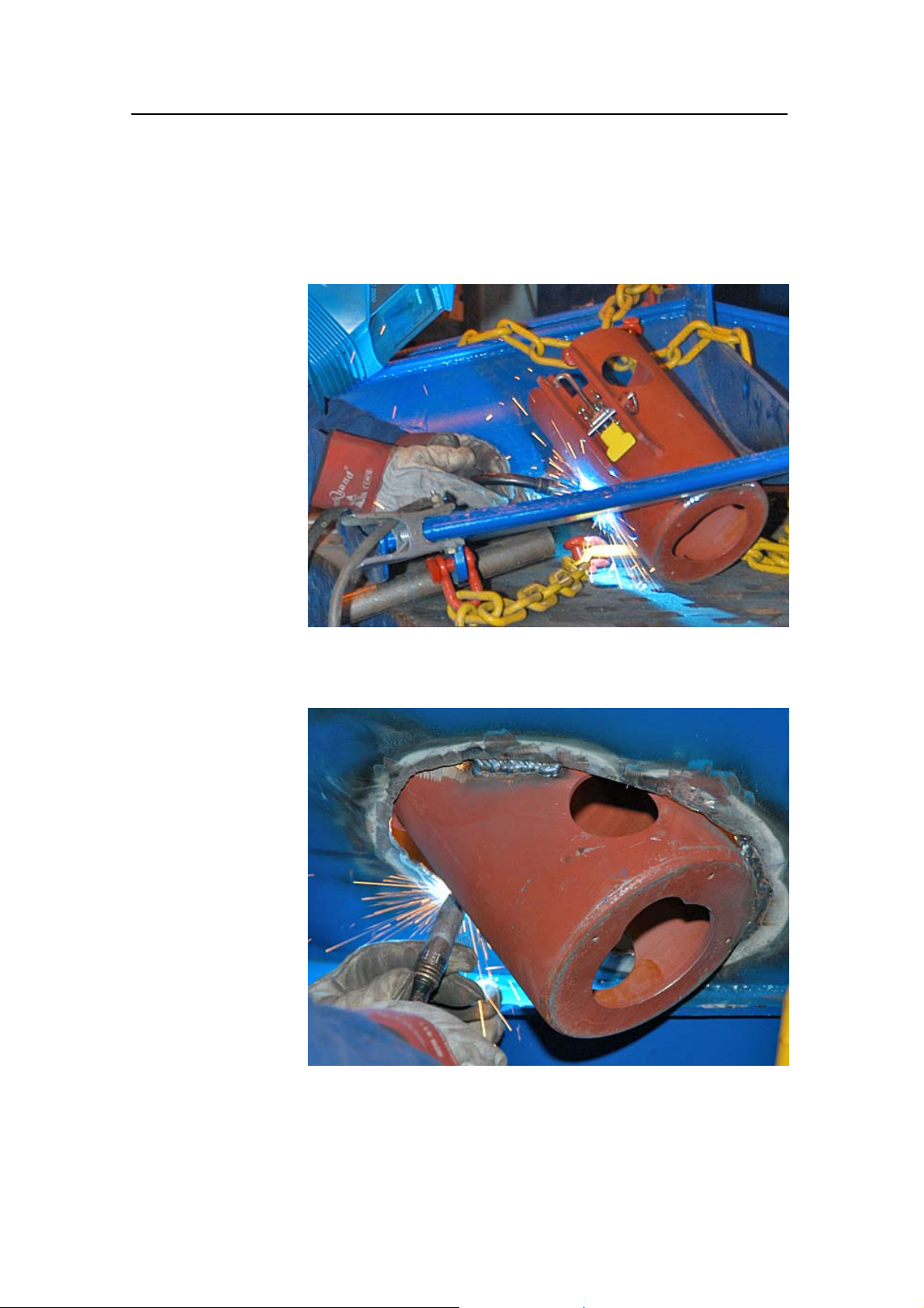
STEP 5: Weld the sensor adapters to the doors
Tack weld sensor adapters in position using the reference line
created in step 3 as a guide. Check that both angle and
orientation are in agreement with the drawings.
Permanently weld the sensor adapters to the doors using 7 to 10
cm long beads, it is not necessary to use a continuous weld.
10
857-164919 / Rev.B
Page 13

Installation manual
STEP 6: Measure the dimensions of the protective
cage legs
Using a yardstick bent at a ninety degree angle, measure the
length of standard 20 mm diameter bar stock necessary for the
apex of the protective cage to rise approximately 10 to 20 mm
over the sensor adapters.
Note Mark the locations (on the doors) where the outboard protective
cage legs will be welded.
Cut and bent the bar stock accordingly.
857-164919 / Rev.B
11
Page 14
Simrad PI Sensor adapter installation
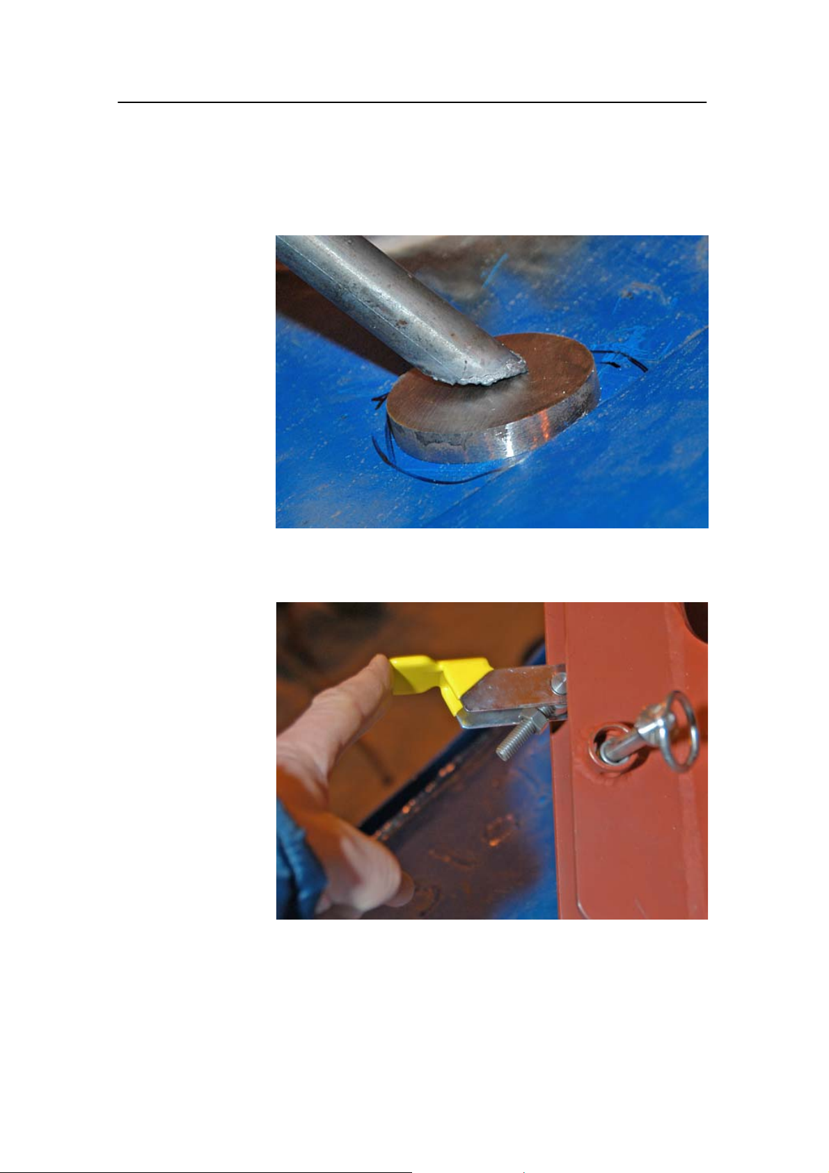
STEP 7: Attaching the doubling plates
Place the appropriately sized doubling plates on the locations
marked in step 6.
Temporarily holding the protective cage leg in place, check that
the release mechanism operates freely.
Note There must always be enough space between a protective cage
and its respective sensor adapter so that in the event it becomes
bent, the sensor may still be removed.
12
857-164919 / Rev.B
Page 15

Installation manual
STEP 8: Attach the outboard protective cage legs
Tack weld the protective cage legs to the doubling plates. Check
the alignment in relationship to the sensor adapter and its release
mechanism, adjust as necessary.
Weld the protective cage legs permanently in place.
857-164919 / Rev.B
13
Page 16

Simrad PI Sensor adapter installation
STEP 9: Attach the outboard protective cage
stiffener
Using a yardstick, and measure the length of standard 20 mm
diameter bar stock necessary to span from the apex of the
protective cage to the door.
Cut and weld the stiffener i n place.
14
857-164919 / Rev.B
Page 17

Installation manual
STEP 10: Fabricate and attach the inboard
protective cage legs and stiffeners
Proceed in the same manner as described in steps 6 through 9.
The protective cage is now ready for priming and painting.
857-164919 / Rev.B
15
Page 18

Page 19

Page 20

E 2005 Simrad AS
ISBN 82-8066-043-7
Simrad AS
Strandpromenaden 50
Box 111
N-3191 Horten
Telephone: +47 33 03 40 00
Facsim il e: +47 33 04 29 87
M A X I M I Z I N G Y O U R P E R F O R M A N C E A T S E A
 Loading...