

Page 1
QUICK REFERENCE GUIDE
PI Rip sensor
Purpose
The
PI Rip
sensor is identical to the
PI Catch
, and it must be regarded as a
second application for the Catch sensor.
The
PI Rip
sensor will monitor if your
net is damaged and ripped apart due to
obstructions or foreign objects on the
seabed.
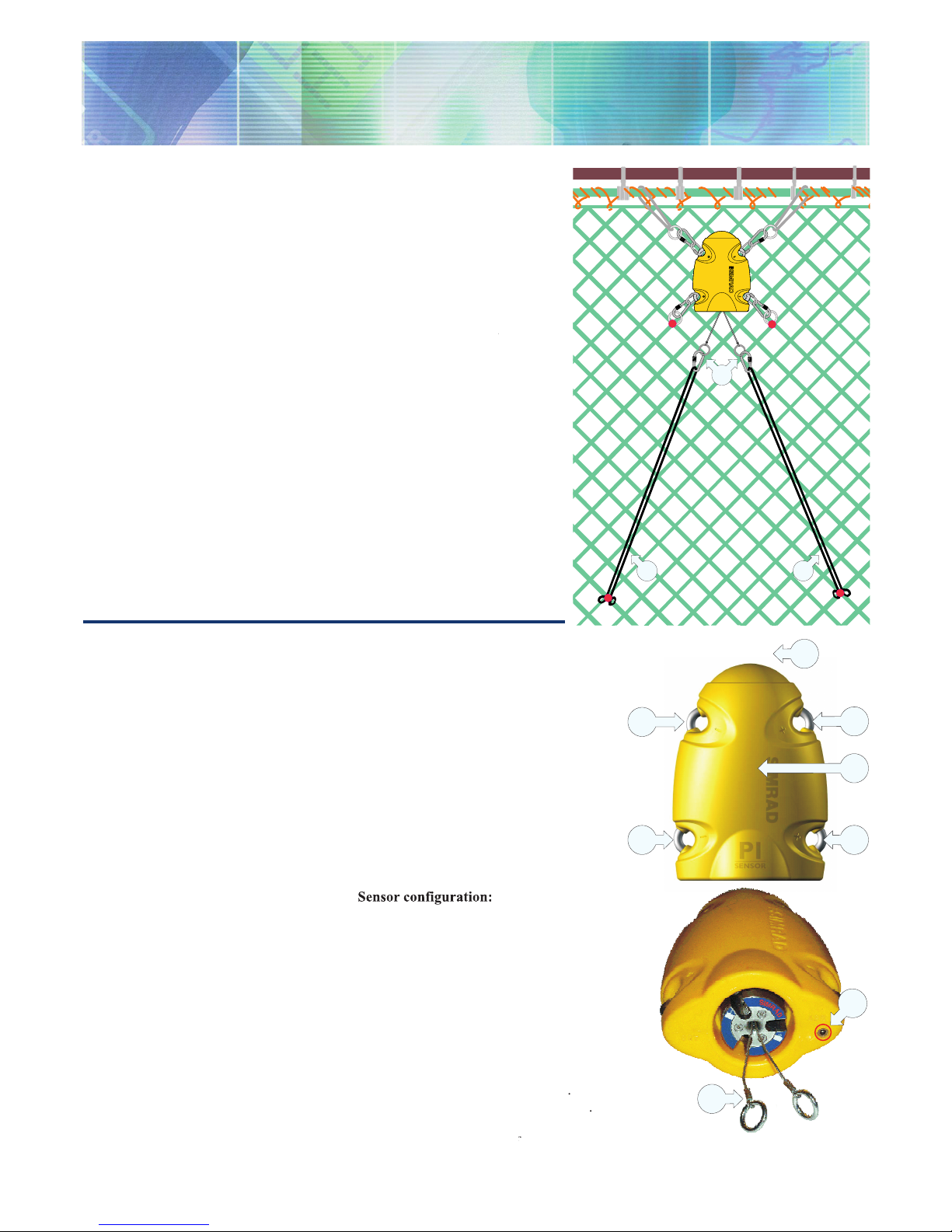
(A) = The PI Rip is mounted on the
footrope with the two sensor wires
stretched out and the wires engaged.
(B) = Two strong rubber bands
ensure that the sensor is activated.
If the net is torn, the slack in the net
will disengage the Rip sensor.
Daily operation
In most cases, one or two Rip sensors
mounted on the footrope will be
sufficient to monitor the condition of the
net. Once installed and put to use, the
sensor will automatically be switched on
once the waterswitch is activated. After
an initial startup, the sensor will detect
the status of the detection wires, and
transmit this information to the vessel.
When the sensor is not in use, check
that the sensor lamps (D) do not flash
from time to time, as this indicates that
the sensor is on and is discharging its
batteries. In this case, wash the sensor in
fresh water to remove salt and dirt.
Main parts
(A) = Negative charging / fastening lug
(B) = Positive charging / fastening lug
(C) = Communication link
(D) = Location of sensor lamp
(E) = Water switch sensor
(with sacrificial bolt)
(F) = Detection wires
Sensor confi guration
On delivery, all Rip sensors are
configured in
Channel 4
and with
Normal
update rate. If you wish to use
Rip
and
Catch
sensors simultanously, one of them
must be set to a different communication
channel.
Note: The sensor and the PI system
setup must correspond, otherwise the
communication will not work.
To change the sensor setup (channel
selection), use the PI Configurator utility.
The sensor update rate controls how
often the sensor reads and reports the
door spread. Three settings are available.
Note that a faster update rate will
decrease the battery life.
Fast
(~5,3 sec): Recommended if you
suspect that the bottom conditions are
rough and unpredictable, and that damage
may be easily inflicted. This mode
provides the shortest battery life before
charging.
Normal
(~33 sec): Recommended for
normal bottom conditions.
Slow
(~125 sec): Recommended if the
bottom conditions are well known, and
you know that no obstructions exist.
This mode provides longest operational
battery life before charging.
857-165111 / Rev.B / December 2005
(CD11206A)
B
B
A
A
A
B
C
B
D
F
(CD11206C)
E
)
)
System confi guration
Sensor configuration:
The sensor
must be configured with a unique
sensor number. Select channel number
and update rate according to the
sensor’s configuration. Write down the
configuration for future reference.
Status & Receiver
Level
if you have noise problems from other
hydroacoustic sources. Note that with
the filter on, it will influence the signal
Status display
Light
Heavy
only if you experience
will provide
raw data and fastest possible response.
Fast
update
rate, the sensor must be charged
with
Normal
Slow
update rates,
the operational life is approximately
Note: Charging sensors at sub-zero
temperatures can create explosive
gasses. Simrad assumes no liability
for the improper charging of
sensors or the use of chargers not
specified in Simrad sensor charging
documentation.
Page 2
M A X I M I Z I N G Y O U R P E R F O R M A N C E A T S E A
www.simrad.com
Numeric presentation
timer values exist, the timer characters are shown in grey.
replaced by the characters ***.* (in grey).
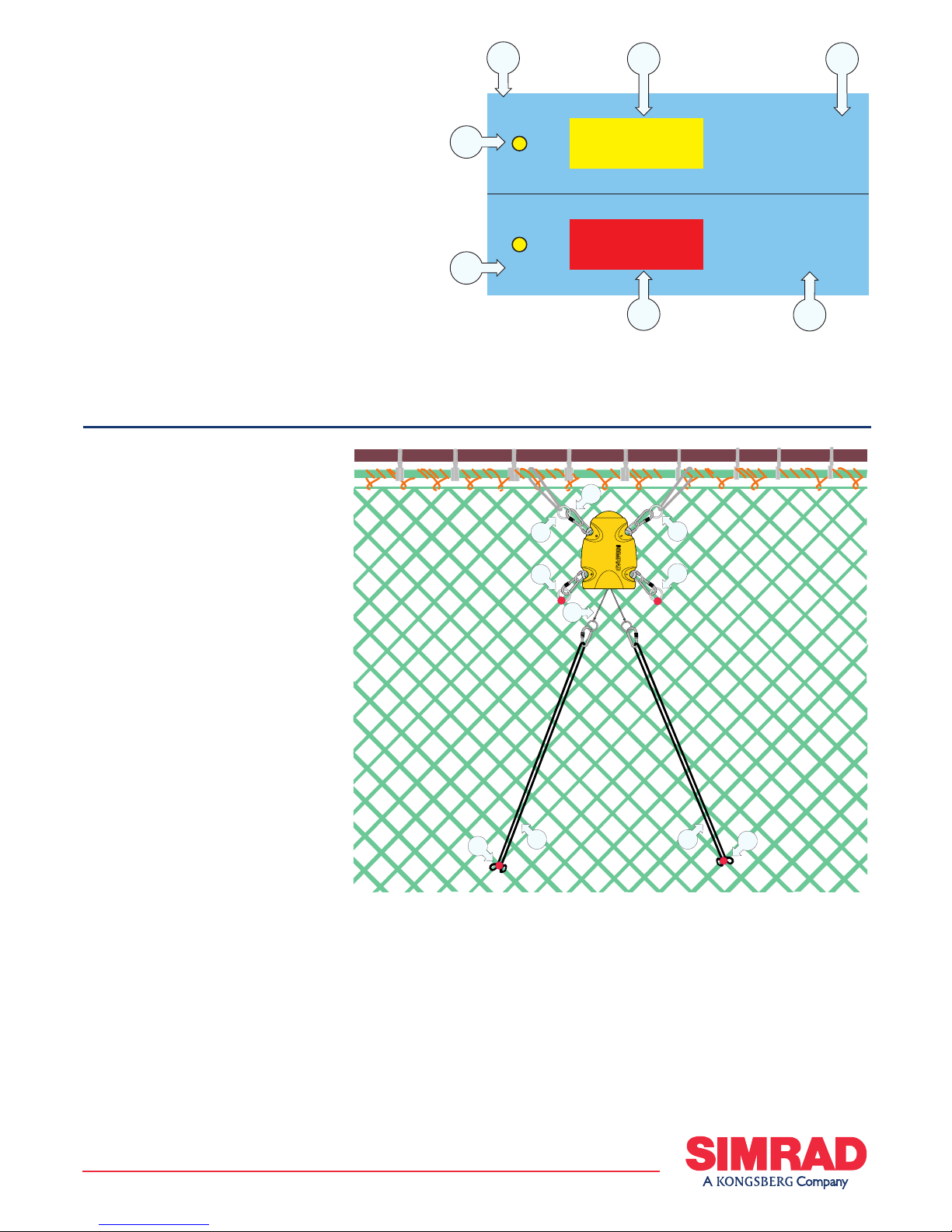
Mounting
Place the sensor where you
wish to check the net condition. This
Attachment:
The sensor’s orientation
towards the vessel is maintained by the
number of meshes the attachment rings
to avoid unnecessary stress on the sensors
will prevent the sensor from being lost.
Note that two steel rings must be mounted
on the same side of the sensor.
The two rubber bands
mounted to the meshes in such a way
that the detection wires are engaged
between the two rubber bands should be
rubber straps regularly and always before
visible signs of cracks or damage.
134
135
C3
C2
A
C
E
F
G
B
D
(CD11101S)
(CD11206B)
E
E
D
B
C
C
F
B
F
A
Rip sensor attachment to the net,
Sacrifi cial water switch
sensor
be checked every month. Whenever
required due to wear and tear, the screw
must be replaced. Refer to the operational
procedures in the operator manual.
 Loading...