

Page 1
QUICK REFERENCE GUIDE
PI Depth sensor
857-165107 / Rev.B / June 2005
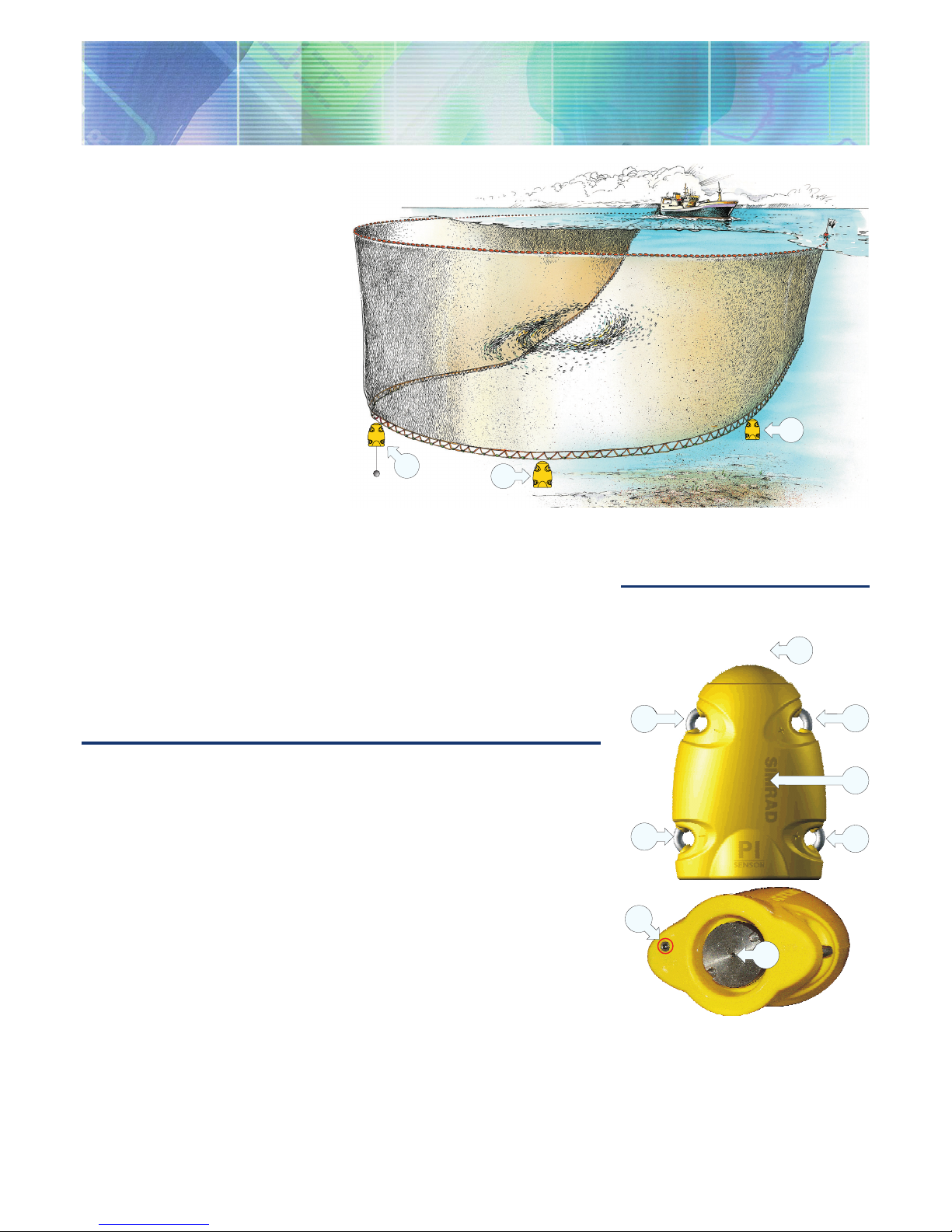
Purpose
The PI Depth sensor monitors the
current depth of the net, as well as the rate
of any depth changes. All measurements
are related to the surface.
A
A
B
(CD11201F)
(A) = Two Depth sensors are mounted to the ground rope to monitor the depth.
(B) = One Bottom Contact sensor is mounted to the ground rope to detect if the net hits
the bottom.
Daily operation
Once installed and put to use, the
sensor will automatically be switched
on once the waterswitch is activated.
After an initial startup, the sensor starts
transmission of the current depth when
this exceeds a predefined depth you
have selected. When the sensor is not
in use, check that the sensor lamp (D)
is not flashing from time to time, as this
indicates that the sensor is on and is
discharging its batteries.
If you operate with Fast update rate, the
sensor must be charged approximately
every 24 hours. Used with Normal
or Slow update rates, the operational
life is approximately 75 or 150 hours
respectively. The optimal sensor charging
temperature is from +10 to +25°C.
Note that charging sensors at sub-zero
temperatures can create explosive gasses.
Simrad AS assumes no liability for the
improper charging of sensors or the use
of chargers not specified in Simrad’s
sensor charging documentation.
)
)
)
)
)
)
)
)
)
)
)
)
)
)
)
)
)
)
)
)
)
)
)
)
A
A
B
C
B
D
E
F
(CD11201H)
Main parts
(A) = Negative charging / fastening lug
(B) = Positive charging / fastening lug
(C) = Communication link
(D) = Location of sensor lamp
(E) = Water switch sensor
(F) = Pressure sensor (label is removed)
Sensor configuration
On delivery, all depth sensors are
configured in Channel 16 (300 m),
Channel 12 (600 m) or Channel 10 (1000
m) and with Fast update rate. If you use
more than one sensor, you must set them
up to operate in different channels.
Note: The sensor and the PI system
setup must correspond, otherwise the
communication will not work.
To change the sensor setup (channel
selection), use the PI Configurator utility.
The sensor update rate controls how
often the sensor reads and reports the
current depth. Three settings are available.
Note that a faster update rate will decrease
the battery life.
Fast (~4,5 sec): Recommended for purse
seine or trawl, allows immediate update
of critical depth information, and helps to
avoid damage to the purse seine or trawl.
Normal (~14 sec): Recommended for
trawl and normal fishing.
System configuration
Sensor configuration: The sensor
must be configured with a unique sensor
number. Select channel number according
to the sensor’s configuration. Write down
the configuration for future reference.
Status & Receiver: The Interference
filter must be switched on. Set it to level
9 if you have noise problems from other
hydroacoustic sources. Note that with
the filter on, it will influence the signal
spectrum shown in the Status display.
Sensor filter: Switch this filter to Light.
Set it to Heavy only if you experience
excessive noise. Position Off will provide
raw data and fastest possible response.
Slow (~34 sec): Recommended if
maximum operational battery life before
charging is required. The system will be
more sensitive to bad communication
conditions due to the slow data update.
Page 2
M A X I M I Z I N G Y O U R P E R F O R M A N C E A T S E A
www.simrad.com
(CD11009C)
A
D
D
E
F
G
H
B
B
C
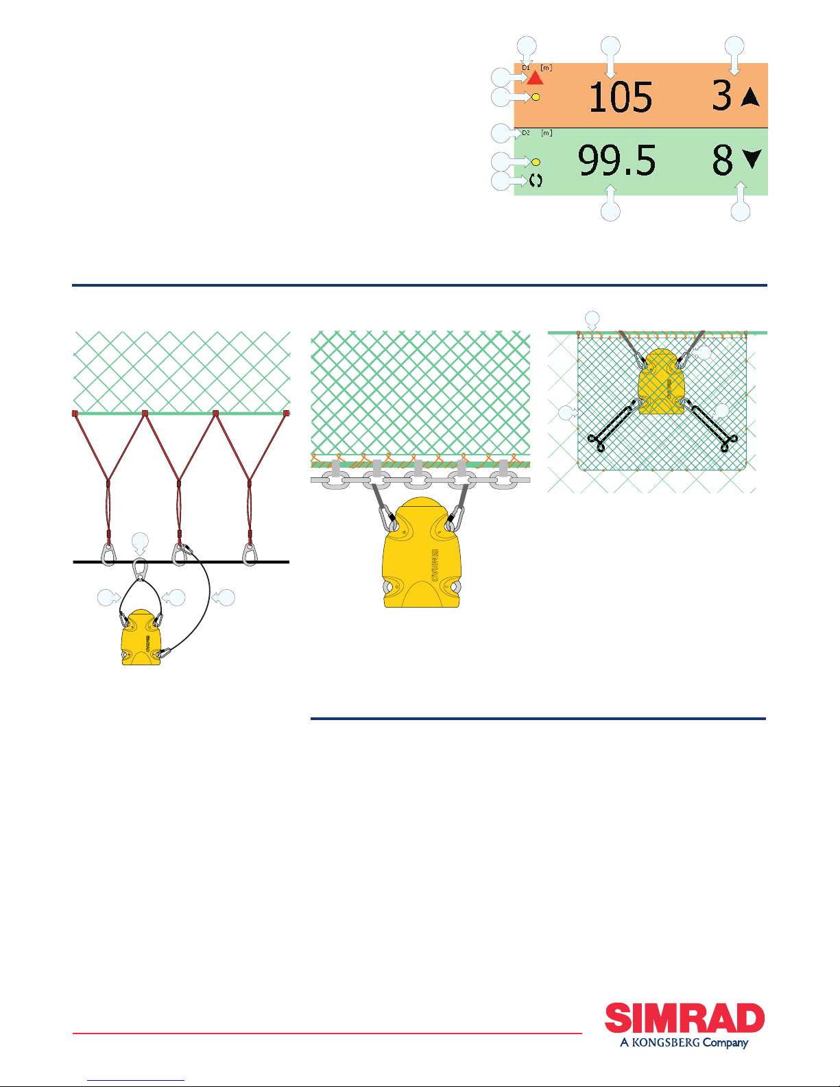
Depth presentation
On the PI display, the depth is displayed
in the numeric display. The descending
or ascending rate is shown in units per
minute supported by an arrow indicating
the direction. In order to monitor changes
of depth as a function of time, the depth
will also be displayed in the graphic
display showing both the numeric value
and a corresponding marker line for each
sensor. When the readings are stable,
the digits are shown in black colour.
When the values are predicted, the digits
are grey, and if the contact is lost, the
characters *.* * are shown in grey.
(A) = Sensor set up as sensor
no.1
(B) = Current depth
(C) = Current rate of depth
change. The arrow indicates that
the depth is ascending.
(D) = Indicator, lit for every
sensor interrogation
(E) = Graphic alarm
(F) = Sensor set up as sensor
no.2
(G) = Interference symbol
(H) = Current rate of depth change. The arrow
indicates that the depth is descending.
Purse seine: In order to secure stable
communication with the vessel’s
hydrophone, it is very important that the
sensor is allowed to hang freely with
the top end pointing towards the surface
during shooting and pursing.
Attach the sensor to a standard purse
ring with two separate wires (A). Mount
one end of each wire to a common snap
hook (B), and place another snap hook at
the other end of each wire to snap onto
the sensor.
Mount a safety line (C) between the
sensor and the adjacent bridle/purse ring.
Make sure that security line does not
prevent the sensor from hanging freely!
Remove the sensor from the purse seine
(CD11201A)
(CD11201I)
A A
C
B
Mounting
before it passes through the power block.
Any attachment material “permanently”
attached to the sensor’s charging lugs
must not form an electrical connection
between the two charging lugs shorting
the charging current.
(A) = Two wires with a snap hook in
one end and the other end attached
permanently to (B).
(B) = Large snap hook.
(C) = Safety wire with snap hooks on
each end. Note that the upper end is NOT
attached to the purse seine wire.
Tuna purse: The sensor must not be
attached to the footrope wire, but to the
foot-rope chain. Use a safety wire in
addition in case the sensor is ripped off
the net.
Trawl or Danish seine: The depth
sensor is normally attached to the
headrope (A). For secure fastening and
stable positioning of the sensor pointing
towards the vessel, make a fine mesh bag
(B) located at the centre of the headrope.
Size two snap hooks (C) approximately
10 - 15 cm from the headrope forming a
bridle, and keep the sensor stretched by
means of two rubber straps (D) attached
to the aft fastening lugs.
(CD11201L)
B
D
C
A
 Loading...