

Page 1
(CD11021C)
QUICK REFERENCE GUIDE
PI Catch sensor
Purpose
The
PI Catch
sensor detects when the
trawl has been filled with fish. The sensor
monitors the opening of the meshes in
the cod end, and will be activated once
the volume caught is enough to pull the
detector wires.
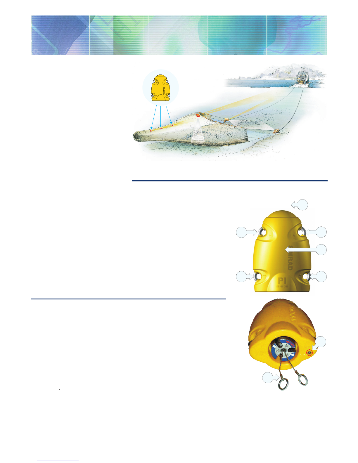
Catch sensor principle: Three sensors are mounted at the cod end of the trawl to detect
the amount of fish caught.
Daily operation
To monitor the filling rate, we
recommend that you use minimum two
sensors. The first sensor is located at the
far end of the cod-end indicating that the
trawl is fishing, while the second sensor
tells when to haul. Due to the fish moving
back and forth in the cod-end, the sensor
will normally change status (on/off)
several times until the volume caught
keeps the opening of the meshes stable.
Once installed and put to use, the
sensor will automatically be switched
on once the waterswitch is activated.
After an initial startup, the sensor starts
transmission of the detector wire (F)
status (in or out). When the sensor is not
in use, check that the sensor lamp (D)
is not flashing from time to time, as this
indicaties that the sensor is on and is
discharging its batteries.
If you operate with Fast update rate, the
sensor must be charged approximately
every 35 hours. Used with Normal
or Slow update rates, the operational
life is approximately 150 or 300 hours
respectively. The optimal sensor charging
Main parts
(A) = Negative charging / fastening lug
(B) = Positive charging / fastening lug
(C) = Communication link
(D) = Location of sensor lamp
(E) = Water switch sensor
(F) = Detection wires
temperature is from +10 to +25° C.
Note that charging sensors at sub-zero
temperatures can create explosive gasses.
Simrad AS assumes no liability for the
improper charging of sensors or the use
of chargers not specified in Simrad sensor
charging documentation.
Sensor confi guration
On delivery, all Catch sensors are
configured in
Channel 4
and with
Normal
update rate. If you use more than one
Catch sensor, make sure that you set them
up to operate on different channels and
with different sensor numbers!
Note: The sensor and the PI system
setup must correspond, otherwise the
communication will not work.
To change the sensor setup (channel
selection, update rate etc), use the
PI
Configurator
utility.
The Catch sensor can be configured
(using the PI Configurator software)
to act as a
FA701
catch sensor. This
will allow the sensor to be used
with the Simrad
FS
trawl sonar. The
communication channel on the FS sonar
must be set up to correspond to the
equivalent sensor number (1, 2 3 or 4).
The sensor update rate controls how
often the amount of fish caught is
measured and transmitted to the vessel.
Three settings are available. Note that a
faster update rate will decrease the battery
life.
Fast
(~5,3 sec): Recommended for
trawling in areas where the rate of filling
is very high. Use this setting to avoid
damage to the trawl or excessive catches.
Normal
(~33 sec): Recommended for
normal fishing.
Slow
(~125 sec): Recommended if
maximum operational battery life before
charging is required. The system will be
more sensitive to bad communication
conditions due to the slow data update.
When the Catch sensor is configured as
an FA701, it will have a constant update
rate of approximately 64 seconds. This
rate must not be changed.
857-165109 / Rev.A / February 2005
)
)
)
)
)
)
)
)
)
)
)
)
)
)
)
)
)
)
)
)
)
)
)
)
A
A
B
C
B
D
F
(CD11021D)
E
Page 2
M A X I M I Z I N G Y O U R P E R F O R M A N C E A T S E A
www.simrad.com
System confi guration
Sensor configuration:
The sensor
must be configured with a unique
sensor number. Select update rate
and channel number according to the
sensor’s configuration. Write down this
configuration for future reference.
Status & Receiver:
The Interference
filter must be switched on. Set it to level
9 if you have noise problems from other
hydroacoustic sources. Note that with
the filter on, it will influence the signal
spectrum shown in the Status display.
Catch/Bottom sensor filter:
Switch this
filter off. Set it to
Light
or
Heavy
only if
you experience excessive noise.
(CD11009B)
A
D
E
F
D
G
H
B
C
Catch presentation
On the PI display, the Catch
sensor status is displayed with
graphic symbols. The timers
count the total number of
minutes the sensor has been
activated (red rectangle). If
only predicted timer values
exist, the timer characters are
shown in grey. If the sensor
communication is lost, the
graphic symbol is replaced by
the characters ***.* (in grey).
(A) = Sensor set up as sensor no.2.
(B) = Sensor in standby. The timer has
stopped.
(C) = The timer counts how many minutes
the sensor has been activated during a
tow. It must be reset manually.
(D) = Indicator, lit for every sensor
interrogation.
(E) = Interference symbol
(F) = Sensor set up as sensor no.3.
(G) = The sensor has been activated. The
timer starts. An audible alarm may be
enabled.
(H) = The timer shows how many minutes
the sensor has been activated.
(CD11021B)
C
C
A
B
B
F
E
D
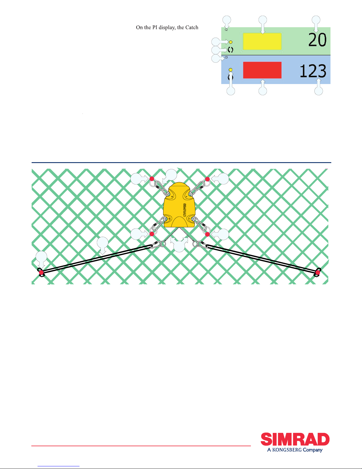
Mounting
Location:
Attach the sensor on top
of the cod-end where the catch is to be
monitored. As the cod-end fills, the net’s
meshes will open pulling the detector
wires activating the sensor.
Attachment:
The Catch sensor’s
orientation towards the vessel is
maintained by the steel and nylon
attachment rings. The number of meshes
the attachment rings are supported
between must be restricted to avoid
unnecessary stress on the sensors
fastening lugs when the cod-end is filled
to maximum. The use of both nylon
and steel attachment rings is required to
secure the sensor lugs if excessive forces
are applied on them. The nylon rings will
stretch or break down, but the steel ring
will prevent the sensor from being lost.
Sensor attachment to a net with an
approximate mesh size of 140 mm. The
distance between the anchor points for
the attachment rings and rubber straps
will vary according to mesh size and
sensitivity required.
(A) = Snap hook and screw link
(B) = Steel attachment rings bent to the
net
(C) = Nylon attachment rings bent to the
net
(D) = Detection wires
(E) = Rubber strap
(F) = Attachment point
Note that two steel rings must be mounted
on the same side.
Sensitivity:
The sensitivity of the Catch
sensor is determined by the number of
meshes separating the rubber straps. You
can simulate this by stretching the net’s
meshes to approximate the mesh opening
estimated to trigger the sensor. Mark the
location (with colored thread) for future
references.
Rubber straps:
Inspect the rubber straps
regularly and always before a new haul.
Replace them if you detect visible signs
of cracks or damage.
 Loading...