

Simrad PI BOTTOM CONTACT - QUICK REFERENCE GUIDE REV A, PI BOTTOM CONTACT Quick Reference Manual
Page 1
QUICK REFERENCE GUIDE
PI Bottom Contact sensor
857-165105 / Rev.A / February 2005
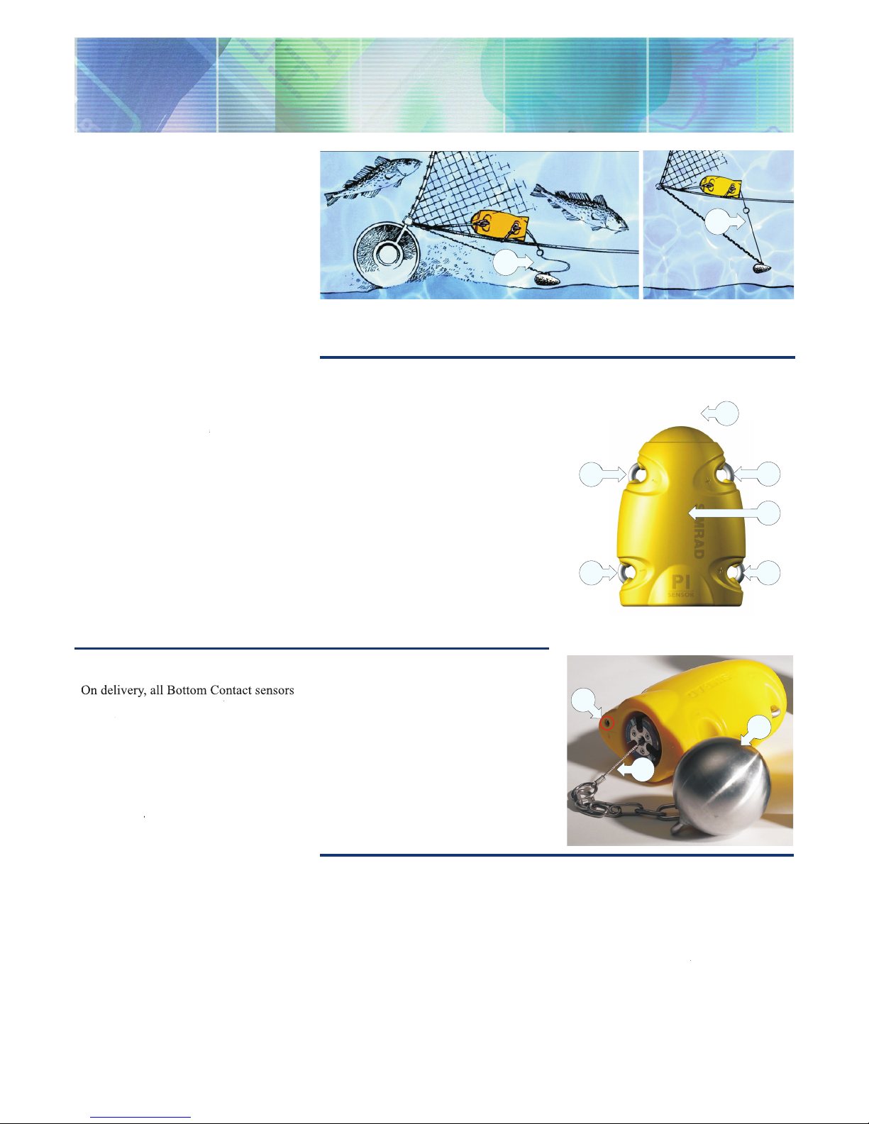
Purpose
The
PI Bottom Contact
sensor detects
if a trawl is accidentally lifted off the
seabed, or a purse seine is touching the
bottom.
Main parts
(A) = Negative charging / fastening lug
(B) = Positive charging / fastening lug
(C) = Communication link
(D) = Location of sensor lamp
(E) = Water switch sensor
(F) = Detection wire (in/out)
(G) = Ground weight
(A) = The trawl follows the bottom. The detection wire on the sensor is not released.
(B) = The trawl has lifted off the bottom, and the detection wire is released.
(CD11010A)
A
B
)
)
)
)
)
)
)
)
)
)
)
)
)
)
)
)
)
)
)
)
)
)
)
)
A
A
B
C
B
D
E
G
F
(CD11013B)
Sensor confi guration
On delivery, all Bottom Contact sensors
are configured in
Channel 6
and with
Normal
update rate.
Note: The sensor and the PI system
setup must correspond, otherwise the
communication will not work.
To change the sensor setup (channel
selection, update rate etc), use the
Configurator
utility.
The sensor update rate controls how
often the sensor monitors whether the
gear is on of off the bottom. Three
settings are available. Note that a faster
update rate will decrease the battery life.
Fast
(~3,2 sec): Recommended for
new trawl or gear, or changes in rigging
to monitor instabilities in ground gear
bottom contact.
Normal
(~5,3 sec): Recommended for
normal fishing.
Slow
(~33 sec): Recommended if
System confi guration
Sensor configuration:
The sensor must
be identified with a unique sensor number.
Select update rate and channel number
according to the sensor’s configuration.
Write down this configuration for future
reference.
Status & Receiver:
The
Interference
filter must be switched on. Set it to
level
maximum operational battery life before
charging is required. The system will be
more sensitive to bad communication
conditions due to the slow data update.
Daily operation
Once installed and put to use, the
sensor will automatically be switched
on once the waterswitch is activated.
After an initial startup, the sensor starts
transmission of the detector wire (F)
status (in or out). When the sensor is not
in use, check that the sensor lamp (D)
is not flashing from time to time, as this
indicaties that the sensor is on and is
discharging its batteries.
If you operate with
Fast
update rate, the
sensor must be charged approximately
every 26 hours. Used with
Normal
or
Slow
update rates, the operational
life is approximately 40 or 175 hours
respectively. The optimal sensor charging
temperature is from +10 to +25ºC.
Note that charging sensors at sub-zero
temperatures can create explosive gasses.
Simrad AS assumes no liability for the
improper charging of sensors or the use
of chargers not specified in Simrad sensor
charging documentation.
9
if you have noise problems from other
hydroacoustic sources. Note that with
the filter on, it will influence the signal
spectrum shown in the
Status
display.
Catch/Bottom sensor filter:
Switch this
filter off. Set it to
Light
or
Heavy
only if
you experience excessive noise.
Page 2
(CD11009)
A
D
E
F
D
G
H
B
C
M A X I M I Z I N G Y O U R P E R F O R M A N C E A T S E A
www.simrad.com
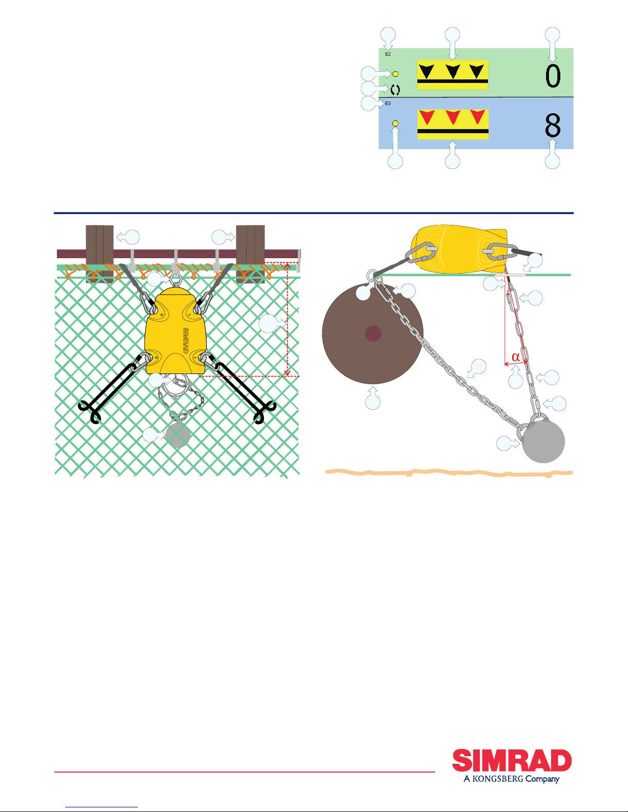
Mounting
Location:
Place the sensor where you
wish to monitor bottom contact. This is
normally in the center of the net. Seize
the attachment ring (A) for the stay
underneath the net, then put two snap
hooks inside the footrope forming a bridle
of 15 to 20 cm securely holding the sensor
in a stable position.
Penetration ring:
Place the
penetration ring (B) for the detection
wire approximately 30 cm rear of the
footrope. Before final seizing, mount the
sensor to the snap hooks and check that
the detection wire (E) passes trough the
center of the penetration ring (B). Remove
any net on the inside of the penetration
ring.
Set up:
Correct function requires that
Bottom Contact presentation
On the PI display, the Bottom Contact
sensor status is displayed with graphic
symbols. The timer count the total
number of minutes the sensor has lost
contact with bottom. If only predicted
timer values exist, the characters
are shown in grey. If the sensor
communication is lost, the graphic symbol
is replaced by the characters ***.* (in
grey).
(A) = Sensor set up as sensor no.2.
(B) = Sensor in contact with bottom. The
timer has stopped.
H
C C
B
A
(CD11010C)
30
cm
D
D
L
F
G
H
C
(CD11010F)
B
D
E
A
the length of the stay (F) and the detection
chain (G) are trimmed with regard to
each other and the gear in use. Standard
delivery includes a 63 cm stay and 39 cm
detection chain for use with 14 to 16 inch
bobbins or rock hoppers (C).
Adjustment:
Lay the sensor on an
elevated surface. Adjust the length of the
detection chain (G) as necessary. Observe
detection wire (E) movement while
simulating bottom contact by raising the
weight. Tilt the weight approximately
25º to compensate for drag forces when
towed through the water, and adjust the
stay length to be taut. To avoid damage,
remove the weight before coiling the gear
on the drum.
Note: The sensor’s detection wire must
always be allowed to pass freely through
the center of the penetration ring when it
is deployed. Attach the rubber straps so
that the sensor is held horizontally during
towing.
(C) = The timer counts how many
minutes the sensor has been ‘lifted
off’ the bottom. It must be reset
manually.
(D) = Indicator, lit for every
sensor interrogation.
(E) = Interference symbol.
(F) = Sensor set up as sensor
no.3.
(G) = Sensor has lost contact
with bottom. The timer starts. An
audible alarm may be enabled.
(H) = The timer shows how many
minutes the net has ‘lifted off’ during
a tow.
(A) = Attachment ring for the stay seized
securely underneath the footrope
(B) = Penetration ring for the detection
wire
(C) = Rock hopper, bobbins etc.
(D) = End link
(E) = Detection wire
(F) = Stay
(G) = Detection chain
(H) = Weight ~ 5.5 kg
(J) = Weight and stay hang freely.
(K) = Bottom
(L) = Angle approximately 25#
 Loading...