

Page 1
Operator manual
Simrad PI44
Catch monitoring system
www.simrad.com
M A X I M I Z I N G Y O U R P E R F O R M A N C E A T S E A
(CD11035E)
Page 2

Page 3

850-165085 / Rev.B
Simrad PI44
Catch monitoring system
Operator manual
Important notice
Operation of the PI44 catch monitoring system
assumes that the communication between the
Operator Unit and the sensors is fully functional.
Ensure that the communication channels and update
rates defined on the Operator Unit matches those of
the sensors.
Page 4

About this document
Rev Date Written by Checked by Approved by
Rev.B
02.12.05 RBr KR KR
Revised for SW version 0.40. New function Trawl Calculator implemented.
© 2005 Simrad AS
ISBN 82-8066-046-1
All rights reserved. No part of this work covered by the copyright hereon may be
reproduced or otherwise copied without prior permission from Simrad AS.
The information contained in this document is subject to change without prior notice.
Simrad AS shall not be liable for errors contained herein, or for incidental or consequential
damages in connection with the furnishing, performance, or use of this document.
The equipment to which this manual applies must only be used for the purpose for which
itwasdesigned.Improperuseormaintenancemay causedamagetotheequipmentorinjury
topersonnel. The usermustbefamiliar with the contentsof the appropriate manuals before
attempting to operate or work on the equipment. Simrad AS disclaims any responsibility
fordamageorinjurycausedbyimproperinstallation,useormaintenanceoftheequipment.
If you require maintenance on your Simrad equipment, contact your local dealer. You can
also contact Simrad using the following e-mail address: fish-support@simrad.com
Page 5

Sections
1Introduction
This section introduces the PI44 catch monitoring system operator manual.
Refer to page 1.
2 System description
This section provides a general introduction to the PI44 catch monitoring
system and the units in use. Refer to page 3.
3 Getting started
This section provides general guidelines to help you get started with the PI44
catch monitoring system. Refer to page 9.
4 Applications
This section gives an overview of the various applications that the PI44 can
offer. Refer to page 25.
Operator manual
5 Display modes
This section gives an in--depth description of all the display presentations.
Refer to page 32.
6 Operational procedures
This section provides detailed procedures to guide you through the most
common functions. Refer to page 55.
7 Practical use of the sensors
This section describes how to install and use each sensor type. Both PI and PS
sensors are described and explained. Refer to page 103.
8 Sensor chargers
This section describes how to install and use the sensor chargers.Refer to page
164.
9Menusystem
This section allows you to access the refer ence information from the menu
structure. Refer to page 169.
10 References
This section details the various setup pages, those selected from the menu
system and those accessed from the display presentation. Refer t o page 173.
11 PI Configurator
This section explains how to use the PI Configurator utility to change the
sensor’s communication channel and update r ate. Refer to page 226.
850-165085 / Rev.B
I
Page 6

Simrad PI44
12 Sensor test procedures
This section provides simple test procedureyou can use to verify thethe sensors
are working properly. Refer to page 265.
13 Technical specifications
This section provides the basic technical specifications. Refer to page 285.
14 Software updates
If you need to upgrade the software in your PI44 Operator Unit, the necessary
procedures can be found here. Refer to page 291.
II
850-165085 / Rev.B
Page 7

Operator manual
INTRODUCTION 1..............................................
SYSTEM DESCRIPTION 3......................................
System diagram 4..........................................
Operator Unit 5...........................................
Hull mounted and portable hydrophones 6......................
Sensor overview 7.........................................
Battery chargers 8..........................................
GETTING STARTED 9...........................................
How to switch power on and off 10.............................
Introducing the presentation principles 11........................
Defining initial presentation pages 13...........................
Introduction to the main menu 16..............................
Introduction to the keypad 17.................................
Introducing the sensors 20....................................
APPLICATION EXAMPLES 25....................................
Purse seine 26..............................................
Danish seine 27............................................
Bottom trawl 28............................................
Pelagic trawl 29............................................
Echo sounder 30............................................
Graphic display 31..........................................
DISPLAY PRESENTATIONS 32..................................
Numeric display 33.........................................
Graphic display 41..........................................
Surface temperature 45.......................................
Status display 46...........................................
Echo sounder display 50.....................................
Highway display 53.........................................
Position display 54..........................................
OPERATIONAL PROCEDURES 55................................
Overview 55...............................................
How to define sensor presentation 56...........................
How to set up the sensors 58..................................
How to mount the sensors on the net 61.........................
How to use the sensors 62....................................
How to replace the sacrificial water switch 63....................
How to test the sensors 64....................................
How to calibrate the Depth sensor 65...........................
850-165085 / Rev.B
III
Page 8

Simrad PI44
How to define sensor offsets 66................................
How to set up a Twin Spread sensor for twin trawl applications 67....
How to set up two Twin Spread sensors for dual twin trawl 72.......
How to access graphic display parameters 79.....................
How to view echo sounder data 80.............................
How to set up marker lines 81.................................
Special features for trawl marker lines 86........................
How to access echo sounder parameters 88.......................
How to use visual aids and filters 89............................
How to define echo sounder range 91...........................
How to zoom in on bottom echoes 93...........................
How to zoom in on pelagic echoes 94...........................
How to enable A-Scope presentation 95.........................
How to define alarm limits 96.................................
How to select menu language 99...............................
How to control automatic page rotation 100.......................
How to restore default settings 101..............................
How to personalize your system 102.............................
PRACTICAL USE OF THE SENSORS 103..........................
Sensor configuration 104......................................
PI Bottom Contact sensor 107..................................
PS Bottom Contact sensor 111.................................
PI Catch sensor 115..........................................
PS Catch sensor 120..........................................
PI Depth sensor 124..........................................
PS Depth sensor 129.........................................
PI Height sensor 134.........................................
PI Rip sensor 138............................................
PI Spread and Remote sensors 143..............................
PI Twin Spread 148..........................................
PI Temperature sensor 153.....................................
PS Temperature sensor 159....................................
SENSOR CHARGERS 164..........................................
Overview 164...............................................
PI Charger 165..............................................
PS30 Charger 167...........................................
MENU SYSTEM 169................................................
The main menu 170..........................................
Echo quick menu 172.........................................
IV
850-165085 / Rev.B
Page 9

Operator manual
REFERENCES 173..................................................
Setup map 174..............................................
Depth calibration 176.........................................
Echo presentation setup 177....................................
Echo sounder setup 180.......................................
Factory presets 183..........................................
Graphic setup 184...........................................
Interface setup 187...........................................
Marker line setup 197.........................................
Navigation setup 200.........................................
Numeric setup 202...........................................
Offset adjust 203............................................
Page setup 204..............................................
Palette setup 205............................................
Position display setup 206.....................................
Quick guide 207.............................................
Receiver setup 208...........................................
Sensor alarms 211...........................................
Sensor setup 215............................................
Speed setup 217.............................................
Status setup 218.............................................
Surface temperature setup 219..................................
Temperature setup 220........................................
Trawl calculator 221..........................................
Trawl info setup 223.........................................
Units setup 225..............................................
PI CONFIGURATOR 226..........................................
Purpose 226................................................
Basic information 227........................................
About sensor configuration 229.................................
Main dialogue description 231..................................
Operational procedures 233....................................
References 240..............................................
Maintenance 261............................................
SENSOR TEST PROCEDURES 265.................................
Overview 265...............................................
Bottom Contact test procedure 266..............................
Spread & Remote sensors test procedure 269......................
Catch sensor, test procedure 273................................
850-165085 / Rev.B
V
Page 10

Simrad PI44
Depth sensor, test procedure 276................................
Temperature sensor, test procedure 279...........................
Height sensor, test procedure 282...............................
TECHNICAL SPECIFICATIONS 285...............................
Sensors 286................................................
SOFTWARE UPDATES 291........................................
Overview 291...............................................
DSP Software upgrade 292....................................
MMI Software upgrade 296....................................
PI DSP Upload 299..........................................
INDEX 300.........................................................
VI
850-165085 / Rev.B
Page 11

Operator manual
Sensors
Use this table to write down the sensors you use on your PI44 catch monitoring system.
Sensor
type
Serial
number
Communication
channel
Update
rate
850-165085 / Rev.B
VII
Page 12

Simrad PI44
Sensors
Use this table to write down the sensors you use on your PI44 catch monitoring system.
Sensor
type
Serial
number
Communication
channel
Update
rate
VIII
850-165085 / Rev.B
Page 13

INTRODUCTION
The Simrad PI44 is an integration of proven commercial fishing
technologies which can dramatically increase the yield and
effectiveness of purse/danish seining and bottom/pelagic
trawling applications.
By means of six underwater sensors mounted on the gear, this
robust, maintenance-free catch monitoring system allows
unparalleled control over fishing operations by providing
continuous, centralised information on the vessel’s position, its
gear and the environment at and below the surface.
This manual is not intended to be read from cover to cover, but
is designed as a book of references that you can consult
whenever necessary.
This manual describes PI44 software version 0.40.
Introduction
Topics
→ System description, page 3
→ Getting started, page 9
→ Applications, page 25
→ Display modes, page 32
→ Operational procedures, page 55
→ Sensors, page 103
→ Menu system, page 169
→ References, page 173
→ PI Configurator, page 226
→ Sensor test procedures, page 265
→ Software updates, page 291
850-165085 / Rev.B
1
Page 14

Simrad PI44
Changes to this manual
The following changes have been made to this manual.
Rev.A
This was the original issue.
Rev.B
Operational procedures: Additional procedures added.
Sensors: “PI Twin Spread” and “Sensor configuration” chapters
added.
Software update: This is a new section.
New software version: SW 0.40 implemented. New function
“Trawl calculator” described.
2
850-165085 / Rev.B
Page 15

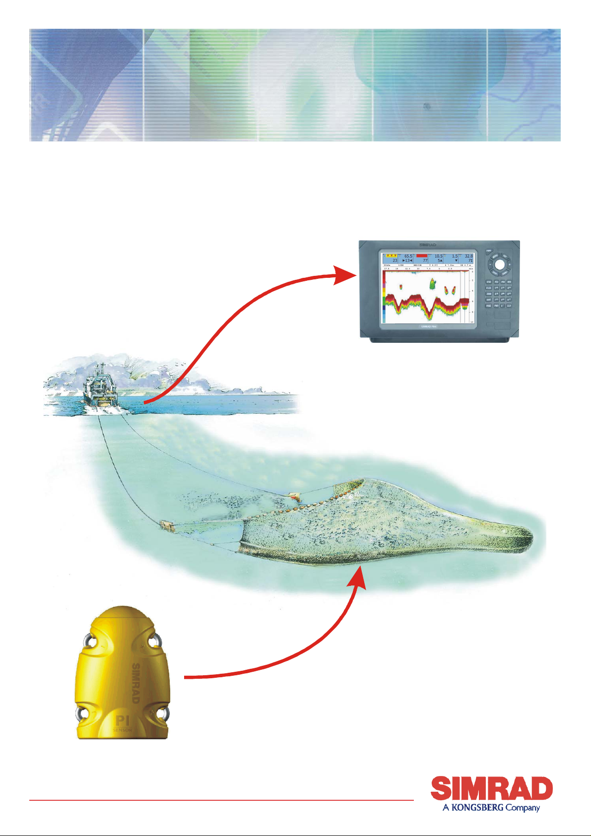
SYSTEM DESCRIPTION
The Simrad PI44 catch monitoring system consists of an
operator station, a hydrophone and an optional echo sounder
transducer. The hydrophone and the transducer are both
mounted under the vessel’s hull. The system further comprises a
number of small and robust sensors measuring the conditions on
your fishing gear.
The PI44 catch monitoring system can work with six sensors
simultanously.
The sensors are powered by built-in rechargeable batteries. They
are housed in titanium casings, and designed using advanced
shock absorbing materials. The information collected by the
sensors are sent through the water to the hydrophone by means
of coded sound waves. From the hydrophone, the signals are
sent to the operator unit, which decodes the information,
interprets it, and finally present it to you.
System description
Topics
→ System diagram, page 4
→ Operator unit, page 5
→ Hydrophones, page 6
→ Sensors overview, page 7
→ Battery chargers, page 8
850-165085 / Rev.B
3
Page 16
Simrad PI44
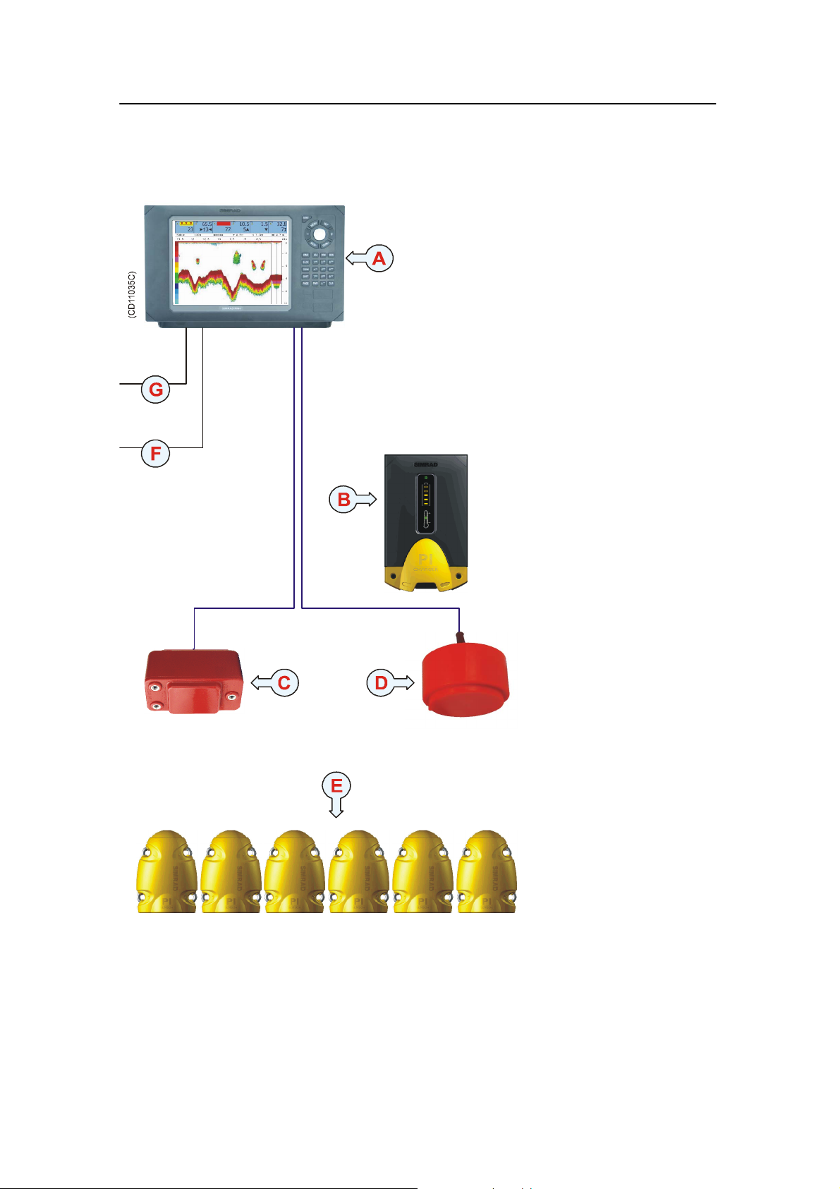
System diagram
(A) = Operator Unit
(B) = PI charger
(C) = Hydrophone
(provides communication
with the sensors)
(D) = Optional echo
sounder transducer.
Several types are
available.
(E) = Sensors mounted on
the net. Maximum six
sensors may be used
simultanously, and several
types are available.
(F) = Interfaces to
external sensors (serial
lines, NMEA format)
(G) = DC power input
4
850-165085 / Rev.B
Page 17
System description
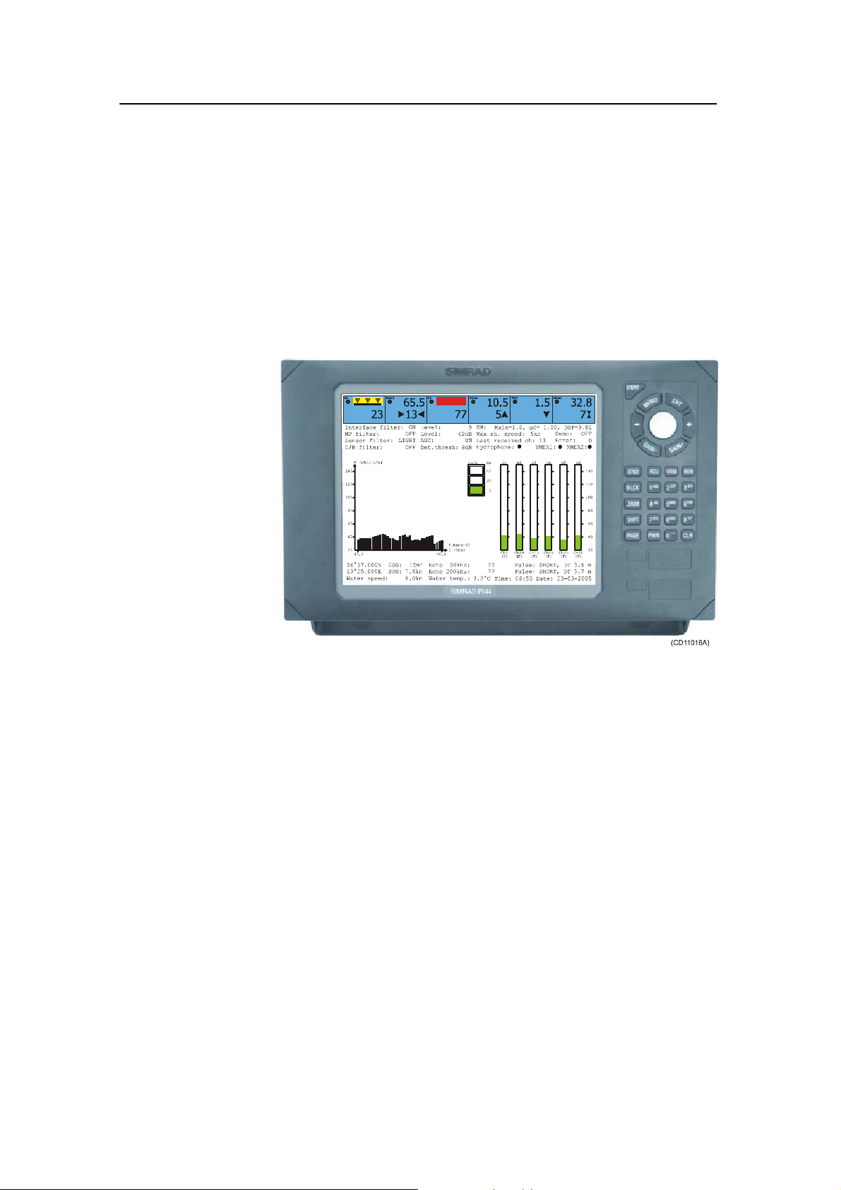
Operator Unit
The PI44 Operator Unit is a marine grade electronic
instrument incorporating an impact resistant polycarbonate front
panel, die-cast aluminium housing and watertight electrical
connections.
The PI44 electronics are sealed in the operator unit allowing the
it to be flush or bracket mounted in the wheelhouse or at an
exposed control station.
Computed information is displayed in both numerical and
graphical form on the display. The unit is operated using
drop-down menus and an integrated keypad.
850-165085 / Rev.B
5
Page 18
Simrad PI44
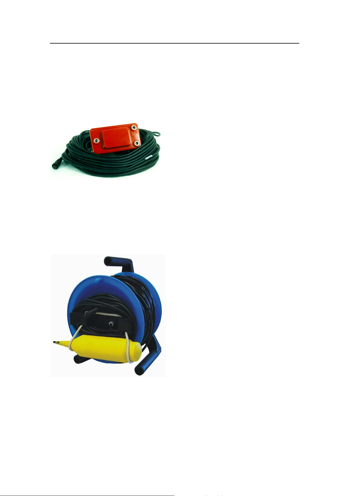
Hull mounted and portable hydrophones
Two hull mounted hydrophones are available, one for purse
seining operations, and one for trawl operations. You can install
both, and then select active hydrophone by means of a selector
box on the bulkhead.
Purse seining: The hull mounted
hydrophone for purse seining operations
has a 90 degrees horizontal beam and a
30 degrees vertical beam to provide the
PI44 with optimal reception from the
sensors. This specific beam pattern is
especially suited for purse seining and the
wide coverage area reduces the need for
careful alignment.
Trawling: The hull mounted hydrophone for trawling
operations has a 50 degrees horizontal beam and a 30degrees
vertical beam to provide the PI44 with optimal reception from
the sensors. This specific beam pattern is especially suited for
trawling and the wide coverage area reduces the need for careful
alignment.
(CD5582)
Portable: A portable hydrophone is also
available. It is designed as a temporary
measure until a fixed hydrophone can be
installed at the vessel’s next planned dry
docking. It has an omni-directional beam
and a 50 meter integrated cable which is
sheathed in polyurethane providing robust
external protection to compliment its 150
kg tensile strength. The cable is supplied on
a reel for convenient retrieval and stowage,
and is equipped with a plug for easy
attachment to the Operator Unit.
6
850-165085 / Rev.B
Page 19

System description
Sensor overview
This chapter provides a very short description of each sensor.
• Depth sensor - The Depth sensor provide information about
the current depth as well as the descending or ascending rate
related to the surface.
• Catch sensor - The Catch sensor provides information about
the amount of catch in the trawl. The sensor monitors the
opening of the meshes in the cod-end, and will activate once
the caught volume pulls the detector wire. To monitor the
filling rate, you are adviced to use minimum two sensors.
• Bottom Contact sensor - The Bottom Contact sensors
detects if a trawl is accidentally lifted off the seabed, or a
purse seine is touching the bottom.
• Rip sensor - The Rip sensor provides an immediate warning
when the net is ripped.
• Temperature sensor - Temperature sensors read and transmit
the ambient water temperature at the gear depth.
• Height sensor - The Height sensor contains s small echo
sounder to measure the current depth related to the seabed.
• Spread & Remote sensor - These sensor always work in
pairs, and they measure the distance betwen the trawl doors.
You can also use two Remote sensors if you run a twin trawl.
The use of separate communication channels for the individual
sensors allows you to use your sensors in the vincinity of other
vessels using PI or PS sensors. The communication channels can
be defined and/or changed onboard your vessel using a standard
computer and the PI Configurator utility.
Related topics
→ More information about the sensors, page 20
→ How to use the sensors, page 103
850-165085 / Rev.B
7
Page 20
Simrad PI44
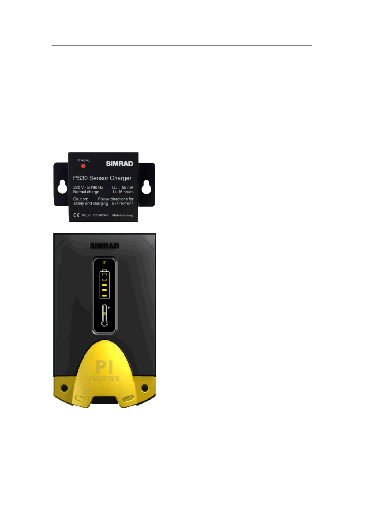
Battery chargers
All sensors are power by internal batteries, and these need
charging at regular intervals. The Simrad chargers have been
designed to allow the sensors to be stored in charging positions
whenever they are not used, and “overcharging” will not take
place. Either of the two charger types can be used on any of the
sensors, but the PI Charger will only provide fast charging on
the PI Sensors.
PS30 Charger
Three different Simrad PS30 Chargers are
available depending on the vessel’s main power
supply; 230 Vac, 110 Vac and +24 Vdc.
PI Charger
The PI Charger will provide fast charging of the
new PI sensor series. The Simrad PI Charger
requires a +12 to +32 Vdc power supply.
Related topics
→ PI Charger, page 165
→ PS30 Charger, page 167
8
850-165085 / Rev.B
Page 21

GETTING STARTED
This section contains an brief overview of the basic system
operation. If you are a first time user, we recommend that you
read through this chapter while operating the PI44 so that you
can familiarize yourself with the buttons, menus and display
presentations.
In order to navigate the menu structures and display
presentations, you need to know the most important buttons.
MENU: Press to access the main menu. Press again to close it.
ENT: Press to apply the changes you have requested.
Selector pad (circular): Press along the edges to move the
cursor.
PAGE: Leaf through the predefined display pages. Each page
can contain one, two or four separate windows. You can have
four different presentation pages active simultanously, and use
this button to access them.
Getting started
WIN: Press to select active window on the current presentation
page. Each page can have one, two or four windows. The active
window is identified with a red border.
ADJ: Press to access the setup parameters for the current
presentation.
Topics
→ How to switch power on and off, page 10
→ Introducing the presentation principles, page 11
→ Defining initial presentation pages, page 13
→ Introducing the main menu, page 16
→ Introducing the keypad, page 17
→ Introducing the sensors, page 20
850-165085 / Rev.B
9
Page 22

Simrad PI44
How to switch power on and off
Observe the following procedure to switch the PI44 on and off.
Power on
1 Press and hold the PWR button until the display is
switched on.
2 Observe that the start-up page appears.
3 Press ENT to start normal operations.
If you press PAGE you will access the built-in “Quick guide”.
Once opened, use the two GAIN buttons to leaf through the
pages, and then MENU or ENT to exit. If you wish to access
the “Quick guide” later, you can find it on the Setup menu.
When you power up the PI44, it will automatically assume
operation using the most recent page mode.
Power off
1 Press the PWR buttontocalluptheLight and power
dialogue.
2 Press and hold the PWR button to switch off the PI44.
10
850-165085 / Rev.B
Page 23

Getting started
Introducing the presentation principles
Observe the following description and procedures to understand
how the presentation principles apply.
Pages and Windows
The PI44 display is set up with four different presentation
pages. You can leaf through these pages by pressing the PAGE
button in the lower left corner of the keypad.
Each page can be set up to display one, two or four windows.
Each of these windows can then be set up to present the
information of your choice.
When you set up a page to contain more than one window, you
can select the active window using the WIN button. The active
window is identified with a red border.
To set up a presentation page
This procedure explains how to set up a page using the main
menu and the WIN button.
1 Press the MENU button to open the main menu.
2 Observe the WIN symbol in the top right corner of the
display.
3 Press the WIN button one or more times to select how
many windows you wish to use on the presentation page,
and which window you wish to active.
- The blue fields in the WIN symbol symbolises the page
configuration.
- The information you choose to display during this
session will be placed in the corresponding window on
the current page.
4 Use the selector tab, and move the cursor to the Fishery
menu.
5 Select one of the options on the menu.
- If a menu option is shown with red print, it means that
the information can not be displayed with the currently
selected window size. Use the WIN buttontoselecta
new window size.
- You can also select the menu option using the
corresponding alphanumerical button. You might find
that easier to do!
850-165085 / Rev.B
6 Press the ENT button.
- The PI44 will return to the previous page, and the
information you chose on the Fishery menu will
appear in the selected window.
11
Page 24

Simrad PI44
If you change your page configuration from full screen (one
window) to two or four windows, you may see that one or more
windows will not display any information. If this is the case,
observe the procedure below.
To define window information
This procedure explains how to set up the information in a
window using the WIN button and the main menu.
1 If your current page contains more than one window, press
the WIN button to select active window.
- The active window is identified by its red border.
2 Press the MENU button to open the main menu.
3 Use the selector tab, and move the cursor to the Fishery
menu.
4 Select one of the options on the menu.
- If a menu option is shown with red print, it means that
the information can not be displayed with the currently
selected window size. Select an other presentation.
- You can also select the menu option using the
corresponding alphanumerical button. You might find
that easier to do!
5 Press the ENT button.
- The PI44 will return to the previous page, and the
information you chose on the Fishery menu will
appear in the selected window.
Window sizes and information
Observe the table below to see which modes that can be used in
each window size.
Window size FULL HALF QUARTER
Numeric display -- Yes Yes
Graphic display Yes Yes Yes
Surface temperature Yes -- Yes
Status display Yes -- --
Echo display Yes Ye s Ye s
Pilot display Yes -- Yes
12
850-165085 / Rev.B
Page 25

Getting started
Defining initial presentation pages
Observe the following procedure to set up the four display pages
on the PI44. The presentations chosen are those commonly used,
but using the guidelines in this procedure you can change the
content of individual pages to suit your requirements.
Note that although the procedure instructs you to use the
Selector pad to make the menu selections, you may find it
much easier to access the choices directly using the
alphanumerical buttons.
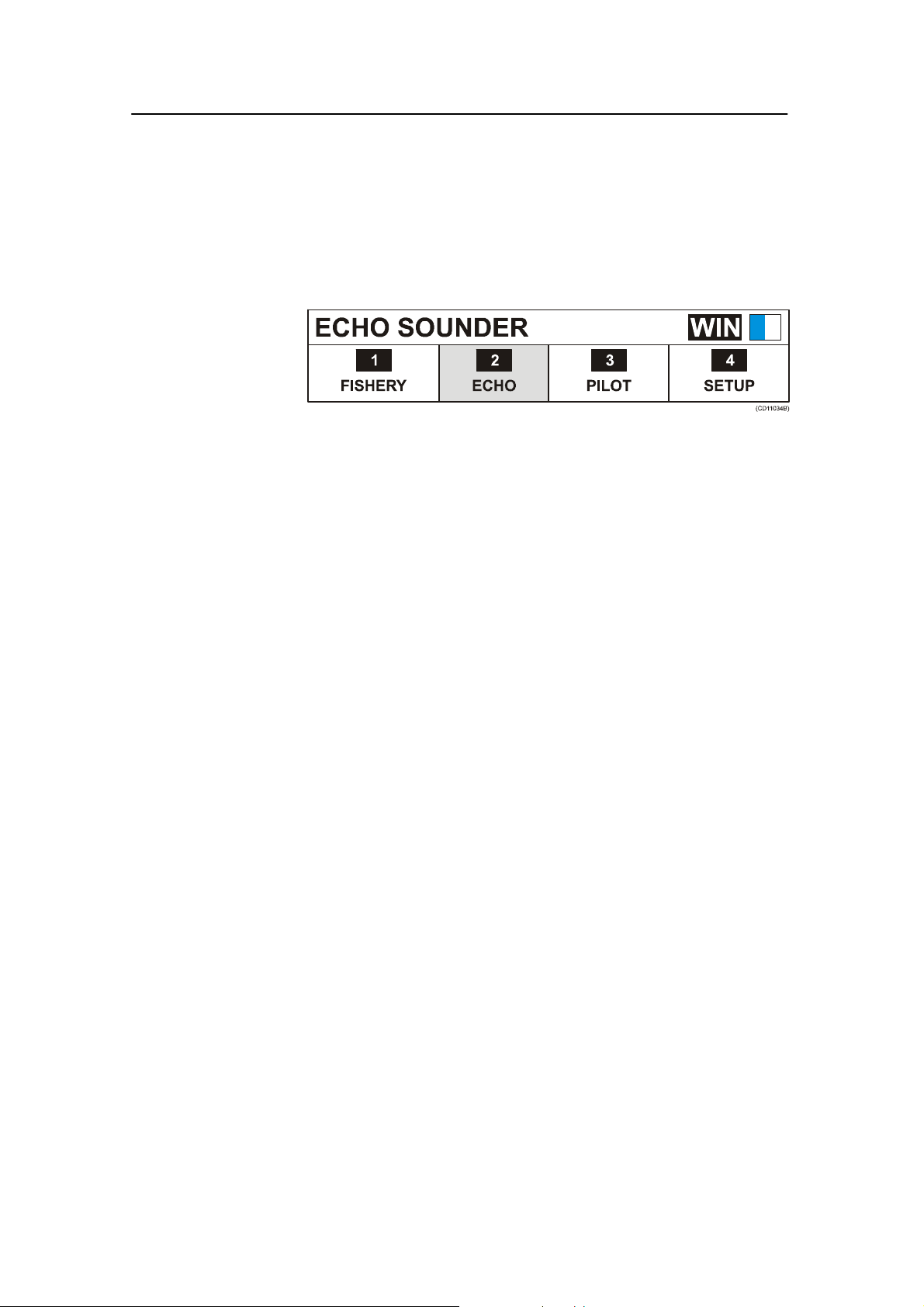
Page 1: Echo sounder
1 Press the MENU button to bring up the main menu.
2 Press the Selector pad to move the cursor (inverse video)
to the ECHO choice on the main menu.
3 Observe the WIN icon at the top right corner of the
display. Press the WIN button repeatidly until the blue
rectangle covers the entire icon.
4 On the Echo menu, select Echo 38 kHz.
5 Press the ENT button to enter the choice.
A full screen echo sounder appears. If you already know the
basic settings of an echo sounder you can access the Echo quick
menu by pressing the ENT button one more time.
Page 2: Numeric display
1 Press the PAGE button once to select the next display
page.
2 Press the MENU button to bring up the main menu.
3 Press the Selector pad to move the cursor (inverse video)
to the Fishery choice on the main menu.
4 Observe the WIN icon at the top right corner of the
display. Press the WIN button repeatidly until the blue
rectangle covers the left half of the icon.
5 On the Fishery menu, select Numeric display.
6 Press the ENT button to enter the choice.
850-165085 / Rev.B
The numeric display appears on the left (or right) half of the
display page. If you already know how to perform the basic
setup, you can access the Numeric setup by pressing the ADJ
button.
13
Page 26

Simrad PI44
The right side may have been predefined to provide an other
display presentation, or it may simply show the text Select
display via MENU. In order to fill the space,proceed as follows:
7 Press the WIN button, and observe the red border moving
from one window to the next. Place the border on the
window you wish to define.
8 Press the MENU button to access the main menu.
9 Press the Selector pad to move the cursor (inverse video)
to the Echo menu.
10 On the Echo menu, select Echo 200 kHz.
11 Press the ENT button to acknowledge.
The 200 kHz echo sounder will now appear in the chosen
window.
Page 3: Graphic display
1 Press the PAGE button once to select the next display
page.
2 Press the MENU button to bring up the main menu.
3 Press the Selector pad to move the cursor (inverse video)
to the FISHERY choice on the main menu.
4 Observe the WIN icon at the top right corner of the
display. Press the WIN button repeatidly until the blue
rectangle covers the entire icon.
5 On the Fishery menu, select Graphic display, Echo 38
kHz.
6 Press the ENT button to enter the choice.
The graphic display appears with the sensor data shown on the
top and the echo sounder shown below. If you already know
how to set up the basic parameters you can access the Echo
quick menu by pressing the ENT button one more time.
Page 4: Navigation display
1 Press the PAGE button once to select the next display
page.
14
2 Press the MENU button to bring up the main menu.
3 Press the Selector pad to move the cursor (inverse video)
to the PILOT choice on the main menu.
4 Observe the WIN icon at the top right corner of the
display. Press the WIN button repeatidly until the blue
rectangle covers the entire icon.
850-165085 / Rev.B
Page 27

Getting started
5 On the Pilot menu, select Highway.
6 Press the ENT button to enter the choice.
The navigation display appears. If you already know how to set
up the basic parameters you can access the Navigation setup
page by pressing the ADJ button.
Leafing through the pages
To leaf through the display presentations you have defined,
press the PAGE button.
Other display presentations
Several other display presentations are available, but you only
have four different display pages to use. After some experience
with the PI44 system, you will however soon find out which
display presentations that are the most useful to you, and you
can alter the setup accordingly.
Related topics
→ Display presentations, page 32
850-165085 / Rev.B
15
Page 28
Simrad PI44
Introduction to the main menu
The main menu is located across the top of the display. To open
the menu, press the MENU button. Note that if it is left
unactivated, the menu will disappear automatically after a few
seconds.
Each of the four options of the main menu provide a drop-down
menu. On these, you can select which information to view in
each display window, or which parameters to define. Main and
drop-down menus are highlighted when selected, and the
complete main menu title is displayed in the top left-hand corner
of the screen.
Observe the WIN icon in the top right corner. Using the WIN
button, you can position the information into the selected
window on the current page. Note however that setup pages are
not affected by the choices you make with the WIN button.
• To open a sub-menu, press the ENT button, press the
corresponding alphanumerical button, or press “down” on the
selector tab.
• To make your selection, highlight the choice and press the
ENT button. You can also press the corresponding
alphanumerical button.
Related topics
→ The choices on the main menu, page 170
16
850-165085 / Rev.B
Page 29

Getting started
Introduction to the keypad
The keypad is used for direct user interface with the PI44
system, and allows you to control the functionality. Note that the
majority of the buttons are mainly used only during echo
sounder operations, and that some of them will only work when
they are enabled by a specific function.
EVENT: This button places a vertical marker on the
echo sounder depth display to identify an event.
MENU: This button turns the menu bar on and off. It
will also allow you to exit dialogues without applying
any changes.
ENT (Enter): This button allows you to apply the
changes you have made in a setup dialogue, or to select
a function from the menu. This button will also give
you access to the “Echo quick menu”, and it will open
the setup dialogue for the presentation in the active
window.
Selector pad: Use this button to navigate through
menus and dialogues. It moves the cursor horizontally
by pressing it on the left or right side, and vertically by
pressing it on its top or bottom.
-/+: These two button are used to select between
available values, scales and ranges. (-) reduces and (+)
increases the graduation.
GAIN: The two gain buttons are used to adjust the
receiver gain on the echo sounder.
STND (Standard): This button will activate an echo sounder
window in Standard mode. If you press this button while an
other window is active, the display switches to an echo sounder
page. If one of your other pages already contains a full screen
echo sounder, the PI44 will automatically change to this page,
and you must press the PAGE button to return to your previous
page. If you do not have an echo sounder presentation among
your four presentation pages, the current presentation will be
replaced by the echo sounder presentation.
ADJ (Adjust): This button provides a direct access to the setup
parameters for the data in the active window. To exit the setup
without making changes, press the MENU button.
850-165085 / Rev.B
VRM (Variable Range Marker): This button provides a
horizontal marker line on the echo sounder display. Use the
selector pad to alter the depth of the marker. The button will
only work if you have an echo sounder presentation on the
current page.
17
Page 30

Simrad PI44
WIN (Windows): This button is used to select which display
window to be active. During normal operation, the active
window is identified with a red border. When the main menu is
opened, the current active window is shown in the upper right
corner of the display.
B-LCK (Bottom lock expansion): This button will activate an
echo sounder window, and then expand the area just above the
bottom. In the expanded view, the bottom will appear flat. The
vertical range of the expansion window is defined in the echo
sounder setup. If you press this button while an other window is
active, the display switches to an echo sounder page. If one of
your other pages already contains a full screen echo sounder, the
PI44 will automatically change to this page, and you must press
the PAGE button to return to your previous page. If you do not
have an echo sounder presentation among your four presentation
pages, the current presentation will be replaced by the echo
sounder presentation. To switch off this function, press the
STND or SHIFT buttons.
ZOOM: This button will activate an echo sounder window, and
then expand an area above and below a horizontal marker line.
The depth of the marker line can be adjusted with the selector
pad, while the vertical range of the expansion window is defined
in the echo sounder setup. If you press this button while an other
window is active, the display switches to an echo sounder page.
If one of your other pages already contains a full screen echo
sounder, the PI44 will automatically change to this page, and
you must press the PAGE button to return to your previous
page. If you do not have an echo sounder presentation among
your four presentation pages, the current presentation will be
replaced by the echo sounder presentation. To switch off htis
function, press the STND or SHIFT button.
SHIFT: This button will activate the Phased range echo
sounder mode. You can then select start range with the + and buttons, and depth range with the numerical buttons (1 to 9). If
you press this button while an other window is active, the
display switches to an echo sounder page. If one of your other
pages already contains a full screen echo sounder, the PI44 will
automatically change to this page, and you must press the
PAGE button to return to your previous page. If you do not
have an echo sounder presentation among your four presentation
pages, the current presentation will be replaced by the echo
sounder presentation. T o select Standard mode, press the
STND button.
18
850-165085 / Rev.B
Page 31

Getting started
PAGE: The page button is used to leaf through the predefined
presentation pages. If you press and hold this button for more
than three seconds, you will start automatic page rotation. The
PI44 will then leaf through the four pages automatically. The
page rotation interval (time used to display each page) is
controlled by page setup parameter. To switch this function off,
press any other button.
PWR (Power): This button is used to switch the system on and
off. During operation, it is also used to adjust the display
brightness and contrast.
CLR (Clear): T his button will remove the variable range
marker. It will also clear the input fields in dialogues.
0to9:The alphanumerical buttons will greatly speed up your
menu operations, as you can access most menu items using a
number. You can also use these buttons to insert data into
dialogue fields. During echo sounder operations, they will even
provide you with fast access to a set of predefined depth ranges.
The 0 button will enable automatic depth range selection.
850-165085 / Rev.B
19
Page 32

Simrad PI44
Introducing the sensors
The PI44 catch monitoring can be used with a variety of
sensors. All these sensors can be placed on your trawl or purse
seine to monitor key parameters.
On the PI44, you can use maximum six sensors simultanously.
There are two sensor families; PI and PS. The sensors in the
two families are almost identical, and they can be used together
on the same PI44 system. The PI sensors will however offer
increased range, some added functionality, and they can also be
charged much faster using the PI Charger.
Bottom Contact: Best at the bottom!
With patented technology and awardwinning design, Simrad
provides you full control of the actions that take place at the
bottom. Mounted on a bottom trawl, pelagic trawl or purse
seine, this sensor will provide the important information when
you need it!
20
(A) = The Bottom Contact sensor mounted on a bottom trawl
will let you know once the trawl lifts a few centimeters above the
bottom. You can then immediatley perform the necessary
adjustments, and you will not loose any catch.
(B) = On a purse seine you will be notified once the seine
reaches the bottom, and you can thus fish even on a rough
bottom.
(C) = On a pelagic trawl, the sensor will notify you once you get
near the bottom.
The Bottom Contact sensor will let you know immediately if
your gear touches the bottom.
• Bottow trawl: If your trawl lifts off the bottom, this may
cause fish to escape, and hence reduce the catch. This sensor
will detect this, and allow you to trim your equipment for
perfect balance.
850-165085 / Rev.B
Page 33

Getting started
• Pelagic trawl: On a pelagic trawl, this sensor proves very
useful when the trawl moves downwards. It will let you
know immediately if the footrope touches bottom.
• Purse seine: When you work with a purse seine, you need to
know when the seine reaches the bottom. This sensor will let
you know. once it happens.
• Danish seine: Used on a Danish seine, the sensor will let you
know when the net has a stable bottom contact, and when it
is time to haul.
• Scientific research: During scientific surveys, an exact
definition of towed distance with proper ground gear contact
is an essential parameter in bottom trawl swept area estimates
of fish abundance. Using a Bottom Contact sensor will
reduce errors in this key parameter.
Catch sensor: When is the trawl full?
This is your “eye” at the cod-end. With PI Catch sensors in use,
you can easily monitor the fi lling rate and the amount of catch
in the trawl. Save time and fuel, haul in the trawl at the right
moment! The design is rugged and awardwinning, and the
sensor’s sensitivity is easily adjustable for trawls of all sizes.
Some professionals claim that the Catch sensor is the most
important sensor on the trawl. Why? Because it will tell you the
amount of catch in the trawl.
The sensor simply monitors the expansion of the meshes in the
cod-end. Once the volume caught is enough to expand the
meshes, they will pull the detector wires and engage the sensor.
The sensitivity of the sensor can easily be adjusted, just extend
the detection rubber bands to span additional meshes.
To monitor the filling rate, we recommend that you use
minimum two sensors. Place the first sensor at the far end of the
cod-end, it will tell you that the trawl is actually fishing. Place
the second sensor closer to the trawl opening. Once the trawl is
filled to the chosen location, the sensor is engaged, and you
know that it is time to haul.
850-165085 / Rev.B
Use the PI Catch sensor to adjust the catch volume according to
the production capacity, check that the trawl is fishing, adjust
the caught volume to secure quality, and minimize the towing
time to save fuel. These are only a few of the reasons why this
sensor is considered to be so important.
21
Page 34

Simrad PI44
Depth: How deep can you go?
When the sonar and echo sounder tell you how deep the school
goes, it is good to know that you can place your fishing gear at
the same depth. And even better, you can monitor and hold the
desired depth. The design is rugged and awardwinning, and the
sensor is available for three different depth ranges.
The PI Depth sensor provides information about the current
depth and the depth changes of your gear.
• Bottom trawl: On a bottom trawl, you will use the sensor to
achieve full control when shooting, and to position the trawl
on the slope.
• Pelagic trawl: During pelagic trawling, you know how
important it is to position the trawl relative to the largest
concentration of fish. By using a Depth sensor, you can
monitor the exact depth relative to the surface, and adjust the
trawl depth accordingly. Additional depth sensors on the
doors will monitor if the doors stay at the same depth.
• Purse seine: During seining, use the Depth sensor to monitor
the depth of the net, and the descending speed of the net.
Then you will know when to start pursing, and which speed
to use.
• Danish seine: Mounted on a Danish Seine the Depth sensor
monitors the sinking speed of the net, and it will tell you
when to start hauling once the net has stopped sinking.
Height sensor: Accurate distance to the bottom!
With a built-in echo sounder, this new PI sensor is full of
advanced technology. Wherever you place it, it will always tell
you the exact distance to the bottom.
The height sensor measures the height over the bottom, that is
the distance from the bottom and up to wherever the sensor is
located. This provides you with a valuable range of applications
for bottom and pelagic trawling.
• Bottom trawl: Place the sensor behind the headrope, and it
will tell you the height of the trawl opening. This allows you
to adjust you equipment immediately if the opening is
reduced, and you will avoid loosing catch.
22
• Pelagic trawl: With a height sensor behind the footrope you
will know at once if the trawl approaches the bottom. If you
use a second sensor behind the headrope, the difference
between the two measurements will give you the height of
the trawl opening.
850-165085 / Rev.B
Page 35

Getting started
Rip: Check for damages!
The Rip sensor is identical to the Catch sensor, and can thus be
regarded as a application for the Catch sensor. Place the sensor
on the trawl belly behind the footrope, and use it to detect if the
trawl is torn or in any other ways damaged by rocks or other
roughness on the bottom. If this is detected immediately you can
adjust the gear to minimise the damage.
Spread and Remote: Check the trawl doors!
This dynamic duo tells you the exact distance between the trawl
doors. Used on bottom and pelagic trawls the Spread and
Remote sensors provide crucial information about your trawl
behaviour. On a twin trawl, simply add a Remote sensor and
you have both openings covered!
These two sensors always work in pairs. They are used to
monitor the physical distance between the trawl doors during
bottom and pelagic trawling.
Use a Spread sensor on the port door and a Remote sensor on
the starboard door. Both sensors are normally mounted in
special adapters, but you may also attached them to the
wing-end or warp using snap hooks or rope.
The Spread sensor communicates with the Remote sensor using
a special transverse communication link. By means of this link it
measures the excact distance (maximum 350 meters) between
the two sensors. The information is is transmitted to the vessel
by the Spread sensor.
As you already know, correct door spread is important in order
to obtain the correct sweep-angle, as this ensures optimal trawl
performance. Door behavior and stability during shooting and
towing is also monitored by these sensors. Many regard this pair
of sensors one of the most important sensors to obtain efficient
trawling.
A special version of the PI Spread sensor, The PI Twin Spread,
allows you to use a single Spread sensor with two Remote
sensors to monitor a twin trawl.
Temperature: Too warm or too cold water?
Fishingintoowarmortoocoldwatermaybejustawasteof
time and money. The same applies to a pelagic trawl placed on
the wrong side of a thermal layer. Using advanced technology,
rugged construction and awardwinning design, the PI
Temperature sensor allows you to increase your fishing
efficiency.
850-165085 / Rev.B
The PI Temperature sensor tells you the exact sea water
temperature while you are fishing.
23
Page 36

Simrad PI44
The water temperature is an important parameter. Fish and bait
are temperature sensitive, and they are normally found within
specific temperature zones for feeding and spawning.
However, the temperature layers in the water are changing
constantly, and for this reason the temperature must be
monitored constantly. Fishing in an area with unfavourable
water temperature might be just a waste of time!
For any kind of trawling, use this sensor to monitoring and log
the temperature. Then, increase your knowledge about the
correlation between temperature, fish concentration and catch
efficiency. On a purse seine net, monitor the temperature to see
when you are passing the thermo-cline.
Related topics
→ Purse seine, application, page 26
→ Danish seine, application, page 27
→ Bottom trawl, application, page 28
→ Pelagic trawl, application, page 29
→ Sensor configuration, page 104
→ PI Bottom Contact, page 107
→ PS Bottom Contact, page 111
→ PI Catch, page 115
→ PS Catch, page 120
→ PI Depth, page 124
→ PS Depth, page 129
→ PI Height, page 134
→ PI Rip, page 138
→ PI Spread & Remote, page 143
→ PI Twin Spread, page 148
→ PI Temperature, page 153
→ PS Temperature, page 159
24
850-165085 / Rev.B
Page 37

APPLICATION EXAMPLES
The Simrad PI44 system is designed to fulfill all your
requirements within a range of specific applications. This
chapter provides a few examples on how the various sensors can
be placed on your fishing gear. It also provides a brief
description of the echo sounder and graphic display
functionality.
Topics
→ Purse seine, application, page 26
→ Danish seine, application, page 27
→ Bottom trawl, application, page 28
→ Pelagic trawl, application, page 29
→ Echo sounder, application, page 30
→ Graphic display, application, page 31
Applications
850-165085 / Rev.B
25
Page 38

Simrad PI44
Purse seine
When used for purse seining, the PI44 system must have one or
more of the following sensors attached to the net: Depth sensor,
Bottom Contact sensor and Temperature sensor.
The system is designed to be used with up to six sensors,
optimally two Depth sensors, one Temperature and one Bottom
Contact sensor. The sensor configuration can be tailored to suite
individual needs.
26
(A) = (B) = Depth / Bottom Contact sensor
(C) = Temperature / Bottom Contact sensor
(D) = Depth sensor (placed on the headrope to warn if it sinks)
Using the recommended sensors, the PI44 system will provide
the following information:
• When to begin pursing, and which speed to use for the most
efficient pursing
• Location of the net related to the school
• Bottom approximation without net contact
• Net sink rate, when the net has stopped sinking, and when it
starts to rise
• Water temperature at different depths
• When the gear passes the thermocline
850-165085 / Rev.B
Page 39

Applications
Danish seine
When used for Danish seining the PI44 system needs up to three
of the following sensors attached to the net: Depth and Bottom
Contact.
The system is designed to be used with up to six sensors. You
can use two Depth sensors (located at the top and bottom of the
net), a Height sensor (on the top of the net) and one Bottom
Contact sensor. You can also use a Spread/Remote combination
on the wing ends. Sensor configuration can be tailored to suite
individual needs.
850-165085 / Rev.B
(A) = Bottom contact sensor
(B) = (C) = Depth sensors
Using the recommended sensors, the PI44 system will provide
the following information:
• When to start hauling
• Monitor net sinkage rate
• Bottom approximation without net contact
• Net opening (using two depth sensors)
27
Page 40

Simrad PI44
Bottom trawl
When used for bottom trawling, the PI44 system will give you
all necessary information about the trawl status. You should
have minimum three of the following sensors attached to the
net: Depth sensors(s), Bottom Contact sensor, Rip sensor and
Catch sensors(s).
The system is designed to be used with up to six sensors. We
recommend that you use a Bottom Contact sensor behind the
footrope, a Height sensor behind the headrope, two Catch
sensors, a Temperature sensor and a Spread sensor. Sensor
configuration can be tailored to suite individual needs.
28
(A) = Depth sensor (headrope)
(B) = Depth sensor (footrope)
(C) = Bottom contact sensor
(D) = Rip sensor
(E) = (F) = Catch sensor(s)
Using the recommended sensors, the PI44 system will provide
the following information:
• Optimal vessel speed with regard to net sink rate and bottom
approximation.
• When the codend is full.
• Footwire/bottom lift-off.
• Net opening (using two depth sensors) and damage
850-165085 / Rev.B
Page 41

Applications
Pelagic trawl
When used for pelagic trawling the PI44 system must have one
or more of the following sensors attached to the net: Depth
sensor(s), Bottom Contact sensor, Temperature sensor, Rip
sensor and Catch sensor(s).
The system is designed to be used with up to six sensors. We
recommend that you use a Bottom Contact sensor behind the
footrope, a Depth sensor behind the headrope, two Catch
sensors, a Temperature sensor and a Spread sensor. Sensor
configuration can be tailored to suite individual needs.
(A) = Depth sensor (headrope)
(B) = Depth sensor (footrope)
(C) = Bottom contact sensor
(D) = Rip sensor
(E) = Temperature sensor
(F) = (G) = Catch sensors
Using the recommended sensors, the PI44 system will provide
the following information:
• Optimal vessel speed with regard to net sink rate and school
location.
• When the codend is full.
• Bottom approximation to avoid net contact.
• Net opening (using two depth sensors) and damage
• Ambient water temperature at gear depth.
850-165085 / Rev.B
29
Page 42

Simrad PI44
Echo sounder
The built-in echo sounder will provide information about depth,
bottom contours and the presence of fish below the vessel. The
echo sounder can use three frequencies; 38 kHz, 50 kHz and
200 kHz. Two frequencies can be operated simultanously.
The following operational modes are available
• Standard mode: Range start is fixed, and the depth range
can be altered
• Phased range mode: The range start can be adjusted, and the
current value is added to the depth range
• Bottom lock: The echo sounder provides an expansion
window to study the echoes closest to the bottom.
• Zoom: The echo sounder provides an expansion window to
study echoes in the water column.
• A-scope: Single ping echo presentation
30
850-165085 / Rev.B
Page 43

Applications
Graphic display
By means of the built-in echo sounder and the information
provided by the analogue sensors, you can set up a graphic
display to give you a total overview of the underwater situation.
The graphic display presents the echogram at the bottom of the
screen while the numerical sensor presentations are listed at the
top of the screen. The information from those sensors providing
analogue data (Depth, Height, Temperature and Spread) are
superimposed on the echogram.
Related topics
→ How to superimpose echo sounder data, page 80
→ How to superimpose marker lines, page 81
850-165085 / Rev.B
31
Page 44

Simrad PI44
DISPLAY PRESENTATIONS
The PI44 supports a range of display presentations. These are
the information elements that you can choose to see on each
page.
Topics
→ Numeric display, page 33
→ Graphic display, page 41
→ Surface temperature, page 45
→ Status display, page 46
→ Echo sounder display, page 50
→ Highway display, page 53
→ Position display, page 54
32
850-165085 / Rev.B
Page 45

Display modes
Numeric display
The numeric display provides vital sensor data in large, easy to
read digits and symbols. In the following, all sensor
presentations are explained in detail.
Note that depending on the window size, the sensor data may be
shown with different layouts, and even with some of the
information removed due to the limited space available.
This illustration shows a typical twin display setup with the numeric presentation from
six sensors on the left side and an echo sounder presentation on the right hand side.
The background colour for the numerical display presentations
can be selected individually from the palette. If the data from
the sensors are unstable, the presentations will use the following
character presentations:
??? - The sensor provides uncertain readings.
±±± - No communication between Spread and Remote sensors
***.* - No communication with the sensor.
850-165085 / Rev.B
33
Page 46

Simrad PI44
Topics
→ Bottom Contact sensor presentation, page 35
→ Catch sensor presentation, page 36
→ Depth sensor presentation, page 37
→ Height sensor presentation, page 38
→ Spread sensor presentation, page 39
→ Temperature sensor presentation, page 40
To change presentation parameters
The numeric presentations are controlled by the parameters
defined in the setup. To change these parameters, make the
presentation window active, and press the ADJ (Adjust) or ENT
button to access the Numeric setup page.
Related topics
→ Numeric setup, page 202
34
850-165085 / Rev.B
Page 47

Display modes
Bottom Contact presentation
The Bottom Contact sensor presentation is shown below.
(A) The character and the number identifies the type of sensor,
and which identification number the sensor has on the PI44
system. In this example, B4 means that it is a bottom contact
sensor, and that it is sensor no.4.
(B) Status field. The three arrows display “bottom contact”,
graphically represented by the black or red downward pointing
arrows in contact with the horizontal black line. Upon loss of
bottom contact, the arrows will rise from the black line (seabed)
and change colour from black to red. At the same time an
audible warning is sounded, and the timer starts. Bottom sensor
measurement range may be adjusted as necessary.
(C) Timer, records how many minutes that have elapsed since
the sensor lost bottom contact. If the bottom contact is regained,
the timer stops. It is then restarted once the status changes again.
The timer must be manually restarted in the Numeric setup.
(D) Yellow pulse lamp blinks each time a signal is received
from the corresponding sensor.
(E) Interference warning, activated when the PI44 detects
interference from other nearby vessel(s) operating on the same
channel or with similar hydroacoustic equipment. Contact your
Simrad dealer to select a different frequency should this
problem persist.
850-165085 / Rev.B
35
Page 48

Simrad PI44
Catch presentation
The Catch sensor presentation is shown below.
Note: If you use more than one catch sensor in the trawl, make sure
that you configure them with different channel numbers, and
that you mount and read them in the correct order!
(A) The character and the number identifies the type of sensor,
and which identification number the sensor has on the PI44
system. In this example, C3 means that it is a catch sensor, and
that it is sensor no.3.
(B) Status field. A yellow rectangle means that the sensor has
not been activated yet. A red rectangle means that the trawl has
been filled with fish, and this has triggered the sensor. When the
indicator switches from yellow to red an audible alarm is
sounded, and the timer starts.
(C) Timer, records how many minutes that have elapsed since
the sensor was triggered. If the status switches from red back to
yellow, the timer stops. It is then restarted once the status
changes again. The timer m ust be manually restarted in the
Numeric setup.
(D) Yellow pulse lamp blinks each time a signal is received
from the corresponding sensor.
(E) Interference warning, activated when the PI44 detects
interference from other nearby vessel(s) operating on the same
channel or with similar hydroacoustic equipment. Contact your
Simrad dealer to select a different frequency should this
problem persist.
36
850-165085 / Rev.B
Page 49

Display modes
Depth presentation
The Depth sensor presentation is shown below.
(A) The character and the number identifies the type of sensor,
and which identification number the sensor has on the PI44
system. In this example, D1 means that it is a depth sensor, and
that it is sensor no.1.
(B) Unit of measure. [m] means meter, [ft] means feet, [fm]
means fathoms and [pb] means braccia.
(C) Depth readout.
(D) Ascending or descending speed of the net shown in units per
minute. The direction is shown with the arrow (E). I f the speed
is 0, the arrow is removed.
(E) Direction indicator for net movements.
(F) Graphic alarm. The direction of the triangle indicates if the
net depth should be increased or decreased with regard to the
selected alarm limits. I f requested, this graphic alarm may be
accompanied with an audible alarms.
(G) Yellow pulse lamp blinks each time a signal is received
from the corresponding sensor.
(H) Interference warning, activated when the PI44 detects
interference from other nearby vessel(s) operating on the same
channel or with similar hydroacoustic equipment. Contact your
Simrad dealer to select a different frequency should this
problem persist.
850-165085 / Rev.B
37
Page 50
Simrad PI44
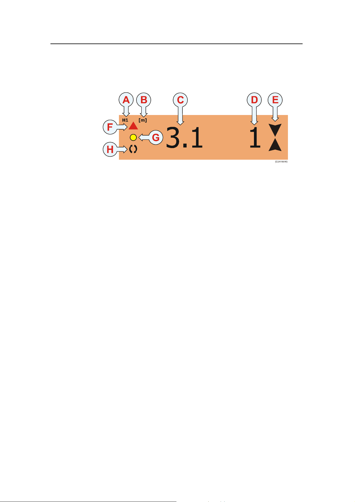
Height pre sentation
The Height sensor presentation is shown below.
(A) The character and the number identifies the type of sensor,
and which identification number the sensor has on the PI44
system. In this example, H1 means that it is a height sensor, and
that it is sensor no.1.
(B) Unit of measure. [m] means meter, [ft] means feet, [fm]
means fathoms and [pb] means braccia.
(C) Readout of the actual height between the sensor and the sea
bottom.
(D) Speed of increasing or decreasing depth. The two arrows
(E) are used to indicate if the distance is increasing or
decreasing. If the depth is constant and the speed is 0, the
arrows are removed.
(E) Depth increase/decrease indicators. If the two arrows point
towards each other (as shown in the example), the depth is
decreasing.
(F) Graphic alarm. The direction of the triangle indicates if the
depth should be increased or decreased with regard to the
selected alarm limits. I f requested, this graphic alarm may be
accompanied with an audible alarms.
(G) Yellow pulse lamp blinks each time a signal is received
from the corresponding sensor.
(H) Interference warning, activated when the PI44 detects
interference from other nearby vessel(s) operating on the same
channel or with similar hydroacoustic equipment. Contact your
Simrad dealer to select a different frequency should this
problem persist.
38
850-165085 / Rev.B
Page 51

Display modes
Spread presentation
The Spread sensor presentation is shown below.
(A) The character and the number identifies the type of sensor,
and which identification number the sensor has on the PI44
system. In this example, S3 means that it is a spread sensor, and
that it is sensor no.3.
(B) Unit of measure. [m] means meter, [ft] means feet, [fm]
means fathoms and [pb] means braccia.
(C) Readout of the actual distance between the two trawl doors.
(D) Increasing or decreasing distance speed of the trawl door
distance shown in units per minute. The two arrows (E) are used
to indicate if the distance is increasing or decreasing. If the
distance is constant and the speed is 0, the arrows are removed.
(E) Distance increasing/decreasing indicators. If the two arrows
point away from each other (as shown in the example), the
distance is increasing.
(F) Graphic alarm. The direction of the triangle indicates if the
trawl door distance should be increased or decreased with regard
to the selected alarm limits. If requested, this graphic alarm may
be accompanied with an audible alarms.
(G) Yellow pulse lamp blinks each time a signal is received
from the corresponding sensor.
(H) Interference warning, activated when the PI44 detects
interference from other nearby vessel(s) operating on the same
channel or with similar hydroacoustic equipment. Contact your
Simrad dealer to select a different frequency should this
problem persist.
850-165085 / Rev.B
39
Page 52

Simrad PI44
Temperature presentation
The temperature sensor presentation is shown below.
(A) The character and the number identifies the type of sensor,
and which identification number the sensor has on the PI44
system. In this example, T2 means that it is a temperature
sensor, and that it is sensor no.2.
(B) Temperature readout.
(C) Unit of measure in Celcius or Fahrenheit. When
presentation space is limited, the unit of measure is shown in the
top left corner.
(D) Temperature trend, indicates if the temperature is falling or
rising. An arrow pointing up this indicates that the temperature
is increasing, while an arrow pointing down indicates decreasing
temperature.
(E) Graphic alarm. The direction of the triangle indicates if the
temperature is higher or lower than a predefined limit.
(F) Yellow pulse lamp blinks each time a signal is received from
the corresponding sensor.
(G) Interference warning, activated when the PI44 detects
interference from other nearby vessel(s) operating on the same
channel or with similar hydroacoustic equipment. Contact your
Simrad dealer to select a different frequency should this
problem persist.
40
850-165085 / Rev.B
Page 53

Display modes
Graphic display
The graphic display provided by the PI44 offers an accurate
echo sounder combined with numeric readouts from the net
sensors.
The graphic sounder display can be set up as a full screen
feature, but you can also set it up to be displayed in smaller
windows. Depending on the window size, the echo sounder and
sensor data may be shown with different layouts, and even with
some of the information removed due to the limited space
available.
Note that some of the information provided by the graphic
presentation assumes that you have the relevant sensors
connected to your PI44 system.
This illustrations shows a graphic display with numerical information along the top,
and an echo sounder presentation below. Additional information from the sensors can
be superimposed on the echo sounder presentation.
850-165085 / Rev.B
41
Page 54

Simrad PI44
The graphic display presentation will provide a lot of
information. The example shown above provides the following
data.
(A) Numeric information
In this example, the information from a Bottom Contact sensor
is shown. The trawl has currently lifted off the seabed.
(B) Numeric information
In this example, the information from a Spread sensor is shown.
The trawl opening is currently 65.5 meters wide, but the
opening is decreasing by 13 meters per minute.
(C) Numeric information
In this example, the information from a Catch sensor is shown.
The sensor has been triggered, so we assume that the net is
about to be filled.
(D) Numeric information
In this example, the information from a Depth sensor is shown.
The current depth is 10.5 meters, and it is decreasing with 5
meters per minute.
(E) Numeric information
In this example, the information from a Temperature sensor is
shown. The current temperature is 1.5 degrees, and the
temperature is decreasing.
(F) Numeric information
In this example, the information from a Height sensor is shown.
The current distance from the head rope to the sea bottom is
32.8 meters, and the depth is decreasing by 3 meters per minute.
(G) Additional information
To switch this information bar on or off, use the Graphic setup.
From left, the following information is provided:
• echo sounder frequency
• transmit power
• pulse width
• ambient temperature
• vessel speed
• depth (depth under keel (DK) is shown in the example)
42
If you use the selector pad to adjust the depth of the VRM
(Variable range marker) or the echo sounder receiver gain, it
will show you the current depth and gain settings while you do
this.
850-165085 / Rev.B
Page 55

Display modes
(H) Time scale
Elapsed time since sounding (ping). Note that the time scale will
change depending on the chosen scroll speed. To switch the time
scale on or off, use the Graphic setup.
(I) Depth scale
In the Echo presentation setup, this scale can be set up change
automatically depending on the current depth. To open this
setup page, press the ENT button to open the Echo quick
menu.
(J) A-scope presentation
To switch this presentation on or off, press the ENT button to
open the Echo quick menu.
(K) Colour scale
This scale shows how the echoes are presentes, The strongest
echoes are displayed using the colour on the top of the scale,
while the weakest echoes are displayed using the coloutrs at the
bottom of the scale. If you choose to see the temperature scale,
it will replace the colour scale.
(L) Bottom echo
In the example, t he bottom contour is shown.
(M) Fish echo
In the example, small schools of fish can be seen.
Informationnotshowninthisexample
Temperature scale: When requested, a temperature scale can be
displayed. It will then replace the colour scale. To switch the
temperature scale on or off, press the ADJ button to open
Graphic setup, then select the Temperature menu.
Depth bars: Depth information from relevant sensors can be
shown as vertical bars on the right side of the display. The depth
bars will replace the A-scope presentation. Each vertical bar will
use the same colour as the current background colour of the
relevant numeric display. To switch the depth bars on or off,
press the ENT button to open the Echo quick menu.
Superimposed sensor information: You can make information
from the sensors appear on the graphic display. To do this, press
the ADJ button to access the Graphic setup, and choose the
Marker line and Trawl info menus. The information from the
sensors will appear as lines on the display, and each line will use
the same colour as the current background colour of the relevant
numeric display.
850-165085 / Rev.B
43
Page 56

Simrad PI44
To change presentation parameters
The graphic display presentation is controlled by the parameters
defined in the graphic and echo presentation setups.
• To change the graphic parameters, press the ADJ button.
• To access the Echo quick menu to switch A-Scope and
depth bars on and off, press the ENT button.
• To change the echo presentation parameters, press the ENT
button to access the Echo quick menu, and then select Echo
presentation setup.
• To change presentation units, press the MENU button to
open the main menu, and then select Speed alarm, unit s and
settings on the Setup menu.
Related topics
→ Graphic setup, page 184
→ Echo presentation setup, page 177
44
850-165085 / Rev.B
Page 57

Display modes
Surface t emperature
The Surface temperature display shows the current
temperature. By means of the graph it will also show you the
temperature history for the past minute. The presentation is
activated from the Fishery menu. To have this information
available, you must have the relevant temperature feeler
connected to your PI44 system. A suitable feeler is integrated
with several Simrad echo sounder transducers, or it may be
connected as a separate peripheral.
850-165085 / Rev.B
To change presentation parameters
The graphic display presentation is controlled by the parameters
defined in the setup. To change the surface temperature
parameters, press the ENT or ADJ buttons to access the
Surface temperature setup.
Related topics
→ Surface temperature setup, page 219
45
Page 58

Simrad PI44
Status display
The Status display shows sensor data, signal thresholds and
background noise levels providing an overview of present
hydro-acoustical conditions and the margin for reliable signal
detection. Other information displayed includes cable status,
program version, and echo sounder / position information.
Note that some of the information provided by the Status
display assumes that you have the relevant sensors connected to
and operational on your PI44 system.
The Status display can only be set up as a full screen feature.
46
Information fields
The infor mation provided by the Status display can be divided
into five fields:
(A) = Numeric information from the sensors
(B) = Upper status field
(C) = Frequency spectrum for noise monitoring
850-165085 / Rev.B
Page 59

Display modes
(D) = Gain indicators for the current sensors
(E) = Lower status field
(A) Numeric information
The numeric displays at the top of the Status display provide
the current information from the active sensors. Due to the lack
of space, the information from the sensors have been
abbreviated slightly. For a more detailed presentation, you must
select the the Numeric display presentation.
(B) Upper status field
The upper status field provides an overview of key parameters.
Receiver setup: All the parameters on the left side are those
defined by the Receiver setup dialogue. To change these, press
the MENU button to access the Setup menu (4), and select
Receiver setup (6).
SW: This sentence provides the current software version in your
PI44 system. Main is the operational software providing the
user interface, µC is the PI44 microcontroller, while DSP is the
software controlling the digital signal processor, that is the
reception and interpretation of sensor information.
Max sh. speed: This is the maximum shooting speed as defined
in the Receiver setup dialogue.
Demo: This entry shows you if the sensor demonstration mode
has been activated. To switch the Demo mode on or off, access
the Sensor setup.
Last received ch: This entry shows you which of the sensors
that last provided information to the PI44.
Error: This is simply an error code. This information is
provided for test purposes only. Unless a software error occurrs,
the code will be 0 (zero).
Hydrophone: A yellow indicator is provided when the
hydrophone is connected and fully operational. If the indicator
is red, a short circuit has occurred. If the indicator is black, the
PI44 has lost electrical contact with the hydrophone.
850-165085 / Rev.B
NMEA1/2: Any information accepted by the NMEA interface
will provide a green indicator. If the indicator is black, the PI44
is currently not receiving input traffic, however, information
may still be exported continuosly.
47
Page 60

Simrad PI44
(C) Frequency spectrum
This graph provides you with information about the background
noise and the signal strength of the frequency band or channel
number selected. Each vertical bar represents the background
noise for the given frequency or channel, and the level is
measured continuously.
To select spectrum display, press the ADJ button to open the
Status setup dialogue, and select Spectrum, display to show
Frequency or Channel. In most cases a Channel view will be
most useful to you.
This function is very useful if you have too much noise and this
makes the communication with the sensor unreliable. Switch off
as much electrical, mechanical and acoustic gear and equipment
as possible. Then, switch the systems on again one by one while
keeping an eye on the frequency spectrum. When the “noisy”
system is activated, it is most likely easy to see!
Note that the frequency spectrum presentation depends on the
Interference filter setting.
(D) Gain indicators
There are six gain indicators, one for each of the current
sensors. At the top of each indicator you can see sensor number
and sensor type, at the bottom you can see the sensor’s
communication channel and current update rate.Green colour
indicates that the reception of signals and noise is within normal
specifications. Red colour indicates that the received signal
exceeds the minimum level required for reception, this is
therefore not an error message.
For the technical minded: When no sensors have been deployed,
the indicators will present the mean noise level. This is the noise
in the surrounding water, caused by mechanical, electrical,
acoustic and natural disturbances. This noise level should be as
low as possible. When a sensor in the water transmits its
information back to the PI44, this is indicated as the green
indicator extends above the mean noise level. In order for the
reception circuitry to accept and recognize the signal, it must be
stronger than a predefined minimum level. The level is normally
referred to as the detection level. If the signal is stronger than
the detection level, the indicator bar will change colour to red.
48
850-165085 / Rev.B
Page 61

Display modes
(E) Lower status field
The lower status field provides an overview of key parameters.
Geographical location: At the left side of the field, the curret
geographic location is provided. Note that this information can
only be displayed if a positioning system has been connected to
the PI44.
COG: Current course over ground. Note that the course
information can only be provided if the relevant sensor (GPS)
has been connected to the PI44.
SOG: Current speed over ground. Note that the speed
information can only be provided if the relevant sensor (GPS)
has been connected to the PI44.
W ater speed: Current speed in the water. Note that the speed
information can only be provided if the relevant sensor (GPS or
speed log) has been connected to the PI44.
Echo 38kHz: This entry provides the current status of the low
frequency echo sounder, as well as its current pulse length and
detection threshold.
Echo 200kHz: This entry provides the current status of the high
frequency echo sounder, as well as its current pulse length and
detection threshold.
Water temp: This entry provides the current water temperature.
Note that this information can only be provided if the relevant
sensor have been connected to the PI44.
Time and date: This entry is a readout of the current time and
date.
Related topics
→ Receiver setup, page 208
→ Status setup, page 218
850-165085 / Rev.B
49
Page 62

Simrad PI44
Echo sounder display
The PI44 offers an accurate echo sounder with a colour display.
The echo sounder can operate on 38, 50 or 200 kHz, and with
two frequencies simultanously. In order to enjoy the echo
sounder functionality, you must have one or two echo sounder
transducers installed.
Note that some of the information provided by the echo sounder
presentation assumes that you have the relevant sensors
connected to your PI44 system.
The echo sounder display can be set up as a full screen feature,
but you can also set it up to be displayed in smaller windows.
Depending on the window size, the echo sounder data may be
shown with different layouts, and even with some of the
information removed due to the limited space available.
50
The following information is provided in the echo sounder
presentation.
(A) Current primary technical parameters.
(B) Current course.
850-165085 / Rev.B
Page 63

Display modes
(C) Current ambient air temperature.
(D) Current vessel speed
(E) Current wind speed
(F) Depth under keel
(G) Time scale: Elapsed time since sounding (ping). Note that
the time scale will change depending on the chosen scroll speed.
(H) Depth scale: This scale can be set up change automatically
depending on the current depth.
(I) A-scope presentation.
(J) Colour scale. This scale shows how the echoes are presentes,
The strongest echoes are displayed using the colour on the top
of the scale, while the weakest echoes are displayed using the
coloutrs at the bottom of the scale.
(K) Bottom echo
(L) Fish echo
The presentation is controlled by the parameters defined in the
presentation setup. To change these parameters, press the ENT
button to open the Echo quick menu, and choose Echo
presentation setup. To change presentation units, press the
MENU button to open the main menu, and then select Speed
alarm, units and settings on the Setup menu.
In the Echo sounder setup you can change the readout for
current depth (F), and you can disable the time scale. These
setup parameters are available on the Setup menu.
Bottom expansion
The PI44 provides a Bottom expansion function. When enabled
the vertical area close to the seabed is expanded. The resulting
presentation will not show the depth variations, as the bottom
will appear flat. However, echoes close to the bottom will be
enhanced. Note that the depth range in this presentation will be
“upside down”, as the seabed is defined as level “0”.
850-165085 / Rev.B
To enable the Bottom expansion function, press the B-LCK
button on the keypad. To disable it, press the STND button. The
vertical depth range of the bottom expansion function is
controlled by the Expansion window parameter in the Echo
presentation setup.PresstheADJ button to access this setup
page.
51
Page 64

Simrad PI44
A-Scope
The PI44 provides an A-Scope function. This presentation
provides the echo from the latest ping only. The strength of the
returned signal from various depths in the water column are
indicated by the horizontal deflections from the Y-axis. This
presentation is very useful if you wish to search for single fish,
as those echoes are hard to see on the regular echogram. Also,
the presentation will give an indication on how strong the
various echoes are.
To enable this function, press the ENT button to open the Echo
quick menu, and select Activate A-Scope. To disable it, select
Hide A-Scope on the same menu.
To change presentation parameters
The echo sounder presentation is controlled by the parameters
defined in the setup. To change these parameters, make the
presentation window active, and press the ADJ (Adjust) to
access the Echo presentation setup page. You can also press
the ENT key to access the Echo quick menu, and select the
Echo presentation setup there.
The technical parameters for the echo sounder are located on the
Echo sounder setup page. To access, press the MENU button,
and select Echo sounder setup on the Setup menu.
Related topics
→ Echo presentation setup, page 177
→ Echo sounder setup, page 180
52
850-165085 / Rev.B
Page 65

Display modes
Highway display
The navigation display provided by the PI44 offers all key
information related to waypoint navigation. Note that the
information pr ovided by this presentation assumes that you have
the relevant sensor (GPS) connected to your PI44 system.
The navigation display can be set up as a full screen feature, but
you can also set it up to be displayed in smaller windows.
The following information is
provided by the navigation
display:
(A) “C” is the current course
over ground, while “B” is the
course to the next waypoint.
(B) “X” is the cross-track error,
while “D” is the distance to the
next waypoint.
(C) ”S” is the current speed
over ground, while “V” is the
speed towards the next
waypoint.
(D) These are the crosstrack
error alarm lines.
(E) The ideal course line
between the two waypoints.
To change presentation parameters
The presentation is controlled by the parameters defined in the
PI44 setup. To change these parameters, press the ADJ or ENT
button to open the Navigation setup page.
To access the Pilot/Position parameters, press the MENU
button to access the main menu. Then. select Pilot/Position
Setup on the Setup menu.
Related topics
→ Navigation setup, page 200
850-165085 / Rev.B
→ Pilot/Position setup, page 200
53
Page 66

Simrad PI44
Position display
The Position display provided by the PI44 offers all key
information related to safe navigation on one display
presentation. Note that the information provided by the Position
display assumes that you have the relevant sensors (GSP and
temperature feeler) connected to your PI44 system.
The Position display can be set up as a full screen feature, but
you can also set it up to be displayed in smaller windows.
The following information is
provided by the position
display:
W ater temperature: The
temperature will only be
available if the applicable
temperature feeler is connected
to the PI44.
Two individual distance logs:
Both distance logs can be reset
using the setup parameters.
Current geographical
position: If the position fails to
be updated, the characters will
flash.
Current speed, course and depth: This information will only
be available if the applicable sensors have been connected to the
PI44.
Local time and date
External POS: This is the current status of the satellite
reception. The character “A” means that the reception is good,
“B” means that the reception is acceptable, and “C” means that
it is poor. If there is no reception, the message Not valid will be
shown.
To change presentation parameters
The presentation is controlled by the parameters defined in the
PI44 setup. To change these parameters, press the ADJ or ENT
buttons to open the Position display setup page. To access the
Pilot/Position parameters, press the MENU button to access the
main menu. Then. select Pilot/Position Setup on the Setup
menu.
54
Related topics
→ Position display setup, page 206
→ Pilot/Position setup, page 200
850-165085 / Rev.B
Page 67

OPERATIONAL PROCEDURES
Overview
This chapter will provide you with basic procedures in order to
help you set up the most common functions and parameters in
the PI44.
Operational procedures
Sensor procedures
→ How to show or hide the graphic
alarm, page 56
→ How to show or hide the sensor timers,
page 56
→ How to reset the sensor timers,
page 56
→ How to change background colour,
page 56
→ How to set up the sensors, page 58
→ How to mount the sensors on the net,
page 61
→ How to use the sensors, page 62
→ How to replace the sacrificial water
switch, page 63
→ How to test the sensors, page 64
→ How to calibrate the Depth sensor,
page 65
→ How to define sensor offsets, page 66
→ How to set up a Spread sensor for a
twin trawl, page 67
→ How to set up a Spread sensor for a
dual twin trawl, page 72
Echo sounder procedures
→ How to access echo sounder
parameters, page 88
→ How to use visual aids and filters,
page 89
→ How to define range, page 91
→ How to zoom in on bottom echoes,
page 93
→ How to zoom in on pelagic echoes,
page 94
→ How to activate the A-Scope
presentation, page 95
Common procedures
→ How to define alarm limits, page 96
→ How to select menu language, page 99
→ How to control automatic page
rotation, page 100
→ How to restore default settings, page
101
→ How to personalize your system,
page 102
Graphic display procedures
→ How to access graphic display
parameters, page 79
→ How to view echo sounder data,
page 80
→ How to set up marker lines, page 81
→ How to use the special features for
trawl markers, page 86
850-165085 / Rev.B
55
Page 68

Simrad PI44
How to define sensor presentation
The information from the various sensors are provided by the
Numerical display, where each sensor is presented in its own
rectangular data winsow.
How to show or hide the graphic alarm
1 Ensure that you have a Numeric display presentation in
your active window.
2 Press the ADJ button to open the Numeric setup
dialogue.
3 Switch Show graphic alarm on or off.
4 Press the ENT button to save the parameters and exit.
How to show or hide the sensor timers
Sensor timers are only used on Catch and Bottom Contact
sensors.
1 Ensure that you have a Numeric display presentation in
your active window.
2 Press the ADJ button to open the Numeric setup
dialogue.
3 Switch Sensor timer on or off.
4 Press the ENT button to save the parameters and exit.
How to reset the sensor timers
Sensor timers are only used on Catch and Bottom Contact
sensors.
1 Ensure that you have a Numeric display presentation in
your active window.
2 Press the ADJ button to open the Numeric setup
dialogue.
3 Set Reset sensor timers to YES.
4 Press the ENT button to save the parameter and exit.
5 Press the ENT button one more time to accept the process.
The next time you access the Numeric setup dialogue, the value
for Reset sensor timers is NO.
56
How to change the background colour
You can change the background colours on the rectangular data
windows in order to easily distingush them from each other.
1 Press the ENT button to open the manin menu.
850-165085 / Rev.B
Page 69

Operational procedures
2 On the Setup menu, select Palette setup.
3 Observe the first palette page appear. It contains fixed
colours, which can not be altered. Press the + button
repeatedly until you reach a custom page.
4 By means of the circular Selector pad and the + and -
buttons, select the requested colour(s).
5 Press the ENT button to accept the choice.
Related topics
→ Numeric setup, page 202
→ Numeric display, page 33
850-165085 / Rev.B
57
Page 70

Simrad PI44
How to set up the sensors
The very first time you switch on the PI44, you will need to set
up the sensor configuration. This will also be required if you
perform a “master reset” on the PI44, and then reload the
manufacturer’s default settings.
Observe the following procedure to establish the most common
values. For more detailed information about the settings, refer to
the References chapter.
Note: In order to establish the sensor configuration, you need to know
what kind of sensors you have, which channels they
communicate on, and how often they communicate. This
information is required before you start the configuration on the
PI44.
Note: Do not attempt to set up the sensors unless this is absolutely
necessary.
We strongly suggest that you use the forms in the front of this
manual to write down the sensor you have with information
about their update rates and communication channels.
1 Press the MENU button to open the main menu.
2 Open the Setup menu (4), and select Sensor setup (5).
3 Press the ENT key to bypass the warning page.
4 For each of the sensors you shall use, select the following
parameters:
a Set Sensor type to SINGLE to activate the sensor.
b Set Update rate FAST, SLOW or NORMAL
c Set Measure to chosen sensor type.
d Set Channel to correct communication channel for the
chosen sensor.
5 For operational use, make sure that Demo mode is set to
OFF.
6 When you have defined the sensors, press the ENT
buttom to save the changes and exit.
If you configure less then six sensors, you will be able to set the
Sensor parameter to Dual. You can not use this setting. Dual
sensors are not yet available, and this functionality is not yet
supported by the digital signal processing in the PI44. The
ability to choose Dual is implemented for future expansion only,
and any attempt to choose this setting will not work.
58
850-165085 / Rev.B
Page 71

Operational procedures
Predefined settings
Each sensor is delivered with a predefined setup. This setup
includes:
• transmission channel for the acoustic communication link
between the sensor and the vessel’s hydrophone
• update rate; how often the sensor sends its readings back to
the PI44 system.
To change the sensor setup, you can call your local Simrad
dealer, or you can do it yourself if you have the proper
equipment, training and the PI Configurator software.
Changing a transmission channel
It may be required to change one or more transmission channels,
and there may be many reasons for this.
• You have more than one of each sensor. For example, if you
have three temperature sensors, they MUST communicate on
three different channels.
• Other vessels near your use the same PI44 system (or a
similar), and they have one or more of their sensors set up to
the same communication channels as you have. This will
create interference, as you will “read” each others sensors.
• If your sensors are set up to use communication channels too
close to each other (for example, you have chosen channels
4, 5 and 6), this will limit the vessel’s speed. The reason for
this is the doppler effect. If the speed is too high, the doppler
will cause the transmission frequencies to change so much
that they overlap, and this will create interference. The PI44
will provide a warning if this is about to happen! You must
then either change to other communication channels further
apart, or reduce the maximum shooting speed.
• If you operate at the maximum range of the sensors, you may
be able to increase this range slightly if you use lower
communication channels. This is because the lower
communication channels user lower transmission
frequencies.
Changing the update rate
850-165085 / Rev.B
It may be required to change the update rate on a sensor, that is
how often it sends information back to the PI44 system. A high
update rate will give frequent information updates, but the
sensor will use more battery power. If you need your batteries to
last as long as possible, you must consider lowering the update
rate.
59
Page 72

Simrad PI44
• A low update rate will provide you with fewer information
updates, but the battery will last very long.
• A high update rate will give you frequent information
updates, but the battery will run out faster.
All sensors are provided from Simrad with a default update rate
setting. In some cases you may find that this update rate does
not suit your operational needs. This is a decision you have to
make depending on the local fishing conditions.
How to change the sensor setup
To change the sensor setup, you can call your local Simrad
dealer, or you can do it yourself if you have the proper
equipment, training and the PI Configurator software.
Related topics
→ Sensor setup, page 215
→ Max shooting speed, page 208
→ PI Configurator, page 226
60
850-165085 / Rev.B
Page 73

Operational procedures
How to mount the sensors on the net
Once the sensor has been coded correctly, you must mount it on
the net. The mounting instructions for each sensor is provided in
the Sensors chapter, and the same information can also be found
on the Quick Reference Guide for each sensor.
Related topics
→ Sensors overview, page 103
850-165085 / Rev.B
61
Page 74

Simrad PI44
How to use the sensors
Once the sensors have been coded and installed on the net, they
will automatically be switched on once they are submerged into
water. The PI44 will then automatically retreive information
from them, and provided that you have chosen the correct
display presentation, the information will be provided to you.
Applications
The various applications available to you with the different
sensors are explained in the Getting started and Applications
chapters.
Display presentation
How to set up the display to see the information provided by the
sensors are described in the Getting started chapters. The
various modes are explained in detail in the Display modes
chapter.
Practical information
The practical information about the various sensors is provided
in the Sensors chapter, and the same information can also be
found on the Quick Reference Guide for each sensor.
Related topics
→ Getting started: Presentation pages, page 13
→ Getting started: Sensors, page 20
→ Applications, page 25
→ Sensors overview, page 103
62
850-165085 / Rev.B
Page 75

Operational procedures
How to replace the sacrificial water switch
All PI and PS sensors are equipped with a water switch, and two
different types are used. If your sensors are equipped with a
brass screw, observe the following procedure for replacement.
1 Turn the sensor upside down, and locate the brass screw.
2 Inspect the screw for wear and tear. If required, replace
the screw.
A standard commercial brass screw is used. Local supply will
normally be available, but the following specifications must be
met:
Brass, Size M5x10, DIN85A, rounded head
Before a new screw is inserted, Aqua Shield (or a similar
underwater lubricant) must be applied. Due to the size of the
tube, we recommend that the grease is applied from a syringe.
1 Apply Aqua Shield to the screw threads.
2 Insert the screw, mount firmly, but not too hard.
3 Use maximum torque 1.5 NM
A pack with ten screws and a tube of Aqua Shield can be
ordered from Simrad as a spare parts kit.
Aqua Shield is manufactured by D.A.Stuart, Warrenville,
Illinois, USA (www.d-a-stuart.com).
850-165085 / Rev.B
63
Page 76

Simrad PI44
How to test the sensors
By using the PI Configurator, you can test the operational status
of each sensor. Test procedures for all the sensors have been
provided in a separate chapter in this manual.
Note that PI and PS sensors are tested using the same
procedures.
Related topics
→ PI Configurator, page 226
→ Test procedures, page 265
64
850-165085 / Rev.B
Page 77

Operational procedures
How t o calibrate the Depth sensor
Only the Depth sensor can be calibrated. The purpose is to
ensure that the depth reported by the sensor is as accurate as
possible.
This procedure is carried out onboard the vessel.
1 Mount a rope to the top fastening lugs on the sensor.
2 Tighten the rope, and measure one meter from the bottom
of the sensor to a spot on the rope. Place a visual marker
on the rope at that location.
3 Lower the sensor over the side of the vessel and into the
water. Lower it until the visual marker on the rope is even
with the surface.
4 On the PI44, observe the numerical presentation of the
sensor, and allow the reading to stabilize itself.
5 On the PI44, press the MENU button to open the Main
menu.
6 Press 4 to open the Setup menu, and 4 againtoopenthe
Sensor alarm/calibration dialogue.
7 Press the GAIN+ button three -3- times to access the
Depth calibration dialogue.
8 Set Depth sensor calibration to YES.
9 Press the ENT button to accept the choice, and one more
time to acknowledge.
10 Observe the information page. Press the ENT button once
again to proceed.
11 Leave the sensor hanging from the rope for minimum two
minutes. Meanwhile, observe that the numerical
presentation shows grey characters only.
12 On the PI44, observe that the numerical presentation of
the Depth sensor is stable, and shows 1 meter.
13 Retrieve the sensor from the water.
Note: In order to calibrate the sensor, it must be submerged in salt
water.
You may wish to use a different depth reference than the sea
surface. If this is the case, change the marking on the rope to fit
you preference, for example the depth of the keel or the depth of
an echo sounder transducer.
850-165085 / Rev.B
Related topics
→ How to define sensor offsets, page 66
→ Depth calibration, setup, page 176
65
Page 78

Simrad PI44
How to define sensor offsets
Only the Depth and Spread sensors can have their offset values
adjusted. The purpose is to allow you to compensate for known
deviations.
You may wish to insert a Depth sensor offset to line up the
depth readings from the sensor with those from your echo
sounder. If the echo sounder transducer is located X meters
below the surface, the Depth sensor should have the same offset
value.
Note: If you have performed a Depth sensor calibration, you will see
than an offset value may already be present. This value has been
provided by the calibration routine.
1 On the PI44, press the MENU button to open the main
menu.
2 Press 4 to open the Setup menu, and 4 againtoopenthe
Sensor alarm/calibration dialogue.
3 Press the GAIN+ button four -4- times to access the
Offset adjust dialogue.
4 Enter the required values.
5 Press the ENT button to save the parameters and exit.
Related topics
→ Offset adjust, setup, page 203
66
850-165085 / Rev.B
Page 79

Operational procedures
How to set up a Twin Spread sensor for
twin trawl applications
By means of the T win Spread sensor, you can set up your PI44
to monitor the openings on a twin trawl. Apart from the Twin
Spread sensor, you will also need two Remote sensors.
Sensor configuration
The Twin Spread and Remote sensors are supplied in sets, and
they MUST operate in these sets. The sets are:
• Twin Spread 1 uses two Remote sensors; Remote 1 and
Remote 3.
• Twin Spread 2 uses two Remote sensors; Remote 2 and
Remote 4.
When supplied from the manufacturer, all Twin Spread sensors
are set up as Tw in Spread 1. If you wish to use a Twin Spread 2,
your dealer (or yourself) must reconfigure the sensor using the
PI Configurator application.
Communication channels and update rate
Each Twin Spread sensor will communicate on two channels,
one for each of the two distances the sensor measures. By
default, these communication channels are set to 02 and 07.
• Channel 02 is used to measure the distance to Remote 1.
• Channel 07 is used to measure the distance to Remote 3.
By default, both communication channels are set up with Fast
update rate. In order to increase the lifetime between each
sensor charging, you may consider changing to Normal update
rate.
If you wish to reconfigure the settings, your dealer (or yourself)
must use the PI Configurator application.
Placing the sensors on the trawl
The Twin Spread sensor must be mounted on the port trawl
door, and the three communication transducers on the sensor
must not be obstructed. Ensure that you have a clear line of
sight between the tip of the Twin Spread sensor and the vessel,
and between the Twin Spread sensor and the two Remote
sensors.
850-165085 / Rev.B
Remote 1 is placed on the centre clump.
Remote 3 is placed on the starboard door.
67
Page 80

Simrad PI44
This configuration will allow the Twin Spread sensor to measure
the distance from the port door to the centre clump directly. It
will also measure the distance between the two trawl doors. In
order to calculate the distance between the centre clump and the
starboard door, you must perform the required settings on the
PI44.
68
(P) = Port trawl
(S) = Starboard trawl
(C) = Port trawl door with the Twin Spread 1 sensor mounted.
(D) = Centre clump with Remote 1 mounted.
(E) = Starboard trawl door with R emote 3 mounted.
(F) = Forward
(1) = Distance between port trawl door and centre clump,
measured direcly by the Twin Spread sensor.
(2) = Distance between the centre clump and the starboard
trawl door, must be calculated by the PI44 system.
850-165085 / Rev.B
Page 81

Operational procedures
Sensor setup
Observe the procedure below to set up a Twin Spread
configuration with its default settings.
In this procedure, sensors 1 and 2 are used, and no other sensors
are shown. Due to the fact that the T win Spread sensor occupy
two communication channels, the setup program requires that it
is configured as if it was two separate sensors, but not
necessarily sensors 1 and 2. The remaining four channels can be
used for other sensors.
We strongly suggest that you use the forms in the front of this
manual to write down the sensor you have with information
about their update rates and communication channels.
1 Press the MENU button to open the main menu.
2 Open the Setup menu (4), and select Sensor setup (5).
3 Press the ENT key to bypass the warning page.
4 To configure the Twin Spread sensor, enter the following
parameters:
a Set Sensor 1 type to SINGLE to activate the sensor.
b Set Update 1 rate to FAST.
c Set Measure 1 to SPREAD.
d Set Channel to 02.
e Set Sensor 2 type to SINGLE to activate the sensor.
f Set Update 2 rate to FAST.
g Set Measure 2 to SPREAD.
h Set Channel to 07.
5 For operational use, make sure that Demo mode is set to
OFF.
6 When you have defined the sensors, press the ENT
buttom to save the changes and exit.
850-165085 / Rev.B
69
Page 82

Simrad PI44
According to the sensor locations previously described, Spread
1 will now measure the distance from the port trawl door to the
centre clump, while Spread 2 will measure the distance from the
port trawl door to the starboard trawl door.
Readout adjustments
It is necessary to set certain parameters in order to have the PI44
to calculate the distance from the centre clump to the starboard
trawl door.
GAIN- GAIN+
Headrope sensor:
Footrope sensor:
Trawl opening mode:
Manual trawl marker:
Clump sensor:
Door sensor:
Trawl data in additional info:
Type of trawl data:
MENU Exit
Trawl info
SPREAD 1
SPREAD 2
ON
SPREAD
(CD11105C)
1 Press the MENU button to open the main menu.
2 Press the WIN button to select a full screen presentation.
3 Open the Fishery menu, and select a Graphic display.
4 Press the ADJ button to open the Graphic setup.
5 Press the PAGE+ button three -3- times to access the
Trawl info dialoge.
6 Locate the Clump sensor setting, select SPREAD 1.
- As previously defined and described, sensor Spread 1
measures the distance between the port trawl door and
the centre clump.
7 Locate the Door sensor setting, select SPREAD 2.
- As previously defined and described, sensor Spread 2
measures the distance between the port and the
starboard trawl doors. This setting allows the PI44 to
calculate the distance between the clump and the
starboard trawl door.
8 Locate Trawl data in additional info, select ON.
70
9 Locate Type of trawl data, select SPREAD.
10 Press the ENT button to save the settings and exit.
Readouts
Following the configuration and readout adjustments explained,
the following readouts are now available in the Graphic
display.
850-165085 / Rev.B
Page 83

Operational procedures
• Numeric display: Rectangle S1 shows the distance between
the port trawl door and the centre clump. Rectangle S2 shows
the distance between the port trawl door and the starboard
trawl door.
• Additional information: The information bar directly below
the numeric rectangles displays the abbreviation TS and a
value. This value represents the distance between the centre
clump and the starboard trawl door.
Related topics
→ Twin Spread, page 148
→ Sensor setup, page 215
→ Trawl info, page 223
850-165085 / Rev.B
71
Page 84

Simrad PI44
How to set up two Twin Spread sensors
for dual twin trawl application
By means of two Twin Spread sensors, you can set up your PI44
to monitor the four openings on a dual twin trawl. Apart from
the two Twin Spread sensors, you will also need four Remote
sensors.
72
(A) = Twin trawl Alpha (Port)
(B) = Twin trawl Bravo (Starboard)
850-165085 / Rev.B
Page 85

Operational procedures
Sensor configuration
The Twin Spread and Remote sensors are supplied in sets, and
they MUST operate in these sets. The sets are:
• Twin Spread 1 uses two Remote sensors; Remote 1 and
Remote 3.
• Twin Spread 2 uses two Remote sensors; Remote 2 and
Remote 4.
When supplied from the manufacturer, all Twin Spread sensors
are set up as Twin Spread 1. You will now need to use Twin
Spread 2 as well, and your dealer (or yourself) must reconfigure
aTwinStread1sensorusingthePI Configurator application.
Communication channels and update rate
Each Twin Spread sensor will communicate on two channels,
one for each of the two distances the sensor measures. By
default, these communication channels are set to 02 and 07.
• Channel 02 on Twin Spread 1 is used to measure the
distance to Remote 1.
• Channel 07 on Twin Spread 1 is used to measure the
distance to Remote 3.
By default, both communication channels are set up with Fast
update rate. In order to increase the lifetime between each
sensor charging, you may consider changing to Normal update
rate.
When you reconfigure a Twin Spread 1 sensor to act as a Twin
Spread 2, you must also choose two additional communication
channels. You can choose any channels available on your
system.
In this description we will use channels 09 and 11 as follows:
• Channel 09 on Twin Spread 2 is used to measure the
distance to Remote 2.
• Channel 11 on Twin Spread 2 is used to measure the
distance to Remote 4.
If you wish to reconfigure the settings, your dealer (or yourself)
must use the PI Configurator application. Make sure that the
channels you choose are not used by any of your other sensors!
850-165085 / Rev.B
73
Page 86

Simrad PI44
Only twin trawl Alpha (port) is shown.
(P) = Port trawl
(S) = Starboard trawl
(C) = Port trawl door with the Twin Spread 1 sensor mounted.
(D) = Centre clump with Remote 1 mounted.
(E) = Starboard trawl door with R emote 3 mounted.
(F) = Forward
(1) = Distance between port trawl door and centre clump,
measured direcly by the Twin Spread sensor.
(2) = Distance between the centre clump and the starboard
trawl door, must be calculated by the PI44 system.
Placing the sensors on the trawl
The two twin trawls are referred to as Alpha (port) and Bravo
(starboard).
On the twin trawl Alpha, the Twin Spread 1 sensor must be
mounted on the port trawl door, and the three communication
transducers on the sensor must not be obstructed.
74
Remote 1 is placed on the centre clump of Alpha.
Remote 3 is placed on the starboard door of Alpha.
850-165085 / Rev.B
Page 87

Operational procedures
On twin trawl Bravo, the Twin Spread 2 sensor must be
mounted on the port trawl door, and the three communication
transducers on the sensor must not be obstructed.
Remote 2 is placed on the centre clump of Bravo.
Remote 4 is placed on the starboard door of Bravo.
This configuration will allow the Twin Spread sensors on each
dual trawl Alpha and Bravo to measure the distance from the
port door to the centre clump directly. It will also measure the
distance between the two trawl doors.
In order to calculate the distance between the centre clump and
the starboard door, you must perform the necessary settings on
the PI44. This is however only possible with one of the twin
trawls, as the current software version does not support this
function.
Sensor setup
Observe the procedure below to set up a Twin Spread
configuration with the settings defined above.
In this procedure, sensors 1, 2, 3 and 4 are used, and no other
sensors are shown. Due to the fact that each Twin Spread sensor
occupy two communication channels, the setup program
requires that each sensor is configured as if it was two separate
sensors, but not necessarily sensors 1 through 4. The remaining
two channels can be used for other sensors.
We strongly suggest that you use the forms in the front of this
manual to write down the sensor you have with information
about their update rates and communication channels.
1 Press the MENU button to open the main menu.
2 Open the Setup menu (4), and select Sensor setup (5).
3 Press the ENT key to bypass the warning page.
4 To configure the Twin Spread sensor, enter the following
parameters:
a Set Sensor 1 type to SINGLE to activate the sensor.
b Set Update 1 rate to FAST.
850-165085 / Rev.B
c Set Measure 1 to SPREAD.
d Set Channel to 02.
e Set Sensor 2 type to SINGLE to activate the sensor.
f Set Update 2 rate to FAST.
g Set Measure 2 to SPREAD.
75
Page 88

Simrad PI44
h Set Channel to 07.
i Set Sensor 3 type to SINGLE to activate the sensor.
j Set Update 3 rate to FAST.
k Set Measure 3 to SPREAD.
l Set Channel to 09.
m Set Sensor 4 type to SINGLE to activate the sensor.
n Set Update 4 rate to FAST.
o Set Measure 4 to SPREAD.
p Set Channel to 11.
5 For operational use, make sure that Demo mode is set to
OFF.
6 When you have defined the sensors, press the ENT
buttom to save the changes and exit.
According to the sensor locations previously described, the
following measurements are made:
• Twin trawl Alpha (port): Spread 1 will measure the
distance from the port trawl door to the centre clump, while
Spread 2 will measure the distance from the port trawl door
to the starboard trawl door of the port twin trawl.
• Twin trawl Bravo (starboard): Spread 3 will measure the
distance from the port trawl door to the centre clump, while
Spread 4 will measure the distance from the port trawl door
to the starboard trawl door of the starboard twin trawl.
76
850-165085 / Rev.B
Page 89

Operational procedures
Readout adjustments
It is necessary to set certain parameters in order to have the PI44
to calculate the distance from the centre clump to the starboard
trawl door.
Note: This is however only possible for one twin trawl, not for both.
1 Press the MENU button to open the main menu.
2 Press the WIN button to select a full screen presentation.
3 Open the Fishery menu, and select a Graphic display.
4 Press the ADJ button to open the Graphic setup.
5 Press the PAGE+ button three -3- times to access the
Trawl info dialoge.
6 Locate the Clump sensor setting, select Spread 1 (or
Spread 3)
- As previously defined and described, sensor Spread 1
measures the distance between the port trawl door and
the centre clump.
7 Locate the Door sensor setting, select Spread 2 (or
Spread 4)
- As previously defined and described, sensor Spread 2
measures the distance between the port and the
starboard trawl door. This setting allows the PI44 to
calculate the distance between the clump and the
starboard trawl door.
8 Locate Trawl data in additional info, select Yes.
9 Locate Type of trawl data,selectSpread.
10 Press the ENT button to save the settings and exit.
Readouts
Following the configuration and readout adjustments explained,
the following readouts are now available in the Graphic
display.
• Numeric display:
- Rectangle S1 shows the distance between the port door
and the centre clump on twin trawl Alpha (port).
- Rectangle S2 shows the distance between the port and
starboard trawl doors on twin trawl Alpha (port).
850-165085 / Rev.B
- Rectangle S3 shows the distance between the port door
and the centre clump on twin trawl Bravo (starboard).
- Rectangle S4 shows the distance between the port and
starboard trawl doors on twin trawl Bravo (starboard).
77
Page 90

Simrad PI44
• Additional information: The information bar directly below
the numeric rectangles displays the abbreviation TS and a
value. This value represents the distance between the centre
clump and the starboard trawl door on the chosen port (or
starboard) trawl.
Related topics
→ Twin Spread, page 148
→ Sensor setup, page 215
→ Trawl info, page 223
78
850-165085 / Rev.B
Page 91

Operational procedures
How to access graphic display parameters
The various parameters defining the Graphic display
presentation are controlled from the following dialogues:
• Graphic setup
• Temperature
• Marker line
• Trawl info
• Trawl calculator
How to use the most common parameters are explained in
separate procedures.
Access
1 Make sure that you have a Graphic display presentation in
your active window.
2 Press the ADJ button to open the Graphic setup
dialogue.
3 Press the GAIN+ button repeatedly to open the various
setup dialogues.
Related topics
→ Graphic setup, page 184
→ Temperature setup, page 220
→ Marker line setup, page 197
→ Trawl calculator, page 221
→ Trawl info setup, page 223
850-165085 / Rev.B
79
Page 92

Simrad PI44
Howtoviewechosounderdata
When you have chosen the Graphic display presentation, you
can choose to superimpose the information from the echo
sounder. This feature allows you to see where your sensors are
located in relation to the bottom and fish echoes. Note that this
feature will only work if you have mounted an echo sounder
transducer to the PI44.
1 Make sure that a Graphic display presentation is active.
2 Press the ADJ button to open the Graphic setup
dialogue.
3 Locate the setting Superimpose echo sounder, and set the
option to ON.
4 Press the ENT button to save the setting and close the
dialogue.
Related topics
→ Graphic setup, page 184
80
850-165085 / Rev.B
Page 93

Operational procedures
How to set up marker lines
When you have chosen the Graphic display presentation, you
can choose to superimpose the information from the echo
sounder, and then add marker lines to see where your sensors
are located in relation to the bottom and fish echoes. Note that
the echo sounder data will only appear if you have mounted an
echo sounder transducer to the PI44.
The following parameters will affect the way the marker lines
are displayed:
• Width - you can select how thick (in pixels) each marker line
shall be.
• Delay - The echo sounder information is provided by the
transducer, and this transducer is located under the vessel.
The sensors are located on the gear, which may be positioned
several hundred meters behind the vessel. To adjust for this
delay, you can enter a value for Marker line delay.Youmust
calculate this value (in minutes) based on the vessel’s speed,
the wire length and the depth of the gear.
Alternatively, you can use the built-in Trawl caluclator to
find the correct delay.
• Colour - The colour of the marker line is automatically set to
the current Numeric display background colour for the same
sensor. To change that colour, you must access the Display
colour setup page from the Setup menu.
• Expanded view: With the setting Sensor marker in
expansion active, the Depth and Height marker lines are
shown in the expanded areas (Bottom lock, Zoom and Shift),
and thus easier to read. This is a useful feature when the
sensor is towed close to the bottom, and it is particulary
important for the Height sensor.
• Marker white zone: When this setting is enabled, white
pixels are added above and under the marker line to make it
easier to distinguish it from the background colours.
• Height marker in main echogram: This setting is special
for Height sensors. If you have a Height sensor on the top of
a bottom trawl and the trawl opening is small, it may be
difficult to tell the Height marker from the bottom echo. If
this is the case, set this function to Off, and view the Height
marker in expanded mode only.
850-165085 / Rev.B
81
Page 94

Simrad PI44
• Height reference: The Height sensor measures the distance
from the headrope to the bottom. If you use the PI44 echo
sounder, set Height reference to Bottom (default), and the
height marker will follow the bottom contour. If you even
define the delay correctly, you will be able to see the trawl in
true motion. If you do not have en active echo sounder, set
Height reference to Surface. The height will then be shown
with 0 m depth as reference, and the marker line will appear
as a nearly straight line some distance below 0 meters. The
distance from the 0 meter line and down to the marker line
will be the current height of the trawl.
82
(A) = Numeric depth display, Sensor “4D” (Depth)
(B) = Marker line from Depth sensor”4D”
(C) = Numeric depth display, Sensor “6D” (Depth). A different
background colour has been chosen to tell the marker lines
apart.
(D) = Marker line from Depth sensor”6D”
850-165085 / Rev.B
Page 95

Operational procedures
Access to the marker line parameters
1 Make sure that a Graphic display presentation is active.
2 Press the ADJ button to open the Graphic setup
dialogue.
3 Press the GAIN+ button until the Marker line setup
dialogue appears.
4 Observe the list of sensors. Only the sensors capable of
providing data for marker lines are listed.
Trawl calculator
In order to calculate the correct delay, we suggest that you use
the built-in Trawl calculator. Observe the following procedure:
1 Press the GAIN+ button to access the Trawl calculator
setup page.
2 Set Trawl calculator mode to Auto.
3 Set Towing speed to Auto.
- In order to retrieve speed information, the relevant
equipment (GPS) must be interfaced to your PI44.
- When you read the speed information from a GPS, the
information is very accurate. Due to the fact that the
trawl calculations are made continuously, even the
slightest change in speed will be reflected on the
display presentation, and you may experience that the
markers fluctuate. If this is a problem, enter the
average vessel speed manually.
4 If you run a pelagic trawl, set Trawl depth to Manual,
and enter the mean depth.
5 If you run a bottom trawl, you can set the Trawl depth to
Bottom, and read the depth from the echo sounder.
- If a transducer is connected to the PI44, the trawl
calculator will update the delay based on the data from
the echo sounder.
6 Enter the Wire length. In most cases, this is the length
from the stern of the vessel to the trawl doors.
850-165085 / Rev.B
7 Enter the Wire length offset. This is the distance from the
trawl doors to the headrope, and normally a fixed value.
The calculator will add the wire length to the wire length
offset, and use the sum of these in the calculations.
83
Page 96

Simrad PI44
Depth and Height marker lines
The purpose of these marker lines is to provide an easy way to
monitor the depth of the gear. The Height sensor measures the
distance from the seabed and up to the sensor, while the Depth
sensor measures the distance from the sea surface and down to
the sensor.
1 Identify which of the sensors that are the Depth and/or
Height sensors.
2 For each sensor, set Auto to On.
- This enables the PI44 to use the delay calculated by the
Trawl calculator.
- You can also set Auto to Off. You must then calculate
the delay yourself, and enter it manually in the Delay
column.
3 Enter your preferred value for marker line Width.
4 Enable each individual marker line by setting Show to
On.
5 If you wish to see the marker line(s) in expanded view
(Bottom Lock, Zoom and Shift), set the Sensor marker
line in expansion to On.
6 If you wish the PI44 to draw a thin white line over and
under the marker line to enhance the view, set Marker
white zone to On.
7 If you wish to view the Height marker in expanded mode
only, set Height marker in main echogram to Off.
8 Select the appropriate setting for Height reference.
9 Press ENT to save the settings and exit to the graphic
display presentation.
The Depth and Height marker lines are presented on the
Graphic display with continuous lines in the same background
colour as in the Numeric display. To read the depth, consult the
depth range on the right side of the display, or the readout in the
Numeric display.
84
850-165085 / Rev.B
Page 97

Operational procedures
Spread marker line
The purpose of this marker line is to provide an easy way to
monitor the distance between the trawl doors.
1 Identify which of the sensors that is the Spread sensor.
2 Set the marker line to ON.
3 Enter the preferred settings for Marker line thickness
and Marker line delay.
4 Press ENT to save the settings and return the the graphic
presentation.
The Spread marker line is presented on the Graphic display
with a continuous line. The colour of the line is the same as the
background colour in the numeric presentation. To read the
distance between the trawl doors, consult the depth range on the
right side of the display, or the readout in the Numeric display.
If the trawl door distance is reduced or increased, this will be
easily detected as the marker line moves up or down. Note that
you do not monitor the depth of the trawl doors even though
you use the depth scale, the scale is used as a range scale.
Surface temperature marker line
The purpose of this marker line is to provide an easy way to
monitor the surface temperature. Note that this is NOT a reading
from a temperature sensor, but from a feeler. Such feelers are
often built into the echo sounder transducers.
1 Ensure that a proper feeler is connected to the PI44.
2 Set the marker line to On.
3 Enter the preferred settings for Marker line thickness
and Marker line delay.
4 Use the ADJ button to open the Temperature setup page.
5 Press ENT to save the settings and exit to the graphic
display presentation.
The Temperature marker line is presented on the Graphic
display as a continuous line.
Related topics
→ Graphic setup, page 184
850-165085 / Rev.B
→ Marker line setup, page 197
→ Temperature setup, page 220
→ Trawl calculator, page 221
85
Page 98

Simrad PI44
Special f eatures for trawl marker lines
When you have chosen a graphic presentation, you can choose
to superimpose the information from the echo sounder, and then
add marker lines to see where your sensors are located in
relation to the bottom and fish echoes. When you use a pelagic
or bottom trawl, the PI44 offers certain special features to
provide additional information.
(A) = Numeric depth display, Sensor “6D” placed on the
headrope
(B) = Marker line from the footrope, added by using the Manual
trawl marker setting
(C) = Marker line from the headrope using the data from Depth
sensor “6D”
The recommended sensor configuration to monitor the trawl
opening is to use one Height or Depth sensor on the headrope,
and one Depth sensor on the footrope. However, if you only use
one of these sensors, place it on the headrope. The PI44 will
then manually draw the trawl opening markers for you provided
that you enter the typical height of the trawl opening.
The following parameters will provide the extra information
related to trawl markers:
• Headrope and footrope sensors: You need to tell the PI44
which Depth and/or Height sensor(s) you have placed on the
footrope and/or headrope of the trawl.
86
850-165085 / Rev.B
Page 99

Operational procedures
• Trawl opening mode: This parameter decides how the trawl
opening shall be recreated on the graphic presentation. If you
have sufficient sensors on the trawl you must select Auto,
and the the PI44 will automatically calculate the trawl
opening and draw it accordingly. If you only have one sensor
on the trawl opening (Depth or Height sensor on the
headrope), the Manual setting will add an artificial line on
the presentation. The distance from the headrope to the
footrope must then be defined manually using the Manual
trawl marker parameter.
Access to the parameters
1 Make sure that a graphic presentation is active.
2 Press the ADJ button to open the Graphic setup
dialogue.
3 Press the GAIN+ button to access the Trawl info setup
page.
Set up the parameters
1 Locate the setting Headrope sensor, and choose the
sensor that you have placed on the headrope.
- If you have no Depth or Height sensors on the
headrope, leave the setting to None.
2 Locate the setting Footrope sensor, and chose the sensor
that you have placed on the footrope.
- If you have no Depth or Height sensors on the
footrope, leave t he setting to None.
3 Observe that the setting for Trawl opening mode is
automatically set to Auto or Manual.
- If you have sensors placed on both the footrope and the
headrope, the PI44 will be able to calculate the trawl
opening automatically, and the mode is set to Auto.
- If you have only one sensor, you will need to enter a
manual trawl marker.
4 If you have only one sensor, enter a value for Manual
trawl marker.
- This value must represent the actual height of your
trawl opening, based on your knowledge about your
gear. The information will be used by the PI44 to draw
a second trawl marker line.
850-165085 / Rev.B
Related topics
→ Graphic setup, page 184
→ Marker line setup, page 197
→ Trawl info setup, page 223
87
Page 100

Simrad PI44
How to access echo sounder parameters
The built-in echo sounder is easily controlled from separate
dialogues.
• The Echo presentation setup dialogue controls the visual
parameters, such as Range, Gain, White line and Expansion
window.
• The Echosounder setup dialogue controls the operational
parameters, such as alarms, sound velocity and transducer
selection.
How to find the most common parameters are explained in
separate procedures. The parameters are described in detail in
the References chapter.
Echo presentation setup
1 Make sure thast you have an echo sounder presentation in
your active window.
2 Press the ADJ button to open the Echo presentation
setup.
Alternatively, you can press the ENT button to open the Echo
quick menu, and then select Echo presentation setup (9).
Echosounder setup
1 Press the MENU button to open the main menu.
2 Select Setup (4)
3 Select Echosounder setup (STND).
Related topics
→ Echo presentation setup, page 177
→ Echosounder setup, page 180
88
850-165085 / Rev.B
 Loading...