

Page 1
Installation manual
Simrad PI44
Catch monitoring system
www.simrad.com
M A X I M I Z I N G Y O U R P E R F O R M A N C E A T S E A
Page 2

Page 3

851-165101 / Rev.A
Simrad PI44
Catch monitoring system
Installation manual
NOTICE
Operation of the PI44 system assumes that the
communication between the Operator Unit and the
sensors is fully functional. Ensure that the
communication channels defined on the Operator Unit
matches those of the sensors.
Page 4

About this document
Rev Date Written by Checked by Approved by
Rev.A
03.06.05 RBr KR KR
Original issue.
© 2005 Simrad AS
ISBN 82-8066-048-8
All rights reserved. No part of this work covered by the copyright hereon may be
reproduced or otherwise copied without prior permission from Simrad AS.
The information contained in this document is subject to change without prior notice.
Simrad AS shall not be liable for errors contained herein,or for incidental or consequential
damages in connection with the furnishing, performance, or use of this document.
The equipment to which this manual applies must only be used for the purpose for which
itwasdesigned.Improperuseormaintenancemay causedamagetotheequipment or injury
topersonnel. The usermustbefamiliar with the contentsof the appropriate manuals before
attempting to operate or work on the equipment. Simrad AS disclaims any responsibility
fordamageorinjurycausedbyimproperinstallation,useormaintenanceoftheequipment.
If you require maintenance on your Simrad equipment, contact your local dealer. You can
also contact Simrad using the following e-mail address: fish-support@simrad.com
Page 5

Sections
1Introduction
This section provides a general introduction to the PI44 installation. Refer
to page 1.
2 Echo sounder transducer installation
This section provides general guidelines for the installation of the optional
echo sounder transducer. Refer to page 18.
3 Purse hydrophone installation
This section provides general guidelines for the installation of the PI44
purse seine hydrophone. Refer to page 42.
4 Trawl hydrophone installation
This section provides general guidelines for the installation of the PI44
trawl hydrophone. Refer to page 79.
Installation manual
5 Portable hydrophone
This section provides general guidelines for the use of the PI44 portable
hydrophone. Refer to page 120.
6OperatorUnit
This section explains how to install the PI44 Operator Unit cabinet. Refer to
page 127.
7Sensors
This section provides an introduction to PI44 sensors and the configuration
of these. Refer to page 133.
8 Cable layout
This section details all cabling. Refer to page 142.
9Interfacesetup
This section explains how to connect external equipment, such as navigation
and positioning sensors. Refer to page 165.
10 Installing sensor adapters
This section explains how to install the PI Spread and PI Remote sensors on
the trawl doors. Refer to page 179.
11 Software updates
If you need to upgrade the software in your PI44 Operator Unit, the necessary
procedures can be found here. Refer to page 194.
851-165101 / Rev.A
I
Page 6

Simrad PI44
1 INTRODUCTION 1.........................................
System diagram 2..........................................
Scope of supply 3..........................................
Supply conditions 5........................................
General installation requirements 6............................
Equipment handling 7......................................
11 TRANSDUCER INSTALLATION 18..........................
Purpose 18................................................
Transducer location 19.......................................
External mounting 23........................................
Transducer blister 28........................................
Box keel 33...............................................
Cable glands 35............................................
Cable in steel conduit 39.....................................
Handling and maintenance 40.................................
Approved anti-fouling paints 41...............................
12 PURSE SEINE HYDROPHONE 42...........................
Purpose 42................................................
Installation precautions 43....................................
Considerations 44...........................................
Pre-installation check-list 48..................................
Optimal location of purse seine hydrophones 50...................
Coverage area, orientation and tilt 51...........................
Mounting arrangement 54....................................
Dual hydrophone installation 57...............................
Hydrophone protection 59....................................
Hydrophone cable 62........................................
Installation drawings 67......................................
13 TRAWL HYDROPHONE 79...................................
Purpose 79................................................
Installation precautions 80....................................
Considerations 81...........................................
Pre-installation check-list 86..................................
Optimal location of trawl hydrophones 88.......................
Coverage area, orientation and tilt 91...........................
Mounting arrangement 95....................................
Dual hydrophone installation 101...............................
Hydrophone protection 102....................................
Hydrophone cable 105........................................
II
851-165101 / Rev.A
Page 7

Installation manual
Installation drawings 110......................................
14 PORTABLE HYDROPHONE 120...............................
Purpose 120................................................
General guidelines 121........................................
Deployment over the side 122..................................
Paravane arrangement 123.....................................
Portable hydrophone storage 126................................
15 OPERATOR UNIT 127.........................................
Purpose 127................................................
Installation choices 128.......................................
16 SENSORS 133.................................................
Introducing the sensors 134....................................
Sensor configuration 139......................................
8 CABLE LAYOUT 142..........................................
System cabling 143..........................................
Cable plan 144..............................................
Cable specifications 146......................................
Basic cabling requirements 162.................................
19 INTERFACE SETUP 165.......................................
Hydrophones 166............................................
Echo sounder transducers 167..................................
Positioning and navigation data 170.............................
Water depth, speed and temperature 173..........................
Data output on NMEA format 177..............................
NMEA Interface verification 178................................
20 INSTALLING SENSOR ADAPTORS 179......................
Introduction 179.............................................
Installation keypoints 180.....................................
Before work begins 183.......................................
Procedure 183...............................................
21 SOFTWARE UPDATES 194....................................
Overview 194...............................................
DSP Software upgrade 195....................................
MMI Software upgrade 199....................................
PI DSP Upload 202..........................................
851-165101 / Rev.A
III
Page 8

Simrad PI44
IV
851-165101 / Rev.A
Page 9

Introduction
1INTRODUCTION
The purpose of this manual is to provide the information and
basic drawings required for installation of the Simrad PI44 catch
monitoring system. These instructions must be followed
carefully to ensure optimal system performance. As a guide,
installation procedures are presented in the order they are to be
performed. After installation, this document must be stored on
board the vessel for later reference when updating or servicing
the equipment.
Note: The installer is responsible for the equipment during the
installation. The guarantee is only valid when the installation is
made in accordance with this manual.
Topics
→ System diagram, page 2
→ Scope of supply, page 3
→ Supply conditions, page 5
→ General installation requirements, page 6
→ Equipment handling, page 7
851-165101 / Rev.A
1
Page 10
Simrad PI44
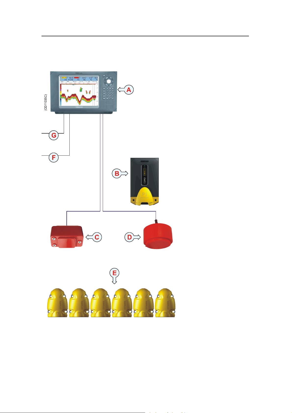
System diagram
(A) = Operator Unit
(B) = PI charger
(C) = Hydrophone
(provides communication
with the sensors)
(D) = Optional echo
sounder transducer.
Several types are
available.
(E) = Sensors mounted on
the net. Maximum six
sensors may be used
simultanously, and several
types are available.
(F) = Interfaces to
external sensors (serial
lines, NMEA format)
(G) = DC power input
2
851-165101 / Rev.A
Page 11

Introduction
Scope of supply
Main units
The standard Simrad PI44 catch monitoring system is comprised
of the following main units. All must be ordered separately.
Unit Order number
Operator Unit PI3--208872
Hydrophone, purse seine HYD--202711
Hydrophone, trawl HYD--205254
Hydrophone, portable HYD--202713
Paravane kit for portable hydrophone KIT--207284
+24 Vdc 5 A Power supply (230 vac) 290--076359
+13,2 Vdc 10 A Power supply (230 vac) 290--087521
Echo sounder transducers
The echo sounder transducers are optional. Note that only one
of the echo sounder transducers is required. Only the
transducers recommended by Simrad for use with the PI44
system are listed.
Transducer Order number
38/200 Combi C KSV--202192
38/200 Combi D KSV--203004
38/200 Combi W KSV--208845
50/200 Combi C KSV--202193
50/200 Combi D KSV--203005
Sensors
The Simrad PI44 catch monitoring system can operate with six
sensors simultanously. Several sensor types are available.
Sensor Order number
PI Bottom Contact sensor PI3--207642
851-165101 / Rev.A
PI Catch sensor PI3--207641
PI Depth sensor, 300 m PI3--207637
PI Depth sensor, 600 m PI3--207638
PI Depth sensor, 1000 m PI3--207639
PI Height sensor PI3--280002
PI Spread sensor PI3--206869
3
Page 12

Simrad PI44
Sensor Order number
PI Twin Spread sensor PI3--206896
PI Remote 1 sensor PI3--206870
PI Remote 2 sensor PI3--206871
PI Remote 3 sensor PI3--206872
PI Remote 4 sensor PI3--206885
PI Temperature sensor PI3--207640
Sensor chargers
In order to charge the PI44 sensor batteries, the following
charger is available.
Sensor Order number
PI Sensor charger LAD--207624
4
851-165101 / Rev.A
Page 13

Introduction
Supply conditions
The following supply conditions are applicable to standard
Simrad PI44 deliveries and associated optional equipment.
Equipment responsibility
The shipyard performing the installation and/or dealer becomes
fully responsible for the equipment upon receipt unless
otherwise stated in the contract. The duration of responsibility
includes:
• The period of time the equipment is stored locally before
installation.
• During the entire installation process.
• While commissioning the equipment.
• The period of time between commissioning and the final
acceptance of the equipment by the end user (normally the
owner of the vessel which the equipment has been installed).
The Simrad PI44 system guarantee period (as specified in the
contract) begins when the acceptance documents have been
signed unless other arrangements have been made in the
contract.
Receipt, unpacking and storage
Upon accepting shipment of the equipment, the shipyard and/or
the dealer should ensure that the delivery is complete and
inspect each shipping container for evidence of physical
damage. If this inspection reveals any indication of crushing,
dropping, immersion in water or any other form of damage, the
recipient should request that a representative from the company
used to transport the equipment be present during unpacking.
All equipment should be inspected for physical damage, i.e.
broken controls and indicators, dents, scratches etc. during
unpacking. If any damage to the equipment is discovered, the
recipient should notify both the transportation company and
Simrad so that Simrad can arrange for replacement or repair of
the damaged equipment.
Once unpacked, the equipment must be stored in a controlled
environment with an atmosphere free of corrosive agents,
excessive humidity or temperature extremes. The equipment
must be covered to protect it from dust and other forms of
contamination when stored.
851-165101 / Rev.A
5
Page 14

Simrad PI44
General installation requirements
Responsibility and approval
The Simrad PI44’s hydrophone and echo sounder i nstallation
must be approved on a case-by-case basis with regard to the
vessel’s national registry and corresponding maritime authority.
The shipowner and shipyard performing the installation are
responsible for obtaining installation approval.
Environmental requirements
All equipment, unless otherwise specified, must be protected
from temperature extremes and excessive humidity.
Compass deviation
Once the installation is complete, the vessel must be swung with
the PI44 system in both the operative and inoperative modes.
The shipowner and captain are responsible for updating the
deviation table accordingly with regard to the vessel’s national
registry and corresponding maritime authority.
Noise sources
The vessel’s hull, rudder(s) and propeller(s) should be
thoroughly inspected in dry dock prior to installation.
Roughness below the water-line deformities in the shell plating
and protruding obstacles can create underwater noise. These
sources of turbulence must be smoothed or removed as best as
possible. It is especially important that the propeller(s) is not
pitted or damaged.
Dry docking
Make sure that ample clearance under the hydrophone and e cho
sounder transducer is provided when dry docking the vessel.
Avoid locating supporting blocks or structures in the vicinity of
this equipment.
Note: The location of the hydrophone and echo sounder transducer
must be noted on the vessel’s docking plan for future reference.
Wiring
The cables from the wheelhouse to the hydrophone and echo
sounder transducer must be supported and protected along its
entire length using conduits and/or cable trays. Note that the
cables must not be installed in the vicinity of high-power
supplies and cables, antenna cables or other possible sources of
interferences.
6
851-165101 / Rev.A
Page 15

Introduction
Equipment handling
The units may be supplied as spare parts, or as parts of a
delivery.
Transportation
Unless otherwise stated in the accompanying documentation,
electronic, electro-mechanical and mechanical units supplied by
Simrad can be transported using all methods approved for
delicate equipment; (by road, rail, air or sea). The units are to be
transported in accordance with general or specific i nstructions
for the appropriate unit(s), using pallets, transport cases, or
carton boxes as appropriate.
Note: Special local restrictions concerning air transportation may be
applied to units containing certain types of batteries. The units
should be checked and the regulations investigated by the
packer/shipper before the unit is dispatched.
All local transportation must be carried out according to the
same specifications as for the initial delivery. In general, all
units must be handled with care. The carton or case containing
the equipment must be kept dry at all times, and must be
sheltered from the weather. It must not be subjected to shocks,
excessive vibration or other rough handling.
The carton or case will normally be marked with text or symbols
indicating which way up it is to be placed. Follow any
instructions given and ensure the case is always placed with its
“top” uppermost.
The carton or case must not be used for any purpose for which it
was not intended (step, table, etc.), and in the absence of other
information, no other cartons or cases must be stacked on top of
it.
Lifting
A heavy crate will normally be marked with its weight, and the
weights of other cartons or crates will normally be entered on
the packing list.
851-165101 / Rev.A
• Always check the weight of a crate before attempting to lift
it.
• Always use lifting apparatus that is certified for the load.
7
Page 16

Simrad PI44
Heavy units may be equipped with lifting lugs for transportation
by crane within the workshop or installation area. Before a crane
is used, check:
• The applicable weight certificate for the crane.
• The security of the lifting lugs.
Ensure that all available lifting lugs are used. Ensure the unit
remains under control during the operation to avoid damage to
the unit, equipment or personnel.
Heavy units may be transported using a fork-lift truck. Special
attention must then be paid to the position of the unit’s centre of
gravity. The units must be properly secured to the truck.
Initial preservation
When a system, a unit or a spare part has been delivered to the
customer, it may be subject to long-time storage prior to
installation and use. During this storage period, certain
specifications must be met.
The equipment must be preserved and stored in such a way that
it does not constitute any danger to health, environment or
personal injury.
Specific specifications are presented below.
→ For further information about storage, refer to page 12.
→ For further information about re-packing, refer to page 15.
→ For further information about temperature protection, refer to
page 17.
Preserving the original packing crate
1 The equipment must be stored in its original transportation
crate.
2 Ensure that the units are clearly separated in the shelves
and that each unit is easily identifiable.
3 The crate must not be used for any purpose for which it
was not intended (eg. work platform etc.).
4 The crates must not be placed on top of each other, unless
specific markings permit this.
5 The crates must not be placed directly on a dirt-floor.
6 Do not open the crate for inspection unless special
circumstances permit so.
- “Special circumstances” may be suspected damage to
the crate and its content, or inspections by civil
authorities.
8
851-165101 / Rev.A
Page 17

Introduction
- If any units are damaged, prepare an inspection report
stating the condition of the unit and actions taken.
Describe the damage and collect photographic evidence
if possible. Re-preserve the equipment.
- If the units are not damaged, check the humidity
absorbing material. If required, dry or replace the bags,
then repack the unit(s) according to the packing
instructions.
7 If the crate has been opened, make sure that is it closed
and sealed after the inspection.
- Use the original packing material as far as possible.
→ Refer to information on page 15.
Ambient temperature and humidity during
storage
1 The storage room/area must be dry, with a non-condensing
atmosphere. It must be free from corrosive agents.
2 The storage area’s mean temperature must not be lower
than -30°C, and not warmer than +70° C.
- If other limitations apply, the crates will be marked
accordingly.
Note: Transducers must not be stored in temperatures below -20°C, or
higher than +60°C.
3 The crate must not be exposed to moisture from fluid
leakages.
4 The crate must not be exposed to direct sunlight or
excessive warmth from heaters.
Shock and vibration during storage
1 The crate must not be subjected to excessive shock and
vibration.
851-165101 / Rev.A
ESD precautions during storage
→ Refer to the information on page 16.
If the unit contains normal batteries, these may have been
disconnected/isolated before the unit was packed. These must
only be reconnected before the installation starts. Units
containing batteries are marked.
9
Page 18

Simrad PI44
Caution: Units containing lithium or alkaline batteries must be
handled separately and with care. Such units are
marked accordingly. Do not attempt to recharge such
batteries, open them or dispose of them by
incineration. Refer to the applicable product data
sheets.
Inspection and unpacking
An inspection must be carried out immediately after the unit(s)
have arrived at their destination.
• Check all wooden or cardboard boxes, plastic bags and
pallets for physical damage. Look for signs of dropping,
immersion in water or other mishandling.
• If damage is detected externally, you will have to open the
packaging to check the contents.
- Request a representative of the carrier to be present while
the carton is opened, so any transportation damage can be
identified.
• If any units are damaged, prepare an inspection report stating
the condition of the unit and actions taken. Describe the
damage and collect photographic evidence if possible. Send
the inspection report to Simrad as soon as possible.
• If the units are not damaged, check the humidity absorbing
material. If required, dry or replace the bags, then repack the
unit(s) according to the packing instructions.
Inspection and unpacking: General procedure
Normal precautions for the handling, transportation and storage
of fragile electronic equipment must be undertaken.
Note: If the unit is not to be prepared for immediate use, you may
consider storing it unopened in its original packing material.
However, it may be useful to open the case to check its contents
for damage and retrieve any accompanying documentation.
10
• Check the carton before opening it to ensure it shows no
signs of dropping, immersion in water or other mishandling.
- If the carton shows signs of such damage, refer to the
paragraph covering Inspection on receipt.
851-165101 / Rev.A
Page 19

Introduction
• Place the carton on a stable work bench or on the floor with
the top of the carton uppermost.
• In the absence of other instructions, always open the top of
the carton first. The contents will normally have been
lowered into the carton from above, so this will usually be
the easiest route to follow.
- Care must be used when opening the carton to ensure the
contents are not damaged.
Caution: Do not use a knife to open cardboard cartons - the
contents may lie close to the surface, and may be
damaged by the blade.
• If the carton has been closed using staples, remove the staples
from the carton as you open it. This will reduce the
possibilities of scratch injury to yourself and damage to the
contents.
• If a wooden crate has been closed using screws, always
remove them using a screw-driver. Do not attempt to prise
the lid off with a crow-bar or similar.
• Once the carton is open, carefully remove all loose packing
and insulation material. Check for manuals and other
documents that may have been added to the carton during
packing, and put these to one side. Check also for special
tools, door keys etc.
Unpacking electronic and electro-mechanical
units
Caution: Beware of the dangers of Electro-Static Discharge
(ESD) both to yourself and to the equipment, when
handling electronic units and components. Refer to the
precautions starting on page 16.
Electronic and electro-mechanical units will normally be
wrapped in a clear plastic bag. Lift the unit, in its bag, out of the
carton and place it in a stable position on the floor/work bench.
Inspect the unit for damage before opening the plastic bag.
Note: Cables must never be used as carrying handles or lifting points.
851-165101 / Rev.A
11
Page 20

Simrad PI44
Note: Do not break the seal to open a circuit board package before the
board is to be used. If the board package is returned to the
manufacturers with the seal broken, the contents will be
assumed to have been used and the customer will be billed
accordingly.
Assuming all is well, open the bag and remove the unit.
Open the unit and check inside. Remove any packing and
desiccant material that may be inside.
Unpacking mechanical units
Mechanical units may be heavy. Using a suitably certified lifting
apparatus, lift the unit out of the crate and place it in a stable
position on the floor/work bench.
Inspect the unit for damage and remove any packing material
that may be inside the unit.
Unpacking transducers
Transducers may be supplied mounted to a hull unit (if any), or
packed separately. Crates are normally identified by the order
number and the serial number.
The transducer face must be protected by a rigid, padded cover
(e.g. a wooden box lined with foam rubber) all the time it is
exposed to the risk of physical damage.
Note: Once the units are unpacked, great care must be taken to ensure
that transducers and cabling are not exposed to any mechanical
stress.
Re-packaging
If the unit is not to be installed immediately, re-pack it in its
original packing material to prevent damage in the intervening
period.
12
→ Refer to the information on page 15.
Pre-installation storage
The equipment should be stored in its original transportation
crate until ready for installation. The crate must not be used for
any purpose for which it was not intended (eg. work platform
etc.).
851-165101 / Rev.A
Page 21

Introduction
Once unpacked, the equipment must be kept in a dry, non
condensing atmosphere, free from corrosive agents and isolated
from sources of vibration.
Note: Do not break the seal to open a circuit board package before the
board is to be used. If the board package is returned to the
manufacturers with the seal broken, the contents will be
assumed to have been used and the customer will be billed
accordingly.
The unit must be installed in its intended operating position as
soon as possible after unpacking.
If the unit contains normal batteries, these may have been
disconnected/isolated before the unit was packed. These must
then be reconnected during the installation procedure. Units
containing batteries are marked.
Caution: Units containing lithium or alkaline batteries must be
handled separately and with care. Such units are
marked accordingly. Do not attempt to recharge such
batteries, open them or dispose of them by
incineration. Refer to the applicable product data
sheets.
After use storage
If a unit is removed from its operating location and placed into
storage, it must be properly cleaned and prepared before
packing.
Cleaning cabinets
If a cabinet has been exposed to salt atmosphere while it was in
use, it must be thoroughly cleaned both i nternally and externally
to prevent corrosion.
• Wipe the cabinet externally using a damp cloth and a little
detergent. Do not use excessive amounts of water as the unit
may not be water tight. On completion, dry the unit
thoroughly.
851-165101 / Rev.A
• All surfaces must be inspected for signs of corrosion, eg.
flaking/bubbling paint, stains etc. Damaged or suspect areas
must be cleaned, prepared and preserved using the correct
preservation mediums for the unit. The mediums to be used
will usually be defined in the units’ maintenance manual.
13
Page 22

Simrad PI44
• Open the unit, and using a vacuum cleaner, remove all dust
etc. from the unit. Great care must be taken to ensure the
circuit boards and modules are not damaged in the process.
Mechanical units
If a mechanical unit may have been exposed to a salt
atmosphere while it was in use, it must be thoroughly cleaned
both internally and externally to prevent corrosion.
• If the construction materials and type of unit permits, wash
the unit using a high-pressure hose and copious amounts of
fresh water.
Examples:
- The lower parts of hull units (outside the hull)
- Subsea units
• Ensure that all traces of mud and marine growth are removed.
Use a wooden or plastic scraper to remove persistent growth,
barnacles etc. On completion, dry the unit thoroughly.
Caution: Do not use a high pressure hose in the vicinity of cables
or transducers. Do not use sharp or metal tools on a
transducer face.
• If the materials or type of unit prevents the use of a
high-pressure hose, wipe the unit using a cloth dampened
with water containing a little detergent.
Examples:
- The upper parts of hull units (inside the hull)
- Hydraulic systems
• Do not use excessive amounts of water as some components
on the unit may not be water tight. Wipe off the detergent
with a damp cloth, then dry the unit thoroughly.
• All surfaces must be inspected for signs of corrosion, eg.
flaking/bubbling paint, stains etc. Damaged or suspect areas
must be cleaned, prepared and preserved using the correct
preservation mediums. The mediums to be used will
normally be defined in the unit’s maintenance manual.
14
Cables
Wipe clean all exposed cables, and check for damage. If a cable
shows signs of wear or ageing, contact Simrad for advice.
851-165101 / Rev.A
Page 23

Introduction
Internal batteries
If the unit contains batteries, these may discharge slowly during
storage. If the unit is to be stored for an extended period,
disconnect or remove all internal batteries.
A suitable piece of insulating material can be placed between
the battery and the electrical contacts to prevent electrical
discharge. The battery can then remain in the unit, reducing the
risk of it being misplaced during the storage period.
Caution: Units containing lithium or alkaline batteries must be
handled separately and with care. Such units are
marked accordingly. Do not attempt to recharge such
batteries, open them or dispose of them by
incineration. Refer to the applicable product data
sheets.
Dehumidifier
Place a suitably sized bag of desiccant material (silica gel or
similar) into the unit to keep the electronic components as dry as
possible.
Coatings
Spray the unit externally with a corrosion inhibitor (e.g. a light
oil) before packing.
Re-packing
The unit should be stored and transported in its original packing
material and/or crate. In the event that this material is not
available, proceed as follows:
• Small units must be protected from damp by being placed
within a plastic bag at least 0.15 mm thick. An appropriate
quantity of desiccant material should be placed inside this
bag, and the bag sealed. The sealed unit must then be placed
in an appropriate carton or crate, and supported in the
container by appropriate shock-absorbing insulation
(polystyrene foam chips etc.).
851-165101 / Rev.A
• Large units must be placed in a suitable cardboard box or
wooden crate. The unit must be protected against physical
damage by means of shock-absorbing insulation mats. The
box must be clearly marked with its contents, and must be
stored in a dry and dust-free area.
15
Page 24

Simrad PI44
ESD precautions
Electro-Static Discharge (ESD) is the transfer of an electrostatic
charge between two bodies at different electrostatic potentials,
caused either by direct contact or induction by an electrostatic
field.
The passing of a charge through an electronic device can cause
localised overheating, and it can also “puncture” insulating
layers within the structure of the device. This may deposit a
conductive residue of the vaporised metal on the device, and
thus create a short circuit. This may result in a catastrophic
failure, or degraded performance of the device.
Sensitive electronic equipment must be transported and stored in
protective packing bags, boxes and cabinets. The equipment
must NOT be transported or stored close to strong electrostatic,
electro-magnetic or radioactive fields.
If it is necessary to open and touch the electronics inside the
boxes/cabinets, then the following precautions MUST be taken:
• The working area must be covered by an approved
conductive service mat that has a resistance of between 50kΩ
and2MΩ, and is connected directly to a reliable earth point
via its earthing cord.
• The service personnel involved must wear a wrist-band in
direct contact with the skin, connected to the service mat.
• Printed circuit boards and other components should be placed
on the conductive service mat during installation,
maintenance etc.
Caution: If, for any reason, it is necessary to move the circuit
board or components from the conductive service mat,
they must be placed in an approved anti-static
transportation container (e.g. static shielding bag)
before transportation.
• During installation and servicing, all electrical equipment
(soldering irons, test equipment etc.) must be earthed.
16
851-165101 / Rev.A
Page 25

Temperature protection
If the unit must be protected against extremes of temperature,
the carton/crate must be lined on all walls, base and lid with
5 cm thick polyurethane or polystyrene foam.
These units will be identified as delicate i n the applicable
documentation.
The package must then be clearly marked:
Note: Must not be transported or stored in temperatures
below -5 degrees Celsius.
Other units can normally be stored in temperatures
between -30° C and +70° C, refer t o the system’s technical
specifications for details.
Introduction
Transducers must not be stored in temperatures below -20°C
and above +60°C.
851-165101 / Rev.A
17
Page 26

Simrad PI44
2 TRANSDUCER INSTALLATION
Purpose
Due to the fact that several transducer types may be used with
the PI44 system, you will need to read the installation manual
for the chosen transducer. The information provided in this
chapter will only provide general information. Refer to the
installation manuals provided with the transducers for more
specific information.
The PI44 can be used with maximum two transducers
simultanously, one low frequency (38 or 50 kHz) and one high
frequency (200 kHz). We recommend that any one of the
following transducers are used:
• Simrad 38-200 Combi C (dual frequency)
• Simrad 38-200 Combi D (dual frequency)
• Simrad 38-200 Combi W (dual frequency, wide beam)
Other transducers may also be used. Budget transducers
designed for leasure crafts are however not recommended for
professional fishery applications.
Topics
→ Transducer location, page 19
→ External mounting (Combi C and D), page 23
→ Blister mounting (Combi W), page 28
→ Cable glands, page 35
→ Cable in steel conduit, page 39
→ Handling and maintenance, page 40
→ Approved anti-fouling paints, page 41
Related topics
→ Purse seine hydrophone installation, page 42
→ Trawl hydrophone installation, page 79
→ Portable hydrophone, page 120
18
851-165101 / Rev.A
Page 27

Transducer installation
Transducer location
General
A single answer to the question where to locate the transducer
cannot be given. It depends very much on the vessel’s
construction. However, there are some important guide lines.
Go deep
The upper water layers of the sea contain a myriad of small air
bubbles created by the breaking waves. In heavy seas the
uppermost 5 to 10 metres may be air-filled, with the highest
concentrations near the surface. Air bubbles absorb and reflect
the sound energy, and may in worst cases block the sound
transmission totally. Therefore, mount the transducer at a deep
position on the hull.
Consider the situation when the vessel is unloaded, and when it
is pitching in heavy seas. The transducer must never be lifted
free of the water surface. Not only will the sound transmission
be blocked, but the transducer may be damaged by slamming
against the sea surface.
Another reason to go deep is cavitation in front of high power
transducers. Cavitation is the formation of small bubbles in the
water due to the resulting local pressure becoming negative
during parts of the acoustic pressure cycles. The cavitation
threshold increases with the hydrostatic pressure.
Vessel heave
Heave is the up and down movement of the vessel. It disturbs
the echo traces in the echogram, so that a flat bottom is
displayed as a wave. A transducer location in the middle of the
vessel minimises the influence of vessel roll and pitch.
Noises from protruding objects on the hull
Objects protruding from the hull, such as zinc anodes, sonar
transducers or even the vessel’s keel, generate turbulence and
flow noise. Also holes and pipe outlets are noise sources. They
may act as resonant cavities amplifying the f low noise at certain
frequencies. Do not place an echo sounder transducer in the
vicinity of such objects, and especially not close behind them.
For the same reason, it is very important that the hull area
around the transducer face is as smooth and level as possible.
Even traces of sealing compound, sharp edges, protruding bolts
or bolt holes without filling compound will create noise.
851-165101 / Rev.A
19
Page 28
Simrad PI44
Boundary water layer
When the vessel forces its way through the sea, the friction
between the hull and the water creates a boundary layer. The
thickness of the boundary layer depends upon vessel speed and
the roughness of the hull. Objects protruding from the hull, and
dents in the hull, disturb the flow and increase the thickness of
the boundary layer. The flow in this boundary layer may be
laminar or turbulent. A laminar flow is a nicely ordered, parallel
movement of the water. A turbulent flow has a disorderly
pattern, full of eddies. The boundary layer increases in thickness
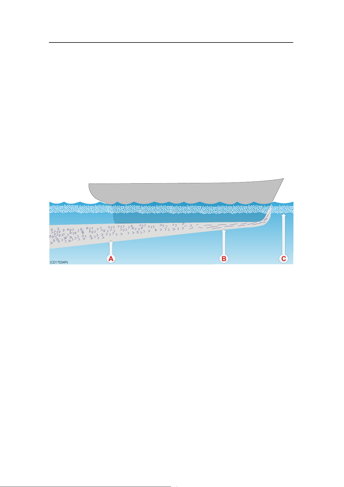
when the flow goes from laminar to turbulent. The figure below
illustrates the boundary layer of a vessel moving through the
water.
Boundary water layers:
(A) = Turbulent flow
(B) = Laminar flow
(C) = Air bubbles in the water
Furthermore, air bubbles in the sea water are pressed down
below the hull and mixed into the boundary layer. The boundary
layer is thin underneath the forward part of the vessel, and
increases in thickness as it moves towards aft. If the sides of the
hull are steep, some of the air bubbles in the boundary layer may
escape to the sea surface along the vessel sides. It is our
experience that a wide and flat bottom, with a rising angle less
than around 13 degrees, is prone to giving air problems for the
transducer. In any case a transducer location in the forward part
of the hull is preferred in order to minimise the influence of the
boundary layer.
20
851-165101 / Rev.A
Page 29

Transducer installation
Propeller noise
The propulsion propeller is the dominant noise source on most
fishing vessels, research vessels, merchant vessels and pleasure
crafts. The noise is transmitted through the sea water. For this
reason, the transducer should be placed far away from the
propeller, which means on the fore part of the hull. Positions
outside the direct line of sight from the propeller are favourable.
On small vessels with short distances it is advised to mount the
transducer on that side of the keel where the propeller blades
move upwards, because the propeller cavitation is strongest on
the other side. The cavitation starts most easily when the water
flows in the same direction as the propeller blade, and that is to
some degree the case at that side of the keel where the propeller
blades move downwards.
Bow thruster propellers are extremely noisy. When in operation,
the noise and cavitation bubbles make the echo sounder useless,
almost no matter where the transducer is installed. And when
not in operation, the tunnel creates turbulence, and if the vessel
is pitching, the tunnel may be filled with air or aerated water in
the upper position and release this in the lower position.
Therefore, an echo sounder transducer should be placed well
away from the bow thruster.
851-165101 / Rev.A
21
Page 30
Simrad PI44
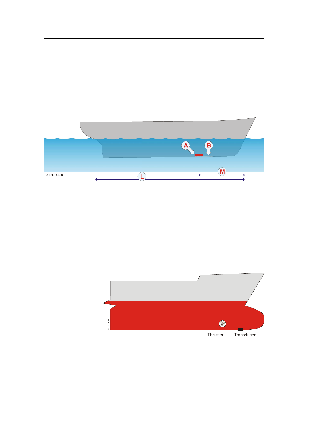
Summary and general recommendation
Some of the above guide lines are conflicting, and each case has
to be treated individually in order to find the best compromise.
Generally the propeller noise is the dominant factor, and a
recommended transducer location is in the fore part of the hull,
with maximum distance from the bow equal to one third of the
total length of the hull at the water line.
General recommendation for transducer location:
(A) = Transducer
(B) = Angle 1 - 2 degrees
(L) = Hull length at water line
(M) = Maximum 1/3 of the hull length at water line (L)
If the vessel hull has a bulbous bow, this may well be a good
transducer location, but also here must be taken into
consideration the flow pattern of the aerated water. Often the
foremost part of the bulb is preferable.
22
851-165101 / Rev.A
Page 31

Transducer installation
External mounting
This transducer has a streamlined housing, and it is designed for
installation outside the hull.
This transducer is mainly used on smaller vessels. A location
approximately 0.5 m aside from the keel may be adequate for
the passage of water between the keel and the transducer. The
figures illustrate external mounting of transducers on steel hulls
and on wood or polyester hulls respectively.
Inclination of the transducer face
Incline the transducer face approximately 1-2 degrees (D), so
that the flowing water meets it directly. This assures laminar
water flow. Mounting screws must not be extruding from the
transducer, and the space around the screws must be filled with
a compound (C) and/or a locking ring.
Smooth surface
Ensure that the surface of the transducer face, the hull plating
and putty around the transducer is as even and smooth as
possible. Obstructions on these surfaces will create problems
with turbulant flow.
851-165101 / Rev.A
23
Page 32

Simrad PI44
Steel hull
A fairing (A), made by the shipyard, is placed between the
transducer and the hull. It is required in order to adapt for the
deadrise angle of the hull, and it will also house a cable service
loop (B). The fairing can be made of wood or steel, and should
have the same outline dimensions as the transducer. Remember
to create an air outlet (E) on the fairing, and to fill the bolt holes
with a filling compound to ensure a smooth transducer surface.
24
(A) = Fairing (1) = Steel conduit
(B) = Cable service loop (2) = Stuffing tube
(C) = Filling compound (3) = Washer
(D) = 1-2 degrees inclination (4) = Rubber gasket
(E) = Air outlet (5) = Packing nipple
(F) = Forward
(I) = Threaded rod with nuts and washers, or bolt
851-165101 / Rev.A
Page 33
Transducer installation
Wood or polyester hull
A fairing (A), made by the shipyard, is placed between the
transducer and the hull. It is required in order to adapt for the
deadrise angle of the hull, and will also house a cable service
loop (B). The fairing is made from wood, polyester or steel, and
should have the same outline dimensions as the transducer. Use
tarred felt (H) between th fairing and the hull. Remember to
create an air outlet (E) on the fairing, and to fill the bolt holes
with a filling compound to ensure a smooth transducer surface.
851-165101 / Rev.A
(A) = Fairing (1) = Steel conduit
(B) = Cable service loop (2) = Stuffing tube
(C) = Filling compound (3) = Washer
(D) = 1-2 degrees inclination (4) = Rubber gasket
(E) = Air outlet (5) = Packing nipple
(F) = Forward
(G) = Shim (wood)
(H) = Tarred felt
(I) = Threaded rod with nuts and washers
25
Page 34

Simrad PI44
Flat hull
If the vessel’s hull is flat you do not need a fairing. The
transducer is then be bolted directly to the hull using two bronze
or stainless steel bolts (I) and a cable bushing. Note that the
cable bushing must be mounted with proper gaskets (4) under
and over the hull, as well as sealing compound (J) around the its
body. Also, fill the bolt holes with a filling compound to ensure
a smooth transducer surface.
(C) = Filling compound (3) = Washer
(F) = Forward (4) = Rubber gaskets
(I) = Threaded rod with nuts and washers
(J) = Sealing compound
26
851-165101 / Rev.A
Page 35

Transducer installation
Longitudinal angle
On deplacement hulls, the transducer (A) must be mounted in an
angle of 5 to 8 degrees (B) in relation to the keel (C).
With a planing hull, this angle must be 0 degrees.
(A) = Transducer
(B)=5to8°ondeplacementhulls,0°onplaninghulls
(C) = Keel
(F) = Forward
851-165101 / Rev.A
27
Page 36

Simrad PI44
Transducer blister
With a transducer with circular housing, one recommended
installation method is by using a blister.
The transducer blister must be designed and manufactured by
the installation shipyard to fit the vessel’s sixe and hull shape.
Mounting and clamping rings
Circular transducers may be provided with mounting and
clamping rings, or with drawings to allow for local production
of these. The mounting ring is welded to the hole in the
transducer blister, while the clamping ring fits around the edge
of the transducer body. Bolts through the clamping ring into the
mounting ring will then secure the transducer between them.
Note that several transducers use direction guides to allow
correct mounting.
Inclination of the transducer face
Incline the transducer face approximately 1-2 degrees, so that
the flowing water meets it directly. This assures laminar water
flow.
Smooth surface
Mounting screws or bolts must not be extruding from the
transducer blister. Ensure that the surface of the transducer face,
the blister, the hull plating and putty around the transducer is as
even and smooth as possible. Obstructions on these surfaces will
create problems with turbulant flow.
Horizontal support bar
Large diameter transducers must be fitted with a horizontal
support bar. This bar can be secured to the mounting ring using
threaded rods.
28
851-165101 / Rev.A
Page 37

Transducer installation
Example: Large transducer
The illustration below shows a typical transducer blister
designed for a large transducer. Note that due to the physical
size of the transducer, a U-shaped support bar (E) is used to
support the transducer.
(A) = Streamlined blister (F) = Forward
(B) = Stiffening rib (G) = Cable service loop
(C) = Drainage holes (H) = Stuffing tube
(D) = 1-2 degrees angle (I) = Minimum 400 mm
(E) = U-shaped support bar (J) = Rounded corners
(K) = Air outlet
851-165101 / Rev.A
29
Page 38

Simrad PI44
Example: Small transducer
The illustration below shows a typical transducer blister
designed for a small transducer. The same blister design
principles as for a large transducer apply.
30
(A) = Streamlined blister (E) = Air outlet
(B) = Mounting ring (F) = Forward
(C) = Clamping ring (G) = Transducer cable
(D) = Guide
Note that the transducer cable must be provided with a cable
loop inside the blister. Observe the vertical forward edge of the
blister. This will guide the water to each side of the blister.
851-165101 / Rev.A
Page 39
Transducer installation
Common guidelines
The best performance is obtained with a blister height of 40 cm
or more. A streamlined shape and rounded edges reduce the
flow noise. A vertical leading edge or front will guide the
aerated water to the sides of the blister. The orientation of the
blister should follow the water flow.
The interior of the blister must be filled with sea water. Use
drainage holes in the bottom and an air outlet on the top. The
water pressure behind the transducer will then compensate for
the outside pressure during vessel movements in rough sea.
Large diameter transducers must be fitted with a horizontal
U-shaped support bar. This bar can then be secured to the
mounting ring using threaded rods.
The transducer cable penetrates the hull in a stuffing tube. Leave
an adequate loop of the cable behind the transducer for easy
mounting or removal of the transducer.
Toe-in
On a conventional hull shape, without a bulb, the front of the
blister should have a few degrees toe-in towards the bow.
(A) = Keel
(B) = Blister
(C) = Toe-in angle 5 to 8 degrees
851-165101 / Rev.A
31
Page 40
Simrad PI44
Physical location
The blister is placed on one of the sides of the hull, and the
distance from the keel is a trade off between a close distance
giving a turbulent flow of water in a narrow passage, and a large
distance bringing the transducer higher up and also more
affected by vessel roll. Normally a distance of approximately
1 m is a good compromise.
Observe the horizontal and vertical distances (X and Y) between
the keel and the transducer blister. On a medium sized vessel,
the horizontal distance (X) should be approximately 1 meter.
The vertical distance (Y) must in general be as small as possible.
This is important to prevent the keel from shadowing the
transducer beam in shallow waters.
32
(A) = Keel
(B) = Transducer blister
(X) = Horizontal distance between keel and blister
(Y) = Vertical distance between the blister surface and the keel
851-165101 / Rev.A
Page 41

Transducer installation
Box keel
Vessels with a box keel may use this for transducer installation.
The box keel is already the deepest part of the vessel. If the box
keel is too narrow to accommodate the transducer, it can be
widened, either symmetrically or to one side only. In the last
case the installation could also be described as a blister merged
into the keel.
Mounting and clamping rings
Circular transducers may be provided with mounting and
clamping rings, or with drawings to allow for local production
of these. The mounting ring is welded to the hole in the box
keel, while the clamping ring fits around the edge of the
transducer body. Bolts through the clamping ring into the
mounting ring will then secure the transducer between them.
Note that several transducers use direction guides to allow
correct mounting.
Inclination of the transducer face
If possible, incline the transducer face approximately 1-2
degrees, so that the flowing water meets it directly. This assures
laminar water flow.
Smooth surface
Mounting screws or bolts must not be extruding from the box
keel. Ensure that the surface of the transducer face, the box, the
hull plating and putty around the transducer is as even and
smooth as possible. Obstructions on these surfaces will create
problems with turbulant flow.
Horizontal support bar
Large diameter transducers must be fitted with a horizontal
support bar. This bar can be secured to the mounting ring using
threaded rods.
851-165101 / Rev.A
33
Page 42
Simrad PI44
Example
The figure below illustrates a symmetrical box keel installation.
(A) = Box keel (D) = Cable in steel conduit
(B) = U-shaped support bar (E) = Cable service loop
(C) = Stuffing tube
34
851-165101 / Rev.A
Page 43

Transducer installation
Cable glands
The transducer cable must pass through the hull using approved
cable glands for the type of vessel in question.
A steel cable gland is normally used on professional vessels
with steel hulls. A bronze cable gland can be delivered as an
option for vessels with wood or fibreglass construction. Vessel
not to be classified can as an option use a cable gland made of
plastic.
Note: Simrad strongly recommends that a length of conduit is fitted
around transducer cable glands made of steel or bronze and
extended over the water-line inside the vessel. This precaution
reduces the danger of flooding in the event of gland failure and
transducers installed in this manner are also easier to replace.
Some vessels may experience difficulties finding suitable areas
of the hull for mounting transducer cable glands due to existing
water tanks, concrete ballast or other obstacles. A possible
solution in such cases is to run the transducer cables in a steel
conduit aft along the hull until a suitable cable gland location is
available. The respective cable gland can then be installed as
described in the following instructions.
Note: Simrad takes no responsibility for the correct installation of
cable glands, associated hull modifications and/or structural
support of transducer cable penetration. These activities are
subject to individual approval by the respective classification
society for the vessel in question.
Order numbers
Steel hull cable gland kit: 599-202216
Wood/GRP hull cable gland kit: 119-038200
Small vessel cable gland kit: 599-202182
851-165101 / Rev.A
35
Page 44

Simrad PI44
Cable gland installation for steel hulls
This cable gland kit is designed for steel vessels. It must be
welded to the hull plates.
(A) = Steel conduit
(B) = Stuffing tube, DNV
approved carbon steel st52.3
(C) = Washers, 24 x 8 x 2 mm
(D) = Rubber gasket
(E) = Packing nipple. Make
sure that you do not damage the
transducer cable by tightening
the packing nipple too hard!
(F) = Cable to the echo
sounder (or a junction box)
The gland gland kit includes all
of the necessary parts needed to
install the unit excluding
screws.
Simrad recommends that a one
inch steel conduit (that the
transducer cable will be run
through) with an inside
threaded diameter of
three-quarter inches is welded
to the gland’s stuffing tube. The
conduit must extend to above
the vessel’s water line.
36
851-165101 / Rev.A
Page 45

Transducer installation
Gland installation for wood or GRP hulled vessels
A bronze cable gland kit is available for wood and GRP vessels.
(A) = Packing nipple. Make
sure that you do not damage the
transducer cable by tightening
the packing nipple too hard!
(B) = Washers
(C) = Rubber gaskets
(D) = Hole diameter 28 mm
(E) = Steel conduit
(F) = Cable to the echo
sounder (or a junction box)
The gland gland kit includes all
of the necessary parts needed to
install the unit excluding
screws.
Simrad recommends that a one
inch steel conduit (that the
transducer cable will be run
through) with an inside
threaded diameter of
three-quarter inches is attached
to the gland’s packing nipple.
This connection must be
watertight, and the conduit must
extend to above the vessel’s
water line.
851-165101 / Rev.A
37
Page 46

Simrad PI44
Cable gland installation for smaller vessels
This cable glands made of plastic is designed for those smaller
vessels that do not need to be classified.
(A) = Packing nut (bronze).
Ensure that you do not to
damage the transducer cable by
tightening the packing nut too
hard!
(B) = Rubber gasket
(C) = Plastic disk
(D) = Rubber gasket
(E) = Stuffing tube
(F) = Backing nut (bronze)
(G) = Backing washer (plastic)
(H) = O-ring 42.5 x 3.0 N
(I) = O-ring 39.5 x 3.0 N
(J) = Cable to the echo sounder
(or a junction box)
Stuffing tube hole diameter: 36 mm ±1.5 mm.
Apply ample amount of sealant between the backing washer (H)
and the hull plate.
The cable gland kit contains all the listed parts, except the
sealant.
Note: The two O-rings must be clean, in good condition and free of cuts
or other defects which could affect their water-tight integrity.
Splicing
If you need to cut the transducer cable, you must splice it
correctly.
Note: DO NOT solder the wires together with only electrical tape for
insulation, as this will result in electrical noise and reduced
operational performance.
To splice the cable, use a metal junction box. The chassis of the
junction box must be grounded, but the cable shielding must
NOT be connected to the junction box ground.
38
851-165101 / Rev.A
Page 47

Transducer installation
Cable in steel conduit
It is strongly recommended to lay a steel conduit from the
transducer’s cable gland to the echo sounder transceiver, and to
pull the transducer cable through this conduit. There are two
reasons for this.
• First, it will make it easier at a later stage to replace the
transducer.
• Second, noise and i nterference from other electrical
equipment is greatly reduced.
With a steel conduit the installation will satisfy the EU
regulations for EMC interference. Without a steel conduit, there
is a risk of reduced echo sounder performance.
The steel conduit must be unbroken and watertight from the
transducer to above the water line. From there, the cable can be
pulled further, or a junction box can be installed to facilitate
further connections. Note that the steel conduit must act as a
continuous electrical screen all the way. To ensure proper
shieklding, the conduit must be electrically connected to the
echo sounder transceiver chassis.
Steel conduit dimensions:
• minimum 35 mm inner diameter
• minimum 6 mm wall thickness (4.5 mm if galvanised).
If two or more transducers are installed close to each other it is
possible to pull their cables in the same steel conduit, provided
the conduit diameter is increased accordingly. However, for easy
replacement it is recommended that each transducer has its own
steel conduit.
851-165101 / Rev.A
39
Page 48

Simrad PI44
Handling and maintenance
Do not lift the transducer by the cable.
Some transducers are delivered with a cover plate on the face
for protection during transport. Let this plate stay on as long as
possible, but do not forget to remove it before the vessel goes
into the sea.
An anti-fouling paint may be applied to the transducer face.
Because some paint types may be aggressive to the polyurethane
in the transducer face, please consult Simrad’s list of approved
paints on the next page.
Note: Arctic tanks have acoustic windows made of polycarbonate.
These must neither be painted nor cleaned with chemicals.
During dry docking of the vessel, the transducer face may be
cleaned for shells and other marine fouling. Be careful not to
make cuts in the transducer face. Use a piece of wood or a very
fine grade emery paper.
40
851-165101 / Rev.A
Page 49

Transducer installation
Approved anti-fouling paints
This is Simrad’s list of approved antifouling paints on
polyurethane transducer housing.
From Jotun Paints, Sandefjord Norway:
• Antifouling Seamate HB 33
• Antifouling Seamate HB 66
• Antifouling Seamate HB 99
• Racing
• Non-stop
From International Paints:
• Intersleek tie coat + 425 FCS
- BXA386/BXA390/BXA391 Grey
- HKA563/HKA570/HKA571 Yellow
Mix BXA386, BXA390 and BXA391 first, then apply. When
dry, mix HKA563, HKA570 and HKA571, apply.
From Hempel IFA Coatings AS:
• Hempel A/F Classic 76550
From Jotun-Henry Clark Ltd:
• Anti-fouling Seaguardian
From International Marine Coatings:
• Intersmooth 360 Ecoloflex SPC
• Micron Ekstra
Note: Refer to the manufacturer’s documentation and data sheets for a
complete procedure.
851-165101 / Rev.A
41
Page 50

Simrad PI44
3 PURSE SEINE HYDROPHONE
Purpose
The purpose of this chapter is to provide general guidelines for
the installation of the PI44 hydrophone for purse seining.
Note: If your vessel shall be fitted for trawl operations, DO NOT
install the hydrophone(s) as explained in this chapter!
Order numbers
Purse hydrophone, complete: HYD-202711
Purse hydrophone, without cable gland: HYD-205075
Topics
→ Precautions, page 43
→ Considerations, page 44
→ Pre-installation checklist, page 48
→ Location, page 50
→ Coverage area, orientation and tilt, page 51
→ Mounting arrangement, page 54
→ Dual hydrophones, page 57
→ Hydrophone protection, page 59
→ Hydrophone cable, page 62
→ Installation drawings, page 67
42
851-165101 / Rev.A
Page 51

Purse seine hydrophone installation
Installation precautions
Caution: The following precautions must be observed. Failure to
do so can result in damage to the hydrophone which
may render the PI44 catch monitoring system
inoperative.
1 Observe the maximum allowable torque warning of 5 Nm
when tightening the hydrophone studs.
2 Use only M8x30 socket countersunk head screws for
mounting the hydrophone.
3 Secure threaded hydrophone hardware with Loctitet 270
or the equivalent.
4 Do not paint the hydrophone.
5 Do not sand-blast, power or steam wash the hydrophone.
6 Do not scrape the hydrophone with metal or other hard
objects that may damage the polyurethane sheathing.
7 Do not strike the hydrophone.
8 Do not expose the hydrophone to harsh chemicals.
9 Do not perform hot work in the vicinity of the
hydrophone.
10 Do not lift the hydrophone by its cable.
851-165101 / Rev.A
43
Page 52

Simrad PI44
Considerations
Correct installation of the PI44 hydrophone is vital to the
system’s performance. Several variables must be taken into
consideration, the most important of which is the vessel’s
construction. This guide is for use in selecting the best location
for the hydrophone and includes a brief description of areas to
be avoided.
Note: Simrad strongly suggests that this information is read
thoroughly, and that the instructions are understood and
followed. Proper hydrophone placement is difficult to achieve,
but essential for correct system operation.
Depth
Water just below the sea surface contains a myriad of small air
bubbles created by the turbulence of breaking waves. The first
five to ten metres may be heavily saturated in moderate seas
with the greatest concentration and largest bubbles closest the
surface. Air bubbles disrupt sound waves in water. The degree
to which they absorb and reflect such energy vary, but in some
cases they can block hydrophone reception. It is therefore
recommended to mount the unit as deep as possible.
Pounding danger
When a vessel is in ballast and pitching in heavy seas, it is
important that the hydrophone is not lifted out of the water.
Should a vessel pound so heavily that the hydrophone be
exposed, sound reception will be interrupted and the unit may
be damaged on impact.
The boundary layer
The flow of water in the immediate vicinity of the hull of a
moving vessel is known as a boundary layer. This flow is
responsible for underwater noise that can disturb hydrophone
reception and its thickness is contingent on a vessel’s:
• Hull form
• Size and number of underwater protrusions
• Velocity
• Hull roughness
The boundary layer is thin (laminar flow) near the vessel’s bow
and becomes thicker (turbulent flow) as it moves aft. Laminar
flow is smooth with streamlines approximately parallel to the
hull and contributes relatively little to noise created by flow.
Conversely, turbulent flow is more disorderly and in turn
contributes to a greater extent.
44
851-165101 / Rev.A
Page 53

Purse seine hydrophone installation
Boundary water layers:
(A) = Turbulent flow
(B) = Laminar flow
(C) = Air bubbles in the water
Air bubbles may also be introduced into the boundary layer. If
the vessel’s hull has little flare and is relatively narrow, bubbles
may escape to the sea surface without incident. On the other
hand a wide, flat hull with minimal deadrise is prone to trapping
air bubbles no matter how little flare it has. Regardless of a
vessel’s hull form, hydrophones are generally recommended to
be installed on the forward part of the hull to minimising the
influence of both turbulence and air bubbles.
Bulbous bow
The bulbous bow may be an acceptable hydrophone location.
Should this position be chosen, the foremost part of the bulb is
often best, but also the m ost susceptible to pounding.
851-165101 / Rev.A
Recommended location of the transducer on a bulbous hull:
(A) = Thruster
(B) = Hydrophone location
45
Page 54

Simrad PI44
Propeller noise
A vessel’s main propeller is the dominant source of underwater
acoustic noise. When ever possible, hydrophone(s) should be
located as far a way as possible from the main propeller and
never closer than ten meters. Hydrophone(s) should not be
mounted in the direct acoustic path (line-of-sight) of the main
propeller unless absolutely necessary.
The primary cause of propeller noise is cavitation (small
bubbles generated by the partial vacuum created by the blades as
they pass through the water). The resulting underwater acoustic
noise from cavitation is normally weakest on the side of the
vessel were the propeller blades rotate toward the surface and
most pronounced on the side were they rotate toward the
bottom. Most vessels have clock-wise rotating propellers
resulting in their port sides being less effected by cavitation
induced noise than their starboard.
To minimise the negative effect of cavitation noise on
hydrophone performance, installation is generally recommended
as follows:
• Single hydrophone - if only one hydrophone is to be
installed on a vessel with a clock-wise rotating propeller, it
should be located on the port side of the hull.
• Dual hydrophones - if two hydrophones are to be installed,
they should be placed on either side of the vessel’s keel.
When in doubt about the best fore-and-aft location for
hydrophones, they can be placed at different distances from
the bow (for example the port hydrophone can be a little
further aft than the starboard, approximately three to five
meters for a thirty-five meter vessel). When trawling in both
deep and shallow water the hydrophones should also be tilted
differently with respect to each other. The hydrophone that is
closest to the propeller should have the greatest tilt and be
located on the port side of the hull for a vessels with
clock-wise rotating propellers.
Bow/sternthruster noise
46
Bow and sternthruster operation may severely effect
hydrophone reception. Hydrophone installation closer than four
meters to either is strongly discouraged.
851-165101 / Rev.A
Page 55

Purse seine hydrophone installation
When not in operation, bow/sternthruster tunnels create
turbulence and hence underwater noise when a vessel is under
way. Also, as a vessel pitches in heavy weather, thruster tunnels
may fill with air or aerated water which can disturb hydrophone
reception when released. Hydrophone installation should take
into regard the noise and down stream disturbances found
around and aft of thrusters.
Note: Hydrophone installation must take into regard the noise and
down stream disturbances found around and aft of thrusters.
Noise from protruding objects and other sources
The primary sources of underwater disturbance (other than a
vessel’s main propeller and bow/sternthruster) that affect
hydrophone reception are:
• Main or bilge keels
• Zinc anodes
• Cooling elements protruding from the hull
• Equipment such as sonar hydrophones and pitot tubes
• Sea chests
• Overboard discharges
• Dents in the hull
All appendages to the hull, indentations and pipe outlets are
potential sources of underwater noise. They may act as resonant
cavities amplifying noise at certain frequencies, create cavitation
or turbulence. Hydrophones should not be located in the vicinity
of such objects and especially not immediately aft of them.
Minimum distance to sonar and echo sounder
transducers
To avoid interference, PI44 hydrophone(s) must be installed as
far away as possible from other sources of underwater acoustical
energy such as active sonars and echo sounder transducers.
Hydrophones should be placed at least two meters from such
equipment when ever possible and distances of less than one
meter avoided. Hydrophones installed in close proximity to
underwater acoustical sources should be located as far aft as
possible from them, and most importantly, not be subjected to
direct (frontal) transmission from such equipment.
Drop keel
In the event the vessel is equipped with a drop keel, the
hydrophones should be mounted aft of it. The choice between
installing a one, or two hydrophone system should be based on
the same horizontal and vertical coverage requirements for
vessels operating under similar conditions with fixed keels.
851-165101 / Rev.A
47
Page 56

Simrad PI44
Pre-installation check-list
Choosing the optimal locations for hydrophones is not always
easy, but decisions made at this phase of the installation process
are critical to future system performance. Determining the best
configuration for a given vessel often involves a compromise
between contradicting requirements.
To aid in this evaluation process Simrad recommends that this
installation manual be read thoroughly and the following check
list completed before deciding on a final installation strategy for
the PI44 system.
1 Hydrophones do not have a direct line-of-sight to the main
propeller and are placed where the vessel’s hull protects
them from underwater acoustic noise as well as possible.
2 Hydrophones must always have an unobstructed
line-of-sight to the sensors attached to the gear for the
system to operate properly.
3 The distance from the main propeller to the hydrophones
should be greater than ten meters. A separation of less
than ten meters can reduce system range significantly.
4 If thrusters are installed, hydrophones should be located at
least four meters from them.
5 Avoid locating hydrophones behind thrusters where air
bubbles from their tunnels generated when the vessel
pounds can block sensor signals.
6 Hydrophone should not be placed forward of other
underwater acoustic equipment and preferably behind it as
far away as possible, distances of less than one meter
should be avoided.
7 There should never be possible sources of underwater
acoustic noise placed in front of hydrophones.
8 Remember that hydrophones are to be mounted with their
long axis up (in the vertical plane).
9 Hydrophones installed in blisters should be located away
from the vessel’s keel and as deep as possible on the hull.
10 Hydrophones installed in shoes along the vessel’s keel
should be mounted as deeply as possible.
48
11 Hydrophone cables that are run in conduit along the
outside of the vessels hull should be arranged as to
produce the least amount of underwater acoustic noise as
possible.
12 Blisters and shoes should be as streamlined as possible and
have all of their corners rounded to minimize the
generation of underwater acoustic noise.
851-165101 / Rev.A
Page 57

Purse seine hydrophone installation
13 Conduit used to run hydrophone cables in the interior of a
vessel’s hull should extend well over its water line.
14 If you install both trawl and purse seine hydrophones, do
not confuse the two types. The Trawl hydrophones are
marked with order number 314-205250, while the Purse
seine hydrophones are marked with order number
314-202275.
15 Other well-founded information or experience regarding
hydrophone installation be available should also be
evaluated even though not directly mentioned in these
instructions.
851-165101 / Rev.A
49
Page 58

Simrad PI44
Optimal location of purse seine
hydrophones
The most influential factors effecting hydrophone reception
common to most vessels are:
• Noise from cavitation generated by the main propeller.
• Air bubbles in the water around the hydrophone which
impede acoustic signals.
• Noise from other acoustic equipment mounted in close
proximity.
Taking these main sources of disturbance into consideration, the
generally recommended location for mounting a single
hydrophone is approximately one third the vessel’s water-line
length from the bow.
Installations requiring the use of two hydrophones may position
the first as described above and the second forward of the bow
thruster in conjunction with the transducer shoe for the echo
sounder. Both hydrophones must be located at least four meters
from the bow thruster.
Optimal hydrophone placement differs from vessel to vessel.
Variables effecting hydrophone performance must be understood
so that the best location may be chosen given a vessel’s design
and particular operation.
The illustration shows the recommended fore (B) and aft (A)
locations for single hydrophone locations. For a dual
installation, both are used. (L) is the total length of the hull
measur ed at the waterline.
50
851-165101 / Rev.A
Page 59

Purse seine hydrophone installation
Coverage area, orientation and tilt
General
Once the fore and aft placement of the purse seine hydrophone
is decided, it is equally important to carefully consider its
horizontal and vertical orientation. Hydrophone orientation can
have a large influence on system performance.
The hydrophone’s beam sensitivity is concentrated within a 90_
horizontal and -30_ vertical sector. Both keel and hull
installations are to be located on the side of the vessel that the
seine is shot.
Note: These installation instructions and related drawings are for
vessels shooting and pursing to STARBOARD.
Horizontal cove rage area
When the seine is normally located forward of the starboard
beam when pursing the following information should be taken
into consideration:
1 When the seine is pursed in the sector from approximately
000_ to 120_ relative to the bow, the hydrophone should
be installed at an angle of 70_ to the vessels centre line.
2 When the seine is pursed in the sector from approximately
030_ to 150_relative to the bow, the hydrophone should
be installed at an angle of 90_ to the vessel’s centre line.
The most important elements with regard to the horizontal
coverage area of the hydrophone are:
1 An unobstructed line-of-sight to the PI44 sensor(s)
attached to the purse seine.
2 The hydrophone is directed at the middle of the net when
pursing.
3 Two hydrophones may be used for applications requiring a
large coverage area.
851-165101 / Rev.A
51
Page 60
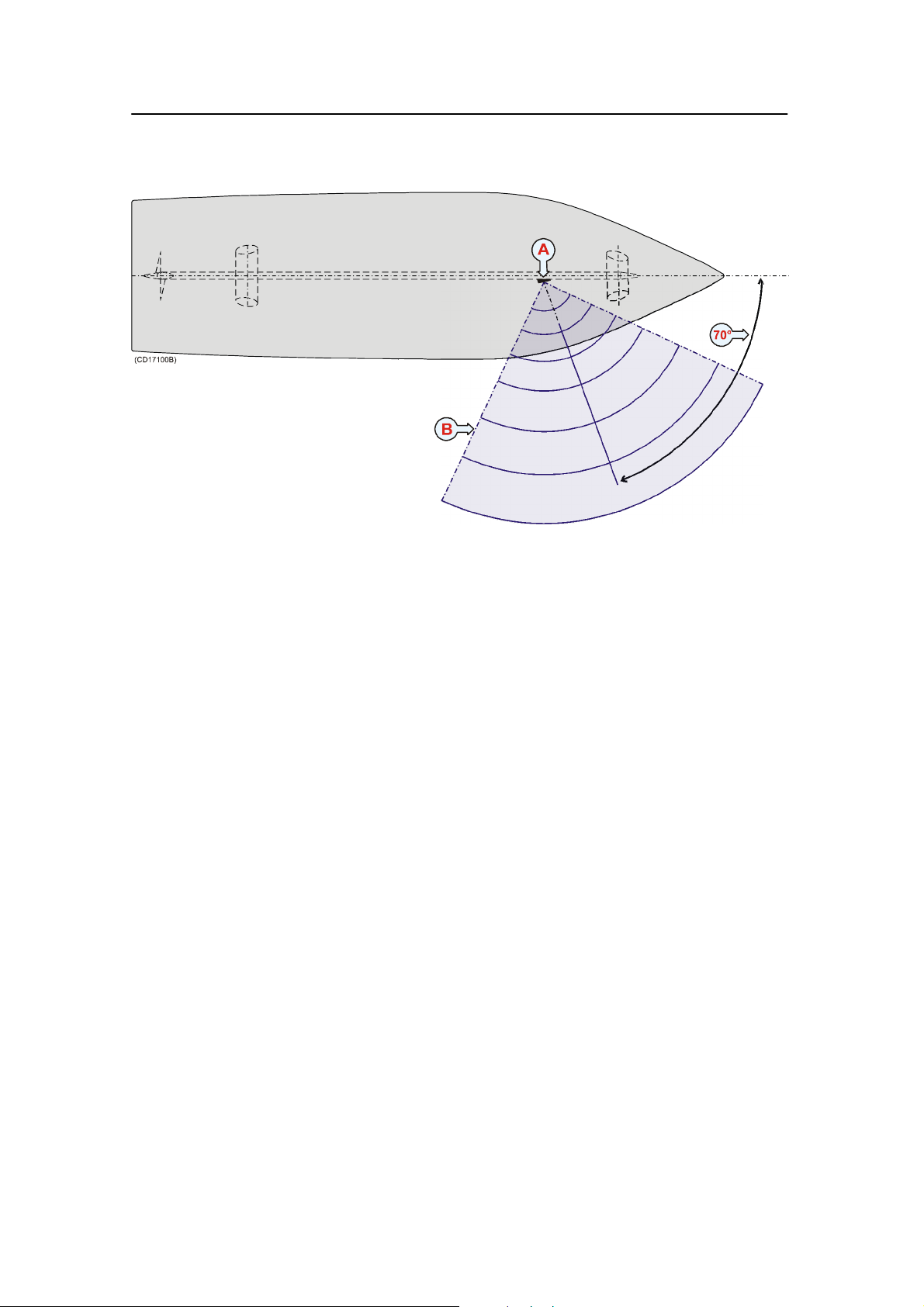
Simrad PI44
Figure 1 Horizontal
coverage area
The illustration shows a hydrophone installed at an angle of 70
degrees to the vessel’s center line.
(A) = The PI44 hydrophone
(B) = The horizontal coverage area
Vertical coverage area
The hydrophone has a vertical beam width of -30_ and should
be tilted so that the most important part of the seine is
adequately covered. Tilt should be no less than -15_ in most
instances with the optimal tilt angle depending on the size
(length/depth) of the seine in use. Heeling of the vessel after the
seine is set must also be taken into consideration. For a large
purse seine (about 1000m or longer) the recommend a tilt angle
is -15_ plus the estimated angle of heel when the net is set. For
smaller and deeper seines it may be necessary to increase the tilt
angle.
52
851-165101 / Rev.A
Page 61

Tilt angle
The tilt angle is a function of net length and depth and may be
estimated as follows:
α = - [arctan (depth/length*π)-15_+β]
α = tilt angle
β=angle of heel (to port) after deploying the purse seine to
starboard
The following table gives some examples of recommended tilt
angles for common size pure seines:
Recommended tilt angles
Purse seine hydrophone installation
Net length/depth
in meters
Recommended
tilt angle *
*The tilt angle should be increased accordingly if the vessel heels after the seine is shot. Tilt
angles of less than --15_ are not recommended.
250 / 50 350 / 100 650 / 150 850 / 180 1500 / 200 2000 / 200
-- 1 5 _ -- 2 5 _ -- 2 0 _ -- 2 0 _ -- 1 5 _ -- 1 5 _
851-165101 / Rev.A
53
Page 62

Simrad PI44
Mounting arrangement
The PI44 purse hydrophone are delivered ready for installation
in either freestanding or keel mounted shoes (which are to be
built by the shipyard responsible for the installation). Several
alternatives with corresponding detailed drawings have been
included in this manual to cover the majority of installation
options available. Information regarding through-hull
penetration is also described to compliment the rules and
regulations of the respective vessel’s classification society.
Referenced drawings
→ PI44 Purse hydrophone, outline dimensions, page 68
→ PI44 Purse hydrophone, cutout, page 69
→ Purse hydrophone, keel mounted, steel or aluminum, page 70
→ Purse hydrophone, keel mounted, sandwich or wood, page 73
→ Purse hydrophone, blister installation, page 76
54
851-165101 / Rev.A
Page 63

Purse seine hydrophone installation
Keel mounted shoes
The hydrophone shoe may be keel mounted to avoid creating an
appendage to the hull which may foul the purse wire.
Keel mounted hydrophone shoe:
(A) = Tilt angel
(B) = Vertical coverage area
(C) = Keel mounted hydrophone with
fairing
Should this solution be chosen, the
following must be taken into
consideration:
• The hydrophone must have an
unobstructed line-of-sight to the PI44
sensor(s) attached to the seine.
• The centre of the hydrophone’s beam
must be directed as much as possible
toward the bottom of the net where
the PI44 sensors are located. The tilt
angle must be increased with regard
to the expected heel of the vessel.
• For a short and deep seine a tilt angle (A) of 20_ to 25_ is
recommended. For a short and shallow or large seine a 15_
tilt angle may be best.
• If monitoring of the headline under pursing is desired the
hydrophone should not be tilted more than 15_.
• The hydrophone shoe must be mounted as deep as possible
on the keel, but not so deep that it may be damaged while
docking.
• The hydrophone shoe must be streamlined to avoid creating
turbulence and underwater noise.
• For applications that require extensive coverage, regardless
of net size, several hydrophones may be installed with
different tilt angles.
851-165101 / Rev.A
55
Page 64

Simrad PI44
Free standing hydrophone in blister
If there is no risk that hull protrusions will be fouled by the
purse wire, mounting the hydrophone in a freestanding blister is
a viable option.
Free standing hydrophone in blister:
(A) = Tilt angel
(B) = Vertical coverage area
(C) = Free standing hydrophone in
blister (pipe diameter 200 to 250 mm)
(1) = Approximately 400 mm, minimum
250 mm is required
(2) = Must exceed 700 mm.
Should this solution be chosen, the
following must be taken into
consideration:
• The centre of the hydrophone’s beam
must be directed as much as possible
toward the bottom of the net where
the PI44 sensor(s) are located. The tilt
angle should be increased with regard
to the expected heel of the vessel.
• For a short and deep seine a tilt angle (A) of 20_ to 25_ is
recommended. For a short and shallow or large seine a 15_
tilt angle may be best.
• If monitoring of the headline under pursing is desired the
hydrophone should not be tilted more than 15_.
• For applications that require extensive coverage, regardless
of net size, several hydrophones may be installed with
different tilt angles.
56
851-165101 / Rev.A
Page 65

Purse seine hydrophone installation
Dual hydrophone installation
Large vessels and operations requiring a greater than normal
coverage area can install two hydrophones with a vertical and
horizontal overlap. Hydrophone selection is made with the help
of a switch located in the wheelhouse.
To reduce the possibility of interference from air bubbles and
underwater noise when reversing propulsion or using thrusters
the two hydrophones should be located at least five meters from
each other in the fore and aft plane. It is also recommended to
install the two hydrophones with a slightly different tilt angles
so that a larger vertical sector may be covered. Vessels equipped
with a bowthruster or bulbous bow can install the first
hydrophone forward of the bowthruster on the bulbous bow and
the second aft of the bowthruster. Dual hydrophone installations
may be either keel mounted or installed in free-standing blisters.
Horizontal cove rage areas
When the seine is normally located forward of the starboard
beam when pursing the following information should be taken
into consideration:
• When the seine is pursed in the sector from approximately
000_ to about 130_ relative to the bow, the foremost
hydrophone should be installed at an angle of 50_ and the
after 90_ to the vessel’s centre line.
• Should special circumstances require coverage outside the
standard 000_ to 130_ sector the hydrophones may be
installed accordingly.
851-165101 / Rev.A
(A) = Aft hydrophone, (B) = Forward hydrophone
(C) and (D) = Horizontal coverage areas
57
Page 66

Simrad PI44
Vertical coverage areas
When the seine is normally located forward of the starboard
beam when pursing the following information should be taken
into consideration:
• The optimal tilt angle for dual
hydrophone installations is
derived in the same manner as a
for single hydrophone
installations. Consult the
section on Tilt angle for more
information.
• The hydrophones should be
tilted so that the most important
part of the seine is adequately
covered. Tilting the forward
hydrophone -25_ and the after
-15_ will provide proper
coverage in most instances.
• Tilt should be no less than -15_ in most instances with the
optimal tilt angle depending on the size (length/depth) of the
seine in use.
• Heeling of the vessel after the seine is set must be taken into
consideration when calculating the tilt angle.
58
851-165101 / Rev.A
Page 67

Purse seine hydrophone installation
Hydrophone protection
Warning: Do not perform hot work near, paint, scrape, hit,
pry, force, sandblast, high-pressure wash or
otherwise subject hydrophones to excessive
force.
Installation precautions
The following precautions must be observed. Failure to do so
can result in damage to the purse seine hydrophone which may
render the PI44 system inoperative.
1 Do not install the hydrophone until all hot work is
complete!
2 Do not over-tighten the packing nipple as this could
damage the hydrophone’s cable!
3 Observe the maximum allowable torque warning of 5 Nm
when tightening hydrophone studs!
4 Use only stainless steel M8x35 socket countersunk head
screws for mounting the hydrophone!
5 Secure threaded hydrophone hardware with Loctitet 270
or the equivalent!
6 The PI44 cabinet should always be connected to the ship’s
ground to reduce the effects of electrical interference on
the system!
Under installation
Hydrophones must not be installed until all structural work,
specifically welding sandblasting and other potentially harmful
operations are completed. If hot work, sandblasting, spay
painting or water blasting is to be performed in the vicinity of a
hydrophone it must be properly protected. PI44 hydrophones
although very rugged, contain sensitive ceramic elements and
electronic circuits and therefore should never be struck, prided,
clamped or subject to other types of potentially damaging force
as for example over-tightening mounting hardware.
851-165101 / Rev.A
Deflection plates
Simrad recommends that hydrophones mounted in blisters be
protected by rope deflections plates both forward and aft. Such
precautions will help protect the hydrophones, especially in the
event the vessel passes over a wire, line or net.
59
Page 68

Simrad PI44
Vessels operation in colder climates should weld steel fins and
protection plates installed around hydrophones to protect them
from being damaged by ice. Detailed drawing must be made
specifically to suite each individual vessel in question and the
installation performed by an authority with the expertise to do
so.
Surface protection
Maintenance and replacement costs can be reduced if those parts
of the hydrophone installation that are open to the sea are
protected correctly. Any new metal or original plating involved
in the hydrophone installation which has been cut, sand-blasted,
welded or otherwise had its protective coating compromised
must be thoroughly cleaned and repainted. For steel vessels use
polyester primer, undercoat and top-coat according to the
manufacture’s instructions, then apply the same anti-fouling
paint used on the rest of the hull.
Hydrophone face
This is Simrad’s list of approved antifouling paints for
hydrophone faces.
From Jotun Paints, Sandefjord Norway:
• Antifouling Seamate HB 33, HB 66 and HB 99
• Racing
• Non-stop
From International Paints:
• Intersleek tie coat + 425 FCS
- BXA386/BXA390/BXA391 Grey
- HKA563/HKA570/HKA571 Yellow
Mix BXA386, BXA390 and BXA391 first, then apply. When
dry, mix HKA563, HKA570 and HKA571, apply.
From Hempel IFA Coatings AS:
• Hempel A/F Classic 76550
From Jotun-Henry Clark Ltd:
• Anti-fouling Seaguardian
From International Marine Coatings:
• Intersmooth 360 Ecoloflex SPC
• Micron Ekstra
Note: Refer to the manufacturer’s documentation and data sheets for a
complete procedure.
60
851-165101 / Rev.A
Page 69

Purse seine hydrophone installation
Location and marking
After installation, the location of hydrophones should be clearly
marked on the vessel’s hull (above the water-line) directly over
them. This information will help prevent hydrophone damage
when dry-docking the vessel. It is very important to amend the
docking-plans of larger vessels to also reflect this information so
that blocks will not be placed in the vicinity of hydrophones,
fins, deflection plates or other associated appendages.
After installation / Sea trials
Once the installation is complete and the vessel afloat, the
system’s performance should be documented. Refer to the
appropriate section in the PI44 Operation manual regarding the
measurement of a noise vs. speed curve.
851-165101 / Rev.A
61
Page 70

Simrad PI44
Hydrophone cable
The purse seine hydrophone is delivered with a 22 m cable. The
cable is fitted with plug that fits the ANT socket on the rear side
of the PI44 Operator Unit.
General cable gland guidelines
Hydrophone cables are passed through the hull using approved
cable glands for the type of vessel in question. The standard
delivery consists of a steel cable gland that is to be welded to
the hull.
A bronze cable gland can be delivered as an option for vessels
with wood or fibreglass construction. Vessel not to be classified
can as an option use a cable gland made of plastic.
Note: Simrad strongly recommends that a length of conduit be fitted
around hydrophone cable glands made of steel or bronze and
extended over the water-line inside the vessel. This precaution
reduces the danger of flooding in the event of gland failure and
hydrophones installed in this manner are also easier to replace.
Some vessels may experience difficulties finding suitable areas
of the hull for mounting hydrophone cable glands due to
existing water tanks, concrete ballast or other obstacles. A
possible solution in such cases is to run the hydrophone cables
in a steel conduit aft along the hull until a suitable cable gland
location is available. The respective cable gland can then be
installed as described in the following instructions.
Note: Simrad takes no responsibility for the correct installation of
cable glands, associated hull modifications and/or structural
support of hydrophone cable penetration. These activities are
subject to individual approval by the respective classification
society for the vessel in question.
Order numbers
Steel hull cable gland kit: 599-202216
Wood/GRP hull cable gland kit: 119-038200
Small vessel cable gland kit: 599-202182
62
851-165101 / Rev.A
Page 71

Purse seine hydrophone installation
Cable gland installation for steel hulls
The cable gland kit for steel vessels is included with standard
deliveries. The drawing shows a single hydrophone, but
normally a typical installation includes two hydrophones with
respective cables spliced in a junction box and run to the
wheelhouse in a conduit.
Cable gland for steel hull
vessels.
(A) = Steel conduit
(B) = Stuffing tube, DNV
approved carbon steel st52.3
(C) = Washers, 24 x 8 x 2 mm
(D) = Rubber gasket
(E) = Packing nipple. Make
sure that you do not damage the
hydrophone cable by tightening
the packing nipple too hard!
(F) = Cable to the PI Operator
unit (or a junction box)
The gland gland kit includes all
of the necessary parts needed to
install the unit excluding
screws.
851-165101 / Rev.A
63
Page 72

Simrad PI44
Gland installation for wood or GRP hulled vessels
A bronze cable gland kit is available for wood and GRP vessels.
This kit is not included in the standard delivery, and must be
ordered separately .
The drawing shows a single hydrophone, but normally a typical
installation includes two hydrophones with respective cables
spliced in a junction box and run to the wheelhouse in a conduit.
Cable gland for wood and GRP
hulls.
(A) = Packing nipple. Make
sure that you do not damage the
hydrophone cable by tightening
the packing nipple too hard!
(B) = Washers
(C) = Rubber gaskets
(D) = Hole diameter 28 mm
(E) = Steel conduit
(F) = Hydrophone cable
The gland gland kit includes all
of the necessary parts needed to
install the unit excluding
screws.
Simrad recommends that a one inch conduit (that the
hydrophone cable will be run through) with an inside threaded
diameter of three-quarter inches be attached to the gland’s
packing nipple. This connection must be watertight, and the
conduit must extend to over the vessel’s water line and
terminated as described for steel hulled vessels.
64
851-165101 / Rev.A
Page 73

Purse seine hydrophone installation
Cable gland installation for smaller vessels
Cable glands made of plastic for those smaller vessels that do
njot need to be classified are optional equipment for standard
deliveries. This cable gland kit is not included in the standard
delivery, and must be ordered separately.
The drawing shows a single hydrophone, but normally a typical
installation includes two hydrophones with respective cables
spliced in a junction box and run to the wheelhouse in a conduit.
Hydrophone cable gland for
small vessels.
(A) = Packing nut (bronze).
Ensure that you do not to
damage the hydrophone cable
by tightening the packing nut
too hard!
(B) = Rubber gasket
(C) = Plastic disk
(D) = Rubber gasket
(E) = Stuffing tube
(F) = Backing nut (bronze)
(G) = Backing washer (plastic)
(H) = O-ring 42.5 x 3.0 N
(I) = O-ring 39.5 x 3.0 N
(J) = Hydrophone cable
Stuffing tube hole diameter: 36 mm ±1.5 mm.
Apply ample amount of sealant between the backing washer (H)
and the hull plate.
The cable gland kit contains all the listed parts, except the
sealant.
Note: The two O-rings must be clean, in good condition and free of cuts
or other defects which could affect their water-tight integrity.
851-165101 / Rev.A
65
Page 74

Simrad PI44
Splicing
If you need to cut the cable, you must splice it correctly.
Note: DO NOT solder the wires together with only electrical tape for
insulation, as this will result in electrical noise and reduced
operational performance.
To splice the cable, use a metal junction box. The chassis of the
junction box must be grounded, but the cable shielding must
NOT be connected to the junction box ground.
Note: Make sure that you connect the cables 1:1! The red cable in the
“input” cable MUST be connected to the red cable in the
“output” cable etc.
Cable specification
If extension cables are used, these must be supplied by the
installation shipyard. The following specifications must be
regarded as a minimum:
2x2x0.5mm
2
/ Twisted pairs / Overall braided
Observe the information regarding cable splicing.
Grounding and shielding
Cable shielding must be continuous. The shielding is terminated
in the cabinet and must not be grounded in the junction boxes.
In order to minimize electrical interference, Simrad strongly
recommends that the hydrophone cable is installed in a metal
conduit between the hydrophone and the PI44 cabinet.
66
851-165101 / Rev.A
Page 75

Purse seine hydrophone installation
Installation drawings
Observe the following drawings. The drawings are also
available on electronic format (DWG or PDF), consult your
local dealer.
→ PI44 Purse hydrophone, outline dimensions, page 68
→ PI44 Purse hydrophone, cutout, page 69
→ Purse hydrophone, keel mounted, steel or aluminum, page 70
→ Purse hydrophone, keel mounted, sandwich or wood, page 73
→ Purse hydrophone, blister installation, page 76
851-165101 / Rev.A
67
Page 76

Simrad PI44
68
PI44 Purse Seine hydrophone - Outline dimensions
851-165101 / Rev.A
Page 77
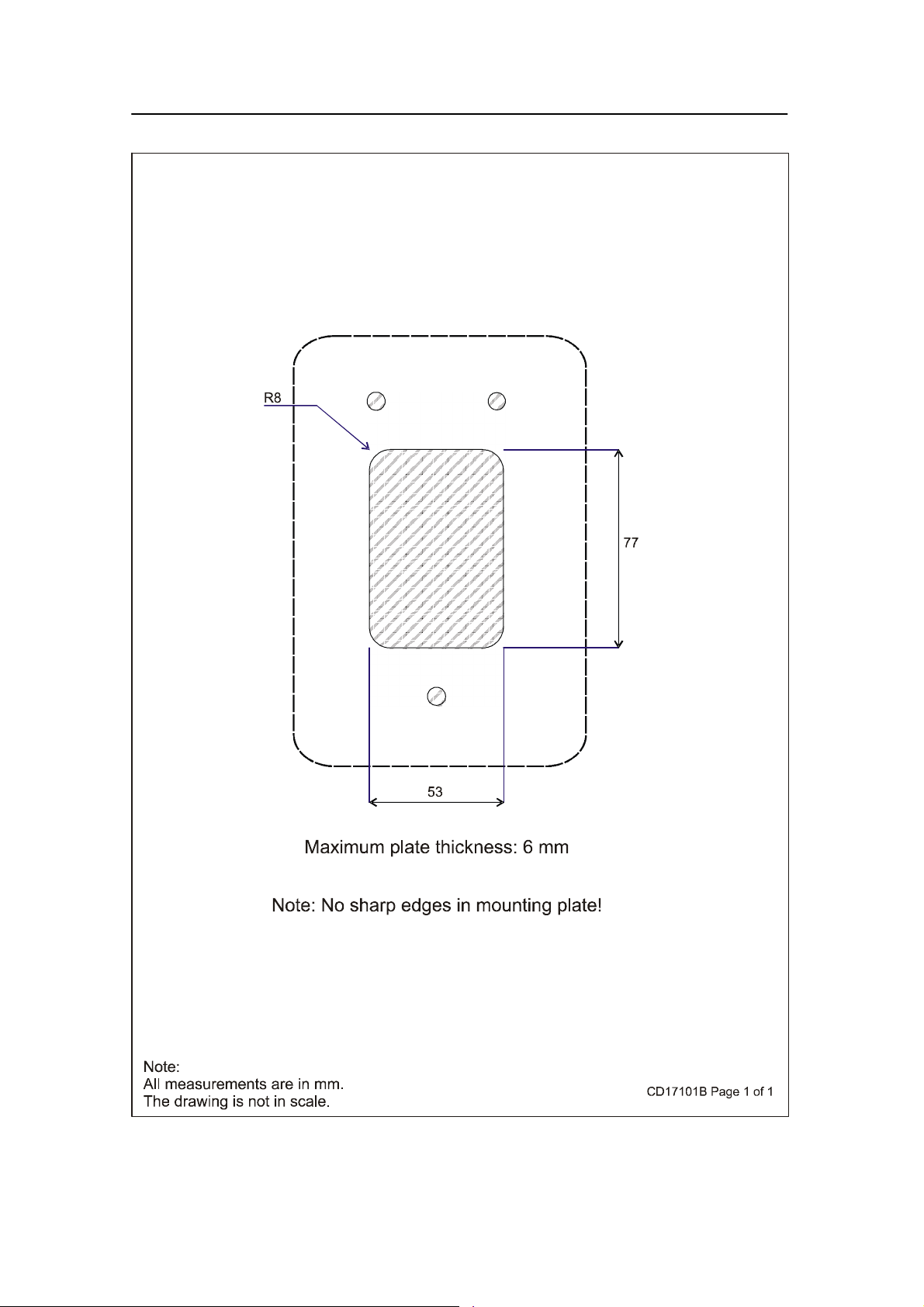
Purse seine hydrophone installation
851-165101 / Rev.A
PI44 Purse Seine hydrophone - Cutout
69
Page 78

Simrad PI44
PI44 Purse Seine hydrophone - Keel mounted hydrophone, steel hull - Page 1
70
851-165101 / Rev.A
Page 79
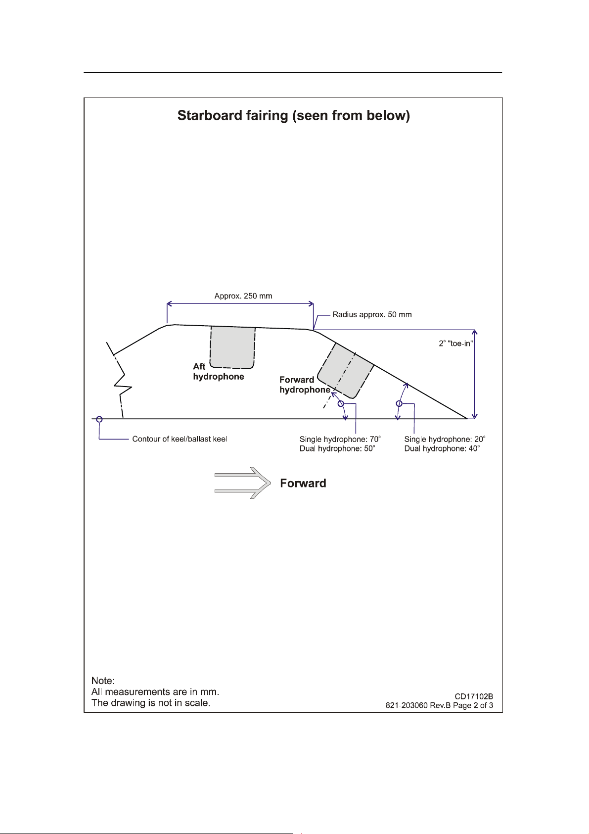
Purse seine hydrophone installation
PI44 Purse Seine hydrophone - Keel mounted hydrophone, steel hull - Page 2
851-165101 / Rev.A
71
Page 80
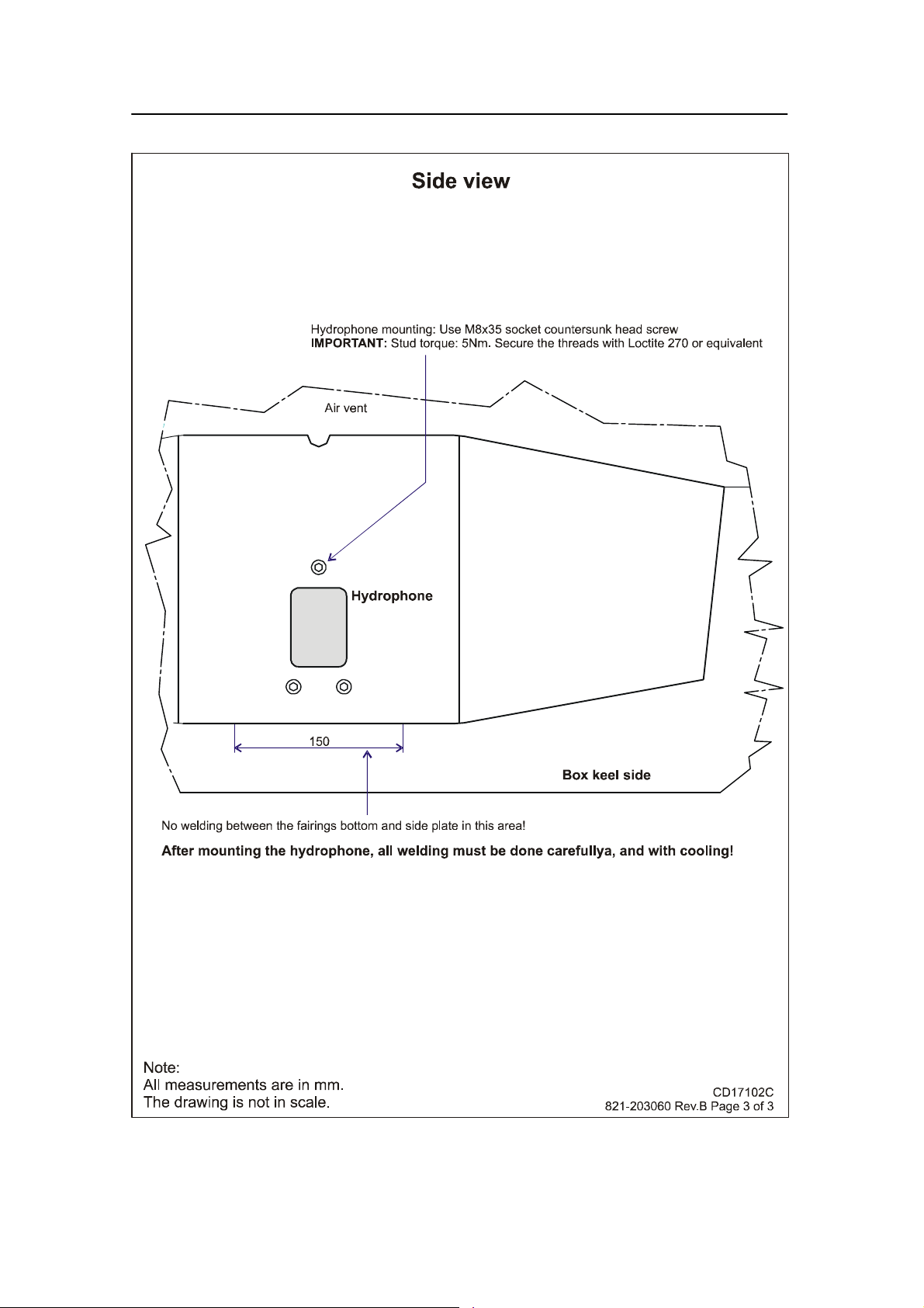
Simrad PI44
PI44 Purse Seine hydrophone - Keel mounted hydrophone, steel hull - Page 3
72
851-165101 / Rev.A
Page 81

Purse seine hydrophone installation
PI44 Purse Seine hydrophone - Keel mounted hydrophone, wooden hull - Page 1
851-165101 / Rev.A
73
Page 82
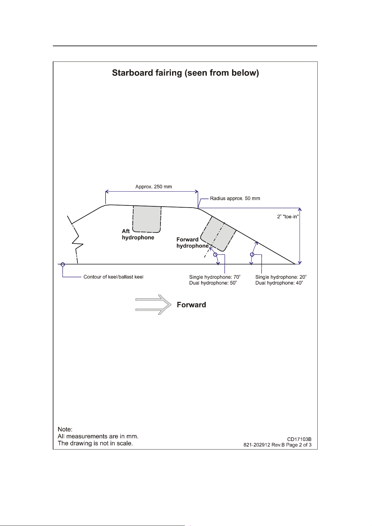
Simrad PI44
PI44 Purse Seine hydrophone - Keel mounted hydrophone, wooden hull - Page 2
74
851-165101 / Rev.A
Page 83
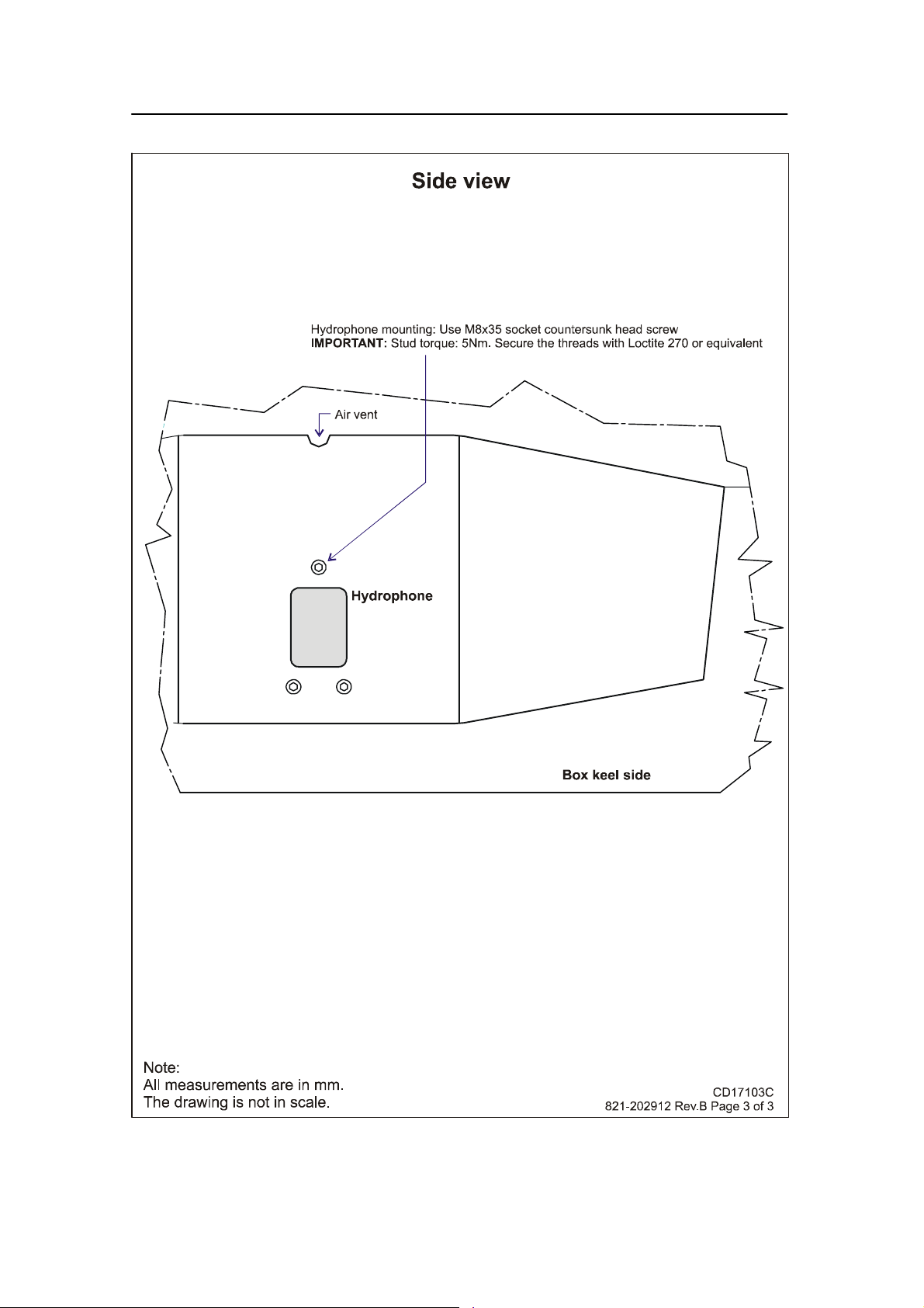
Purse seine hydrophone installation
PI44 Purse Seine hydrophone - Keel mounted hydrophone, wooden hull - Page 3
851-165101 / Rev.A
75
Page 84

Simrad PI44
76
PI44 Purse Seine hydrophone - blister installation on steel hull - Page 1
851-165101 / Rev.A
Page 85

Purse seine hydrophone installation
PI44 Purse Seine hydrophone - blister installation on steel hull - Page 2
851-165101 / Rev.A
77
Page 86

Simrad PI44
78
PI44 Purse Seine hydrophone - blister installation on steel hull - Page 3
851-165101 / Rev.A
Page 87

Trawl hydrophone installation
4 TRAWL HYDROPHONE
Purpose
The purpose of this chapter is to provide general guidelines for
the installation of the PI44 hydrophone for trawl..
Note: If your vessel shall be fitted for purse seine operations, DO NOT
install the hydrophone(s) as explained in this chapter!
Order numbers
Trawl hydrophone, complete: HYD-205254
Trawl hydrophone, without cable gland: HYD-205826
Topics
→ Precautions, page 80
→ Considerations, page 81
→ Pre-installation checklist, page 86
→ Location, page 88
→ Coverage area, orientation and tilt, page 91
→ Mounting arrangement, page 95
→ Dual hydrophones, page 101
→ Hydrophone protection, page 102
→ Hydrophone cable, page 105
→ Installation drawings, page 110
851-165101 / Rev.A
79
Page 88

Simrad PI44
Installation precautions
Caution: The following precautions must be observed. Failure to
do so can result in damage to the hydrophone which
may render the PI44 catch monitoring system
inoperative.
1 Observe the maximum allowable torque warning of 5 Nm
when tightening the hydrophone studs.
2 Use only M8x30 socket countersunk head screws for
mounting the hydrophone.
3 Secure threaded hydrophone hardware with Loctitet 270
or the equivalent.
4 Do not paint the hydrophone.
5 Do not sand-blast, power or steam wash the hydrophone.
6 Do not scrape the hydrophone with metal or other hard
objects that may damage the polyurethane sheathing.
7 Do not strike the hydrophone.
8 Do not expose the hydrophone to harsh chemicals.
9 Do not perform hot work in the vicinity of the
hydrophone.
10 Do not lift the hydrophone by its cable.
80
851-165101 / Rev.A
Page 89

Trawl hydrophone installation
Considerations
Correct installation of PI44 hydrophone(s) is vital to system
performance. Several variables must be taken into consideration,
the most important of which is the vessel’s construction. This
guide is for use in selecting the best location for the hydrophone
and includes a brief description of areas to be avoided.
Note: Simrad strongly suggests that this information is read
thoroughly, and that the instructions are understood and
followed. Proper hydrophone placement is difficult to achieve,
but essential for correct system operation.
Depth
Water just below the sea surface contains a myriad of small air
bubbles created by the turbulence of breaking waves. The first
five to ten metres may be heavily saturated in moderate seas
with the greatest concentration and largest bubbles closest the
surface. Air bubbles disrupt sound waves in water. The degree
to which they absorb and reflect such energy vary, but in some
cases they can block hydrophone reception. It is therefore
recommended to mount the unit as deep as possible.
Pounding danger
When a vessel is in ballast and pitching in heavy seas, it is
important that the hydrophone is not lifted out of the water.
Should a vessel pound so heavily that the hydrophone be
exposed, sound reception will be interrupted and the unit may
be damaged on impact.
The boundary layer
The flow of water in the immediate vicinity of the hull of a
moving vessel is known as a boundary layer. This flow is
responsible for underwater noise that can disturb hydrophone
reception and its thickness is contingent on a vessel’s:
• Hull form
• Size and number of underwater protrusions
• Velocity
• Hull roughness
The boundary layer is thin (laminar flow) near the vessel’s bow
and becomes thicker (turbulent flow) as it moves aft. Laminar
flow is smooth with streamlines approximately parallel to the
hull and contributes relatively little to noise created by flow.
Conversely, turbulent flow is more disorderly and in turn
contributes to a greater extent.
851-165101 / Rev.A
81
Page 90

Simrad PI44
Boundary water layers:
(A) = Turbulent flow
(B) = Laminar flow
(C) = Air bubbles in the water
Air bubbles may also be introduced into the boundary layer. If
the vessel’s hull has little flare and is relatively narrow, bubbles
may escape to the sea surface without incident. On the other
hand a wide, flat hull with minimal deadrise is prone to trapping
air bubbles no matter how little flare it has. Regardless of a
vessel’s hull form, hydrophones are generally recommended to
be installed on the forward part of the hull to minimising the
influence of both turbulence and air bubbles.
Bulbous bow
The bulbous bow may be an acceptable hydrophone location.
Should this position be chosen, the foremost part of the bulb is
often best, but also the m ost susceptible to pounding.
Figure 2 Transducer
location on a bulbous
bow
82
851-165101 / Rev.A
Page 91

Trawl hydrophone installation
Propeller noise
A vessel’s main propeller is the dominant source of underwater
acoustic noise. When ever possible, hydrophone(s) should be
located as far a way as possible from the main propeller and
never closer than ten meters. Hydrophone(s) should not be
mounted in the direct acoustic path (line-of-sight) of the main
propeller unless absolutely necessary.
The primary cause of propeller noise is cavitation (small
bubbles generated by the partial vacuum created by the blades as
they pass through the water). The resulting underwater acoustic
noise from cavitation is normally weakest on the side of the
vessel were the propeller blades rotate toward the surface and
most pronounced on the side were they rotate toward the
bottom. Most vessels have clock-wise rotating propellers
resulting in their port sides being less effected by cavitation
induced noise than their starboard.
To minimise the negative effect of cavitation noise on
hydrophone performance, installation is generally recommended
as follows:
• Single hydrophone - if only one hydrophone is to be
installed on a vessel with a clock-wise rotating propeller, it
should be located on the port side of the hull.
• Dual hydrophones - if two hydrophones are to be installed,
they should be placed on either side of the vessel’s keel.
When in doubt about the best fore-and-aft location for
hydrophones, they can be placed at different distances from
the bow (for example the port hydrophone can be a little
further aft than the starboard, approximately three to five
meters for a thirty-five meter vessel). When trawling in both
deep and shallow water the hydrophones should also be tilted
differently with respect to each other. The hydrophone that is
closest to the propeller should have the greatest tilt and be
located on the port side of the hull for a vessels with
clock-wise rotating propellers.
Bow/sternthruster noise
851-165101 / Rev.A
Bow and sternthruster operation may severely effect
hydrophone reception. Hydrophone installation closer than four
meters to either is strongly discouraged.
83
Page 92

Simrad PI44
When not in operation, bow/sternthruster tunnels create
turbulence and hence underwater noise when a vessel is under
way. Also, as a vessel pitches in heavy weather, thruster tunnels
may fill with air or aerated water which can disturb hydrophone
reception when released. Hydrophone installation should take
into regard the noise and down stream disturbances found
around and aft of thrusters.
Note: Hydrophone installation must take into regard the noise and
down stream disturbances found around and aft of thrusters.
Noise from protruding objects and other sources
The primary sources of underwater disturbance (other than a
vessel’s main propeller and bow/sternthruster) that affect
hydrophone reception are:
• Main or bilge keels
• Zinc anodes
• Cooling elements protruding from the hull
• Equipment such as sonar hydrophones and pitot tubes
• Sea chests
• Overboard discharges
• Dents in the hull
All appendages to the hull, indentations and pipe outlets are
potential sources of underwater noise. They may act as resonant
cavities amplifying noise at certain frequencies, create cavitation
or turbulence. Hydrophones should not be located in the vicinity
of such objects and especially not immediately aft of them.
Minimum distance to sonar and echo sounder
transducers
To avoid interference, PI44 hydrophone(s) must be installed as
far away as possible from other sources of underwater acoustical
energy such as active sonars and echo sounder transducers.
Hydrophones should be placed at least two meters from such
equipment when ever possible and distances of less than one
meter avoided. Hydrophones installed in close proximity to
underwater acoustical sources should be located as far aft as
possible from them, and most importantly, not be subjected to
direct (frontal) transmission from such equipment.
84
851-165101 / Rev.A
Page 93

Trawl hydrophone installation
Drop keel
In the event the vessel is equipped with a drop keel, the
hydrophones should be mounted aft of it. The choice between
installing a one, or two hydrophone system should be based on
the same horizontal and vertical coverage requirements for
vessels operating under similar conditions with fixed keels.
851-165101 / Rev.A
85
Page 94

Simrad PI44
Pre-installation check-list
Choosing the optimal locations for hydrophones is not always
easy, but decisions made at this phase of the installation process
are critical to future system performance. Determining the best
configuration for a given vessel often involves a compromise
between contradicting requirements.
To aid in this evaluation process Simrad recommends that this
installation manual be read thoroughly and the following check
list completed before deciding on a final installation strategy for
the PI44 system.
1 Hydrophones do not have a direct line-of-sight to the main
propeller and are placed where the vessel’s hull protects
them from underwater acoustic noise as well as possible.
2 Hydrophones must always have an unobstructed
line-of-sight to the sensors attached to the gear for the
system to operate properly.
3 The distance from the main propeller to the hydrophones
should be greater than ten meters. A separation of less
than ten meters can reduce system range significantly.
4 If thrusters are installed, hydrophones should be located at
least four meters from them.
5 Avoid locating hydrophones behind thrusters where air
bubbles from their tunnels generated when the vessel
pounds can block sensor signals.
6 Hydrophone should not be placed forward of other
underwater acoustic equipment and preferably behind it as
far away as possible, distances of less than one meter
should be avoided.
7 There should never be possible sources of underwater
acoustic noise placed in front of hydrophones.
8 Hydrophones should be offset twenty degrees from the
vessel’s centre line for normal single boat trawling. This
provides a ten degree overlap and a coverage area of
ninety degrees aft. Refer to the corresponding sections of
this manual for more information.
86
9 If there is any doubt about the best fore-and-aft location,
the port hydrophone can be placed a little farther aft (three
to five meters) in relation to the starboard. Hydrophones
can be tilted at slightly different angles when operating in
both deep and shallow waters. Refer to the corresponding
sections of this manual for more information.
851-165101 / Rev.A
Page 95

Trawl hydrophone installation
10 The hydrophone that is closest to the main propeller
should be located on the port side of the vessel and have
the greatest tilt.
11 If both hydrophone are located equally distant from the
main propeller, but are tilted differently, the starboard
hydrophone should be tilted the most because underwater
acoustic noise is more prevalent on that side of the vessel.
12 Locating hydrophones at the after end of a bulbous bow
can produce good results. Previously installed sonars in
this area that can subject hydrophones to direct signals
will produce interference.
13 Hydrophone can also be mounted in the after end of echo
sounder shoes as long as the minimum required distances
and orientation with regard to other underwater acoustic
equipment is observed.
14 Remember that hydrophones are to be mounted with their
long axis up (in the vertical plane).
15 Hydrophones installed in blisters should be located away
from the vessel’s keel and as deep as possible on the hull.
16 Hydrophones installed in shoes along the vessel’s keel
should be mounted as deeply as possible.
17 Hydrophone cables that are run in conduit along the
outside of the vessels hull should be arranged as to
produce the least amount of underwater acoustic noise as
possible.
18 Blisters and shoes should be as streamlined as possible and
have all of their corners rounded to minimize the
generation of underwater acoustic noise.
19 Conduit used to run hydrophone cables in the interior of a
vessel’s hull should extend well over its water line.
20 If you install both trawl and purse seine hydrophones, do
not confuse the two types. The Trawl hydrophones are
marked with order number 314-205250, while the Purse
seine hydrophones are marked with order number
314-202275.
21 Other well-founded information or experience regarding
hydrophone installation be available should also be
evaluated even though not directly mentioned in these
instructions.
851-165101 / Rev.A
87
Page 96

Simrad PI44
Optimal location of trawl hydrophones
The most influential factors effecting hydrophone reception
common to most vessels are:
• Noise from cavitation generated by the main propeller.
• Air bubbles in the water around the hydrophone which
impede acoustic signals.
• Noise from other acoustic equipment mounted in close
proximity.
If the shipyard or persons responsible for placement and
mounting the hydrophone(s) have knowledge and the proper
experience with installation of similar equipment, it should be
fully exploited when deciding where to locate the hydrophones.
This also holds true for adjusting the degree to which a
hydrophone should be tilted with regard to the both the vessel’s
physical characteristics and fishing method. Proper hydrophone
installation can increase overall system performance more than
any other single factor and therefore it is important that all the
variables involved be understood and taken into account. Often,
individual hydrophone installation requirements contradict one
an other and only an in-depth knowledge of the principles
involved can aid in deciding which should be given priority.
General rules-of-thumb
Although individual vessel vary greatly with regard to physical
construction and fishing methods, the following rules of thumb
apply under most circumstances.
• Hydrophones should be located as far forward as possible,
normally one-third the length of the water-line from the bow.
• If a vessel has a bow thruster, bubbles generated by its tunnel
can block sensor signals. Hydrophones therefore should be
either located forward of bow thrusters or far aft out of the
stream of bubbles found behind them. Vessels equipped with
bulbous bows can mount hydrophones in a specially designed
shoe on the after part of the bulb, forward of the bow
thruster.
• The minimum distance a hydrophone should be located from
the main propeller is ten meters. Systems with hydrophones
mounted closer than this will have reduced range due to
underwater acoustic noise generated by propeller cavitation.
• For trawlers that do not have to take a pursing wire into
consideration, hydrophones can be mounted in specially
constructed blisters offset from the vessel’s keel (preferably
1200 mm, but no less than 700 mm) to avoid turbulence. To
88
851-165101 / Rev.A
Page 97

Trawl hydrophone installation
also aid in reducing the effects of turbulence, hydrophones
should be installed as deeply as possible (preferably 600 mm,
but not less than 400 mm) from the vessel’s outer hull. When
ever possible, the distance from the keel to the bottom of the
hydrophone blister should not exceed 50 mm which can be
adjusted by countersinking the installation.
• Keel installation of hydrophones is recommended for
combined trawl/purse seining vessels that can not have
blisters projecting from their hulls.
On the starboard side of such vessels a purse seine
hydrophone can be installed together with a trawl
hydrophone.
• Hydrophones should have and unobstructed “view” of the
sensors attached to the gear, but not be located in the
line-of-sight of the main propeller.
• Hydrophones should be located aft of echo sounder
transducers or sonar installations, preferable at a distance of
two meters or more. A proximity of less than one meter
should be avoided and hydrophones should never be subject
to their direct (frontal) transmission.
• Objects protruding from the hull will generate noise, the
areas aft of which should not be used to mount hydrophones.
• Thruster tunnels generate air bubbles which disrupt signals
from the sensors. The areas aft of thruster tunnels or other
sunken areas of the hull should not be used to mount
hydrophones.
• If there is any doubt about the fore-and-aft positions for the
hydrophones, they should be located at different distances
from the bow (three to five meters relative to each other for a
thirty-five meter vessel). The hydrophone that is closest the
main propeller should be located on the port side of the
vessel.
• Hydrophones have a horizontal coverage of approximately
50 degrees. To maximise coverage using two hydrophones
they should be offset preferably 20 degrees outboard. With
this configuration the two hydrophones will overlap each
other by preferably 10 degrees and provide a total system
coverage of 90 degrees.
• Hydrophones have a vertical coverage of approximately 30
degrees. The normal tilt angle is 20 degrees; if the system is
to be used in deep water the hydrophones should be tilted
preferably 30 degrees and in shallow water preferably 10
degrees. To maximise coverage using two hydrophones when
851-165101 / Rev.A
89
Page 98

Simrad PI44
trawling in both deep and shallow water tilt one preferably
15 degrees and the other preferably 30 degrees. The
hydrophone closes to the propeller should be tilted the most
and care should be taken with regard to underwater acoustical
noise.
• Hydrophone cables pass through a vessel’s hull below its
water-line. It is therefore strongly recommended that a length
of conduit be fitted (using approve fastening procedures) to
the interior of hull around the opening made for the
hydrophone’s cable. This conduit should extend vertically
(inside the vessel) over the water-line so that hydrophone
cables can be safely passed through the hull without the
danger of flooding in the event of gland failure. Hydrophones
with steel through-hull fittings installed in this manner can be
replaced without the necessity of dry docking.
• The cable between the hydrophone and the cabinet must be
properly shielded from other potential sources of electrical
interference. A good practice is to run the hydrophone cable
in a steel conduit to the wheel house.
90
Figure 3 Recommended hydrophone locations
The illustration shows the recommended (A) and the alternative
(B) locations for single hydrophone locations. For a dual
installation, use position (A), and place the port hydrophone
further aft than the starboard. (L) is the total length of the hull
measured at the waterline.
851-165101 / Rev.A
Page 99
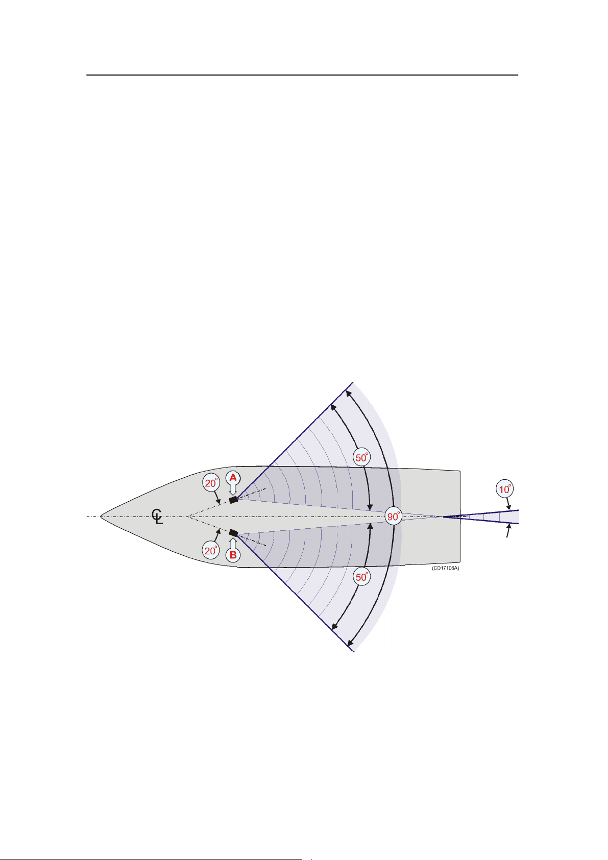
Trawl hydrophone installation
Coverage area, orientation and tilt
Once the fore-and-aft placement of the hydrophone is decided, it
is equally important to carefully consider its horizontal and
vertical orientation. Hydrophone orientation can have a large
influence on system performance.
Hydrophones must be configured so that they overlap one an
other in the horizontal plane. Tilt is decided by the actual depth
of the gear. If fishing operations are to be conducted in both
deep and shallow water the hydrophones can be tilted
differently.
Horizontal cove rage area
The hydrophone’s beam sensitivity is concentrated within a 50
degrees horizontal and -30 degrees vertical sector. By off-setting
hyprophones by 20 degrees each from the vessel’s centre line an
overlapping coverage area of 20 degrees is provided with a total
coverage area of 90 degrees.
851-165101 / Rev.A
Horizontal coverage area
(A) = Starboard hydrophone
(B) = Port hydrophone
This “rule-of-thumb” is for normal trawling operations. For
pair-trawling or when fishing with Danish seines, the horizontal
position of the hydrophones should be configured with regard to
the operation in question.
91
Page 100

Simrad PI44
Vertical coverage area I
Dual hydrophone installation with hydrophones equally distant
from the bow, but tilted differently.
Typical tilt configuration for operation in both deep and shallow
water when the hydrophones have the same distance from bow.
The hydrophones may be installed in shoes or blisters.
(A) = Using shoes (top view)
(B) = Using blisters (top view)
(C) = Port hydrophone tilted 10 to 20 degrees
(D) = Starboard hydrophone tilted 20 to 35 degrees
(K) = Keel
The hydrophone on the starboard side of the hull should have
the greater tilt of the two, approximately 20 to 35 degrees. The
hydrophone on the port side of the hull should be tilted
approximately 10 to 20 degrees
92
851-165101 / Rev.A
 Loading...