

Page 1

ENGLISH
NSS evo3
Installation Manual
Page 2

Preface
Disclaimer
As Navico is continuously improving this product, we retain the right to make changes to the
product at any time which may not be reflected in this version of the manual. Please contact
your nearest distributor if you require any further assistance.
It is the owner’s sole responsibility to install and use the equipment in a manner that will not
cause accidents, personal injury or property damage. The user of this product is solely
responsible for observing safe boating practices.
NAVICO HOLDING AS AND ITS SUBSIDIARIES, BRANCHES AND AFFILIATES DISCLAIM ALL
LIABILITY FOR ANY USE OF THIS PRODUCT IN A WAY THAT MAY CAUSE ACCIDENTS, DAMAGE
OR THAT MAY VIOLATE THE LAW.
Governing Language: This statement, any instruction manuals, user guides and other
information relating to the product (Documentation) may be translated to, or has been
translated from, another language (Translation). In the event of any conflict between any
Translation of the Documentation, the English language version of the Documentation will
be the official version of the Documentation.
This manual represents the product as at the time of printing. Navico Holding AS and its
subsidiaries, branches and affiliates reserve the right to make changes to specifications
without notice.
Copyright
Copyright © 2016 Navico Holding AS.
Warranty
The warranty card is supplied as a separate document.
Compliance statements
This equipment complies with:
• CE under 2014/53/EU Directive
• The requirements of level 2 devices of the Radio communications (Electromagnetic
Compatibility) standard 2008
• Part 15 of the FCC Rules. Operation is subject to the following two conditions: (1) this
device may not cause harmful interference, and (2) this device must accept any
interference received, including interference that may cause undesired operation.
Industry Canada
IC RSS-GEN, Sec 7.1.3 Warning Statement- (Required for license exempt devices)
This device complies with Industry Canada license-exempt RSS standard(s). Operation is
subject to the following two conditions: (1) this device may not cause interference, and (2)
this device must accept any interference, including interference that may cause undesired
operation of the device.
Le présent appareil est conforme aux CNR d’Industrie
Canada applicables aux appareils radio exempts de licence. L’exploitation est autorisée aux
deux conditions suivantes: (1) l’appareil ne doit pas produire de brouillage, et (2) l’utilisateur
de l’appareil doit accepter tout brouillage radioélectrique subi, même si le brouillage est
susceptible d’en compromettre le fonctionnement.
Warning
The user is cautioned that any changes or modifications not expressly approved by the party
responsible for compliance could void the user’s authority to operate the equipment.
Preface | NSS evo3 Installation Manual
3
Page 3

This equipment generates, uses and can radiate radio frequency energy and, if not installed
and used in accordance with the instructions, may cause harmful interference to radio
communications. However, there is no guarantee that the interference will not occur in a
particular installation. If this equipment does cause harmful interference to radio or television
reception, which can be determined by turning the equipment off and on, the user is
encouraged to try to correct the interference by one or more of the following measures:
• Reorient or relocate the receiving antenna
• Increase the separation between the equipment and receiver
• Connect the equipment into an outlet on a circuit different from that of the receiver
• Consult the dealer or an experienced technician for help
Internet usage
Some features in this product use an internet connection to perform data downloads and
uploads. Internet usage via a connected mobile/cell phone internet connection or a pay-perMB type internet connection may require large data usage. Your service provider may charge
you based on the amount of data you transfer. If you are unsure, contact your service
provider to confirm rates and restrictions.
Countries of intended use in the EU
AT - Austria
BE - Belgium
BG - Bulgaria
CY - Cyprus
CZ - Czech Republic
DK - Denmark
EE - Estonia
FI - Finland
FR - France
DE - Germany
GR - Greece
HU - Hungary
IS - Iceland
IE - Ireland
IT - Italy
LV - Latvia
LI - Liechtenstein
LT - Lithuania
LU - Luxembourg
MT - Malta
NL - Netherlands
NO - Norway
PL - Poland
PT - Portugal
RO - Romania
SK - Slovak Republic
SI - Slovenia
ES - Spain
SE - Sweden
CH - Switzerland
TR - Turkey
UK - United Kingdom
4
Preface | NSS evo3 Installation Manual
Page 4
Trademarks
Navico® is a registered trademark of Navico.
Simrad® is used by license from Kongsberg.
NMEA® and NMEA 2000® are registered trademarks of the National Marine Electronics
Association.
FLIR® is a registered trademark of FLIR.
Mercury® is a registered trademark of Mercury.
SmartCraft VesselView® is a registered trademark of Mercury.
Suzuki® is a registered trademark of Suzuki.
SimNet® is a registered trademark of Navico.
C-MAP® is a registered trademark of C-MAP.
SD™ and microSD™ are trademarks or registered trademarks of SD-3C, LLC in the United
States, other countries or both.
HDMI® and HDMI™, the HDMI Logo, and High-Definition Multimedia Interface are trademarks
or registered trademarks of HDMI Licensing LLC in the United States and other countries.
Navico product references
This manual refers to the following Navico products:
• Broadband Sounder™ (Broadband Sounder)
• DownScan Overlay™ (Overlay)
• GoFree™ (GoFree)
• Halo™ Pulse Compression Radar (Halo Radar)
• INSIGHT GENESIS® (Insight Genesis)
• StructureScan® (StructureScan)
About this manual
This manual is a reference guide for installing NSS evo3 units.
Important text that requires special attention from the reader is emphasized as follows:
Ú
Note: Used to draw the reader’s attention to a comment or some important information.
Warning: Used when it is necessary to warn personnel that they should
proceed carefully to prevent risk of injury and/or damage to equipment/
personnel.
Preface | NSS evo3 Installation Manual
5
Page 5

Contents
8 Check the contents
9 Overview
9
Front controls
10 Rear connections
10 Card reader
11 Installation
11 Mounting location
12 Bracket mounting
12 Flush mounting
13 Bezel Fitment and Removal
13 Transducer mounting location
15 Wiring
15 Guidelines
15 Power connection
15 Power Control connection
17 Power Control master/slave bus
18 External alarm
18 Connect an external monitor
19 NMEA 2000 backbone
20 NMEA 0183 device connection
21 CZone connection to NMEA 2000
21 Transducer connection
22 Ethernet connector
23 Video in
24 Software Setup
24 First time startup
24 Configuring the WheelKey
24 Time and Date
24 Power Control
24 Data source selection
26 Device list
26 SimNet Groups
26 Diagnostics
27 Damping
27 Calibration
27 External Alarm Setup
27 Echosounder setup
30 StructureScan
30 Radar setup
33 Video In configuration
33 Autopilot setup
33 Fuel setup
35 CZone setup
36 Wireless setup
39 NMEA 0183 setup
41 NMEA 2000 setup
41 Ethernet setup
43 Mercury®
43 Suzuki Marine®
43 Software updates and data backup
45 Accessories
45 NSS evo3 accessories
6
Contents | NSS evo3 Installation Manual
Page 6

46 Supported data
46 NMEA 2000 compliant PGN List
48
NMEA 0183 supported sentences
49 Technical specifications
49 Technical specifications
51 Dimensional drawings
51 7" Unit dimensions
51 9" Unit dimensions
52 12" Unit dimensions
52 16" Unit dimensions
Contents | NSS evo3 Installation Manual
7
Page 7
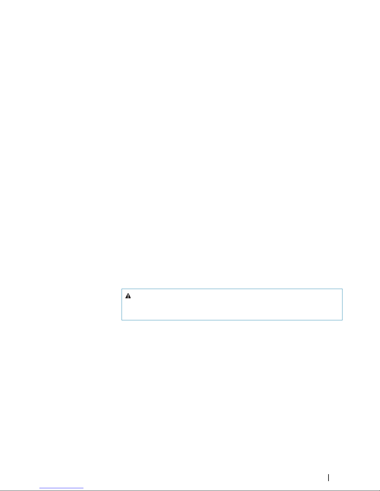
Check the contents
1
3
2
10
4
5
8
7
ENGLISH
Installa
t
ion Manua
l
E
NGLI
S
H
I
n
stalla
t
ion Manual
E
NGLISH
I
n
stalla
t
ion Manual
ENGLISH
Installation M
anua
l
6
12
13
14
11
9
1 Display unit
2 Sun cover
3 Bezel trim
4 Power cable
5 Self tapping pozi screws, 4Gx1/2” (x4 for 7", x8 for 9"/12", & x12 for 16" units)
6 Dust caps, different sizes for NMEA 2000 (x1), Ethernet (x1 for 7"/9", x2 for 12"/16")
and Sonar (x2) connectors
7 Dust cap for HDMI connector (12" and 16" only)
8 Dust cap for Video/NMEA 0183 connector
9 Dust cap for USB (16" only)
10 Document pack
11 Foam gasket (self adhesive)
12 U-bracket
13 Bracket knobs
14 Self tapping pozi screws for bracket, 14G x 1”
1
8
Check the contents | NSS evo3 Installation Manual
Page 8
Overview
The unit has a built-in CHIRP/Broadband, StructureScan and ForwardScan Echosounder.
The unit can network over NMEA 2000, and Ethernet allows access to data as well as control
of numerous optional devices that can provide Echosounder, radar, audio entertainment,
weather and digital switching.
The unit has a built-in high speed GPS receiver (10Hz) and supports Insight charts from
Navico including Insight Genesis. The system also supports charts from Navionics and C-MAP
as well as content created by a variety of third party mapping providers in the AT5 format.
The unit may be mounted to the vessel with the supplied mounting bracket, or panel
mounted.
The unit can operate on 12 V or 24 V systems.
Front controls
1
11
5
2
7
3
4
6
9
10
12
13
12
8
1 Touch screen
2 Pages/Home - press to open the Home page for page selection and setup
options
3 WheelKey - user configurable key, refer to "Configuring the WheelKey" on page 24.
Default without an autopilot connected to the system:
• Short press: toggles between panels on split screen
• Long press: maximizes active panel on split screen
Default with an autopilot connected to the system:
• Short press: opens the autopilot controller and puts the autopilot in standby
mode
• Long press: toggles between panels on split screen
4 Menu key - press to display the active panel's menu
5 Rotary knob - turn to zoom or scroll the menu, press to select an option
6 Enter key - press to select an option or to save settings
7 Exit key - press to exit a dialog, return to previous menu level, and clear the cursor
from the panel
8 MOB - press simultaneously the Enter and Exit keys to create a MOB at the
vessel's position
9 Arrow keys - press to activate the cursor or to move the cursor
Menu operation: press to navigate through menu items and to adjust a value
10 Mark key - press to place waypoint at vessel position or at cursor position when
cursor is active
11 Power key - press and hold to turn the unit ON/OFF
Press once to display the System Controls dialog, additional presses to toggle
through three default dimming levels
2
Overview | NSS evo3 Installation Manual
9
Page 9

12 Card reader door
13 Dual card reader slots
Rear connections
All units
7" and 9" units
5
6
SONAR 2
SONAR 1
POWERETHERNE
TVIDEONMEA2000
4
3
1 2
12" units
2
5
4
7
1
3
6
1
ETHERNET ETHERNET HDMI VIDEO NMEA2000
POWER SONAR 1
SONAR 2
16" units
ETHERNET
ETHERNE
T
USB
HDMI
VIDEO
NMEA2000
POWER
SONAR 1
SONAR 2
1
1
8
7 3
4
2
5
6
1 Ethernet - connection to high bandwidth network modules
2 Power - 12 V or 24 V DC supply input
3 Video - input for video sources such as cameras, and NMEA 0183 port
4 NMEA 2000 - dynamic data
5 Sonar 1 - single channel CHIRP, 50/200 kHz conventional or HDI transducer
6 Sonar 2 - singel channel CHIRP, 50/200 kHz conventional, TotalScan, StructureScan
or ForwardScan transducer
7 HDMI - video output for external monitor
8 USB - mouse, keyboard or mass storage
Card reader
Used for inserting a microSD memory card. The memory card can be used for detailed chart
data, software updates, transfer of user data, and system backup.
Ú
Note: Do not download, transfer or copy files to a chart card. Doing so can damage chart
information on the chart card.
The card reader door should always be securely shut immediately after inserting or removing
a card, in order to prevent possible water ingress.
10
Overview | NSS evo3 Installation Manual
Page 10

Installation
Mounting location
Choose the mounting locations carefully before you drill or cut.
For overall width and height requirements, refer to "Dimensional drawings" on page 51.
Do not mount any part where it can be used as a hand hold, where it might be submerged,
or where it will interfere with the operation, launching, or retrieving of the boat.
The unit should be mounted so that the operator can easily use the controls and clearly see
the screen.
The unit has a high-contrast screen and is viewable in direct sunlight, but for best results
install the unit out of direct sunlight. The chosen location should have minimal glare from
windows or bright objects.
Consider the optimum viewing angle when determining installation, refer to "Viewing angle" on
page 12.
The mounting location may affect the internal GPS receiver. Test the unit in its intended
location to ensure satisfactory reception. An external GPS source can be added to overcome
poor reception areas.
Check that it is possible to route cables to the intended mounting location.
Leave sufficient clearance to connect all relevant cables.
Before cutting a hole in a panel, make sure that there are no hidden electrical wires or other
parts behind the panel.
Ensure that any holes cut are in a safe position and will not weaken the boat’s structure. If in
doubt, consult a qualified boat builder, or marine electronics installer.
Ú
Note: Where flush mounted, the enclosure should be dry and well ventilated. In small
enclosures, it may be required to fit forced cooling.
Warning: Inadequate ventilation and subsequent overheating of the unit
may cause unreliable operation and reduced service life. Exposing the unit
to conditions that exceeds the specifications could invalidate your warranty.
– refer to "Technical specifications" on page 49.
3
Installation | NSS evo3 Installation Manual
11
Page 11
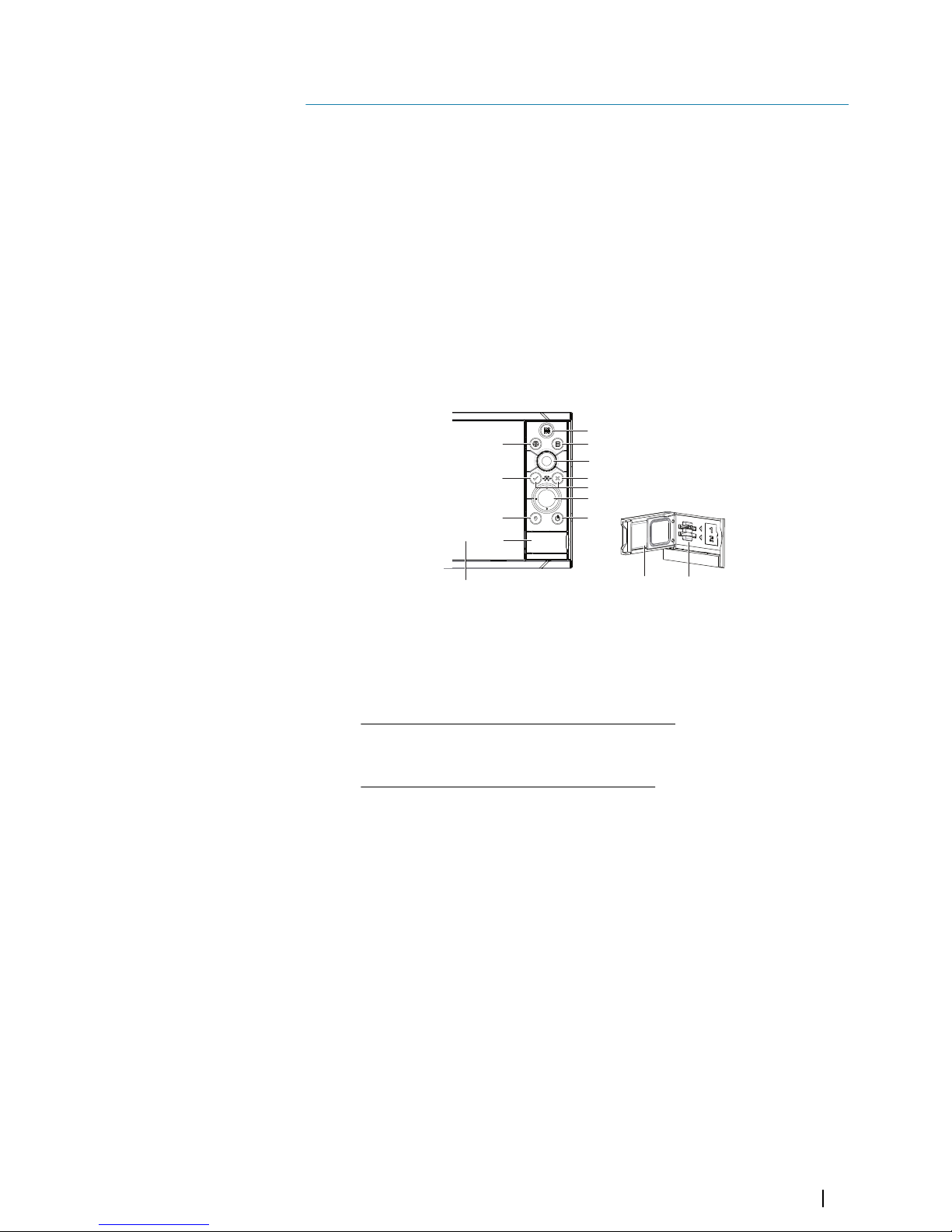
Viewing angle
The viewing angle influences the viewability of the monitor. The recommended viewing
angles relative to perpendicular are shown in the illustrations below.
A
B
B
A
80°
80
°
B B
A A
80° 80°
A Optimum viewing angle
B Poor viewing angle or obstructed view
Bracket mounting
U-bracket mounting
1. Place the bracket in the desired mounting location. Ensure that the chosen location has
enough height to accommodate the unit fitted in the bracket, and allows tilting of the
unit. Also adequate space is required on both sides to allow tightening and loosening of
the knobs.
2. Mark the screw locations using the bracket as a template, and drill pilot holes. Use
fasteners suited to the mounting surface material. If the material is too thin for selftappers, reinforce it, or mount the bracket with machine screws and large washers. Use
only 304 or 316 stainless steel fasteners.
3. Screw down the bracket.
4. Mount the unit to the bracket using the knobs. Hand tighten only. The ratchet teeth in the
bracket and unit ensure a positive grip and prevent the unit from changing from the
desired angle.
Flush mounting
Use the separate Mouting template to flush mount the unit.
Ú
Note: Remember to attach the foam gasket (self adhesive ) to rear of unit before flush
mounting.
12
Installation | NSS evo3 Installation Manual
Page 12
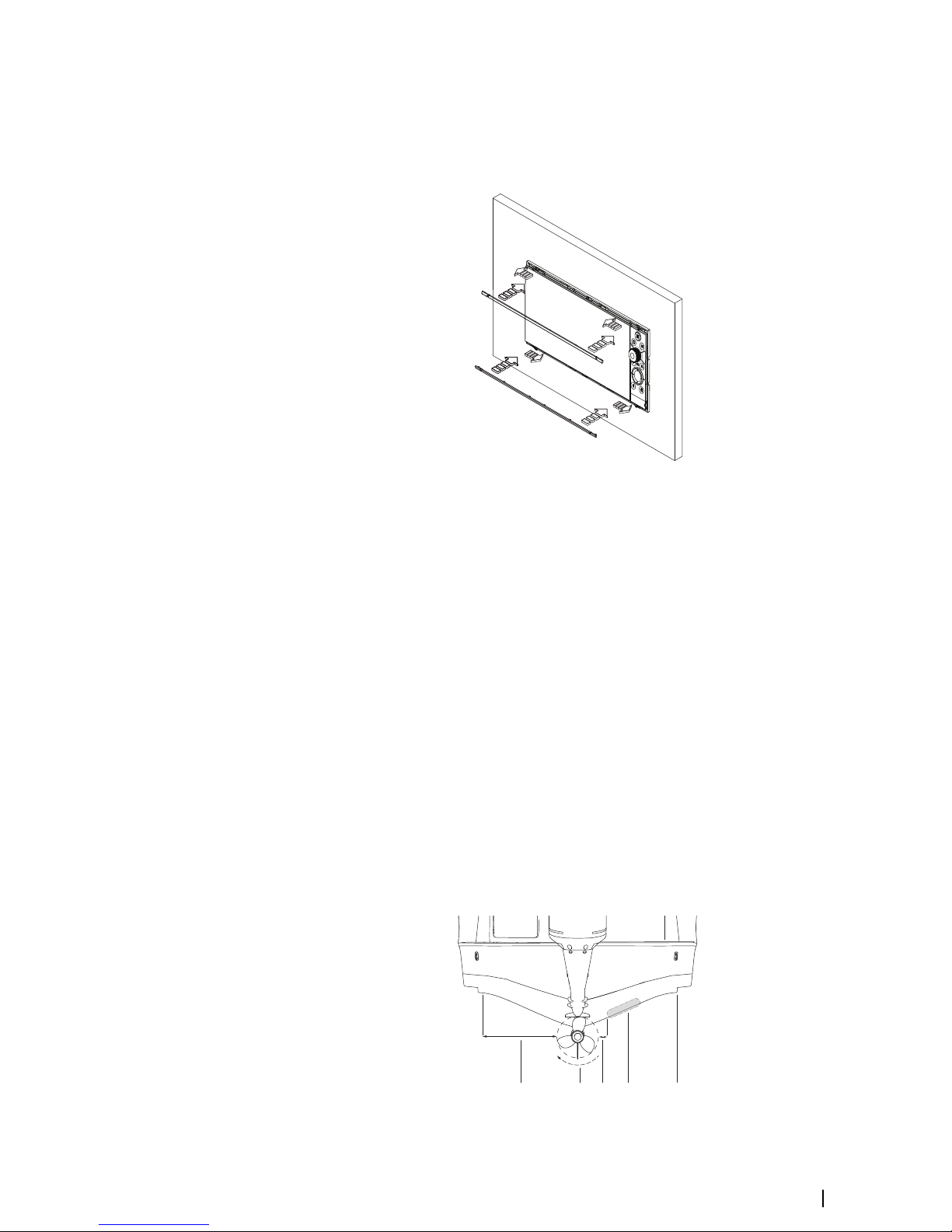
Bezel Fitment and Removal
When fitting bezels, ensure hook tabs on back of each bezel recess in to opposing slots on
screen frame. Once flush with front surface of screen, slide top bezel to the left, and bottom
bezel to the right to lock in to place.
The bezel trim have been designed to be very low profile, and therefore fully conceal the
locking tabs that keep them from being accidentally disengaged from the mounting flange.
To release the locking tab, gently lever the centre of the bezel trim away from the mounting
flange. To remove the cover, simultaneously slide it sideways; to the right for the top bezel,
and to the left for the bottom bezel.
Transducer mounting location
Transducer location selection and installation are two of the most critical steps in sonar
installation. To function properly the transducer must be in the water at all times, and in a
location that has a smooth flow of water when the boat is moving.
Research
Before starting the installation of the transducer, check the following:
• Find out if the boat builder has a recommended installation location
• Establish the direction of rotation of the propeller(s)
• With the boat traveling at cruising speed, watch the water flow behind the boat to find
the area with the smoothest flow (least bubbles)
Select a transducer location
The primary aim is to stay clear of propeller and hull generated turbulence, while mounting
the transducer as close to the center of the vessel as possible.
1
2
3
5
4
Installation | NSS evo3 Installation Manual
13
Page 13

1 Avoid mounting within 1 m (3.3’) to port (left) of propeller
2 Conventional clockwise propeller rotation
3 Avoid mounting within 7.5 cm (3“) to starboard of propeller
4 Best mounting location - undisturbed water flow
5 Planing strake - avoid mounting behind here
Ú
Note: Reverse the distance guides (1 & 3) from propeller where engine is of
counterclockwise configuration.
Ú
Note: Vessels with strakes or ribs on the hull can create large amounts of turbulence at
higher speeds. A good transducer location on these types of boats is between the ribs
closest to the engine.
Ú
Note: If the transducer is not placed in a smooth flow of water, interference caused by
bubbles and turbulence may show onscreen in the form of random lines or dots. The
unit could also lose bottom signal when the boat is on plane.
Ú
Note: Trim tabs vary in the amount of turbulence they create as they are adjusted, stay
clear of these.
Transducer installation
For transducer installation information, refer to separate installation instructions included
with the transducer.
14
Installation | NSS evo3 Installation Manual
Page 14
Wiring
Guidelines
Don't:
• make sharp bends in the cables
• run cables in a way that allows water to flow down into the connectors
• run the data cables adjacent to radar, transmitter, or large/high current carrying cables or
high frequency signal cables.
• run cables so they interfere with mechanical systems
• run cables over sharp edges or burrs
Do this:
• make drip and service loops
• use cable-tie on all cables to keep them secure
• solder/crimp and insulate all wiring connections if extending or shortening the cables.
Extending cables should be done with suitable crimp connectors or solder and heat
shrink. Keep joins as high as possible to minimize possibility of water immersion.
• leave room adjacent to connectors to ease plugging and unplugging of cables
Warning: Before starting the installation, be sure to turn electrical power
off. If power is left on or turned on during the installation, fire, electrical
shock, or other serious injury may occur. Be sure that the voltage of the
power supply is compatible with the unit.
Warning: The positive supply wire (red) should always be connected to
(+) DC with the supplied fuse or a circuit breaker (closest available to fuse
rating).
Power connection
The unit is designed to be powered by a 12 or 24 V DC system. It is protected against reverse
polarity, under voltage and over voltage (for a limited duration).
A fuse should be fitted to the positive supply; 3 A for the 7” and 9” units, and 5 A for the 12”
and 16” units.
3
4
1
2
Unit socket (male)
1
2
3
4
Cable plug (female)
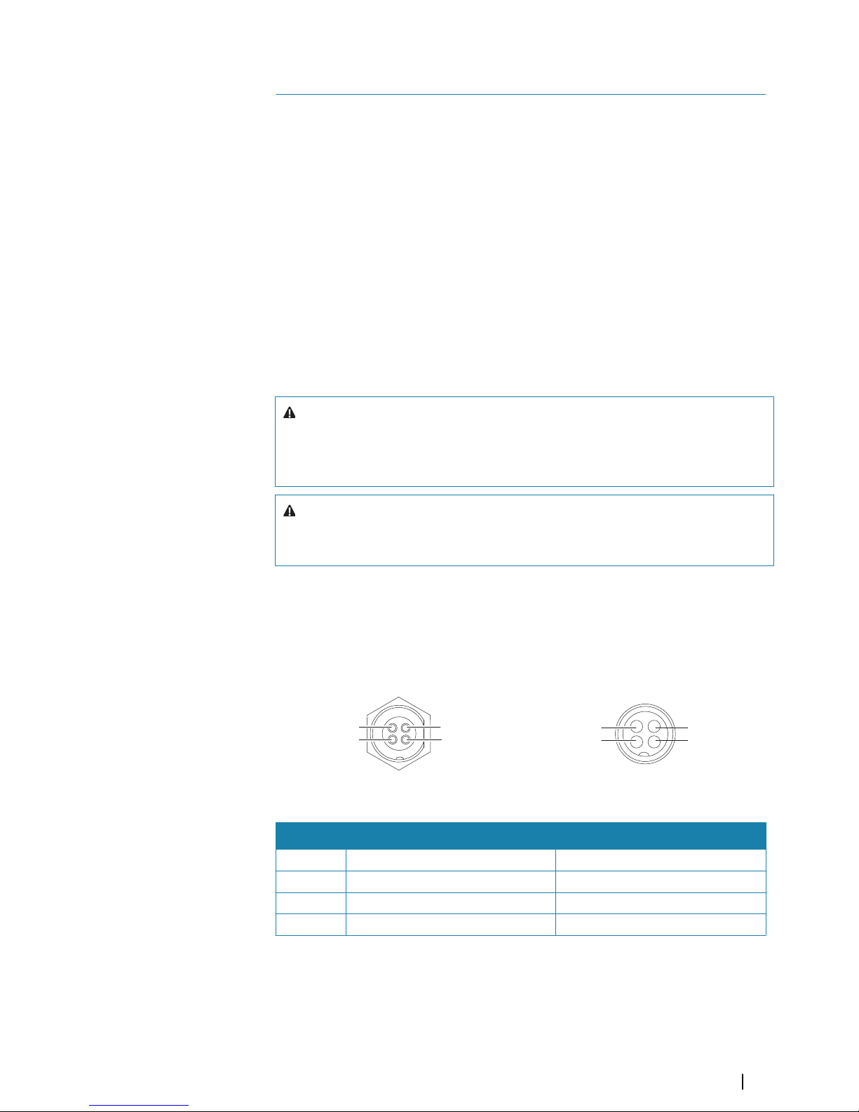
Key Purpose Color
1 DC negative Black
2 External alarm Blue
3 Power control Yellow
4 +12/24 V DC Red
Power Control connection
Ú
Note: If the control unit is set to Power Slave, the unit cannot be powered down using
its own power key. Presseing and holding this key will set the unit to standby. Refer to
"Power Control" on page 24.
4
Wiring | NSS evo3 Installation Manual
15
Page 15
The yellow Power Control wire in the power cable can either be an input that will turn on the
unit when power is applied, or an output that turns on other devices when the unit is
powered on. It can be configured at the installation stage to control the power state of
displays and compatible devices. When commissioning the system, the unit can be set to be
a Power Control Slave or Power Control Master.
Power Control configuration options of the unit are:
• Unit turns on when power key pressed: Yellow wire not connected.
• Unit turns on when power source is turned on: Common red and yellow wires.
• Unit turns on with power key, as well as other compatible devices such as Broadband
Radar: Yellow wires connected together (Power Control Bus). (Set one or more displays to
be a Power Control Master.)
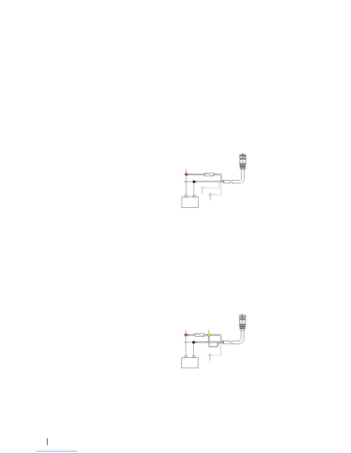
Power Control unconnected
Device will turn on and off when the power button on the front of the unit is pressed. Leave
the yellow Power Control wire disconnected and tape or heat-shrink the end to prevent
shorting.
+
_
1
2
5
4
3
1 Power cable connector to unit
2 Positive wire (red)
3 Ground wire (black)
4 Power control wire (yellow)
5 Alarm wire (blue)
Power Control to supply positive (auto on)
Device will turn on immediately when power is applied. Common the yellow wire with the
red wire after the fuse.
Ú
Note: The unit cannot be powered down by power button, but can be put in to standby
mode. (The screen backlight turns off.)
+
_
1
2
4
3
5
1 Power cable connector to unit
2 Positive wire (red)
3 Ground wire (black)
4 Power control wire (yellow)
5 Alarm wire (blue)
16
Wiring | NSS evo3 Installation Manual
Page 16
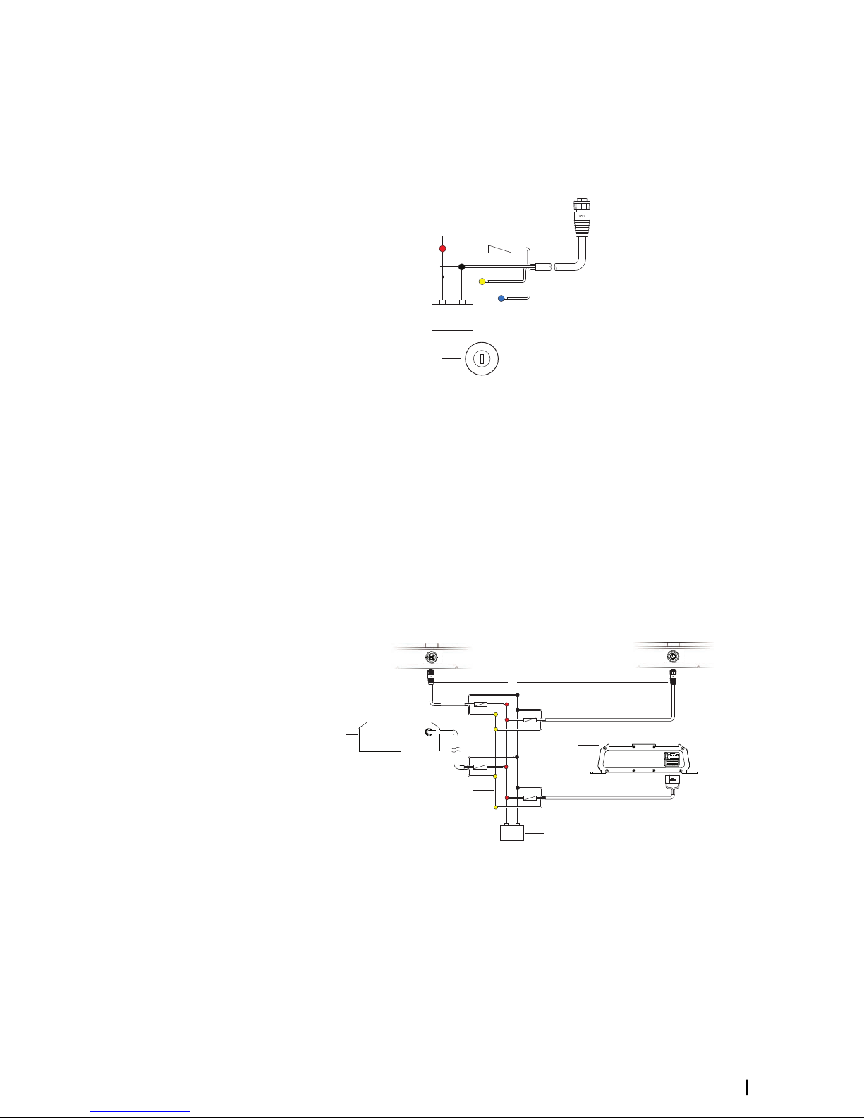
Power Control to ignition
Device will turn on once ignition is turned on to start engines. Connect the yellow wire to the
accessories output of the engine key switch.
Ú
Note: Engine start batteries and house batteries should have a common ground
connection.
+
_
5
1
2
3
4
6
1 Power cable connector to unit
2 Positive wire (red)
3 Ground wire (black)
4 Power control wire (yellow)
5 Alarm wire (blue)
6 Ignition switch
Power Control master/slave bus
Turning on the ‘master’ device turns on connected ‘slave’ devices.
+
_
5
2
1
6
7
4
3
A B
POWER
POWER
A Power connection to unit on the left
B Power connection to unit on the right
1 Power cable connectors to units
2 Radar interface box
3 Audio entertainment device (e.g. SonicHub2)
4 Ground wire (black)
5 Positive wire (red)
6 Power control wire (yellow)
Wiring | NSS evo3 Installation Manual
17
Page 17

7 DC power supply
If the unit on the left (A) is turned on using the power button and is set as the Power Control
Master, it will output voltage on the Power Control bus to power on the other unit on the
right (B), the Radar Interface, and the SonicHub.
If the unit on the right (B) is set to Power Control Slave, it cannot be powered down using its
own power button, but can be set to standby.
If the unit on the left (A) is set to Power Control Master and is off, the unit on the right (B) can
be turned on using its own power button, but does not turn on any other devices.
To turn on all network devices from either the unit on the left (A) or the unit on the right (B),
both devices can be configured as Power Control Masters.
Ú
Note: If a unit has its power state controlled by another device (or ignition switch), it
cannot be totally powered down. It can however enter a standby state to save power.
External alarm
The external alarm can be a small piezo buzzer connected directly, or a horn siren connected
through a relay.
Alarms are configured globally in the system. That is, they can be configured on any one
networked multifunction device or instrument, and be seen, heard, and acknowledged from
all devices. Individual devices can also be configured to not sound their internal buzzer, but
still display the alarm information. For information about configuring alarms, refer to the
Alarms section in the Operator Manual.
For sirens that draw more than 1 Amp, use a relay.
+
_
A
B
D
C
Buzzer
+
_
A
B
D
C
Siren
A Negative power wire (black)
B Positive power wire (red)
C Power control wire (yellow)
D Alarm wire (blue)
Connect an external monitor
The 12" and 16" units incorporate HDMI technology and have a HDMI output which can be
connected to an external monitor to replicate the display at a remote location. The image is
shown on the external monitor at the units own native resolution, so the external monitor
should support the same resolution or be able to scale.
If a monitor of different resolution is connected, a dialog is displayed at power up which
allows you to Force HDMI output to the closest resolution it can output. This may not may
provide an optimal image on the monitor. The unit will need to restart to apply the change.
Ú
Note: An HDMI cable with a water tight HDMI connector should be used to connect to
the unit in exposed installations.
Ú
Note: While the HDMI standard does not state maximum cable length, signal may be
compromised on long runs. Only use Navico or other high quality HDMI certified cables.
18
Wiring | NSS evo3 Installation Manual
Page 18

3rd party cables should be tested before installation. On runs over 10m it may be
required to add an HDMI amplifier or use HDMI-CAT6 adaptors.
Ú
Note: Some HDMI TV displays may apply over-scan, which will in effect crop the image
possibly causing loss of important content. Check the display manual for an option to
disable over-scan or adjust scaling
NMEA 2000 backbone
NMEA 2000 device connection
The NMEA 2000 data port allows the receiving and sharing of a multitude of data from
various sources.
2
1
3
4
5
Unit socket (male)
1
2
5
4
3
Cable plug (female)
Key Purpose Color
1 Shield Drain
2 NET-S (+12 V DC) Red
3 NET-C (DC negative) Black
4 NET-H White
5 NET-L Blue
Essential network information
The standardized physical cables/connectors for NMEA 2000 are Micro-C and Mini-C, directly
derived from the automation industries DeviceNET - Micro-C being the more commonly
used size.
• While most Navico products use Micro-C cabling and connectors, some products still use
proprietary SimNet connectors, which are easily made compatible with adaptor cables.
• A network consists of a linear backbone from which drop-cables connect to NMEA 2000
compliant devices.
• A single drop cable has a maximum length of 6 m (20 ft). The total length of all drop
cables combined should not exceed 78 m (256 ft).
• A NMEA 2000 network, using Micro-C cabling, has a maximum cable length of 100 m (328
ft), between any two points.
• A NMEA 2000 network needs to have a terminator at each end of the backbone. A
terminator can be one of the following:
- A terminator blank plug.
-
A wind transducer (where the mast cable is one end of the backbone).
Planning and installing a network backbone
The backbone needs to run between the locations of all products to be installed - typically in
a bow to stern layout - and be no further than 6 m from a device to be connected.
Choose from the following components to make up the backbone:
Wiring | NSS evo3 Installation Manual
19
Page 19

• Micro-C cables: 0.6 m (2 ft), 1.8 m (6 ft), 4.5 m (15 ft), and 7.6 m (25 ft) cables.
• T-connector or 4-way connector. Used to connect a drop cable to the backbone.
• Micro-C power cable. Connect to the backbone at a position that is central to the network
load using a T-connector or 4-way connector.
Power the network
The network requires its own 12 V DC power supply protected by a 5 amp fuse or breaker.
For vessels fitted with 24 V systems, use a DC-DC converter to supply 12 V.
Connect power at any location in the backbone for smaller systems.
For larger systems introduce power at a central point in the backbone to balance the voltage
drop of the network.
Ú
Note: If joining to an existing NMEA 2000 network that already has its own power
supply, do not make another power connection elsewhere in the network, and ensure
the existing network is not powered by 24 V DC.
Ú
Note: Do not connect the NMEA 2000 power cable to the same terminals as the engine
start batteries, autopilot computer, bow thruster or other high current devices.
The following drawing demonstrates a typical small network. The backbone is made up of
directly interconnected T-connectors.
+
_
12
V DC
T
3
44
6
2
1
T
5
1 NMEA 2000 device
2 Connector to unit
3 Drop-cable, should not exceed 6 m (20 ft)
4 Terminators
5 Backbone
6 Power cable
NMEA 0183 device connection
The unit has a NMEA 0183 serial port, providing both an input and an output. The port uses
the NMEA 0183 (serial balanced) standard, and can be configured in the software for different
baud rates up to 38,400 baud.
Ú
Note: The connector for NMEA 0183 is labelled VIDEO on rear of unit, as the cable is dual
purpose and carries both composite video and NMEA 0183 (on seperate wires)
20
Wiring | NSS evo3 Installation Manual
Page 20

+
+
-
-
RX_B
R
X_A
TX_B
TX_A
4
5
6
7
1
2
3
1 Connector to unit
2 Camera input 1 - red cable
3 Camera input 2 - green cable
4 NMEA 0183 RX_B (orange)
5 NMEA 0183 RX_A (green)
6 NMEA 0183 TX_B (blue)
7 NMEA 0183 TX_A (yellow)
Talkers and Listeners
Do not connect multiple devices outputting data (Talkers) on to any serial input (RX) of the
unit. The RS422 protocol is not intended for this type of connection, and data will be
corrupted if more than one device transmits simultaneously. The output (TX) however may
drive multiple receivers (Listeners). The number of receivers is finite, and depends on the
receiving hardware. Typically three devices is possible.
CZone connection to NMEA 2000
When interfacing to CZone network it is recommended to use a BEP Network interface
bridge to join the two network backbones together.
The CZone / NMEA 2000 Network interface bridge isolates the power of the two networks,
but allows data to be freely shared between both sides.
The Interface Bridge can also be used for expansion of the NMEA 2000 network, when the
maximum node limit (node = any device connected to network) for the network has been
reached or the maximum cable length of 150 m will be exceeded. Once an Interface Bridge
has been fitted, a further 40 nodes and additional cable length can be added.
The Network Interface is available from your BEP dealer.
NETWORK INTERFACE
Netw
ork 1 Network 2
CZONE
NETWORK
67$786
5HG1HWZRUN
*UHHQ1HWZRUN
CZONENMEA2000
Transducer connection
The unit has internal CHIRP, Broadband, StructureScan, TotalScan and ForwardScan sonar.
There are two 9-pin transducer connectors on the rear of the unit. Traditional 50/200 Khz,
CHIRP and HDI transducers can be connected to Sonar1 (Blue nut) or Sonar2 (black nut).
TotalScan, StructureScan and ForwardScan must be connected to Sonar2. For connector
location, refer to the embossed labeling on the back of the unit or the section "Rear connections"
on page 10.
Ú
Note: The connector attached to the transducer cable is keyed, and can only be inserted
in one orientation. Once inserted, turn locking collar to secure.
Wiring | NSS evo3 Installation Manual
21
Page 21

Ú
Note: A 7-pin transducer cable can be connected to a 9-pin port using a 7-pin to 9-pin
adaptor cable. However, if the transducer has a paddle wheel speed sensor, the waterspeed data will not be displayed on the unit.
Ú
Note: For transducer installation information, refer to separate installation instructions
included with the transducer.
Ethernet connector
The unit is equipped with an Ethernet port, which allows connecting the unit to your
network using the 5 pin Ethernet connector.
Ú
Note: The 7" and 9" units have one Ethernet port, where as the 12" and 16" have two.
Connection of network devices, such as radar, sonar, and other multifunction displays, can be
made directly to the Ethernet port, or via a network expansion device to the Ethernet port.
1
2
3
4
5
Unit socket (female)
2
3
1
4
5
Cable plug (male)
Key Purpose Color
1 Transmit positive TX+ Blue/White
2 Transmit negative TX- Blue
3 Receive positive RX+ Orange/White
4 Receive negative RX- Orange
5 Shield Bare
Ethernet expansion device
Connection of network devices can be made via an Ethernet expansion device. Additional
expansion devices can be added to provide the required number of ports.
1
3
3
3
2
1 Ethernet connector to unit
2 Ethernet expansion device
3 Network devices
22
Wiring | NSS evo3 Installation Manual
Page 22

Video in
The unit can be connected to two composite video sources, and display video images on its
display.
The video input cable is fitted with female RCA plugs - the camera cables should be
terminated with male RCA cables to suit.
Ú
Note: The video images will not be shared with another unit via the network. It is only
possible to view video on the unit connected to the video source.
Ú
Note: Both NTSC and PAL formats are supported.
1
2
3
4
A
B
VIDEO
1 Cable connector to Video port on unit
2 Camera A input (red cable)
3 Camera B input (green cable)
4 NMEA 0183 cables
Wiring | NSS evo3 Installation Manual
23
Page 23

Software Setup
This unit requires some initial configuration before use, in order to get the most out of the
product. The following sections focus on settings that typically do not require change once
configured. User preference settings and operation are covered in the Operator Manual.
Pressing the Home key or selecting the Home button opens the Home page. Select the
Settings icon in the top left corner of the Home page to open the Settings dialog and access
items that require configuration. You can also press the Power key once to display the
Systems Controls dialog and select the Settings icon from there.
First time startup
When the unit is started for the first time, or after a factory default, the unit displays a setup
wizard. Respond to the setup wizard prompts to select some fundamental setup options.
You can perform further setup using the system settings option and later change settings
made with the setup wizard.
Configuring the WheelKey
You can define what happens with a short or long press of the WheelKey on the front of the
unit.
To configure the Wheel key, select Configure WheelKey on the System Setting dialog.
Select the Short press option or Long press option in the WHEELKEY CONFIGURATION
dialog and then an option from the list displayed.
Time and Date
Configure time settings to suit vessel location, along with time and date formats.
Power Control
Determines unit response to signal applied to the yellow wire of the power cable.
Set to ‘Slave’ if the yellow wire is connected to ignition or to a stand-alone switch that applies
12 V/24 V. Set to Master to make this device turn on other devices when powered up.
Ú
Note: The System Controls panel does not display the Power Off option and you cannot
use the power key to power off the unit when the unit is configured as slave. To power
down the unit, the master device must be powered down, or system power removed.
Data source selection
Ú
Note: If NMEA 0183 is used, complete the NMEA 0183 setup prior to doing source
selection. Refer to "NMEA 0183 setup" on page 39.
Data sources provide live data to the system.
The data may originate from modules internal to the unit (for example internal GPS or sonar),
or external modules connected to the NMEA 2000 or via NMEA 0183 if available on the unit.
5
24
Software Setup | NSS evo3 Installation Manual
Page 24

When a device is connected to more than one source providing the same data, the user can
choose the preferred source. Before commencing with source selection make sure all
external devices and the NMEA 2000 backbone are connected and are turned on.
Auto Select
The Auto Select option looks for all sources connected to the device. If more than one source
is available for each data type, selection is made from an internal priority list. This option is
suitable for the majority of installations.
Manual source selection
Manual selection is generally only required where there is more than one source for the same
data, and the automatically selected source is not the one desired.
Group source selection
Multifunction displays, autopilot controllers, and instruments have the ability to:
• Use data sources (for example position, wind direction, and so on) that all other products
on the network use, or alternatively use a data source independently from other units.
• Globally change all displays over to a different source from any display. (This only includes
products set to Group mode.)
Ú
Note: In order to enable group selection, the display must be set to Simrad group.
Devices with the Group set to None can be set to use different sources to those of the rest of
the network devices.
Advanced source selection
This allows the most flexible and precise manual control over which devices provide data.
Some data sources, such as those for fuel level, or engine RPM, can only be changed from the
Advanced menu. Occasionally Auto Select may not assign the desired source, which may be
corrected using the Advanced Source Selection. An example of this is where twin
installations with NMEA 2000 compliant engines are not programmed with unique instance
numbers. This means that the auto select feature cannot determine which engine is fitted on
the port and which is fitted on the starboard side.
Ú
Note: The Advanced option is visible in multiple places - the bottom of the Sources
list, and under each source category (for example, Compass). The latter shows a filtered
list that only relates to devices that output data relevant to the category.
Software Setup | NSS evo3 Installation Manual
25
Page 25

Device list
The Device list shows the devices that provide data. This may include a module inside the
unit, or any external NMEA 2000 device.
Selecting a device in this list will bring up additional details and actions:
All devices allow allocation of an instance number in the Configure option. Set unique
instance numbers on any identical devices on the network to allow for the unit to distinguish
between them. The Data option shows all data being output by the device.
Some devices will show additional option(s) specific to the device - the RC42 illustrated
above has a Calibration option, to allow easy setup of this device.
Ú
Note: Setting the instance number on a 3rd party product is typically not possible.
SimNet Groups
The SimNet Group function is used to control parameter settings, either globally or in groups
of units. The function is used on larger vessels where several SimNet units are connected to
the network. By assigning several units to the same group, a parameter update on one unit
will have the same effect on the rest of the group members.
Display (backlighting), Units (metric or imperial units of measure), Damping (to dynamic
data), and Alarms can be grouped either in Simrad group, or groups 1 through to 6. If any
of the settings require discrete control, set it to none.
Diagnostics
The NMEA 2000 tab on the diagnostics page can provide information useful for identifying
an issue with the network.
Ú
Note: The following information may not always indicate an issue that can be simply
resolved with minor adjustment to network layout or connected devices and their
activity on the network. However, Rx and Tx errors are most likely indicating issues with
the physical network, which may be resolved by correcting termination, reducing
backbone or drop lengths, or reducing the number of network nodes (devices).
Bus state
Simply indicates whether the bus is powered, but not necessarily connected to any data
sources. However, if bus shows as off, but power is present along with an increasing error
count, it is possible that termination or cable topology is incorrect.
Rx Overflows
The unit received too many messages for its buffer before the application could read them.
Rx Overruns
The unit contained too many messages for its buffer before the driver could read them.
26
Software Setup | NSS evo3 Installation Manual
Page 26

Rx/Tx Errors
These two numbers increase when there are error messages, and decrease when messages
are received successfully. These (unlike the other values) are not a cumulative count. Under
normal operation these should be at 0. Values around 96 upwards indicate a heavily error
prone network. If these numbers go too high for a given device, it will automatically drop off
the bus.
Fast Packet Errors
Cumulative counter of any fast packet error. This could be a missed frame, or a frame out of
sequence etc. NMEA 2000 PGNs are made of up to 32 frames. The entire message will be
discarded when a frame is missed.
Ú
Note: Rx and Tx Errors often indicate an issue with the physical network, which may be
resolved by correcting termination, reducing backbone or drop lengths, or reducing the
number of network nodes (devices).
Damping
If data appears erratic or too sensitive, damping may be applied to make the information
appear more stable. With damping set to off, the data is presented in raw form with no
damping applied.
Calibration
An offset (positive or negative) can be applied to correct inaccuracies in boat speed, sea
temp, air temp, barometric pressure, and depth sourced from NMEA 2000.
Ú
Note: Any calibrations made here will ONLY be applied locally to this unit. Other devices
on the network will not have these offsets applied.
External Alarm Setup
The Siren Enabled option must be set in order for the unit to drive the buzzer when an
alarm condition arises. Its setting also determines the operation of the external alarm output.
Echosounder setup
Make general settings from the Echosounder Settings dialog. Define Echosounder sources in
the Installation dialog.
You can select which source is displayed in the Echosounder panel. You can also display two
different sources simultaneously, using a split panel configuration. All menu controls for each
panel are independent.
The source can be the internal Echosounder, another MFD on the Ethernet network, or a
Echosounder module.
Internal Echosounder
Select to make the internal Echosounder available for selection in the Echosounder menu.
For more information about panel source selection, refer to the Operator manual.
When set to off, this option disables the internal Echosounder in the unit. It will not be listed
as a Echosounder source for any unit on the network. Select this option on a unit which does
not have a transducer connected.
Network Echosounder
Enabling Network Echosounder allows the display to use other compatible Echosounder
sources on the Ethernet network as well as sharing it’s own Echosounder with other devices.
Structure depth offset
Setting for Structure transducers.
Software Setup | NSS evo3 Installation Manual
27
Page 27

All transducers measure water depth from the transducer to the bottom. As a result, water
depth readings do not account for the distance from the transducer to the lowest point of
the boat in the water or from the transducer to the water surface.
To show the depth from the lowest point of the boat to the bottom, do the following. Before
setting the Structure offset, measure the distance from the structure transducer to the lowest
point of the boat in the water. If, for example, the distance is 0.3 m (1 ft), it will be input as
(minus) - 0.3 m (-1 ft).
To show the depth from the water surface to the bottom, do the following. Before setting
the Structure offset, measure the distance from the structure transducer to the water surface.
If, for example, the distance is 0.3 m (1 ft), it will be input as (plus) 0.3 m (1 ft).
A setting of 0 (zero) causes the depth displayed to be the distance from the transducer to the
bottom.
Overlay downscan
When a DownScan source is connected to your system, you can overlay DownScan images
on the regular Echosounder image.
When activated, the Echosounder menu expands to include basic DownScan options.
Echosounder installation
Use this dialog to setup and configure available Echosounder sources.
Source
Select this option to display a list of Echosounder sources available for setup. The settings
you make in the rest of the dialog pertain to the source selected. The sources setup in this
dialog are available for selecting to display in the image in the Echosounder panel.
Search depth
Noise may cause the echosounder to search for unrealistic depths. By setting the search
depth manually the system displays echoes received from objects within the set depth
range.
Depth offset
All transducers measure water depth from the transducer to the bottom. As a result, water
depth readings do not account for the distance from the transducer to the lowest point of
the boat (for example; bottom of the keel, rudder, or skeg) in the water or from the
transducer to the water surface.
Before setting the offset, measure the distance from the transducer to the lowest point of the
boat in the water or from the transducer to the water surface.
28
Software Setup | NSS evo3 Installation Manual
Page 28

A
B
A Lowest point of vessel offset: Set the distance from the transducer to the lowest
point of the boat in the water - this should be set as a negative value. For example,
- 0.3 m (-1 ft).
B Depth below surface (waterline) offset: Set the distance from the transducer to the
surface - this should be set as a positive value. For example, +0.5 m (+1.77 ft).
For depth below transducer, set the offset to 0.
Echosounder software version
For external sounder modules, the software version is displayed in the header of the Echo
Installation dialogue. For upgrade software information, refer to "Software updates and data backup"
on page 43.
Water speed calibration
Water speed calibration is used to adjust the speed value from the paddle wheel to match
the actual boat speed through the water. Actual speed can be determined from GPS speed
over ground (SOG) or by timing the boat over a known distance. Water speed calibration
should be performed in calm conditions, with minimal wind and current movement.
Increase this value above 100 % if the paddle wheel is under reading, and decrease this value
if it is over reading. For example, if the average water speed reads 8.5 knots (9.8 MPH) and
SOG records 10 knots (11.5 MPH) the calibration value needs to be increased to 117 %. To
calculate the adjustment, divide the SOG by the paddlewheel speed, and multiply the
product by 100.
Calibration range: 50-200 %. Default is 100 %.
Water speed averaging
Averages water speed by measuring your speed at a selected interval of time. Water speed
intervals range from one to thirty seconds. For example if you select five seconds, your
displayed water speed will be based on averaging over 5 seconds of sampling.
Calibration range: 1-30 seconds. Default is 1 second.
Water temperature calibration
Temperature calibration is used to adjust the water temperature value from the sonar
transducer to match the data from another temperature sensor. It may be required to correct
for localized influences to the measured temperature.
Calibration range: -9.9° - +9.9°. Default is 0°.
Ú
Note: Water temperature calibration only appears if the transducer is temperature
capable. Check transducer type selection if this option should be available.
Transducer type
Transducer type is used for selecting the transducer model connected to the sonar module.
The transducer selected will determine what frequencies the user can select during sonar
operation. In some transducers with built-in temperature sensors, the temperature reading
Software Setup | NSS evo3 Installation Manual
29
Page 29

may be inaccurate or not available at all if the wrong transducer is selected. Transducer
temperature sensors are one of two impedances - 5k or 10k. Where both options are given
for the same model transducer, refer to paperwork supplied with transducer to determine
impedance.
ForwardScan installation
Available when the ForwardScan feature is turned on. For installation and setup information,
refer to the separate ForwardScan documentation.
StructureScan
This feature is automatically enabled when a TotalScan transducer is plugged in before the
unit has been powered on.
You should set the Structure depth offset for the structure transducer. This settings is in
the Echosounder Settings dialog.
Radar setup
Use the Radar Installation dialog to setup the radar.
Ú
Note: The installation can vary depending on the radar. Follow the installation and setup
instructions supplied with the radar.
Radar source
In a system with more than one radar, the correct device to configure can be selected from
this menu.
Ú
Note: Radars that support dual radar mode are represented twice in the source list, with
an A and B suffix.
Radar status
Scanner type
Identifies the model of scanner connected to the network.
30
Software Setup | NSS evo3 Installation Manual
Page 30

Software version
Check to make sure you have the latest software.
Serial Number
This number should be recorded for support and insurance purposes.
MARPA status
The MARPA status can identify if a heading sensor is on the network and that the radar is
receiving heading information essential for MARPA calculations.
Reset device ID
Should a radar be connected to the network that has been connected to a dual radar
network in the past, it might not be detected by the system because it might have an invalid
Device ID. With the radar connected and powered up, select the Reset Device ID button to
resolve this problem.
Ú
Note: This procedure must be performed with only one radar on the network, and only
applies where a network combines an older MFD with other MFDs.
Adjust range offset
(Pulse Radar only)
The radar sweep should commence at your vessel (a radar range of zero). You may need to
adjust the radar range offset to achieve this. If this is set incorrectly, a large dark circle in the
center of the sweep might occur. You might notice straight objects such as straight sea walls
or piers having curves or an indentation. Objects close to your vessel may appear “pulled in”
or “pushed out".
Adjust the range offset as below when the vessel is about 45 to 90 m (50 to 100 yards) from a
straight-walled jetty or similar feature that produces a straight line echo on the display.
• Point the boat towards the jetty
• Adjust the gain setting until a reasonably good image of the jetty echo is displayed
X X
Adjust antenna height
Set the radar scanner height relative to the water surface. The Radar uses this value to
calculate the correct STC settings.
Adjust bearing alignment
This is to align the heading marker on the screen with the center line of the vessel. This will
compensate for any slight misalignment of the scanner during installation. Any inaccuracy
will be evident when using MARPA or chart overlay.
Point the boat to be perpendicular to the very end of a breakwater or peninsula. Adjust the
bearing alignment setting, so that the heading marker and land mass intersect.
Sidelobe suppression
Occasionally false target returns can occur adjacent to strong target returns such as large
ships or container ports. This occurs because not all of the transmitted radar energy can be
Software Setup | NSS evo3 Installation Manual
31
Page 31

focused into a single beam by the radar antenna, a small amount energy is transmitted in
other directions. This energy is referred to as sidelobe energy and occurs in all radar systems.
The returns caused by sidelobes tend to appear as arcs.
Ú
Note: This control should only be adjusted by experienced radar users. Target loss in
harbor environments may occur if this control is not adjusted correctly.
When the radar is mounted where there are metallic objects near the radar, sidelobe energy
increases because the beam focus is degraded. The increased sidelobe returns can be
eliminated using the Sidelobe Suppression control.
By default, this control is set to Auto and normally should not need to be adjusted. However,
if there is significant metallic clutter around the radar, sidelobe suppression may need to be
increased. The control should be adjusted as follows:
1. Set Radar range to between 1/2 nm to 1 nm and Sidelobe Suppression to Auto
2. Take the vessel to a location where sidelobe returns are likely to be seen. Typically, this
would be near a large ship, container port, or metal bridge.
3. Traverse the area until the strongest sidelobe returns are seen.
4. Change Auto sidelobe suppression to OFF then select and adjust the sidelobe
suppression control until the sidelobe returns are just eliminated. You may need to
monitor 5-10 radar sweeps to be sure they have been eliminated.
5. Traverse the area again and readjust if sidelobes returns still occur.
6. Exit the dialog.
Radar sector blanking (Halo radar only)
Radar installed in close proximity to a mast or structure could cause unwanted reflections or
interference to appear on the radar image. Use the sector blanking feature to stop the radar
from transmitting on up to four sectors in the image. The blanking occurs on the main radar
PPI and on the radar overlay on a chart.
Ú
Note: Sectors are setup relative to the heading line of the radar. The bearing of the
sector is measured from the center line of the sector.
Ú
Note: Sector blanking should be applied very carefully to avoid reducing the radar’s
usefulness in identifying valid and potentially dangerous targets.
Main radar PPI Radar overlay on a chart
Adjust open array park angle (Halo Radar only)
The park angle is the final resting position of the antenna relative to the heading line of the
radar when the radar is set to standby. The antenna will stop rotating at the desired offset.
Halo light
Controls the levels of the Halo Radar pedestal blue accent lighting. There are four levels
possible for the lighting. The accent lighting can only be adjusted when the radar is in
standby mode.
Ú
Note: The blue accent pedestal lighting might not be approved for use in your boating
location. Check your local boating regulations before turning the blue accent lights ON.
32
Software Setup | NSS evo3 Installation Manual
Page 32

Adjust local interference reject
Interference from some onboard sources can interfere with the Broadband radar. One
symptom of this could be a large target on the screen that remains in the same relative
bearing even if the vessel changes direction.
Choose from Local interference rejection LOW, MED or HIGH. Default is LOW.
Restore radar to factory defaults
This option can be used to revert all user adjustments.
Video In configuration
Open the menu on the video panel to set up video.
Enable PAL or NTSC depending on the video output standard of the
selected camera.
You can optimize the video display by adjusting the video image
settings (brightness, saturation, etc.).
The settings are applied individually for each video source.
Mirror image may be applied where the camera is providing a rear
view, and the user wishes to see objects as they would appear in a
vehicle rear view mirror, i.e., on the same side as they actually are.
Autopilot setup
For setup and commissioning of autopilot computers, refer to the documentation included
with the autopilot computer.
Ú
Note: The WheelKey can be used as a STBY key when configured for autopilot control. To
configure the WheelKey, refer to "Configuring the WheelKey" on page 24.
Fuel setup
The fuel utility monitors a vessel's fuel consumption. This information is totaled to indicate
trip and seasonal fuel usage, and is used to calculate fuel economy for display on instrument
pages and the data bar.
To use the utility, a Navico Fuel Flow sensor, or a NMEA 2000 engine adaptor cable/gateway
with Navico Fuel Data Storage device must be fitted to the vessel. Neither the Navico Fuel
Flow sensor, nor the Suzuki engine interface require the use of a separate Fuel Storage
device. Refer to the engine manufacturer or dealer for information on whether or not your
engine provides a data output, and what adaptor is available to connect to NMEA 2000.
Once the physical connection is made, ensure source selection is completed. Multiple engine
installations using Fuel Flow sensors, or Fuel Data Storage devices, require setup of related
engine location in the Device list. For general source selection information, refer to "Data source
selection" on page 24.
Vessel setup
The Vessel setup dialog must be used to select the number of engines, the number of tanks
and vessel’s total fuel capacity across all tanks.
Software Setup | NSS evo3 Installation Manual
33
Page 33

Fuel remaining measurement
The Fuel remaining measurement can be determined from fuel used by engine(s), or fuel
level from tank sensors. Nominal fuel consumption is required to set the scale on the fuel
economy gauge. This value should be determined from experience, over time. Alternatively
the boat builder or designer may be able to give an approximate value to use.
Ú
Note: Fuel remaining measurement taken from level sensors while underway can get
inaccurate readings due to vessel movement.
Ú
Note: Nominal fuel consumption setting should be determined taking into account
typical vessel loads. That is, filled fuel and water tanks, stowed tender, supplies, etc.
Fuel flow configuration
After the number of engines is set, it is required to set which fuel flow sensor is connected to
which engine. Under Device list on the Network page, view the Device Configuration dialog
for each sensor, and set the Location to match the engine the device is connected to.
Unconfigure - defaults the device which clears all user settings.
Reset Fuel Flow - restores only the Fuel K-Value setting, if set in Calibrate. Only Navico
devices can be reset.
Calibrate
Calibration may be required to accurately match measured flow with actual fuel flow. Access
calibration from the Refuel dialog. Calibration is only possible on Navico’s Fuel Flow sensor.
34
Software Setup | NSS evo3 Installation Manual
Page 34

1. Start with a full tank and run the engine as it would normally be operated.
2. After at least several liters (a few gallons) have been used, the tank should be fully refilled,
and the Set to full option selected.
3. Select the Calibrate option.
4. Set the actual amount used based on amount of fuel added to the tank.
5. Select OK to save settings. The Fuel K-Value should now show a new value.
Ú
Note: To calibrate multiple engines repeat the steps above, one engine at a time.
Alternatively, run all engines simultaneously, and divide the Actual amount used by the
number of engines. This assumes reasonably even fuel consumption on all engines.
Ú
Note: The Calibrate option is only available when Set to full is selected, and a Fuel
Flow is connected and set up as a source.
Ú
Note: A maximum of 8 engines is supported using Fuel Flow sensors.
Fuel Level
With the use of a Navico Fluid Level device connected to a suitable tank level sensor, it is
possible to measure the amount of fuel remaining in any equipped tank. The number of
tanks must be set in Vessel Setup dialog, initiated from the Fuel setting options page, to
allow discrete tank assignment of the Fluid Level devices.
Select Device list on the Network page, and view the Device Configuration dialog for each
sensor, and set the Tank location, Fluid type, and Tank size.
For setting up the Instrument bar or a gauge on the Instrument page with Fluid Level device
data, refer to the Operator Manual.
Ú
Note: A maximum of 5 tanks is supported using Fluid Level devices.
Ú
Note: Tank data that is output by a compatible engine gateway can also be displayed,
however tank configuration for such a data source is not possible from this unit.
CZone setup
In order to communicate with the CZone modules connected to the network, the NSS evo3
must be assigned a unique CZone Display Dipswitch setting.
The functionality of the CZone system is determined by the CZone Config File (.zcf ), which is
stored on all CZone modules and the NSS evo3. The file is created using the CZone
Configuration Tool, a specialized PC application available from BEP Marine Ltd, and
associated CZone distributors.
The NSS evo3 system provides a means to load the Config file, as well as apply updates to
module firmware, removing the need to take a laptop computer aboard the vessel.
Enabling CZone functionality
If the CZone device(s) are not automatically detected, it is possible to manually enable
CZone.
Software Setup | NSS evo3 Installation Manual
35
Page 35

Assigning the dipswitch setting
Every product capable of controlling and viewing CZone devices must be assigned a virtual
dipswitch setting. This setting is unique for each device. Typically it is set after the
configuration file already exists on the CZone system, but it may also be set in advance. To
do so, access the CZone menu on the Settings page.
When the configuration is already available on the network, it will immediately commence
uploading to the NSS evo3 once the dipswitch is set. Allow this to complete, without
interruption.
Setting CZone to display at startup
With this option selected, the CZone control page is shown first, every time the NSS evo3 is
powered up.
CZone backlight control
Enabling this causes the NSS evo3 to synchronize its backlight setting with that of any CZone
Display Interfaces set up to share backlight settings.
Ú
Note: CZone Config also needs to have the NSS evo3 set as a controller.
Import and backup a configuration file
The files page may be used to import CZone configuration files, or export a copy to a
memory card in the card reader. Importing overwrites the existing file on the NSS evo3 and
all connected CZone devices.
For further information, see "Backing up and Importing user data" on page 44.
Wireless setup
The unit includes built-in wireless functionality that lets you:
• Use a wireless device to remotely view (smartphone and tablet) and control the system
(tablet only). Wireless devices use the GoFree app downloaded from their relevant
application store.
• Access the GoFree Shop.
• Upload your logs to create custom maps at Insight Genesis.
• Download software updates
• Connect to third party applications
Connecting a tablet
Install the GoFree App on the tablet before following this procedure.
1. Set the internal wireless to Access Point mode. To do this, select the Wireless devices
page in the Wireless settings dialog and then select the Internal wireless. Next, select the
Mode option and then select Internal Access Point.
2. Select a device on the Wireless devices page to view its network key.
3. Navigate to the wireless network connection page on the tablet, and find the unit or
GoFree wireless xxxx network. If more than one is in range, review the Wireless devices
page on the unit to confirm which wireless device is connected to the unit.
4. Enter the Network Key in the tablet to connect to the network.
36
Software Setup | NSS evo3 Installation Manual
Page 36

5. Open the GoFree application - the unit should be automatically detected. The name
displayed will be either the default, or that assigned in the Device Name setting. If the unit
does not appear, follow the on screen instructions to manually find the device.
6. Select the graphic icon of the unit. The unit displays a prompt similar to the following:
7. Select Yes for one-time connection, or Always if device is to be remembered for regular
connection. This setting can be changed later if required.
Ú
Note: The internal wireless module only supports GoFree connection to itself. Other
units connected on the network are not visible.
Connecting a smartphone
Install the GoFree App on the smartphone before following this procedure.
1. Set the internal wireless to Access Point mode. To do this, select the Wireless devices
page in the Wireless settings dialog and then select the unit's Internal Wireless. Next,
select the Mode option and then select Internal Access Point.
2. Select a device on the Wireless devices page to view its Network Key.
3. Navigate to the wireless network connection page on the smartphone, and find the unit
or GoFree wireless xxxx network. If more than one is in range, review the Wireless devices
page from the unit's Wireless settings dialog to confirm which wireless device is
connected to the unit.
4. Enter the Network Key in the smartphone to connect to the network.
5. Open the GoFree application on the smartphone, the unit should be automatically
detected. The name displayed will be either the default, or that assigned in the Device
Name setting. If the unit does not appear, follow the on screen instructions to manually
find the device.
The MFD's display is shown on the smartphone. To change the MFD's display on the
smartphone, use the MFD to change the display on the MFD. The display change on the
MFD is reflected on the smartphone.
Wireless settings
Provides configuration and setup options for the wireless functionality.
Remote controllers
When a wireless device is connected, it should appear in the Remote controllers list.
Selecting Always allow means the device can automatically connect without needing a
password each time. This menu also allows disconnection of devices that no longer require
access.
Software Setup | NSS evo3 Installation Manual
37
Page 37

Wireless devices
This dialog shows the internal wireless and any connected WIFI-1 devices, as well as their IP
and channel number. Selecting the internal wireless or a WIFI-1 device provides additional
detail.
To view and change internal wireless detail values (Network Name (SSID), Network Key, or
Channel) the internal wireless must be in Access Point (Internal Wifi) mode. To select a
network (hotspot) to connect to, the internal wireless must be in Client Mode. Use the
Mode option to change modes.
Mode
Displays if the internal wireless is set to Access Point (Internal Wifi) mode or Client Mode.
Select it to change the wireless between Access Point mode and Client Mode.
If the internal wireless is set to Access Point (Internal Wifi) mode, smartphones and tablets
can access the unit to view and control (tablet only) it. Also when set to Access Point
(Internal Wifi) mode you can view and change the internal wireless details. Client Mode
allows the unit internet access via a wireless hotspot.
When veiwing this menu for a WIFI-1 set to Access Point mode, it’s also possible to switch
between Primary and Secondary access point modes so two WIFI-1 devices can exist on
the network at the same time.
Only one WIFI-1 may operate as Primary, which determines that the device is acting as
DHCP server. Only one DHCP server may exist on a network at a time.
To use two WIFI-1s as access points simultaneously the unit must initially be connected to
only one unit. Once this unit is set to secondary, a second module may be turned on/
connected, and will automatically default to primary.
Ú
Note: In a network with only one WIFI-1 and one or more internal wireless modules, the
WIFI-1 should be left in Primary mode. The internal modules do not act as a DHCP
server.
Hardware
Provides firmware version info, and MAC address details.
Networks
Only visible if the internal wireless is in Client Mode when the device is selected. Shows a list
of all networks (hotspots) available for connection. Select the name of the desired network to
enter its network key and connect to it.
Network Name (SSID)
Displays the name of the internal wireless network.
Only visible if the internal wireless is set to Access Point (Internal Wifi) mode when the
device is selected. You can select it and change the internal wireless network to any name
you want for easy identification.
Network Key
Required by the smartphone or tablet to connect to the internal wireless network.
Only visible if the internal wireless is set to Access Point (Internal Wifi) mode when the
device is selected. You can select it and change it to increase network security. The key must
be at least 8 characters.
Channel
Only visible if the internal wireless is set to Access Point (Internal Wifi) mode when the
device is selected. Select it to change the Channel setting to overcome potential interference
to the internal wireless by another RF device transmitting in the same frequency band.
Restore defaults
Deletes all user made changes, and restores the wireless to factory settings.
38
Software Setup | NSS evo3 Installation Manual
Page 38

Client settings
Opens the Wireless Client Settings dialogue, which shows networks previously connected to,
regardless of whether they are currently visible or not. Allows deletion of a network from the
list, and toggling of Automatic connection setting.
Advanced
Tools are available within the software to assist in fault-finding and setting up the wireless
network.
Iperf
Iperf is a commonly used network performance tool. It is provided for testing wireless
network performance around the vessel so weak spots or problem areas can be identified.
The application must be installed on and run from a tablet device.
The NSS evo3 must be running Iperf server before initiating the test from the tablet. On
exiting the page, Iperf automatically stops running.
DHCP Probe
The wireless module contains a DHCP server that allocates IP addresses for all the MFDs, and
Echosounder in a network. If integrating with other devices, such as a 3G modem or satellite
phone, other devices in the network may also be acting as DHCP servers. To make it easy to
find all DHCP servers on a network, dhcp_probe may be run from the NSS evo3. Only one
DHCP device may be operational on the same network at a time. If a second device is found,
turn off its DHCP feature if possible. Refer to the device’s own instructions for further
assistance.
Ú
Note: Iperf and DHCP Probe are tools provided for diagnostic purposes by users familiar
with network terminology and configuration. Navico is not the original developer of
these tools, and cannot provide support related to their use.
Simultaneous Client and Access Point operation
If it is desirable to have the MFD accessible to a tablet while also having internet access for
GoFree store and Insight Genesis, it is necessary to use two wireless units - one must be in
Client mode, the other in Access Point mode. This can be a combination of internal wireless
and an external WIFI-1, or two external WIF-1 units. Two external WIFI-1 units will offer the
advantage of providing both features to all MFDs on the network (where applicable).visible
or not.
NMEA 0183 setup
The NMEA 0183 port must be set to suit the speed of connected devices, and can be
configured to output only the sentences required by listening devices.
Software Setup | NSS evo3 Installation Manual
39
Page 39

Receive waypoint
Select this option to allow a device capable of creating and exporting waypoints via NMEA
0183 to transfer directly to this unit.
Baud rate
This should be set to correspond with devices connected to the NMEA 0183 input and
output. The input and output (Tx, Rx) use the same baud rate setting.
Ú
Note: AIS transponders typically operate at NMEA 0183-HS (high speed), and will require
the baud rate to be set to 38,400.
Serial Output
Selection determines whether the data is output via Tx lines, and will enable editing of the
output sentences list.
Serial Output Sentences
This list allows control over which sentences need to be transmitted to other devices from
the NMEA 0183 port. Due to the limited bandwidth of NMEA 0183 it is desirable to only
enable the data that is required. The less sentences that are selected, the higher the output
rate of the enabled sentences.
Commonly used sentences are enabled by default.
40
Software Setup | NSS evo3 Installation Manual
Page 40

NMEA 0183 over Ethernet
NMEA 0183 data stream is also output over ethernet, which is made available to tablet
devices and PCs, via the internal wireless. The ethernet dialogue provides IP and port data
typically required for configuring the application on the third party device.
Ú
Note: Other MFDs cannot decode this information back to NMEA 0183, to use the data
as a source. To share data a physical NMEA 2000 or NMEA 0183 connection is still
required.
NMEA 2000 setup
Receive waypoint
Select this option to allow another device capable of creating and exporting waypoints via
NMEA 2000 to transfer directly to this unit.
Send waypoint
Select this option to allow this unit to send waypoints to another device via NMEA 2000.
Ethernet setup
No special setup is required for establishing an ethernet network, it is all plug-and-play. An
optional ethernet expansion device connected between the unit and another network
Software Setup | NSS evo3 Installation Manual
41
Page 41

module (e.g. 4G radar) will automatically start working, and relay data between the two
devices.
Diagnostics
The UDB (User Data Base) tab on the diagnostics page, provides information on Ethernet
activity, as shown below.
The Reset Display List option can be used to refresh the list of connected displays and their
UDB version.
Databases
The upper table gives an account of the various automatically synchronised databases that
ensure units are all using the same user settings and data. Each unit stores the database
locally, so that all information is available if the device is run in standalone.
Databases can become unsynchronised when one or more displays in a multi display
network are not powered up while other displays are being operated. Creation of waypoints,
routes, tracks, and altering global settings all affect databases.
When the check-box Dirty is selected, the unit has identified that its database is older than
that of another device on the network. The check-box should clear within seconds of both
devices being powered up, and the databases synchronising. If it does not clear, it is
recommended that all devices are power cycled.
IP address
The lower table shows the IP address of the display being viewed (top of list), the Master
display (with This display next to it), and any other displays in a multiple display network.
The function of the Master is invisible to the end user - It manages database synchronization,
however this task automatically shifts to another display if the current master is shut down.
The IP address list only refreshes after all devices on the network have been powered down a single device that is shutdown on the network will not be removed from the table shown
on other devices. When powering up a system that has been completely shutdown, a
network connectivity issue can be identified if a display does not show any other IP
addresses than its own.
The UDB version is dependant on the software version installed on the display. It will never
change on its own, unlike the Version of the Databases on the upper table. It is preferable to
have all UDB versions the same. This can usually be achieved by loading the latest software
on to your display - refer to "Software upgrades" on page 43.
Module network light
The network LED on network expansion devices can be useful for determining if the network
is fundamentally operational. No light indicates no connection. A rapidly blinking green LED
means the network module is communicating with another device.
42
Software Setup | NSS evo3 Installation Manual
Page 42

FLIR camera setup
The FLIR M-series cameras are plug and play when used in conjuction with the WIFI-1 acting
as a DHCP host.
Mercury®
If the unit is on the same NMEA 2000 network as a Mercury VesselView® 4, 7, 403, 502, 702,
703, or Link, a host of Mercury® specific features are automatically unlocked on the unit.
When the features are enabled, the display may prompt the user for some basic
configuration information. Refer to the VesselView® manual or engine supplier for further
information.
Suzuki Marine®
If the unit is on the same NMEA 2000 network as a Suzuki C10 color gauge, a dedicated
Suzuki instrument panel is unlocked and automatically enabled. Data source selection is
done the same way as for any regular NMEA 2000 sources.
Software updates and data backup
From time to time we release software updates to our existing products. Updates are created
for a variety of reasons; to add or improve features, to add support for new external devices,
or to fix software bugs.
When the unit is connected to the internet, a pop-up can appear advising that a software
update is available and encourages you to download the update.
The unit may be used to apply software updates to itself, and to supported network devices,
with files read off a memory card inserted in the card reader.
Before initiating an update to the unit itself, be sure to back up any potentially valuable user
data.
Network analyzer and service assistant
The system has a built-in service assistant that creates a report of the devices installed on the
NMEA 2000 and Ethernet network such as the software versions, serial numbers, and
information from the settings file to assist in technical support enquiries.
To use the analyzer, open the About page of the System settings dialog and select Support.
Two options are displayed:
Create report
Analyzes your network and prompts you for information required for support and creates the
report with information automatically gathered from the network. You can add screenshots
and log files that will be attached to the report. There is a 20MB limit for the report
attachments. You can save the report to a memory card and email it to support or upload it
directly if you have an internet connection. If you call technical support first, you can enter an
incident number to assist with tracking.
Check system for updates
Analyzes your network and checks if updates are available for compatible devices.
Ú
Note: Connect your unit to the internet to check for the latest available software
versions. The software versions will be up to date as of the last time you updated your
unit or connected to the internet.
Software upgrades
The update file must be loaded to the root directory of the memory card.
The update may be initiated at boot up: insert the memory card into the card reader before
turning the unit on, boot the unit, and follow the on-screen instructions.
Alternatively, in the Files menu, locate the update file on the memory card inserted in the
card reader and select Upgrade
, followed by This Display. Accept the prompt to reboot
Software Setup | NSS evo3 Installation Manual
43
Page 43

the unit, and wait a few moments as the unit restarts. Do not remove the memory card or
repower the unit until the process is completed (this typically takes no more than a couple of
minutes).
NMEA 2000 device upgrades
The update file must be loaded to the root directory of a memory card inserted in the card
reader.
1. Select the Files toolbar option and select the update file under Memory card.
2. Select the Upgrade option presented when the file is highlighted. A list should appear
displaying any compatible devices the update file applies to. In most cases this will be a
single device.
Ú
Note: If no device is shown, check that the device to be updated has power, and run any
outstanding updates for the unit first.
3. Select the device and initiate the upgrade. Do not interrupt the upgrade process.
Backing up and Importing user data
There are two files that can be backed up that relate to user changes made to the system:
• Waypoints, Routes, and Tracks database.
• Settings database (includes preferences such as unit settings, custom pages, and CZone
configuration files).
Insert a memory card into the unit's card reader as a storage location for backup data.
Waypoints, Routes, and Tracks database backup
You can export all Waypoints, Routes, and Tracks, or export only those contained within a
specific region.
If Export Region is selected, the chart page will be displayed, centered on vessel location.
Using the touch screen, adjust the red boundary box to outline the area to be exported. The
export option offers different file formats to save as:
• User data file version 5: Use with current units (NSO evo2/3, NSS evo2/3, NSS, NSO, NSE,
Zeus, Zeus Touch, HDS Gen2, HDS Gen2 Touch, HDS Gen3, HDS Carbon, GO XSE units,
Vulcan units, and ELITE Ti units). Offers most detail.
• User data file version 4: Use with current units (NSO evo2/3, NSS evo2/3, NSS, NSO, NSE,
Zeus, Zeus Touch, HDS Gen2, HDS Gen2 Touch, HDS Gen3, HDS Carbon, GO XSE units,
Vulcan units, and ELITE Ti units).
• User data file version 3 (with depth): Use with legacy GPS chartplotters.
• User data file version 2 (no depth): Use with legacy GPS chartplotters.
• GPX (GPS Exchange, no depth): Use with some other manufacturers’ GPS products, and
PC applications.
After you select the file type, select Export and destination memory card. The receiving
GPS/PC typically needs to be set to allow import of Waypoints.
Settings database export
Select Setting database to export the Settings database, or export CZone configuration
(CZone installation dependent). Choose the desired option and select the memory card
destination.
Importing a database
Later, if the unit has been restored to factory defaults or user data is accidentally deleted,
return to the files page, select the backed up file, and then Import. View file details for
creation date.
44
Software Setup | NSS evo3 Installation Manual
Page 44

Accessories
NSS evo3 accessories
Part number Description
000-00129-001 NSS EVO3 & ZEUS3 - VIDEO/NMEA 0183 CABLE
000-13748-001 NSS EVO3 & ZEUS3 CHART CARD DOOR
000-13740-001 NSS7 EVO3 SUN COVER
000-13741-001 NSS9 EVO3 SUN COVER
000-13742-001 NSS12 EVO3 SUN COVER
000-13743-001 NSS16 EVO3 SUN COVER
000-13749-001 NSS7 EVO3 & ZEUS3 – 7 EDGE BEZELS
000-13750-001 NSS9 EVO3 & ZEUS3 – 9 EDGE BEZELS
000-13751-001 NSS12 EVO3 & ZEUS3 – 12 EDGE BEZELS
000-13752-001 NSS16 EVO3 & ZEUS3 – 16 EDGE BEZELS
000-13753-001 NSS7 EVO3 & ZEUS3 - 7 DASH MOUNT KIT
000-13754-001 NSS9 EVO3 & ZEUS3 - 9 DASH MOUNT KIT
000-13755-001 NSS12 EVO3 & ZEUS3 - 12 DASH MOUNT KIT
000-13756-001 NSS16 EVO3 & ZEUS3 - 16 DASH MOUNT KIT
000-13757-001 NSS7 EVO3 & ZEUS3 - 7 MOUNTING BRACKET
000-13758-001 NSS9 EVO3 & ZEUS3 - 9 MOUNTING BRACKET
000-13759-001 NSS12 EVO3 & ZEUS3-12 MOUNTING BRACKET
000-13760-001 NSS16 EVO3 & ZEUS3-16 MOUNTING BRACKET
6
Accessories | NSS evo3 Installation Manual
45
Page 45

Supported data
NMEA 2000 compliant PGN List
NMEA 2000 PGN (receive)
59392 ISO Acknowledgement
59904 ISO Request
60928 ISO Address Claim
126208 ISO Command Group Function
126992 System Time
126996 Product Info
127237 Heading/Track Control
127245 Rudder
127250 Vessel Heading
127251 Rate of Turn
127257 Attitude
127258 Magnetic Variation
127488 Engine Parameters, Rapid Update
127489 Engine Parameters, Dynamic
127493 Transmission Parameters, Dynamic
127503 AC input status
127504 AC Output Status
127505 Fluid Level
127506 DC Detailed Status
127507 Charger Status
127508 Battery Status
127509 Inverter Status
128259 Speed, Water referenced
128267 Water Depth
128275 Distance Log
129025 Position, Rapid Update
129026 COG & SOG, Rapid Update
129029 GNSS Position Data
129033 Time & Date
129038 AIS Class A Position Report
129039 AIS Class B Position Report
129040 AIS Class B Extended Position Report
129041 AIS aids to Navigation
129283 Cross Track Error
129284 Navigation Data
129539 GNSS DOPs
129540 AIS Class B Extended Position Report
129794 AIS aids to Navigation
129801 Cross Track Error
129283 Cross Track Error
7
46
Supported data | NSS evo3 Installation Manual
Page 46

129284 Navigation Data
129539 GNSS DOPs
129540 GNSS Sats in View
129794 AIS Class A Static and Voyage Related Data
129801 AIS Addressed Safety Related Message
129802 AIS Safety Related Broadcast Message
129808 DSC Call Information
129809 AIS Class B “CS” Static Data Report, Part A
129810 AIS Class B “CS” Static Data Report, Part B
130074 Route and WP Service - WP List - WP Name & Position
130306 Wind Data
130310 Environmental Parameters
130311 Environmental Parameters
130312 Temperature
130313 Humidity
130314 Actual Pressure
130576 Small Craft Status
130577 Direction Data
NMEA 2000 PGN (transmit)
126208 ISO Command Group Function
126992 System Time
126996 Product Info
127237 Heading/Track Control
127250 Vessel Heading
127258 Magnetic Variation
128259 Speed, Water referenced
128267 Water Depth
128275 Distance Log
129025 Position, Rapid Update
129026 COG & SOG, Rapid Update
129029 GNSS Position Data
129283 Cross Track Error
129284 Navigation Data
129285 Route/Waypoint Data
129539 GNSS DOPs
129540 GNSS Sats in View
130074 Route and WP Service - WP List - WP Name & Position
130306 Wind Data
130310 Environmental Parameters
130311 Environmental Parameters
130312 Temperature
130577 Direction Data
Supported data | NSS evo3 Installation Manual
47
Page 47

NMEA 0183 supported sentences
TX / RX - GPS
Receive GGA GLL GSA GSV VTG ZDA
Transmit GGA GLL GSA GSV VTG ZDA GLC
TX / RX - Navigation
Receive RMC
Transmit AAM APB BOD BWC BWR
Receive
Transmit RMC RMB XTE XDR
TX / RX - Sonar
Receive DBT DPT MTW VLW VHM
Transmit DBT DPT MTW VLW VHM
TX / RX - Compass
Receive HDG HDT HDM
Transmit HDG
TX / RX - Wind
Receive MWV MWD
Transmit MWV MWD
TX / RX - AIS / DSC
Receive DSC DSE VDM
Ú
Note: AIS sentences are not bridged to or from NMEA 2000.
TX / RX - MARPA
Transmit TLL TTM
Ú
Note: These are only output sentences.
48
Supported data | NSS evo3 Installation Manual
Page 48

Technical specifications
Technical specifications
Approvals
Compliance FCC, Industry Canada, Radio Equipment
Directive, ACMA, RSM
Display
Resolution
7" unit 1024 x 600
9" unit 1280 x 720
12" unit 1280 x 800
16" unit 1920 x 1080
Type High Visibility SolarMax HD® IPS optically
bonded TFT
Brightness 1200 nits
Touch screen Full touch screen (multi-touch)
Viewing angles in degrees (typical value @
contrast ratio = 10)
80° top/bottom, 80° left/right
Electrical
Supply voltage 12/24 V DC (10 - 31.2 V DC min - max)
Power consumption - Max
7" unit 20 W +- 4 W
9" unit 23 W +- 4 W
12" unit 30 W +- 5 W
16" unit 45 W +- 5 W
Recommended fuse rating
7" unit 3 A
9" unit 3 A
12" unit 5 A
16" unit 5 A
Environmental
Operating temperature range -15°C to +55°C (5°F to 131°F)
Storage temperature -20°C to +60°C (4°F to 140°F)
Waterproof rating IPX 6 and 7
Humidity IEC 60945 Damp heat 66°C (150°F) @ 95%
relative (48 hr)
Shock and vibration 100 000 cycles of 20 G
GPS 10Hz high speed update. WASS, MSAS,
EGNOS, GLONASS
Interface/Connectivity
Ethernet
7" unit 1 Port
9" unit 1 Port
12" unit 2 Ports
8
Technical specifications | NSS evo3 Installation Manual
49
Page 49

16" unit 2 Ports
NMEA 2000 Micro-C (1)
NMEA 0183 1 input/output. 4800, 9600, 19200, 38400
baud - via optional adaptor cable
Video input 2 x Composite video RCA - via optional
adaptor cable
Data card slot 2x microSD
Wireless Internal 802.11b/g/n
Bluetooth Internal
Physical
Dimensions (W x H x D) Refer to "Dimensional drawings" on page 51
Weight (display only)
7" unit 1.1 kg (2.42 lbs.)
9" unit 1.41 kg (3.11 lbs.)
12" unit 3.1 kg (6.83lbs.)
16" unit 4.65 kg (10.25lbs.)
Compass Safe Distance - Metric, imperial 50 cm
Mounting type Bracket (Supplied) or panel mount
Autopilot
Manouveres / Turn patterns U-turn, Spiral-turn, C-turn, Zig-zag, Square-
turn, Lazy S-turn, Depth contour tracking
Steering modes Auto, Nav., No Drift, Follow up, Non-follow
up, Turn patterns, Standby, *Wind, *Wind
Nav. (*Boat type set to Sail)
Sonar
Sonar frequency 40-250kHz 455-800kHz
Sonar output power 1kW RMS
Warranty Period 3 Years
50
Technical specifications | NSS evo3 Installation Manual
Page 50

Dimensional drawings
7" Unit dimensions
263.0 mm (10.35”)
239.0 mm (9.41”)
160.3 mm (6.30”)
131.0 mm (5.15”)
(2.75”)
18.5 mm (0.73”)
70.0 mm
149.9 mm (5.90”)
248.2 mm (9.77”)
65.3 mm (2.57”)
9" Unit dimensions
310.9 mm (12.24”)
287.0 mm (11.30”)
179.5 mm (7.07”)
166.3 mm (6.55”)
131.0 mm (5.15”)
(2.74”)
18.5 mm (0.73”)
69.6 mm
66.6 mm (2.62”)
296.2 mm (11.66”)
9
Dimensional drawings | NSS evo3 Installation Manual
51
Page 51

12" Unit dimensions
377.1 mm (14.85”)
351.5 mm (13.84”)
240.6 mm (9.47”)
170.3 mm (6.70”)
78.1 mm
(3.07”)
225.3 mm (8.87”)
18.5 mm (0.73”)
349.0 mm (13.74”)
106.7 mm (4.20”)
16" Unit dimensions
462.1 mm (18.19”)
436.5 mm (17.19”)
263.9 mm (10.39”)
170.3 mm (6.70”)
79.6 mm
256.0 mm (10.08”)
434.0 mm (17.09”)
18.5 mm (0.73 ”)
(3.13”)
106.8 mm (4.21”)
Discover other marine electronics & navigation on our website.
 Loading...