

Page 1
www.simrad-yachting.com A brand by Navico - Leader in Marine Electronics
Manual
Simrad GB40
Integrated Network System
English Sw. 4
Page 2

Contents
1 Welcome to the GB40 7
1.1 Disclaimer.......................................................... 7
1.2 Warranty ...........................................................8
1.3 Terms and conventions ........................................ 8
1.4 Get Started ........................................................9
1.5 Start Up.............................................................9
1.6 Multiple panes in pages ...................................... 11
1.7 Controllers - OP30 remote/USB mouse ................. 12
1.8 Network the GB40............................................. 13
1.9 Add an OP30 to a GB40...................................... 13
2 Setup 15
2.1 Setup: Units..................................................... 15
2.2 Setup: Chart .................................................... 17
2.3 Setup: Navigation ............................................. 18
2.4 Setup: Data sources .......................................... 19
2.5 Setup: Tracks................................................... 20
2.6 Setup: Radar.................................................... 21
2.7 Setup: Echosounder .......................................... 21
2.8 Setup: AIS ....................................................... 23
2.9 Setup: Entertainment ........................................ 24
2.10 Setup: Installation........................................... 25
2.11 Setup: Vessel Statistics .................................... 27
2.12 Setup: Backup/Restore .................................... 28
2.13 Setup: System................................................ 28
2.14 Setup: Restore To Factory Defaults .................... 30
Page 3

3 Chart 31
3.1 Chart Manager.................................................. 31
3.2 Chart: The Basics.............................................. 44
3.3 Chart: Display .................................................. 45
3.4 Chart: Display features ...................................... 46
3.5 Chart: Show vessel status and position ................ 47
3.6 Chart: Position data sources ............................... 47
3.7 Chart: Instant GoTo .......................................... 47
3.8 Chart: GoTo/Show a new coordinate .................... 48
3.9 Chart: Range and bearing .................................. 48
3.10 Chart: Keep your vessel in view......................... 49
3.11 Chart: Pan the chart ........................................ 50
3.12 Chart: Zoom the chart ..................................... 50
3.13 Chart: Preset chart views ................................. 50
3.14 Chart: Orientation - Head Up/North Up/Course
Up ................................................................ 51
3.15 Chart: Vessel offset selection ............................ 52
3.16 Chart: Detail selection...................................... 52
3.17 Chart: Customise the chart screen ..................... 53
3.18 Chart: Vessel symbol selection .......................... 54
3.19 Chart: Predictor line on/off ............................... 54
3.20 Chart: Chart boundaries on/off.......................... 55
3.21 Chart: Guard zone - what is it?.......................... 55
3.22 Chart: Guard zone on/off.................................. 55
3.23 Chart: Safe depths on/off ................................. 56
3.24 Chart: Safe soundings on/off............................. 56
3.25 Chart: Light sectors on/off ................................ 57
3.26 Chart: Lat/Long grid overlay on/off .................... 57
3.27 Chart: Text on/off ........................................... 58
3.28 Chart: Preset chart views ................................. 58
Page 4

3.29 Chart: Overlays............................................... 62
3.30 Chart: Overlay the radar .................................. 63
3.31 Chart: Overlay ports & marinas ......................... 64
3.32 Chart: Overlay tide information ......................... 64
3.33 Chart: Overlay roads, terrain, bathymetry, SAR,
GMDSS .......................................................... 65
3.34 Chart: Information about an object .................... 66
3.35 Chart: Routes & waypoints ............................... 66
3.36 Chart: Create/name a new route ....................... 67
3.37 Chart: Copy a route ......................................... 68
3.38 Chart: Delete or show/hide a route .................... 68
3.39 Chart: Select & follow/stop a route .................... 69
3.40 Chart: Manage with chart ................................. 70
3.41 Chart: Manage with Routes Library .................... 71
3.42 Chart: GoTo next or previous waypoint............... 73
3.43 Chart: Reverse a route..................................... 73
3.44 Chart: Reset the XTE ....................................... 73
3.45 Chart: Tracks.................................................. 74
3.46 Chart: Tracks settings ...................................... 74
3.47 Chart: Track - show/hide.................................. 75
3.48 Chart: Manage the Track Library........................ 76
3.49 Chart: Waypoints ............................................ 77
3.50 Chart: Create a waypoint or event mark ............. 77
3.51 Chart: Edit a waypoint/event mark .................... 77
3.52 Chart: Navigate & manage your waypoints.......... 78
3.53 Chart: Manage the Waypoints Library................. 79
3.54 Chart: Cancel GoTo waypoint ............................ 79
4 3D Chart 81
4.1 3D Chart: Screen .............................................. 81
Page 5

4.2 3D Chart: Display.............................................. 82
4.3 3D Chart: Synchronize with Chart........................ 82
4.4 3D Chart: View Adjustments............................... 83
4.5 3D Chart: Bathymetrics - Show/Hide.................... 83
5 3D Steer 85
5.1 3D Steer: Display.............................................. 85
5.2 3D Steer: Reset the XTE .................................... 85
6 AIS: Introduction 87
6.1 AIS: Screen...................................................... 88
7 Echosounder 89
7.1 Echosounder: Display ........................................ 89
7.2 Echosounder: Screen......................................... 90
7.3 Echosounder: Interpret the screen....................... 91
7.4 Echosounder: Operating modes........................... 93
7.5 Echosounder: Colors.......................................... 94
7.6 Echosounder: Scroll speed.................................. 94
7.7 Echosounder: Pulse power.................................. 95
7.8 Echosounder: Gain setting.................................. 95
7.9 Echosounder: Threshold setting........................... 96
7.10 Echosounder: Noise filter.................................. 97
7.11 Echosounder: A-scope ratio .............................. 97
7.12 Echosounder: Depth line................................... 97
7.13 Echosounder: Depth value ................................ 98
7.14 Echosounder: 50/200 kHz split screen ................ 98
7.15 Echosounder: Auto Range................................. 99
7.16 Echosounder: Range ...................................... 100
7.17 Echosounder: Range shift ............................... 100
Page 6

7.18 Echosounder: Zoom range .............................. 100
7.19 Echosounder: Zoom range shift ....................... 101
7.20 Echosounder: Split zoom screen ...................... 101
7.21 Echosounder: Split bottom lock ....................... 102
7.22 Echosounder: Split ratio ................................. 103
7.23 Echosounder: A-Scope - show/hide .................. 103
8 Radar 105
8.1 Radar: Introduction ......................................... 105
8.2 Radar: Display................................................ 105
8.3 Radar: Screen ................................................ 106
8.4 Radar: Status bar............................................ 107
8.5 Radar: Operating modes - Start/Stop/Standby .... 107
8.6 Radar: Orientation - Head Up/North Up/Course
Up .............................................................. 107
8.7 Radar: Range offset (trigger delay).................... 108
8.8 Radar: PPI position - Look Ahead/Center/Offset ... 109
8.9 Radar: True or Relative Motion mode (TM/RM) .... 110
8.10 Radar: True Motion - reset TM position ............. 110
8.11 Radar: Gain, Rain clutter, Sea clutter
adjustment................................................... 111
8.12 Radar: Preferences ........................................ 114
8.13 Radar: Range & bearing ................................. 116
8.14 Radar: Targets.............................................. 121
8.15 Radar: MARPA............................................... 122
8.16 Radar: Guard zones ....................................... 126
9 Instruments 131
9.1 Instruments: Screen........................................ 131
9.2 Instruments: Display ....................................... 131
Page 7

9.3 Instruments: Configure gauge........................... 132
9.4 Instruments: New panel................................... 133
10 Entertainment 135
10.1 Entertainment: File formats supported.............. 136
10.2 Entertainment: USB drives.............................. 136
10.3 Entertainment: Video Juke Box........................ 138
10.4 Entertainment: Music Jukebox......................... 139
10.5 Entertainment: DVD/CD ................................. 143
11 Alarms 145
11.1 Alarms: Alarm Log......................................... 145
11.2 Alarms: Customize ........................................ 146
11.3 Alarms: Acknowledgement.............................. 147
12 Index 149
Page 8
1 Welcome to the GB40
The GB40 (Glass Bridge 40) system is designed for easy use in the
marine environment.
The GB40 can integrate navigation, fishfinding, instrumentation,
multimedia entertainment, and an onboard camera. Whatever type
of boat you have and however you use it, you can customize the
GB40 to meet your needs.
Flexible, modular and innovative, the GB40 delivers awesome
performance.
Please take a few minutes to learn how to get started with your
GB40.
Note: The GB40 has several requirements that must be met to
ensure safe and proper operation. Installation and interfacing o
f
the GB40 should be done by a marine technician using the
guidelines found in the various installation manuals.
1.1 Disclaimer
As Simrad is continuously improving this product, we retain the
right to make changes to the product at any time which may not
be reflected in this version of the manual. Please contact your
nearest Simrad distributor if you require any further assistance.
It is the owner’s sole responsibility to install and use the
instrument and transducers in a manner that will not cause
accidents, personal injury or property damage. The user of this
product is solely responsible for observing safe boating practices.
NAVICO HOLDING AS. AND ITS SUBSIDIARIES, BRANCHES AND
AFFILIATES DISCLAIM ALL LIABILITY FOR ANY USE OF THIS
PRODUCT IN A WAY THAT MAY CAUSE ACCIDENTS, DAMAGE OR
THAT MAY VIOLATE THE LAW.
Governing Language: This statement, any instruction manuals,
user guides and other information relating to the product
(Documentation) may be translated to, or has been translated
from, another language (Translation). In the event of any conflict
between any Translation of the Documentation, the English
language version of the Documentation will be the official version
of the Documentation.
This manual represents the product as at the time of printing.
Navico Holding AS. and its subsidiaries, branches and affiliates
reserve the right to make changes to specifications without notice.
Copyright © 2008 Navico Holding AS.
Welcome to the GB40 |7
Page 9

1.2 Warranty
The Simrad Warranty Statement is supplied as a separate
document.
It is shipped with the Product Registration Card.
In case of any queries, refer to www.simrad-yachting.com.
1.3 Terms and conventions
This manual uses the following conventions:
To "
click" on a screen feature (button, icon, text field or other)
with the OP30 means to position the cursor on a screen feature
and press the tick key.
To "
drag" over an area with the OP30 remote control means to
position the cursor on a screen feature, hold down the tick key,
then reposition the cursor.
"
Select" means to use the OP30 Remote control or USB mouse to
click on the button, key, area or point specified. For USB keyboard
operation, refer to the Controller section.
"
Select Pages" mean to select Pages on your OP30 controller
OR select
Pages on the USB mouse menu at the top of the
screen. To "
cancel" an operation means to press X on the OP30
or select "Cancel" on the main menu.
The "
main menu" refers to the buttons down the right side of
the screen. Some of these buttons display settings or values. In
some instances, the buttons referred to are actually mouse
buttons above the main pane, or shortcut buttons on the OP30.
The "
scroll frame" is the semi-transparent area framing the
chart. If you position your cursor over the edge of a scroll frame,
the chart scrolls toward the opposite edge. So, if the cursor is
positioned over the top edge, the chart scrolls from top to bottom.
A "
pane" is a part of a screen showing one GB40 function, such as
the sounder, chart, radar, and so on.
A "
page" is a full screen that might display anything from one to
four panes.
The "
cursor" is the crosshair or arrow that is shown on screen.
"Buttons" are displayed graphically on screen. They are normally
located around the screen border or in rows on the pages.
Range - enlarges the detail and Range + shrinks the detail.
8 | Welcome to the GB40
Page 10

1.4 Get Started
It's best to work through this section with the GB40 set up and
running so you can try out the various functions and see the
results.
This section assumes you have one OP30 and the master unit in
the system. It also assumes you are running from factory default
settings.
If starting the system for the first time, you're recommended to
check the setup preferences for
Units, Chart, Radar and
Echosounder. Most of these should have been set by your
system installer. See the
Setup section for more information.
It's essential that you enter accurate data to ensure the
GB40 delivers safe and reliable information.
The draft and the safe depth values must be accurate
otherwise the "Depth Below Keel" alarm will not work
correctly.
The transducer depth must be accurate otherwise the
echosounder screen will be wrong.
You are recommended to add a safety margin to these
values.
The Global Positioning System (GPS) is operated by the US
Government which is solely responsible for its operation,
accuracy and maintenance. This system is subject to
changes which could affect the accuracy and performance
of all GPS equipment in the world.
1.5 Start Up
When starting a GB40 system, perform the following common
tasks:
¾ Turn on the GB40:
• Press and hold the PWR key on the OP30 for about 5-6
seconds.
Note: If there is no OP30 connected, start the system using the
ON/OFF button at the rear of the GB40.
When the GB40 starts up, the splash screen loads followed by
the Terms & Conditions.
Welcome to the GB40 |9
Page 11

• Select
Accept conditions of use.
• If there is no GPS signal going into the GB40 an alarm may
appear. If so, select
Acknowledge.
• A full-screen
Chart pane is displayed. If you have a GPS signal
going into the system your position is centered on-screen.
¾ Start the Radar:
A radar scanner typically has a warm up period before signals can
be adequately processed.
• Select
Pages on your OP30 controller OR select Pages on
the USB mouse menu at the top of the screen. (Throughout
this manual, this action is abbreviated to "Select
Pages.")
• Select
Radar.
The Radar Mode button will display its current status.
• Select
Radar Mode if the status needs to change.
¾ Check the Instruments:
• Select Pages.
• Select
Instruments.
Your default instruments pane contains some basic information
which you can customize, depending on the sensory data your
vessel receives.
¾ Show/hide the Instruments bar:
You can show or hide the instruments bar at the bottom of the
screen.
• If you want to change the current setting, select
Pages.
• Select
Show/Hide Instruments Bar to toggle to the
other setting.
You can customize the instruments bar.
¾ Start the Echosounder:
• Select Pages.
• Select
Echo.
You can customize the
Echosounder.
¾ Select a palette:
You can select a palette to suit sunlight, day time, or night time
conditions.
10 | Welcome to the GB40
Page 12

• Select
Pages.
• The
Palette button shows the current setting. Select it to
change the setting.
• A list of choices is displayed. Select the new setting.
1.6 Multiple panes in pages
The GB40 can save and recall combinations of panes, delivering
several functions on screen at the same time. A collection of panes
is called a
Page.
Pages can be configured in several layouts:
Single - a full pane.
Twin - two half panes, side by side.
Tri - One half pane, two quarter panes.
Three-to-One - One half pane, three mini-panes.
Quad - Four quarter-panes.
¾ Loading preset panes
• Select Pages to display the single-function pages.
• Select
Pages again to display a choice of preset page
combinations tailored to suit activities such as cruising or
fishing.
• Select the page you want to display.
¾ To expand a small pane temporarily
• Press WIN on your OP30 until the pane you want to expand
has a red border.
• Select
MAX at the top right of your screen.
• Select
MIN when finished.
¾ To customize a preset page
You can select your own combination of applications to put into a
preset page.
• Select
Edit Pages.
• Select the preset page you want to edit. Select
Next.
Welcome to the GB40 |11
Page 13
• Select the layout type. Select
Next.
◦ Choose the content for each pane from the list of
applications displayed. After selecting the application for the
current highlighted pane (indicated by a red border).
Change focus to another pane by using the arrow keys on
the OP30. Once again, select an application from the list to
be displayed in this pane.
◦ Select Edit. Use the on-screen keyboard to enter a new
name. Select OK.
◦ Show or hide the instrument bar.
• Select
Save.
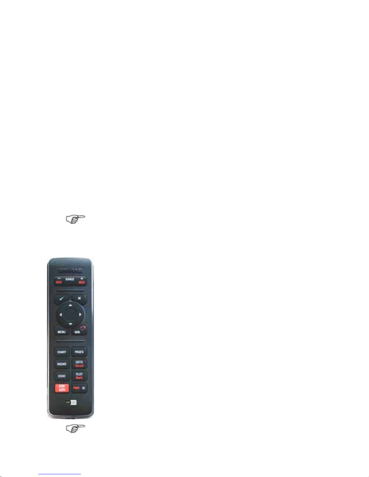
1.7 Controllers - OP30 remote/USB mouse
The GB40 can be operated using a SIMRAD OP30 remote control
(this is the preferred option) or by using a USB mouse. These
devices are called
controllers.
Note: At least one controller must be present in the network
when powered up for the first time.
OP30
The OP30 has several dedicated shortcut and feature buttons
that can access common features quickly. Each GB40 on the
network can be set up to accept or ignore key presses from any
OP30 on the network.
USB Mouse
Plugging in a USB mouse introduces an extra set of buttons on
screen.
Using a USB mouse can be a very convenient way to quickly
negotiate through the GB40s onscreen menus and buttons.
However, each mouse can only operate the GB40 it is plugged
into. The GB40 registers "left-click" or single-button clicks and
dragging, but not double-clicks.
If you're using a mouse on the same system as an OP30
controller, right click the mouse each time you use it after having
used the OP30. This will put the system back into the correct
mode for mouse usage.
Note: When a GB40 detects a mouse, an extra set of buttons
above the main pane appears. These buttons are shortcuts to
12 | Welcome to the GB40
Page 14

common functions. Right click the mouse to make it operational.
You can switch between the menu and chart cursor with a right
click (similar to the OP30 MENU key).
1.8 Network the GB40
The GB40 can be connected to a wide variety of compatible marine
devices, including Simrad's echosounder and radar. A qualified
marine electronics technician should perform these installations.
The GB40 integrated networking technology lets you connect two
or more display units in order to share navigation, sounder, radar,
entertainment, and instrumentation data. Any changes that you
make to any of these functions, such as creating a new waypoint
or saving a new video in the video jukebox, are instantly available
to everyone using the GB40 system.
If more than one display unit is used in the GB40 system, one of
them must be specified as the master unit. The other display units
are sometimes referred to as client units. The master unit MUST:
• have all the data wiring (such as NMEA) run to it. Incoming
navigation date, such as GPS and NMEA, is received by the
master unit and then distributed over the network to other
display units.
• have the chart license key connected to it. When the chart
license key is connected and the charts unlocked, other display
units can share the one license and display the charts.
• be operating in order for the other display units to function with
navigational information.
If the master unit is NOT operating, all the other display units will
show a grey screen with the message "Master “name”
unavailable". This will be the case for Chart, Radar, and 3D Chart.
1.9 Add an OP30 to a GB40
The GB40's primary controller is the Simrad OP30. Once the
SimNet network has been initialized you can add more controllers
(OP30s, a USB mouse or trackball) to the system if you want.
Networking an OP30 with a specific unit can be as simple or
detailed as you like. One GB40 can be controlled by several OP30s
or by a subset of controllers on the SimNet network but an OP30
Controller may only control a single GB40.
In multi-unit systems, setting up the master-client relationships
between the GB40s and your OP30 assignments will be done by
Welcome to the GB40 |13
Page 15

your installer but you may wish to add another OP30 to the
SimNet network at a later time.
Note: Adding a new OP30 to the SimNet network requires
another controller to be present: either an established OP30, or
a USB controller plugged into the unit that the new OP30 will
operate.
For SimNet networks with no suitable controllers attached, try
restarting the SimNet network if moored, OR, if underway,
connect an OP30 to the SimNet network. GB40 will identify with
the OP30 by sounding 3 short beeps. If the OP30 is not
recognized, press and hold the PWR and MENU keys
simultaneously for 3 seconds in order to reset the OP30.
¾ To add an OP30 to the SimNet network:
• Connect a new OP30 to the SimNet network then press and
hold the PWR and MENU keys for 5-10 seconds. A double beep
confirms that the unit has reset.
• Switch Off power on the GB40. Press and hold PWR for 5
seconds on the OP30 to switch on.
This new OP30 will register to each GB40 on the network, but
will not operate any unit until it has been assigned control.
Now use an established OP30 to assign the new OP30 to the
network as follows:
• Select
Pages, then Setup from the main menu.
• Select
Installation.
• Select
Keypad Controller Status. This page allows you to
assign the new OP30 to the target unit.
• Select the new unit's keypad ID. if you don't know which OP30
is which, select a keypad ID and select
Identify.
The targeted GB40 will send a beep and flash to the OP30
associated with the ID you selected.
Select
Add Keypad.
Select Return.
14 | Welcome to the GB40
Page 16
2 Setup
The setup options affect how the GB40 measures, displays and
interacts with the environment around your vessel.
Some setup options enable you to specify your preferences for
information display formats but other setup options are important
configurations that affect critical navigation settings.
After commissioning the system, you can record a backup on a
portable storage device.
It's essential that you enter accurate data to ensure the
GB40 delivers safe and reliable information.
Enter accurate draft and safe depth values, otherwise the
"Depth Below Keel" alarm will not work correctly.
Enter an accurate transducer depth value, otherwise the
echosounder screens will be wrong.
You are recommended to add a safety margin to this
accurate data.
¾ To access any setting:
• Select Pages then Setup from the main menu.
• Select the row showing the appropriate setting.
Options about that setting will be listed underneath.
• Select the setting you wish to change.
Depending on the setting, you might enter values using the onscreen keyboard, use a drag-line to alter values, step through
values using on-screen arrows, or use the hard-key controller.
• When you are finished, select
Return.
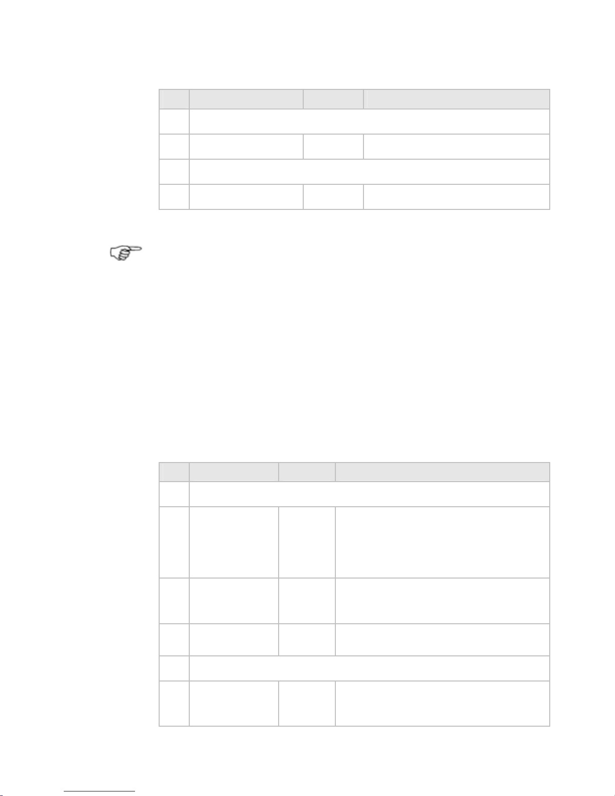
2.1 Setup: Units
¾ To enter setup options for Units
• Select Pages then Setup from the main menu.
• Select
+ Units to display a list of options.
• When you are finished, select
Return.
Setup |15
Page 17
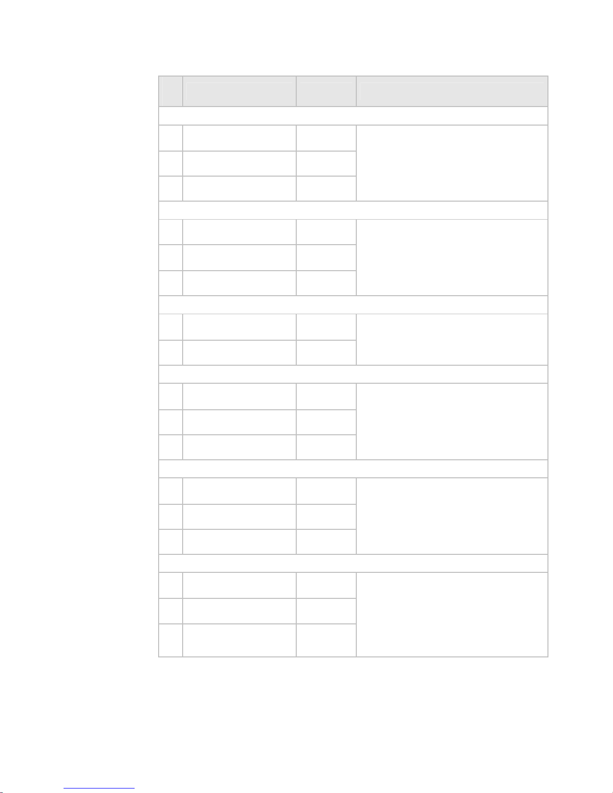
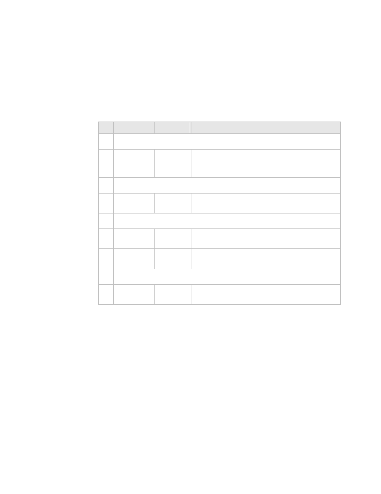
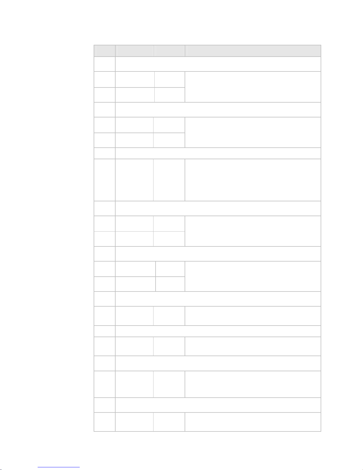
Units Default Description
Distance Units
Nautical Miles
X
Statute Miles
Kilometers
Sets the format for large distance
units.
Distance Units Small
Yards
Feet
X
Meters
Sets the format for small distance
units.
Temperature Units
Fahrenheit
X
Celsius
Sets the format for temperature
units.
Depth Units
Feet
X
Meters
Fathoms
Sets the format for depth units.
Speed Units
Knots
X
MPH
KPH
Sets the format for speed units.
Pressure Units
PSI
X
Bar
hPa
Sets the format for pressure
units.
16 | Setup
Page 18

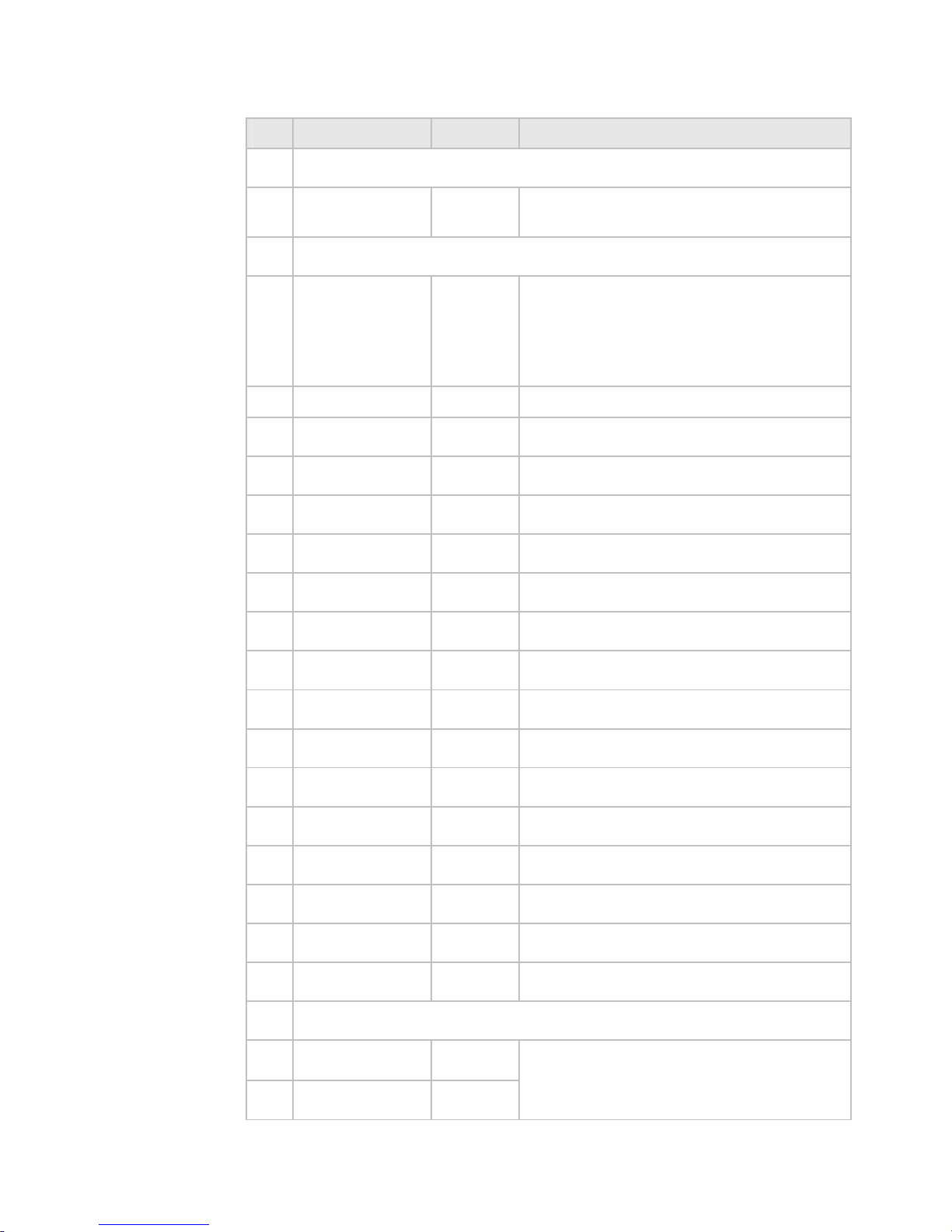
2.2 Setup: Chart
¾ To enter setup options for Chart
• Select Pages then Setup from the main menu.
• Select
+ Chart to display a list of options.
• When you are finished, select
Return.
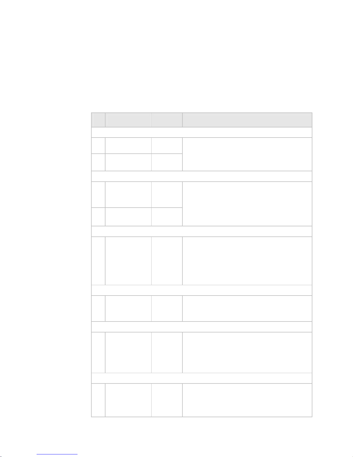
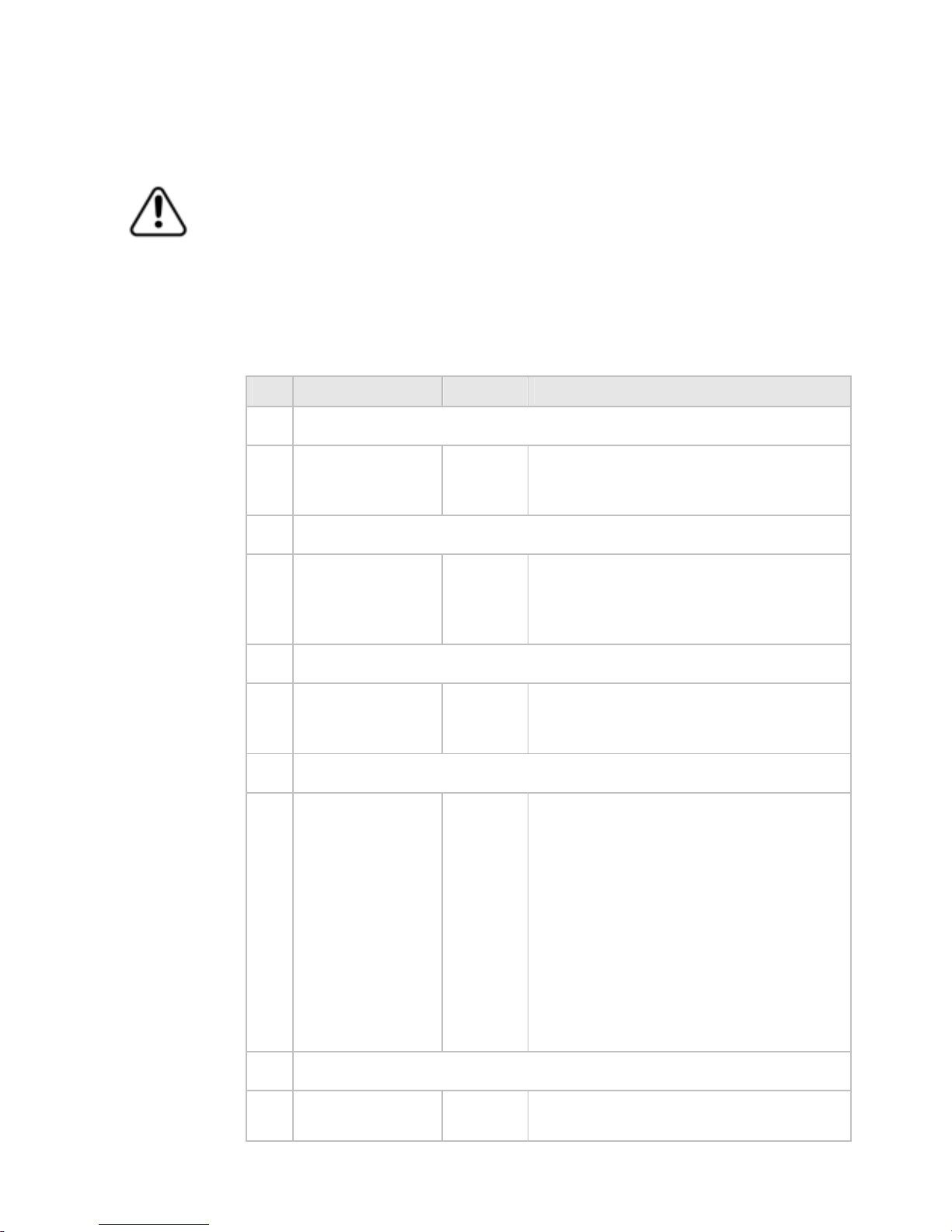
-Chart Default Description
C-Map Chart Manager
Activate
Off
Enters the C-Map Chart manager.
Use this to purchase / activate /
remove chart licenses.
C-Map Chart Diagnostics
Default Event Mark Icon
Icon Name
Sets the default for icons displayed
on the screen when the Mark button
is pressed.
Default Waypoint Icon
Icon Name
Sets the default for icons displayed
on the screen.
Guard Zone - Highlight danger objects within guard zone
On / Off
On
Sets the guard zone feature to
highlight approaching dangerous
objects on the chart.
Guard Zone angle
5,10,15,30,
45,60,75,90
15
Sets the angular width of the chart
guard zone (degrees).
Guard Zone Prediction time
1-60
minutes
5
Sets the amount of warning time
before the vessel reaches a
dangerous object.
Deep Contour
Depth Units
45 ft
Sets the value of the deep water
contour. The deep water contour
should always be deeper than the
safe depth setting.
Setup |17
Page 19
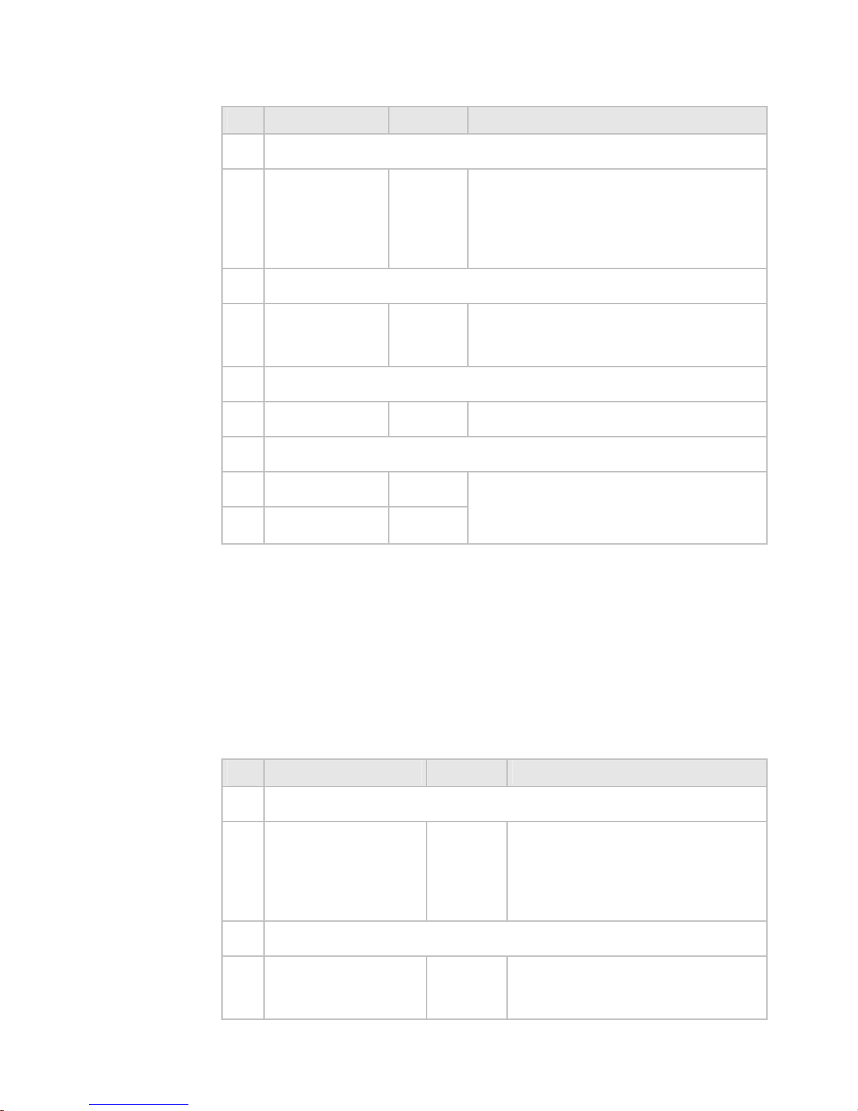
2.3 Setup: Navigation
¾ To enter setup options for Navigation
• Select Pages then Setup from the main menu.
• Select
+ Navigation to display a list of options.
• When you are finished, select
Return.
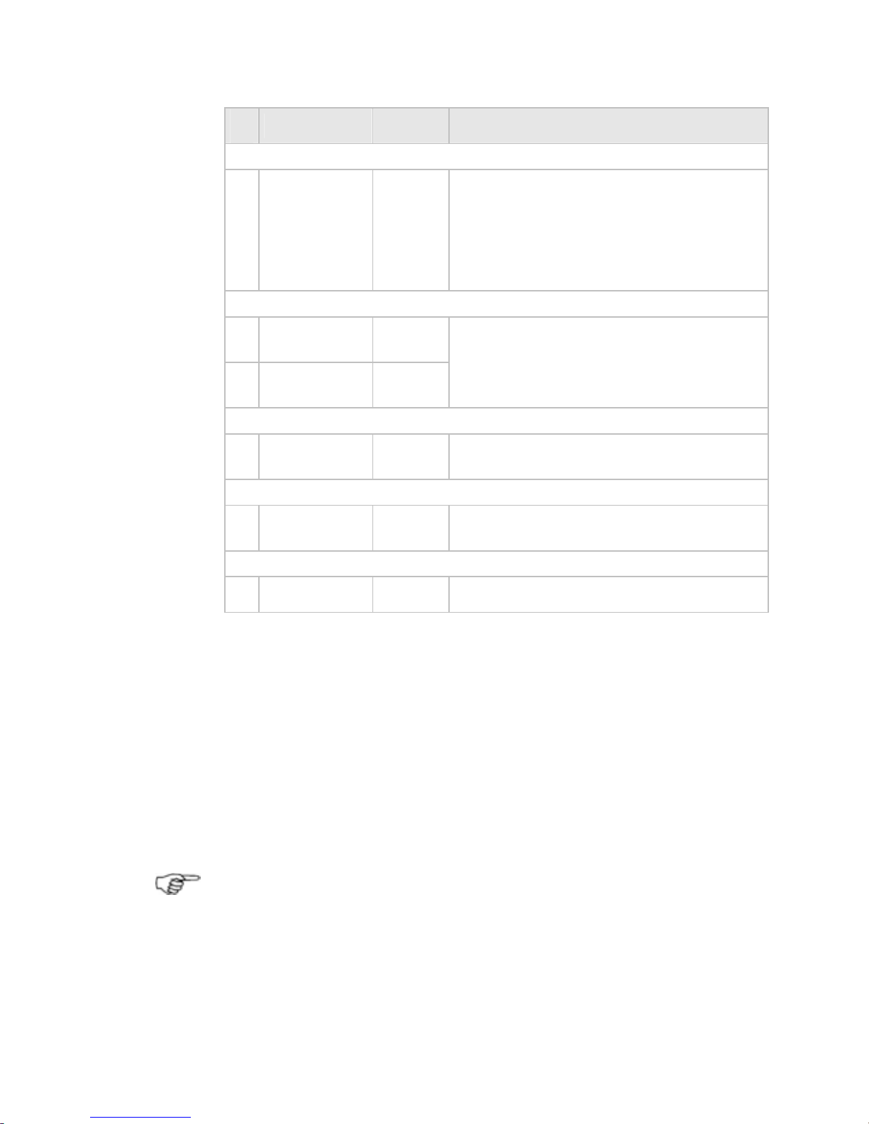
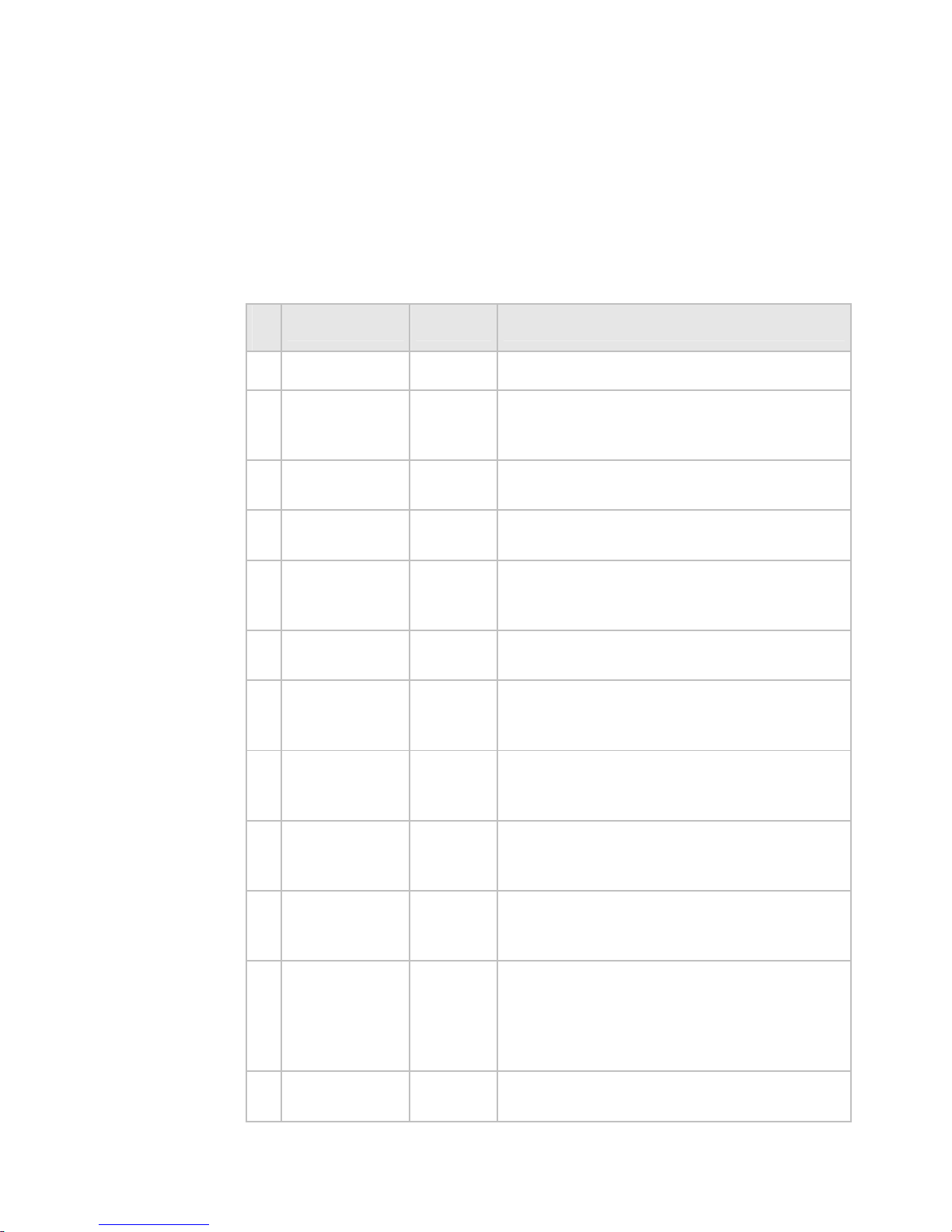
-Navigation Default Description
Bearing mode
True
X
Magnetic
Sets the mode in which all bearings are
displayed on the screen. Calculations
are made with variation taken from the
GPS.
Position Format
Degrees /
Minutes /
Seconds
Degrees /
Minutes
X
Sets the preferred format for position
data.
Predictor Length
1-60 Minutes
10
Sets how far the predictor line will
extend in front of the vessel: Predicted
position in X minutes at current speed.
Each minute is marked by a solid circle
on the course predictor line. Select Edit
to change.
Look Ahead Distance
(%)
75
Sets the amount of chart visible on the
screen in front of the vessel (Vessel
offset: look ahead mode).
Center Circle to Update
(%)
20
Sets how far the vessel will move from
center of the screen before the chart is
refreshed and the vessel returned to
center of the chart (Vessel Offset:
Center).
Angle Delay to Update
(Deg)
10
Sets the angle the vessel will turn
before the chart redraws to align vessel
with the top of the screen (Look Ahead
mode and Center mode).
18 | Setup
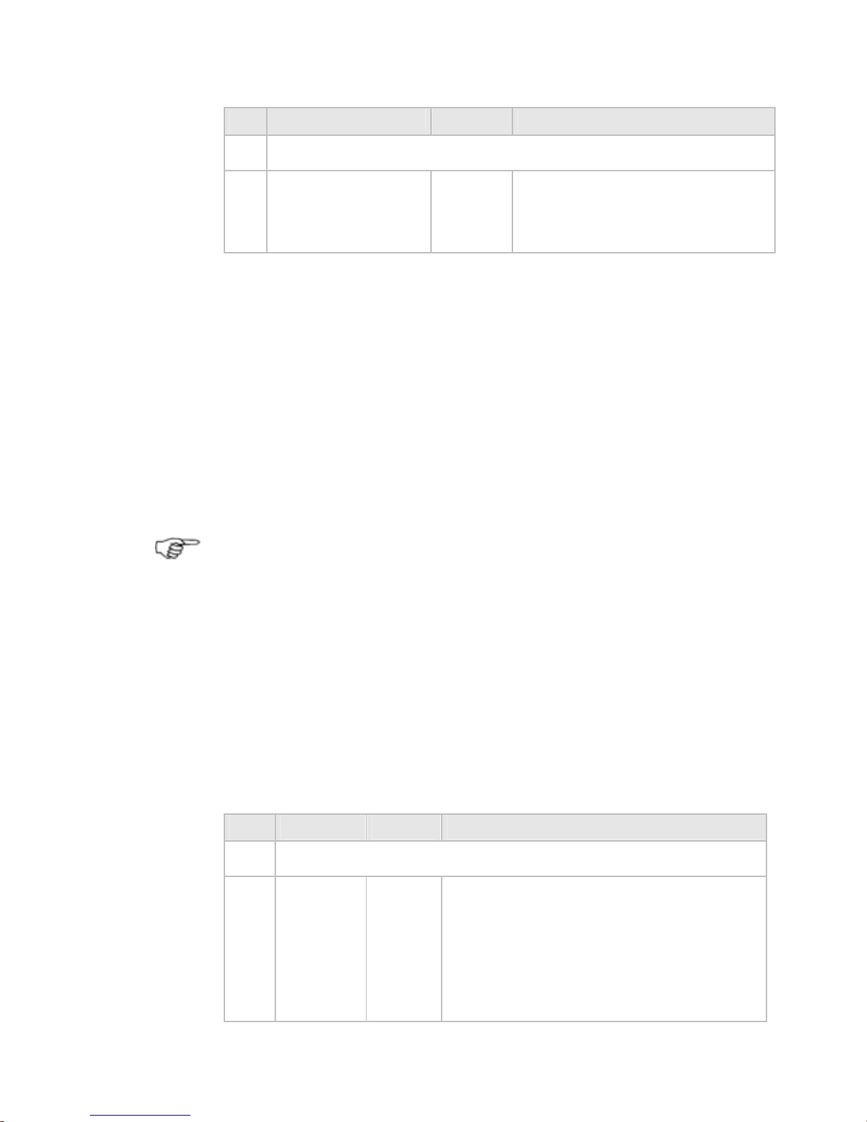
Page 20
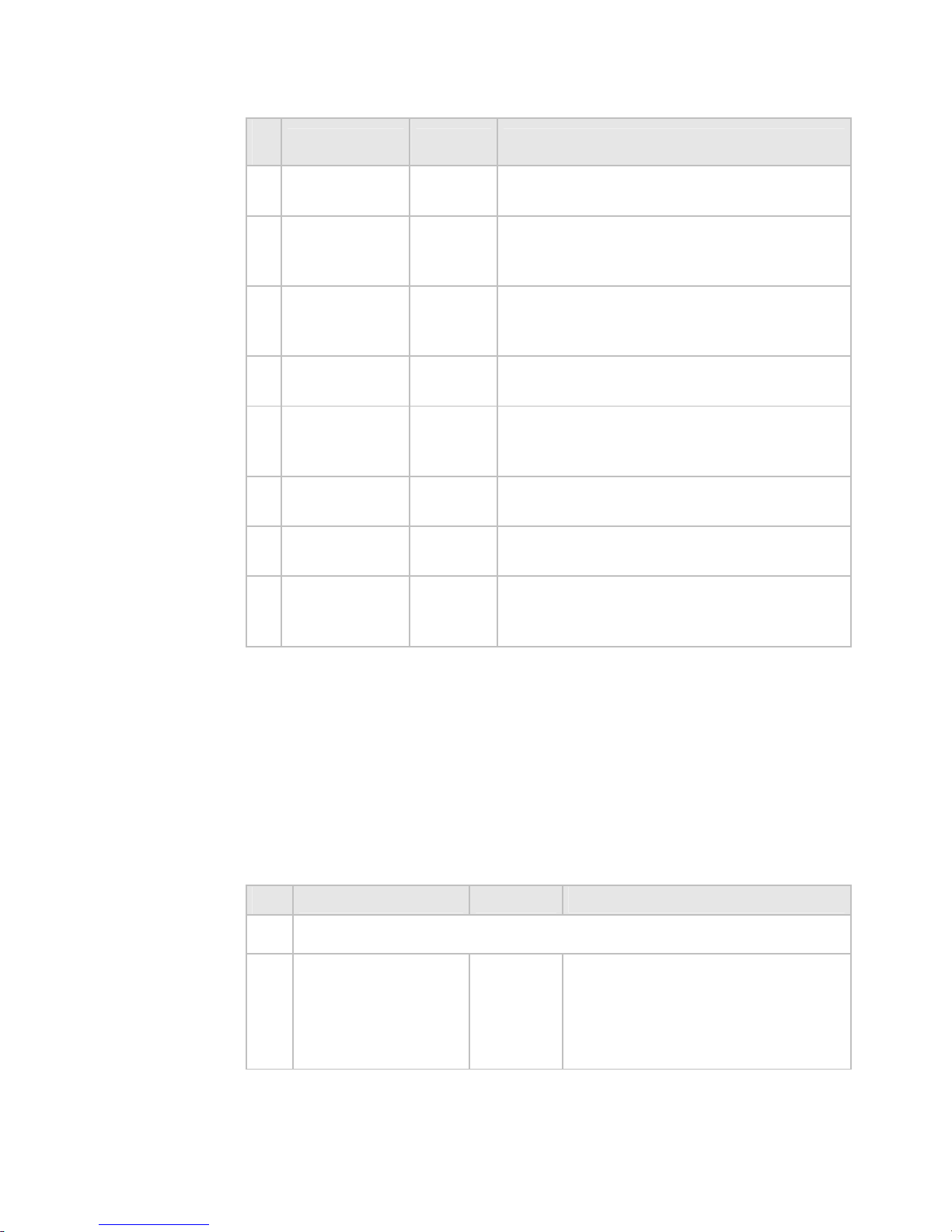
-Navigation Default Description
Waypoint Arrival Distance
(0.01-1
Nautical
Mile)
0.03
Sets the distance between the vessel
and the active waypoint before the
waypoint arrival alarm is activated and
the next waypoint becomes active.
At End of Route
Stop
Navigating
X
Keep
Navigating
Stop navigating. Cancels active route
and stops sending information to the
autopilot.
Phantom Loran
On / Off
Off
Displays Phantom Loran information on
the status bar of the chart screen.
Group Repetition Interval
(Group
Listings)
9960
Preferred TDs
None
2.4 Setup: Data sources
There are three options for selecting the data sources for the
system:
• Local Reset - data sources are set automatically for the current
display unit only.
• Global Reset - data sources are set automatically for ALL
display units in the network.
• Automatic Data Source Selection - manually initiate the auto-
matic data source selection every time the unit is powered up.
Note: Ensure that the sources of the data are connected and
powered On.
¾ To reset Data Sources Locally or Globally:
Select Pages then Setup from the main menu.
Select either
Local Reset Data Sources or Global Reset
Data Sources
depending on your requirement.
Setup |19
Page 21
¾ To select the data source for a channel where more than
one option is available:
• Select Pages then Setup from the main menu.
• Select + Data Sources to display a list of options.
• When you are finished, select
Return.
2.5 Setup: Tracks
¾ To enter setup options for Tracks
• Select Pages then Setup from the main menu.
• Select
+ Tracks to display a list of options.
• When you are finished, select
Return.
-Tracks Default Description
Record Vessel Tracks
On / Off
On
Enables the system to record the
vessel's track history.
Cross track distance to create track point
0-3000 ft
33
Sets the cross track threshold before
a track point is laid.
Distance to create track point
0.01-10 N
0.1
Sets the interval between track points
along a straight course.
Max track points shown
1,00010,000
2000
Sets the maximum amount of track
points used. After the maximum is
reached track points from the
beginning are deleted.
20 | Setup
Page 22
2.6 Setup: Radar
¾ To enter setup options for Radar
• Select Pages then Setup from the main menu.
• Select
+ Radar to display a list of options.
• When you are finished, select
Return.
- Radar Default Description
Radar Antenna Height
Small
Distance
Units
13.12 ft /
4 m
Sets the antenna height above the waterline so that the sea clutter control works
properly.
Radar Open Array Parking Angle
Deg
0
Sets the parking angle for the radar
scanner when it stops.
Radar Power on Action
Standby
X
When powered, the radar will warm up,
then go into standby mode.
Remain
Off
When GB40 is powered up, the radar will
remain Off.
Radar information
Switch
Displays magnetron hours information (for
a 10 kW or 25 kW scanner only).
2.7 Setup: Echosounder
You can:
• enter the transducer depth for your vessel
• enter an offset if you need to calibrate the water temperature
readout
• enter a filter value to average the temperature readout over a
number of readings
• select the speed offset value if you need to calibrate the
Echosounder speed
• enter a filter value to average the speed readout over a
number of readings
Setup |21
Page 23
These changes are global, meaning that they'll apply to all the
Echosounder screens.
You must enter an accurate value for the transducer depth.
If you don't, all the depths on the Echosounder screens will
be wrong.
¾ To enter setup options for Echosounder
• Select Pages then Setup from the main menu.
• Select
+ Echosounder to display a list of options.
• When you are finished, select
Return.
- Echosounder Default Description
Transducer Depth
Depth Units
0
Set the difference between the
transducer and the water line. Zero
is the water line.
Water Temperature Offset
Temperature
Units
-10 to 10
0
Set the difference between the
actual water temperature and the
one measured and displayed by the
system (if any).
Water Temperature Averaging
Seconds
2
Set the time over which the system
calculates the average temperature
before updating on the screen.
Echo Speed Offset
Speed Units
0
Set the difference between the displayed speed and the actual speed.
You'll need an accurate measurement of your vessel's speed. You can
use a GPS receiver when you're
traveling faster than 5 knots, follow
another vessel traveling at a known
speed between 5 knots and 20
knots, or make a timed run over a
known distance. Best results are
obtained in calm conditions with
minimal current.
Echo Log Speed Filter
Seconds
2
Set the average time period that the
sounder speed is updated.
22 | Setup
Page 24
2.8 Setup: AIS
¾ To enter setup options for AIS
• Select Pages then Setup from the main menu.
• Select
+ AIS to display a list of options.
• When you are finished, select
Return.
- AIS Default Description
AIS
Off
Activates AIS services.
Dangerous
vessel alarm
Off
Alarm activates when CPA is less than
the specified CPA Limit OR when TCPA is
less than the specified TCPA limit.
Lost vessel
alarm
Off
Activates when an AIS signal is no
longer received from a tracked vessel.
Proximity
alarm
Off
Activates when an AIS vessel enters the
specified proximity radius.
Show
dangerous
only
Off
Displays AIS broadcasting vessels within
the specified safe distance or on a
potential collision course.
Simulate
Off
Simulates AIS activity around around
the vessel's position.
MMSI
0
Record your vessel's MMSI number, in
order to prevent your own vessel being
displayed as a target vessel.
Proximity
Radius
(range units)
1 nm
Sets the range at which proximity
alarms activate.
TCPA limit
(1-60
minutes)
2
Time to Closest Point of Approach to the
AIS-tracked vessel at current course
and speed.
CPA limit
(range units)
0.5 nm
Distance to the AIS-vessel's Closest
Point of Approach, given current course
and speed.
AIS List
Lists all tracked AIS vessel's information
- MMSI/ Name, Position, Distance,
Bearing, Speed Over Ground, Course
Over Ground, Closest Point of Approach
and Time to Closest point of Approach.
AIS Safety
Msgs
Lists the time, MMSI and message of
broadcasting AIS vessels.
Setup |23
Page 25
- AIS Default Description
Show Vessel
by type
Hides the display of certain vessel
categories.
Filter by
distance
(range units)
Hides the display of vessels outside the
specified distance.
Filter by
speed (speed
units)
Hides the display of vessels travelling
under a certain speed.
Projected
course
Off
Displays a line indicating the course of
an AIS vessel.
Projected
Time (1 - 60
minutes)
2
Shortens or lengthens the Projected
Course line to indicate the AIS vessel's
future position given current speed.
Range Rings
0
Overlays 0-5 reference rings centered
on your vessel.
Icon Screen
Persistence
10
The time that a 'lost target' icon will be
displayed after a target is lost.
Reset To
Factory
Defaults
Initializes all variables and settings.
2.9 Setup: Entertainment
¾ To enter setup options for Entertainment
• Select Pages, then Setup from the control panel.
• Select
+ Entertainment to display a list of options.
• When you are finished, select
Return.
- Entertainment Default Description
Application Volume Levelling
Music
Video
DVD
CD
100%
Displays slider controls to adjust
individual volume levels of audio
sources.
24 | Setup
Page 26
- Entertainment Default Description
Music Library
Accesses the Music Library.
Video Library
Accesses the Video Library.
Note: When the system is installed, the Media Storage Location
needs to be set (using Setup>Installation>Change Location of
Media Storage). This tells all processors on the network which
processor is storing the music and video files. This includes
portable drives attached to the media storage location.
2.10 Setup: Installation
¾ To enter setup options for Installation
• Select Pages then Setup from the main menu.
• Select
+ Installation to display a list of options.
• When you are finished, select
Return.
- Installation Default Description
Software Version Information
Keypad
Controller
Status
Maps control devices to the GB40
being set up. You may add and
identify controllers on the network, as
well as adjust sound and backlight
levels.
Software
Version
Displays software version, firmware
version of processor and C-Map
Database version.
More info
Displays application, hardware service
and VNIB versions for diagnosis.
Network Module Firmware
Displays the firmware versions of
network modules attached to the
network.
Setup |25
Page 27
- Installation Default Description
Network Diagnostics
Displays diagnostic information
regarding the network.
Configure NMEA Output
Displays a table showing NMEA
sentences and status. Select the
desired sentence and switch On/Off
using the output button. Select Save
when finished.
Sentence Output
APA
No
APB (T)
Yes
APB (M)
No
BOD
No
BWC
Yes
DBT
No
GGA
No
GLL
Yes
HDG
No
HDT
No
RMB
Yes
RMC
Yes
VTG
Yes
XTE
Yes
ZDA
No
NMEA Baud Rate
4800
X
19200
Sets the NMEA 0183 Baud rate for
input and output.
26 | Setup
Page 28
- Installation Default Description
Change Master
Name Of
Processor
Set which unit on the network is
going to perform as the system
master. Select unit from list, press
SELECT AS MASTER then OK to
confirm.
Change Location of Media Storage
None Set None
Set
Select which processor on the
network acts as the Media Server.
Select SET LOCATION to change.
Upgrade Software
Start the software upgrade process.
Heading Priority
True
Magnetic
X
Sets the priority of the heading
source if a magnetic and true
compass are installed in the system.
2.11 Setup: Vessel Statistics
¾ To enter setup options for Vessel Statistics
• Select Pages then Setup from the main menu.
• Select
+ Vessel Statistics to display a list of options.
• When you are finished, select
Return.
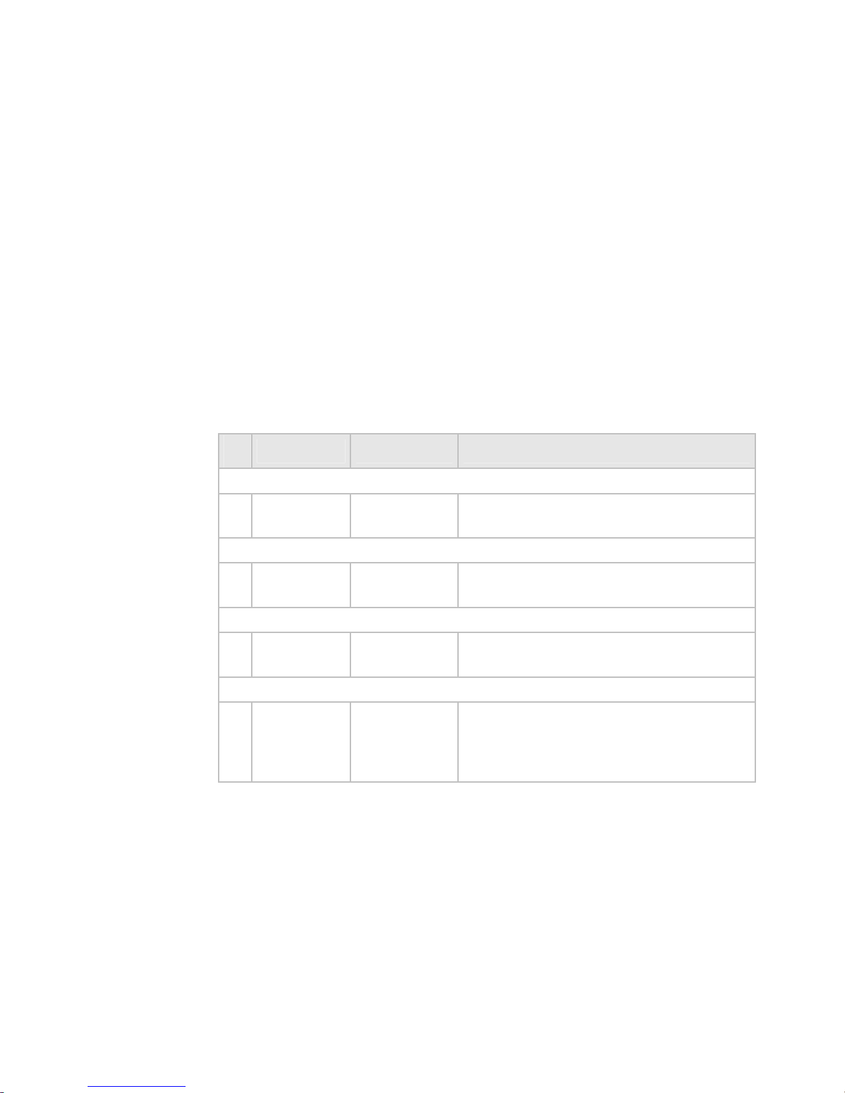
- Vessel Statistics Default Description
Cruising Speed
Speed Units
10 Knots
Set the cruising speed of the
vessel. This is used in
distance/time calculations in
Chart. Select Edit. Enter speed.
Select OK.
Draft
Depth Units
6 Feet
Set the draft of the vessel.
Used in calculating safe depths
in Chart.
Setup |27
Page 29
- Vessel Statistics Default Description
Safe Depth (Draft + Safety Margin)
Depth Units
15 Feet
Set the safe depth of water
under the keel. Used by Chart to
display safe depth contour and
safe soundings.
2.12 Setup: Backup/Restore
A removable drive must be available to either backup or restore
files.
¾ To enter setup options for Backup/Restore
• Select Pages, then Setup from the main menu.
• Select
Backup/Restore to display a list of options.
• When you are finished, select
Return.
Note: Local settings apply only to the display unit that you are
using. Global settings are applied to all the display units in
your network.
2.13 Setup: System
¾ To enter setup options for System
• Select Pages then Setup from the main menu.
• Select
+ System to display a list of options.
• When you are finished, select
Return.
- System Default Description
Processor Name
GB40
Processor
name
Re-name the processor if a more
descriptive name is needed to help
identify it on the network. Use up to 15
characters (letters and numbers only,
with no spaces). Re-select Master after
restart.
28 | Setup
Page 30
- System Default Description
Language
English US
X
English UK
Set the preferred language.
Decimal Separator
Point
X
Comma
Used to select separator between values
e.g. Long/Latitude.
Select Time Zone
Selected
Time
Zone
GMT
Set the local time zone. Allow for
daylight saving if applicable. Select from
the list of time zones. Press select time
zone to confirm. Check local time (this is
displayed in the Position screen).
Time Format
12
X
24
Set the preferred time format for time
display.
Date Format
MM/DD/YY
X
DD/MM/YY
Set the preferred format for date
display.
Display One Backlight Level
(0-100)
100
Controls the backlight levels of the
various display units.
Display Two Backlight Level
(0-100)
100
Controls the backlight levels of the
various display units.
Restart Software
Restarts the application software. Not a
system restart. Takes around 15
seconds.
Synchronize Time
Synchronizes the processor system time
with the time coming from the GPS.
Setup |29
Page 31

- System Default Description
Data Channel Diagnostics
Channels snapshot dialog page.
2.14 Setup: Restore To Factory Defaults
Navigation Data will be lost when GB40 is restored to
Factory Defaults. You are recommended to perform a
backup before taking this action.
¾ To enter setup options for Restore To Factory Defaults
• Select Pages then Setup from the main menu.
• Select
Restore To Factory Defaults to display a list of
options.
• When you are finished, select
Return. The restored nodes will
be restarted.
30 | Setup
Page 32

3 Chart
The GB40 is supplied with default settings for all the
Chart options,
but you can change many of the settings to suit your own
preferences. You can:
• set up your Chart Library
• change your
Chart settings
• show and hide items on your Chart
• store your settings as Chart views
• choose which
Chart overlays to use
• change the navigation settings
• change the tracks settings
• import waypoints and routes from an older Simrad system
Each of these sections summarizes the settings that you can
change, and explains how to change each setting.
The electronic chart used by the Simrad GB40 is an aid to
navigation designed to supplement, not replace, official
government charts. Only official government charts
supplemented by notices to mariners contain the
information required for safe and prudent navigation.
Always supplement the electronic information provided by
the Simrad GB40 with other plotting sources such as
observations, depth soundings, radar and hand compass
bearings. Should the information not agree, the discrepancy
must be resolved before proceeding any further.
3.1 Chart Manager
If you're running a networked GB40 system on your vessel, be
sure to unlock the chart collection on the master unit. Then, when
the master unit is On, the chart collections are available to all the
other display units on your GB40 network.
Use the Chart Manager to:
• purchase a license and/or subscription for one or more chart
collections
• install the chart collections into the Chart Library
• update charts over the internet then install the updates into the
Chart Library
Chart |31
Page 33

• update the database using a DVD with the updated database
from a C-Map office or from an authorized C-Map dealer
• download chart updates over the internet using a USB drive if
you've paid for a subscription (the first year's subscription is
free).
You need a valid license for each chart before you can install new
charts to a chart collection.
BEFORE connecting or using a USB drive, CD or other
removable media to the GB40, check it for viruses or
corrupt data on a device isolated from the GB40 system.
Chart Manager: License and subscription options
The Chart Library uses charts supplied by C-Map. Charts are
grouped together into collections that cover various regions of the
world.
All of the C-Map chart collections are pre-loaded into the GB40.
You must purchase a license then unlock the code for each chart
collection that you want to use, and then update this license
annually.
A subscription to the chart updates is included free with the first
year's license, and you can update this annually if you want to
maintain your subscription.
You can purchase the licenses and subscriptions in three ways:
• through your dealer
• over the phone
• over the internet
The information about your licenses and subscriptions is stored on
your Chart License Key.
Purchase or Rent?
If you purchase a chart collection, it's always available.
Additionally, you can install any updates to the chart databases
that C-Map issue within a one-year period after purchase at no
extra cost.
After that one-year period you can choose whether or not to
subscribe to further updates on an annual basis.
If you rent a chart collection, it's available for a four-month period.
32 | Chart
Page 34

Chart Manager: Display information
The C-MAP PRO Chart Manager screen shows:
• the hardware key serial number
• version number of the Chart Manager software
• database number and issue
It also shows chart collection information including:
• the number of licenses in your license key (memory stick)
• the number of installed chart collections
• updating state of the database
• the Chart Manager main menu
¾ To display the Chart Manager screen:
• Select Pages then Setup from the main menu.
• Select
+ Chart.
• Select
C-Map Chart Manager then choose from:
◦ Install Charts. Select this if you have the license to a
chart collection and want to install them on your system.
◦ Purchase licenses. Select this if you want to install a
chart collection but don't have the license to it.
◦ Update Charts. Select this to update charts in real time.
◦ Update Database. The C-Map database is updated
periodically, and the updates are issued on DVD. A C-Map
office or a C-Map authorized dealer can arrange for delivery
of the DVD with the updated database to you, by post.
You can receive the DVD free of charge when you have
purchased or rented a chart collection and the access to
updates is not yet expired. When you receive the DVD,
just insert it into your DVD-ROM drive then select this
option.
◦ Help. Select this to see the description of the program and
its functions.
• When you are finished, select
Return.
Chart |33
Page 35

Chart Manager: Select a collection
Chart collections icons indicate the status of the collection:
• Squares near the names of chart collections in the list of
available chart collections indicate price conditions: the chart
collections with the squares of the same size have the same
price.
• A green key near the names of chart collections in both lists
means that the license to those chart collections is loaded on
the license key.
• A globe with
P (purchased) or R (rented) near the names of
chart collections in the purchase list shows whether the
collection is purchased or rented.
• A shopping basket near the name of a chart collection in the
purchase list indicates that the collection is chosen for
purchase, but not yet purchased.
• Selected charts appear as a red region on the World Map.
¾ To choose a chart collection:
• Select Pages then Setup from the main menu.
• Select
+ Chart then Chart Manager.
• Select
Purchase Licences.
The Chart manager displays a world map and a list of charts.
Method 1: From the list
◦ Use the list arrows to navigate your way to a chart.
Method 2: By Name
◦ Select Find Collection in the Collections Data window.
◦ Print the name of the chart collection to the Find what
box. Select OK.
The list of available chart collections will only contain the
chart collection you are searching or, if there are several
chart collections whose names contain the text you have
printed in the Find what box, the list will contain these
chart collections too. (To restore the complete list, select
Restore List.)
Method 3: World Map selection
◦ Click on the silver transparent area to pan around the world
map and locate the region of the world that you want charts
for.
◦ Use the Zoom In, Zoom Out, and World Overview
buttons if necessary.
34 | Chart
Page 36

◦ Click on the region that you want charts for. The chart
collections for that region appear on the map in blue and
are listed below.
◦ Alternatively, select a chart collection from the list. It is
displayed on the map in red.
◦ Green areas displayed on the map show chart collections
that are already purchased.
◦ Select the chart collections you want to purchase.
• Select
Add To Purchase.
• Select
Purchase or Rental, depending on your preference.
Add more chart collections if necessary.
• Select Collections To Purchase.
A list of your chart collections is presented. The license to be
purchased is indicated by a Shopping Cart Icon. To remove a
char collection, select it and select
Remove Selected.
Chart Manager: Purchase a collection
¾ To purchase one or more chart collections:
Choose one of these options from the C-MAP Chart Manager
screen:
•
Phone Purchase
◦ Select Save Purchase then enter the required contact
details.
◦ Select OK.
◦ Insert a USB drive and copy the order file to it.
◦ Dial a C-Map office or an authorized C-Map dealer office.
Your dealer will provide you with the license codes.
◦ Enter the license code into the Type license code here
field and select
Apply Code. If the license code is correct,
the license is loaded to the memory stick.
•
Internet Purchase
◦ Select Save Purchase to create an e-mail request file.
◦ Enter your contact details then select OK to save the file on
a USB drive.
◦ Insert the USB drive into a computer with an internet
connection.
Chart |35
Page 37

◦ Attach the order file to an e-mail and send this to an
authorized Simrad dealer.
◦ An automatic acknowledgement with the license code file
will be sent to the contact details that you specified. This
may take some time.
◦ Copy the license code file to the USB drive.
◦ Insert the USB drive into the GB40 master unit.
•
Dealer Purchase
◦ Take the USB drive to an authorized dealer.
◦ The dealer will load the licence code file onto your USB
drive.
◦ Insert the USB drive into the GB40 master unit.
You're now ready to install the chart collections and load the
license codes to unlock the chart collections.
Chart Manager: Install/uninstall a collection
When you've purchased your chart collection licenses and any
subscriptions, all the license code information for those charts is
uploaded onto your C-Map chart license key.
You must install the charts on the master unit. Any other display
units can access the chart collections when the GB40 master unit
is On.
You can only install the collections that you have licenses for.
Licenses are stored in your license key. A license is shown by a
green key icon near the chart collection name in the list of chart
collections.
Even if you have more than one license key with licenses to
different chart collections, you can only use one of the license keys
at a time.
¾ To install ALL collections:
• Select Install All.
• A dialog box requesting your confirmation opens. Select either:
◦ Yes to install all of the collections in the list OR
◦ No if you do not want to install all of the collections.
• A progress bar appears indicating the installation status.
36 | Chart
Page 38

¾ To install a selected collection:
• Select the collection from the list.
• Select
Install Selected.
• A dialog box requesting your confirmation opens. Select either:
◦ Yes to install the selected collection OR
◦ No if you do not want to install the collection.
• A progress bar appears indicating the installation status.
After the collection is installed, the globe and eye icons that
indicate the status of the collection are activated and the green
circle (with or without the lightning symbol) appears near the
installed collection name.
• The active globe icon confirms that the collection is installed.
• The colored eye icon confirms that the collection is visible (if
the eye icon is dim, the collection is not visible).
• The green circle with the lightning symbol confirms that the
real-time updating is available (if the lightning symbol is
absent, the real-time updating is unavailable).
The Collection Status section is displayed for each chart collection
when it is selected from the Install Charts main page.
It contains the following information about the collection,
depending whether the collection is installed or not installed.
• Access to data status. Access is permanent if the collection is
purchased. If the collection is rented, the last date for access is
shown. If this date is past, then access has expired.
• Access to updates status. The final date for accessing updates.
If this date is past, then access to updates has expired.
• The date indicating that you cannot install collections from the
databases issued later than this date
• Collection name, and the name of the database to which the
collection belongs
• Contents of the collection.
• Installation status of the collection (installed/not installed).
• Update date for the collection. Access to updates will be
displayed either as Expired OR a date will be provided with a
countdown of how many days remain that the user is entitled
to free updates e.g. “Access to Updates: expires 20-Feb-2009
(428 days left)”. (The "Collection updating date:" shows the
date when the selected collection was last updated.)
Chart |37
Page 39

¾ To uninstall all collections:
• Select Remove All in the Chart Manager main menu.
A dialog box requesting your confirmation opens. Select either:
◦ Yes to remove access to all the collections in the list OR
◦ No to keep access to your collections
¾ To remove a selected collection:
• Select a collection in the list then select Remove Selected.
A dialog box requesting your confirmation opens. Select either:
◦ Yes to remove access to the selected collection OR
◦ No to keep access to the collection.
• When you are finished, select
Return.
Chart Manager: Load a license
This works only when the licence key with the license code file is
connected to the GB40 master unit.
¾ To load the chart licenses:
• Select Pages then Setup from the main menu.
• Select
+ Chart then C-Map Chart Manager.
• Select
Purchase Licenses then Collections to
Purchase.
• Select
Load Licenses.
• The Chart Manager displays a message "License File ... is found
- would you like to process it?" Select
Yes to confirm.
• The Chart Manager displays another message. Select
Yes
again to install the chart collections.
Chart Manager: Icons
The chart manager has a variety of icons that show the status of
your chart collection, licenses and subscriptions.
38 | Chart
Page 40

Chart Manager: Icons - no valid subscription 1
[Green]
Collection is less than 2 months old. No valid subscription to
the updating service.
Required Action
None.
Chart Manager: Icons - no valid subscription 2
[Amber]
Collection is between 2 and 4 months old. No valid
subscription to the updating service.
Required Action
Consider getting DVD update.
Chart Manager: Icons - no valid subscription 3
[Red]
Collection has not been updated in 4 months. No valid
subscription to the updating service.
Required Action
Consider getting DVD update.
Chart |39
Page 41

Chart Manager: Icons - valid subscription 1
[Green]
Collection is less than 2 months old. A valid subscription to
the updating service exists.
Required Action
None.
Chart Manager: Icons - valid subscription 2
[Amber]
Collection is between 2 and 4 months old. A valid
subscription to the updating service exists.
Required Action
Update collection.
Chart Manager: Icons - collection not in view
Collection is not in view.
Required Action
Double click to switch On/Off.
40 | Chart
Page 42

Chart Manager: Icons - collection in view
Collection is in view.
Required Action
Double click to switch On/Off.
Chart Manager: Icons - collection installed
The collection is installed on the hard disk.
Required Action
None.
Chart Manager: Icons - valid subscription 3
[Red]
Collection has not been updated in 4 months. Valid
subscription to the updating service exists.
Required Action
Update collection.
Chart |41
Page 43

Chart Manager: Icons - no icon
No Icon
The collection is not installed.
Required Action
None.
Chart Manager: Icons - collection not installed
The collection is not installed on the hard disk.
Required Action
Install collection.
Chart Manager: Icons - cannot retrieve data
Data cannot be retrieved from the hardware key (the
hardware key may be unplugged).
Required Action
Check hardware key. If this is not unplugged, try rebooting.
42 | Chart
Page 44

Chart Manager: Icons - license does not exist
[Fade]
A license for this collection does not exist on the hardware
key.
Required Action
Missing/expired license.
Chart Manager: Icons - license expired
[Red]
A license for this collection exists on the hardware key and
has expired.
Required Action
Get DVD update if you want to keep the license up to date.
Chart Manager: Icons - license due to expire
[Green]
A valid license for this collection exists on the hardware key,
but will expire in less than 2 weeks.
Required Action
Consider getting DVD update.
Start action to renew license if desired.
Chart |43
Page 45

Chart Manager: Icons - valid license
[Green]
A valid license for this collection exists on the hardware key.
Required Action
None.
3.2 Chart: The Basics
This section explains how to display the Chart, and what the Chart
and status bar show.
Note: You must purchase and install the licenses for the chart
collections that you want to access before you can display the
charts on your GB40.
This section also explains how you can:
• display your current position in real time
• display your current position data
• pan the
Chart
• zoom in or out on the Chart
• change the Chart view (Planning, Underway, Fishing,
Anchored, Local View)
• change the
Chart orientation (North Up, Course Up, Head Up)
• select the vessel offset mode (Look Ahead, Center)
• select the level of detail (Base, Standard, Full)
• show details about an object
• show range and bearing from your vessel
• show range and bearing between two points
If you want to show or hide items such as the course predictor line
and the chart guard zone, and change the way your
Chart looks,
see Chart: Customize the chart screen.
Any changes that you make to the orientation, vessel, vessel offset
mode, and level of detail are global, meaning that they'll be
applied to any other display unit that's showing the same
Chart
view as yours.
44 | Chart
Page 46

Note: You can save yourself a lot of time by storing your
preferred
Chart settings for the Planning, Underway, Fishing,
Anchored, and Local chart views.
The electronic chart used by the Simrad GB40 is an aid to
navigation designed to supplement, not replace, official
government charts. Only official government charts
supplemented by notices to mariners contain the
information required for safe and prudent navigation.
Always supplement the electronic information provided by
the Simrad GB40 with other plotting sources such as
observations, depth soundings, radar and hand compass
bearings. Should the information not agree, the discrepancy
must be resolved before proceeding any further.
3.3 Chart: Display
¾ To display the chart:
You can either:
• select
Pages then Chart OR
• select a page that includes the
Chart and make this the active
pane.
The GB40 displays your local
Chart, with the main menu on the
right hand side of the screen. The most recent
Chart view is
selected.
Chart |45
Page 47

3.4 Chart: Display features
The
Chart always shows:
• an arrow with an N. This is the true North indicator.
• an alphabetic letter to show the unit of depth (such as a large
M to indicate meters).
• a distance scale.
• a lightly shaded frame around the edges (this may not be
visible with
Chart overlays).
The status bar is the gray bar along the top of your
Chart. This
shows:
• whether the
Chart is at normal size, overscaled (enlarged), or
underscaled (shrunk).
• the position of the cursor (if the cursor is shown) or your vessel
(just select
Vessel to see your position) as a Lat/Long
coordinate.
• the current GRI and the preferred TDs below the Lat/Long
coordinates (if Phantom Loran is On).
• the range and bearing (R/B) from your vessel to the cursor (if
the cursor is shown).
• your course over ground (COG) and bearing mode.
• your speed over ground (SOG) in the units of your choice.
46 | Chart
Page 48

3.5 Chart: Show vessel status and position
Use this to quickly display your:
• current position coordinates
• COG (Course-Over-Ground)
• SOG (Speed-Over-Ground)
• chart datum
• time data
• TDs, GPS, Loran, or DGPS data details.
¾ To show your status and position:
• Select Pages then Position.
3.6 Chart: Position data sources
The GB40 can receive Lat/Long coordinates from several sources,
depending on the type of receivers that are connected. These
include:
• GPS
• GPS enhanced by WAAS
• GPS enhanced by DGPS
• Loran or Phantom Loran
GPS satellites are the primary source of position data but,
depending on the type of receivers that are connected to your
GB40 and your personal preferences, you can choose to display
your vessel's position as Lat/Long coordinates OR as Loran Time
Differences (TDs) coordinates.
Loran coordinates can be calculated from the GPS coordinates (this
is known as Phantom Loran).
3.7 Chart: Instant GoTo
¾ To create an instant, temporary waypoint and go to it:
• Make the Chart pane active.
• You can either:
◦ select the location on the Chart that you want to go to, then
select
GoTo Here OR
◦ select GoTo then GoTo Cursor, then select the location
on the
Chart that you want to go to.
Chart |47
Page 49

3.8 Chart: GoTo/Show a new coordinate
This won't work if there's an active route on your Chart screen.
¾ To go to or show a specific coordinate:
• Select GoTo. ((If this button is not in the main menu, make
the
Chart pane active, or select Return / Settings.)
• Select GoTo. The GB40 displays the GoTo control panel. There
are five choices:
◦ Go to Cursor: click on the Chart to select a temporary
waypoint or Plot Route.
◦ Go to Waypoint: select a Waypoint from the Waypoints
Library.
◦ Go to Position: Use EDIT to enter the new Lat/Long or
TD coordinates using the onscreen keypad. Select
OK.
Select either Find On Chart to show the new coordinate
position briefly OR
GoTo if you want to navigate to the new
coordinate.
◦ Follow Route: Select a route from the Routes Library that
you wish to follow.
◦ Plot Route: Create a new route.
• When you are finished, select Return.
3.9 Chart: Range and bearing
You can quickly show the range and bearing from your vessel to
another point, or between two arbitrary points. This information is
shown only on your
Chart.
¾ To show range and bearing:
• Make the Chart pane active.
• Select Distance. (If this button is not in the main menu,
make the
Chart pane active, or select Return / Settings.)
• The
Range and Bearing button shows the current setting.
Select it to change the setting. There are two settings:
• From Vessel
◦ Select a point on your Chart. The GB40 shows the range
and bearing on the
Chart and in the main menu, with an
estimate of the time it will take to travel that distance at
your cruising speed (this is specified in your Vessel
Statistics Setup). The information is updated continuously.
◦ You can drag the point to a new location if you want to
check another range and bearing.
48 | Chart
Page 50

•
Point to Point
◦ Select a point on your Chart. You may either drag the
screen cursor to a new location, or enter a new point on
your
Chart.
◦ A line joins the two single points OR, if the cursor is
dragged to create multiple points, a continuous line will
connect all points and the sum of the individual ranges
between these points, will be calculated.
The GB40 shows the range and bearing on the
Chart and
in the main menu, with an estimate of the time it will take
to travel that distance at your cruising speed. The
information is updated continuously.
◦ You may select new points at any time.
3.10 Chart: Keep your vessel in view
You can use this to re-position the Chart automatically to keep
your vessel in view on the
Chart.
Note: The re-positioning applies only to the chart on your
display unit.
Your vessel's current position will be shown in real time if you are
receiving position data from an external source such as GPS.
¾ To keep your vessel in view:
• Make the Chart pane active.
• There are three choices:
◦ Select Show Vessel from the Chart control panel, and
ensure that it is switched On. The GB40 repositions the
Chart to show your vessel as an icon that moves in real
time as your position changes.
◦ Use a USB mouse to select Vessel at the top of the
screen.
◦ Press and hold down the Vessel key on the controller.
• If you pan to a new area of the
Chart that doesn't include your
vessel,
Show Vessel automatically switches Off. Just press
Vessel to switch it on again.
Chart |49
Page 51

3.11 Chart: Pan the chart
You can pan (move) the Chart to show areas that are outside the
currently displayed area.
¾ To pan:
• Make the Chart pane active.
Identify the lightly shaded frame around the edge of the
Chart
(this may not be visible if there are any
Chart overlays)
• Select the edge of the Chart once to move one step in that
direction, or hold-select to scroll the
Chart rapidly in that
direction
• Move the cursor off the scroll edge to stop.
3.12 Chart: Zoom the chart
You can zoom in and out on the Chart to show different levels of
detail.
The status bar shows whether the
Chart is overscaled (zoomed in),
underscaled (zoomed out), or at the normal scale.
¾ To zoom:
• Make the Chart pane active.
◦ Select Range - to zoom in on the central point of the
Chart by one step. Repeat if necessary to continue
zooming in and to show more detail.
◦ Select Range + to zoom out from the central point of the
Chart by one step. Repeat if necessary to continue zooming
out and to show a larger area.
3.13 Chart: Preset chart views
There are five preset Chart views. These preset views store your
preferred
Chart settings for five common boating scenarios so that
you can quickly apply your preferred settings to your current
Chart.
¾ To change the preset chart view:
• Select Chart View. (If this button is not in the main menu,
make the
Chart pane active, or select Return / Settings.)
• Select the preset
Chart view you want to use. Your stored
settings for that preset
Chart view are applied immediately. If
50 | Chart
Page 52

you make any changes to the
Chart settings, those changes
are saved when you exit that preset
Chart view.
Note: When you select a preset chart view for the first time,
the default settings for that preset chart view are applied.
3.14 Chart: Orientation - Head Up/North
Up/Course Up
Whatever the Chart orientation, an indicator in the top left corner
always shows True North.
If you change the
Chart orientation, it's also changed on any other
display units that are showing the same
Chart view.
There are three choices of
Chart orientation:
•
Head Up. The Chart rotates under your vessel, so the
direction in which you're travelling is always at the top of the
screen. This means that you can easily compare the view in
front of your vessel with the
Chart. If you're using Head Up
with the compass as the heading sensor, Head Up will operate
all the time, even when you're not moving. However, if you're
using GPS to provide the heading, Head Up operates only when
you're underway so when you stop, the
Chart displays the
North Up orientation until you get underway again because
there is no meaningful COG when you're stationary.
•
Course Up. The Chart rotates under your vessel as you
travel, so the active leg of your route is always pointing to the
top of the screen. This means that when you're on course, the
boat symbol is also pointing to the top of the screen. If there's
no active route, the chart will temporarily display the Head Up
orientation.
•
North Up. North is always at the top of the screen. The vessel
symbol rotates on the
Chart to show the direction in which your
vessel is heading.
Note: In Head Up or Course Up mode, the chart rotates ONLY
when your vessel changes course by more than the amount
specified. This avoids continuous re-adjustments.
¾ To change the chart orientation:
• Make the Chart pane active.
• Select Chart View. Select the preset Chart view that you
want to change.
Chart |51
Page 53

• If you can't see the
Chart Orientation button, select
Settings then Chart Orientation.
• The
Chart Orientation button shows the current setting.
Select it to change the setting.
3.15 Chart: Vessel offset selection
When Show Vessel is On, you can choose to show your vessel's
position on the
Chart in Look Ahead mode or Center mode. Look
Ahead is the default.
•
Look Ahead. Your vessel is positioned towards the edge of
the
Chart, to give you a good view of what lies ahead. When
your vessel has traveled a certain distance, the
Chart scrolls
automatically to reposition your vessel and maintain a good
view of what lies ahead. (You can change the distance to be
traveled before the
Chart scrolls automatically; see GB40
Setup: Navigation.)
•
Center. Your vessel is shown in central area of the Chart,
traveling towards the edge. When your vessel moves a certain
distance out of the central area, the
Chart scrolls automatically
so that your vessel is shown in the central area again. (You can
change the distance to be traveled before the
Chart scrolls
automatically, see GB40 Setup: Navigation.)
If you change this setting, it's also changed on any other display
units that show the same
Chart view.
¾ To change the vessel offset mode:
• Make the Chart pane active.
• Select
Chart View. (If this button is not in the main menu,
make the
Chart pane active, or select Return / Settings.)
• Select the preset
Chart view you want to change.
• If you can't see the
Vessel Offset button, select Settings.
• The
Vessel Offset button shows the current setting. Select it
to change the setting.
3.16 Chart: Detail selection
You can use this to select from three different levels of detail on
the
Chart:
•
Base shows the least detail.
52 | Chart
Page 54

•
Standard is the default.
•
Full shows the most detail.
If you change this setting, it's also changed on any other display
units that show the same
Chart view.
¾ To select the level of chart detail:
• Make the Chart pane active.
• If you can't see the
Chart Presentation button, select
Settings.
• Select Chart Presentation.
• The Chart Detail button shows the current setting. Select it
to change the setting.
• When you are finished, select
Return.
3.17 Chart: Customise the chart screen
You can make the following choices and changes to your Chart.
These changes are global, meaning that they'll be applied to any
other display unit that's showing the same
Chart view as yours.
You can change the vessel symbol.
You can show or hide the:
• course predictor line
• current track
• chart boundaries
• chart guard zone
• safe depths
• safe soundings
• light sectors
• Lat/Long grid overlay
• text labels on the chart
You can change the:
• chart guard zone (On/Off)
• chart guard zone settings
• default icon for a waypoint
• default icon for an event mark
These default values for these four items are defined in the
Chart
setup. See the Setup: Chart section to change the default values.
Chart |53
Page 55

Note: You can store your preferred settings within the preset
chart views for each of five common boating scenarios.
3.18 Chart: Vessel symbol selection
You can show your vessel on the Chart screen as a vessel or as a
compass rose. The vessel symbol is the default.
¾ To select the vessel symbol:
• Make the Chart pane active.
• Select Settings. (If this button is not in the main menu,
make the
Chart pane active, or select Return / Settings.)
• The Vessel Symbol button shows the current setting. Select
it to change the setting.
• When you are finished, select
Return.
3.19 Chart: Predictor line on/off
You can use the course predictor line to predict where your vessel
will be in a specified time if you maintain your current COG and
SOG.
The course predictor line is drawn on your
Chart screen and
extends out from your vessel in the direction of your COG. It
extends over the time period that you specify.
Note: The length of the predictor line can be altered in
Navigation Setup.
You can switch the course predictor line On or Off.
This works only if your position, COG, and SOG are available from
GPS data.
If you change this setting, it's also changed on any other display
units that show the same
Chart view.
¾ To change the course predictor line setting:
• Make the Chart pane active.
• The Predictor Line button shows the current setting. Select
it to change the setting. (If this button is not in the main menu,
make the
Chart pane active, or select Return / Settings.)
• When you are finished, select
Return.
54 | Chart
Page 56

3.20 Chart: Chart boundaries on/off
You can switch the chart boundaries On or Off to show or hide the
boundaries of any charts in your licensed chart collection.
If you change this setting, it's also changed on any other display
units that show the same
Chart view.
¾ To change the chart boundaries setting:
• Select Chart Presentation. (If this button is not in the
main menu, make the
Chart pane active, or select Return /
Settings
.)
• Select
Chart Presentation.
• The
Chart Boundary button displays the current setting.
Select it to change the setting.
• When you are finished, select
Return.
3.21 Chart: Guard zone - what is it?
The chart guard zone can help identify hazards that are marked on
the
Chart.
The chart guard zone is different from the radar guard zone. Use
them both to help ensure the safety of your vessel.
When the chart guard zone is On, two red lines are drawn on the
Chart. These start at your vessel and diverge out in the direction
that you're traveling. After a defined distance, they are joined
together by another line to form a triangular area that extends in
front of your vessel. This triangular area is the chart guard zone.
The chart guard zone also extends vertically down into the water
to a depth that is the same as the Safe Depth setting.
Objects within the chart guard zone that are marked on the
Chart
and that could be dangerous to your vessel, such as a sea wall or
shallow water, will be highlighted on the
Chart.
3.22 Chart: Guard zone on/off
You can switch the chart guard zone On or Off.
If the chart guard zone is On, the chart guard zone is shown on all
the charts displaying the same
Chart view and the GB40 checks for
hazards that are marked on the chart. If a hazard is identified, the
guard zone alarm will operate if it's been turned on.
Chart |55
Page 57

If the chart guard zone is Off, it's not shown on the
Chart and it
isn't active.
¾ To turn the chart guard zone On or Off:
• Select Guard Zone. (If this button is not in the main menu,
make the
Chart pane active, or select Return / Settings.)
• The
Guard Zone button shows the current setting. Select it
to change the setting.
• When you are finished, select
Return.
3.23 Chart: Safe depths on/off
You can toggle the safe depths boundary line On or Off. If it's On,
the boundary line between safe and unsafe water depths for
navigation immediately appears as a thick gray line on your
Chart
and the safe water changes to a different color.
If you change this setting, it's also changed on any other display
units that show the same
Chart view.
The gray boundary line is at the Safe Depth setting.
¾ To change the safe depths setting:
• Select Chart Presentation. (If this button is not in the
main menu, make the
Chart pane active, or select Return /
Settings
.)
• The Shade Safe Depths button shows the current setting.
Select it to change the setting.
• When you are finished, select
Return.
3.24 Chart: Safe soundings on/off
You can toggle the numeric depth values On or Off on your Chart.
¾ To change the safe soundings setting:
• Select Chart Presentation. (If this button is not in the
main menu, make the
Chart pane active, or select Return /
Settings.)
• The Safe Soundings button shows the current setting.
Select it to change the setting.
• When you are finished, select
Return.
56 | Chart
Page 58

3.25 Chart: Light sectors on/off
You can switch the light sectors On or Off on your Chart.
Some lights show different colors when they're viewed from
different bearings. The different colors indicate different light
sectors.
Although the color of the light will change depending on your
bearing, the characteristics of the light, such as a three second
flash, will not change.
Light sectors may be only a few degrees wide, or they may cover a
wide arc.
If you change this setting, it's also changed on any other display
units that show the same
Chart view.
¾ To change the light sectors setting:
• Select Chart Presentation. (If this button is not in the
main menu, make the
Chart pane active, or select Return /
Settings
.)
• The Light Sectors button shows the current setting. Select it
to change the setting.
• When you are finished, select
Return.
3.26 Chart: Lat/Long grid overlay on/off
You can switch the Lat/Long grid overlay On or Off on your Chart
screen. Off is the default.
If you change this setting, it's also changed on any other display
units that show the same
Chart view.
Note: This works only when the chart orientation is set to
North Up.
¾ To change the Lat/Long grid setting:
• Select Chart Presentation. (If this button is not in the
main menu, make the
Chart pane active, or select Return /
Settings.)
• Select More Chart Settings.
• The
Lat/Long Grid button shows the current setting. Select
it to change the setting.
• When you are finished, select
Return.
Chart |57
Page 59

3.27 Chart: Text on/off
You can toggle the names of islands, oceans, towns, and places of
interest On or Off on your
Chart.
Chart Detail must be set to Full if you want to show the chart text
(see Chart: Detail selection).
¾ To change the chart text setting:
• Select Chart Presentation. (If this button is not in the
main menu, make the
Chart pane active, or select Return /
Settings
.)
• Select
More Chart Settings.
• The
Chart Text button shows the current setting. Select it to
change the setting.
• When you are finished, select
Return.
3.28 Chart: Preset chart views
There are five preset Chart views:
• Planning
• Underway
• Fishing
• Anchored
• Local View
These can be customized to suit your preferences, so you can save
a lot of time by storing your preferred settings for each
Chart view.
All of the
Chart views except Local View are global (meaning that
your stored settings or any changes that you make to those
settings are applied to ANY display unit that's showing the same
Chart view as you).
Local View is a general purpose
Chart view, and any changes that
you make to the Local View settings are shown only on your
Chart
screen.
58 | Chart
Page 60

Chart: Default values for preset chart views
The five preset Chart views (Planning, Underway, Fishing,
Anchored, and Local) have the following default settings:
Planning
Chart scale 1:150,000
Chart center 1:150,000
Show boat Off
Show boat mode Center
Chart orientation
North Up
Guard zone Off
Predictor Off
Track Off
Boat symbol Boat
Chart detail Full
Tides Info On
Shade safe depths Off
Hide safe soundings Off
Light sectors Off
Chart text On
Chart boundary Off
Lat/Long grid Off
Ports and Marinas overlay On
Chart object overlay On
Radar overlay Off
Underway
Chart scale 1:20,000
Chart center 1:20,000
Show boat On
Show boat mode Look Ahead
Chart orientation
Course Up
Guard zone On
Chart |59
Page 61

Underway
Predictor On
Track On
Boat symbol Boat
Chart detail Standard
Tides Info Off
Shade safe depths On
Hide safe soundings On
Light sectors Off
Chart text On
Chart boundary Off
Lat/Long grid Off
Ports and Marinas overlay On
Chart object overlay Off
Radar overlay On
Fishing
Chart scale 1:20,000
Chart center 1:20,000
Show boat On
Show boat mode Center
Chart orientation
Head Up
Guard zone Off
Predictor Off
Track Off
Boat symbol Boat
Chart detail Full
Tides Info On
Shade safe depths Off
Hide safe soundings Off
Light sectors Off
Chart text On
60 | Chart
Page 62

Fishing
Chart boundary Off
Lat/Long grid Off
Ports and Marinas overlay On
Chart object overlay On
Radar overlay On
Anchored
Chart scale 1:20,000
Chart center 1:20,000
Show boat On
Show boat mode Center
Chart orientation
North Up
Guard zone Off
Predictor On
Track Off
Boat symbol Boat
Chart detail Full
Tides Info Off
Shade safe depths On
Hide safe soundings Off
Light sectors Off
Chart text On
Chart boundary Off
Lat/Long grid Off
Ports and Marinas overlay On
Chart object overlay On
Radar overlay Off
Local
Chart scale 1:20,000
Chart center 1:20,000
Chart |61
Page 63

Local
Show boat On
Show boat mode Center
Chart orientation
Head Up
Guard zone Off
Predictor Off
Track Off
Boat symbol Boat
Chart detail Full
Tides Info On
Shade safe depths Off
Hide safe soundings Off
Light sectors Off
Chart text On
Chart boundary Off
Lat/Long grid Off
Ports and Marinas overlay On
Chart object overlay On
Radar overlay Off
3.29 Chart: Overlays
When you're viewing the Chart screen, you can overlay any or all
of the following information:
• the
Radar
• satellite and aerial photographs for land areas, if these are
available for that area
• tide stations, tidal flow and currents
• location of ports and marinas
• roads and symbols that show sites of interest, such as tourist
spots and public car parks. You can also select a symbol and
show the details of that site of interest.
• GDMSS regions (Global Maritime Distress and Safety System)
• SAR areas (Search and Rescue areas)
62 | Chart
Page 64

• a shaded relief map that shows topographic information for
land
• bathymetric information for the ocean.
3.30 Chart: Overlay the radar
You can overlay the Radar returns on the Chart. This is extremely
useful because it can help you to easily interpret the radar image
by correlating the radar targets with charted objects.
You need good heading data to align the
Radar returns on the
Chart correctly. The overlay will work with COG, but you'll get a
better result with a good quality, high-speed NMEA heading source
such as a gyro compass or heading sensor.
The range, orientation, motion mode, and center position of the
radar are all adjusted automatically to match your chart view.
When a chart view has Radar Overlay On, a link is created
between Radar Range and the chart zoom level. This means that if
you zoom out on the
Chart/Radar overlay the Radar Range will
increase, and if you change the radar range in the
Chart/Radar
overlay, the chart zoom level adjusts automatically.
¾ To configure the radar overlay:
• Make the Chart pane active.
• Select Chart Overlays.
• The
Radar Overlay button shows the current setting. Select
it to change the setting. If it's:
◦ On, the Radar overlay is operational. If no Radar overlay is
shown, the radar mode may be set to Off or StandBy.
◦ Off, the Radar overlay is not shown.
• Select
Radar Settings.
• The
Radar Opacity button shows the current setting for the
transparency of the radar overlay If you want to change this,
select the button then drag the line to increase or decrease the
transparency. Select
OK.
• Select
Adjust Radar to display a new menu, then select the
setting(s) that you want to change:
◦ Gain Mode (radar gain mode)
◦ Gain (radar gain setting)
◦ Sea Clutter Mode (sea clutter mode)
◦ Sea Clutter (sea clutter setting)
Chart |63
Page 65

◦ Rain (rain clutter setting)
• When you are finished, select
Return.
3.31 Chart: Overlay ports & marinas
You can overlay the location of the ports and marinas on your
Chart.
You can also show detailed information about a marina and an
aerial photo of the marina if this is available.
¾ To overlay the ports & marinas:
• Make the Chart pane active.
• Select
Chart Overlays. (If this button is not in the main
menu, make the
Chart pane active, or select Return /
Settings
.)
• The
Ports & Marinas button shows the current setting.
Select it to change the setting.
¾ To show details about a marina on the chart:
• Select the marina that you want information on. A new menu is
displayed.
• Select
Query Chart. The GB40 displays the Chart Object
Details box which shows more information about the marina.
There may be a scroll bar at the side of the right hand box.
Drag the scroll bar to see any other information.
• Select
Photos if there is an aerial photo of the marina
available.
• Select
Return twice.
3.32 Chart: Overlay tide information
You can show or hide the tide stations and the tidal flows and
currents.
Tide stations are shown as small yellow boxes with a stylized wave
symbol inside them. The tidal flow and currents are shown by
broad yellow arrows.
If you change this setting, it's also changed on any other display
units that show the same
Chart view.
64 | Chart
Page 66

¾ To show or hide the tidal flow and currents:
• Select Chart Overlays. (If this button is not in the main
menu, make the
Chart pane active, or select Return /
Settings
.)
• The
Tidal Flow & Currents button displays the current
setting. Select it to change the setting.
¾ To show the tide details:
• Select the tide station. A new menu is displayed. Select Tide
Details.
The Tide box shows a graph of the expected tidal rise and fall
over a 24 hour period. The present time is indicated by a
vertical red line.
◦ Next Day to view tomorrow's tide details
◦ Previous Day to view yesterday's tide details
◦ Select Date to view the tide details for a date that you
specify using the onscreen keyboard
◦ UTC/Local Time to switch between showing the tide
details in local time or UTC time.
• When you are finished, select
Return.
3.33 Chart: Overlay roads, terrain, bathymetry,
SAR, GMDSS
If land is drawn on your Chart or overlain with satellite photos or
aerial photos, you can overlay any or all of the following:
◦ GMDSS - Global Maritime Distress and Safety System.
These regions are displayed on the
Chart as circles shaded
in green.
◦ SAR - Search and Rescue areas. These areas are displayed
on the
Chart as yellow stars
◦ Roads - the main road network and other symbols that
show sites of interest, such as tourist spots and public car
parks. (If you overlay the roads and other symbols, you can
select a symbol and show more details of that site of
interest.)
◦ Terrain - a shaded relief map that shows topographic
information.
◦ Bathymetry - a shaded relief map that shows bathymetric
information.
Chart |65
Page 67

¾ To overlay GMDSS, SAR, roads, relief on the chart:
• Make the Chart pane active.
• Select
Chart Overlays. (If this button is not in the main
menu, make the
Chart pane active, or select Return /
Settings
.)
• Select
More Overlays.
The GB40 displays the More Overlays box with a list of overlays
and their current status. (
Yes means the overlay is On, No
means the overlay is Off.) Select an overlay.
• Select
Overlay Enabled to change the setting of that
overlay.
• Repeat to change another overlay setting.
3.34 Chart: Information about an object
¾ To show information about an object on the chart:
• Select the object that you want information about.
The object is marked with a red icon and a new menu is
displayed.
• If
Object Info is Off, select it to switch it On.
Some information about the object will be displayed.
• To show more information, select Query Chart. The GB40
display the Chart Object Details box which shows more
information about that object.
There may be a scroll bar at the side of the right hand box if
there's a lot of information. Drag the scroll bar to reveal it.
• Select
Return twice.
3.35 Chart: Routes & waypoints
Routes are groups of waypoints that create a navigational guide.
The GB40 stores all your routes in the Routes Library. Named
waypoints are stored in the Waypoints Library.
66 | Chart
Page 68

3.36 Chart: Create/name a new route
You can create a new route even when there's an active route or
waypoint already on the
Chart. You can pan or zoom the Chart
while you are creating a new route.
If you want to create a new route that is similar to an existing
route, just copy the existing route.
Note: Only named waypoints are stored in the Waypoints
Library.
¾ To create a new route:
• Select Plot then Plot Route.
• The
Share Waypoints button shows the current setting.
Select it to change the setting.
◦ On - allows you to share existing waypoints.
◦ Off - creates a new waypoint where you choose, even if a
waypoint already exists at this position in another route.
There are two ways to add waypoints to your route:
Use Existing Waypoints
• Select
Add Waypoint from List.
• Select the waypoint.
• When you are finished, select
Return.
• Repeat as necessary.
Use the Chart
• Select the position of the first waypoint on the
Chart pane.
The GB40 immediately draws a blue circle at this position.
• Select the location of the second waypoint.
The GB40 marks this position with another blue circle, names it
w2, and draws a line between the first and second waypoints.
• Repeat as necessary.
• If you want to make changes to the new route, select
Edit
Route.
• Select
Finish to confirm the route is complete.
The GB40 immediately shows a summary of the new route in a
Route Details box.
Chart |67
Page 69

¾ To change the route name:
• Select EDIT next to the route name.
• Enter the new name.
• Select OK.
• Select either:
◦ Return if you are finished OR
◦ Follow Now to make the route active. The new route is
stored in the Routes Library and shown in red on the
Chart
pane.
3.37 Chart: Copy a route
Use this to save time when you want to create a new route that is
very similar to an existing route.
After you have copied the route, you can change the route name
and details to create your new route.
¾ To copy a route:
• Select Plot. (If this button is not in the main menu, make the
Chart pane active, or select Return / Settings.)
• Select
Routes Library.
• Select the route you want to copy.
• Select
Copy Route.
• Select
Edit on Chart to change details.
• When you are finished, select
Return.
3.38 Chart: Delete or show/hide a route
¾ To delete a route:
• Select the route to delete. You cannot delete an active route.
• Select Delete Route. The GB40 asks for confirmation. Select
OK.
¾ To show or hide a route using the Routes Library:
• Select the route that you want to show or hide.
• The
Display on Chart button shows the current setting for
that route. Select it to change the setting.
68 | Chart
Page 70

3.39 Chart: Select & follow/stop a route
The active route shows the destination waypoint in gold, with a
broken line extending from it to your vessel. The active route is
shown on every
Chart.
You can navigate along an active route yourself or by autopilot.
The GB40 automatically selects the first waypoint as the
destination waypoint.
When your vessel arrives at the specified distance from the
waypoint, the GB40 automatically sets the next waypoint as the
new destination waypoint and shows the completed leg as a grey
line.
When your vessel arrives at the last waypoint in the route, the
GB40 either stops navigating or keeps navigating, depending on
your choice.
If you want to go to a different waypoint or join a route at a
specific waypoint, just select that waypoint then select
Follow
Route From Here
. The GB40 creates a temporary waypoint at
your current position and draws a broken line between this and the
destination waypoint. The broken line shows the course you must
take.
¾ To select and follow a route from the Routes Library:
• Select Plot. (If this button is not in the main menu, make the
Chart pane active, or select Return / Settings.)
• Select
Routes Library.
• Select the route that you want to follow.
• Select
Follow Now.
The GB40 displays the selected route on every
Chart and
makes it the active route.
¾ To select and follow a route with GoTo:
• Select GoTo. (If this button is not in the main menu, make the
Chart pane active, or select Return / Settings.)
• Select
Select.
• Select the route that you want to follow.
• Select
OK.
The GB40 displays the selected route on every
Chart and
makes it the active route.
Chart |69
Page 71

¾ To stop following an active route:
• You can either:
◦ select GoTo then Cancel Follow Route OR
◦ select one of the route legs then select Cancel Follow
Route
.
3.40 Chart: Manage with chart
Adding, deleting, moving or editing route waypoints is usually done
directly on the
Chart. (You can also use the Routes Library.)
¾ To show the route and waypoints:
• Make the Chart pane active.
• Select the route.
The color of the route changes.
¾ To add a new route waypoint:
• Select Edit on Route.
• Select
Insert waypoint.
• Position the cursor on an existing route leg on the OP30.
• Select the Tick key on the OP30, OR click with USB mouse. A
new waypoint is created. You can move this to another location
while the new waypoint is active.
• When the waypoint is at the correct location, select the Tick
key again.
• Select
Finish to confirm the new route.
¾ To remove a route waypoint:
• Select the waypoint to be removed.
• Select Remove Waypoint.
¾ To re-order the route waypoints:
• Select the route that you want to alter the order of the
waypoints for.
• Select Route Details.
• Select the waypoint from the list displayed.
• Select either
Move Up or Move Down to reorder the
selected waypoint.
70 | Chart
Page 72

• When you've amended your route waypoints, select
Finish.
Any changes are stored in the Routes Library.
¾ To add an existing waypoint to a route:
• Select the route.
• Select
Route Details.
• Select the waypoint that is positioned before the waypoint that
you're adding.
• Select
Add Waypoint from List.
• Select the existing waypoint that you want to add to the route.
• When you are finished, select
Return.
3.41 Chart: Manage with Routes Library
Adding, deleting, moving or editing route waypoints is usually done
directly on the
Chart, but you can also access routes and route
waypoints through the Routes Library.
¾ To access route waypoints:
• Select Plot. (If this button is not in the main menu, make the
Chart pane active, or select Return / Settings.)
• Select
Routes Library then select the route.
• Select
Route Details to display all the waypoints in the
chosen route. The Total Time for the route is shown (estimated
on your specified cruising speed) and the TTG between each
waypoint is also shown.
• The
Display On Chart button in the main menu shows the
current setting. Select it to change the setting.
¾ To add an existing waypoint to a route:
• Select Routes Library then select the route.
• Select
Route Details.
• Select the waypoint that is before the waypoint that you're
adding.
• Select
Add Waypoint from List.
• Select the existing waypoint that you want to add to the route.
• When you are finished, select Return.
Chart |71
Page 73

¾ To move a route waypoint:
• Select Routes Library then select the route.
• Select Edit on Chart.
The GB40 displays the selected route.
• Select
Move Waypoint.
Select the waypoint you want to move and drag it to the new
position.
• If
Share Waypoints is On, the GB40 checks whether there's
more than one waypoint at that position. If a waypoint is being
shared with another route, the waypoint is moved if the other
route is visible. If the other route isn't visible, the shared link is
broken and the waypoint is moved only in the selected route.
¾ To add a waypoint to the start or end of a route:
• Select Routes Library then select the route.
• Select
Edit on Chart.
• Select
Add Wpt to Beginning OR select Add Wpt to
End
.
• Position the cursor at the new position and select the tick key
on the OP30.
• Select
Finish to confirm the new route.
The new waypoint is added to the route and the waypoints are
all renumbered, as necessary.
¾ To remove a waypoint:
• Select Routes Library then select the route.
• Select
Route Details.
• Select the waypoint you want to remove.
• Select
Remove Waypoint.
Note: You can select Edit on Chart if you prefer to see the
route you're editing.
72 | Chart
Page 74

3.42 Chart: GoTo next or previous waypoint
¾ To navigate to the previous or next waypoint:
• Select GoTo. (If this button is not in the main menu, make the
Chart pane active, or select Return / Settings.)
• If there's an active route or waypoint already on the
Chart,
select
Previous Waypoint or Next Waypoint.
The GB40 creates a temporary waypoint at your vessel's
current position, then draws a line between the temporary
waypoint and the destination waypoint.
3.43 Chart: Reverse a route
Note: This works only when a route is displayed on the Chart.
¾ To reverse your route:
• Select any one of the route legs.
The selected route is shown in red.
• Select
Reverse Route. The GB40 immediately renumbers all
the waypoints in reverse order and updates the arrows to show
the new direction.
• When you are finished, select
Return.
3.44 Chart: Reset the XTE
Note: This works only when there is an active route or
waypoint.
You can reset the XTE (cross track error) when you're off course
and want to steer to the next waypoint from your current position,
rather than steering back to the original course.
You can also reset the XTE from the
3D Steer screen.
Check that the new course between your current position
and the next waypoint is at a safe depth and contains no
hazards or obstacles.
Chart |73
Page 75

¾ To reset the XTE:
• Select GoTo. (If this button is not in the main menu, make
the
Chart pane active, or select Return / Settings.)
• Select
Reset XTE.
The GB40 immediately creates a temporary waypoint at your
current position and draws a new leg between this and the next
waypoint. It also resets the bearing and distance readouts.
3.45 Chart: Tracks
You can show or hide your tracks. You can store and display
multiple tracks.
The current track is displayed as a broken line and is a different
shade to the older tracks.
If you choose to show your current track, it appears as a purple
line on the chart with a broken line connecting the last track point
to the vessel symbol. The GB40 stores your track automatically in
the Tracks Library.
You can use the tracks library to:
• start a new track
• delete a track
• rename a track
• select and display a stored track on the chart
• display the direction arrows on a track
If you've chosen to store your tracks then, when your vessel is
underway, the GB40 automatically creates a VT point (Vessel
Track point) whenever the heading changes or whenever the
distance traveled exceeds that specified in the VT settings.
Note: The current track cannot be deleted and is always visible
if Show Tracks is On. There can be only one current track. You
cannot set an old track as the current track.
3.46 Chart: Tracks settings
The following settings are specified as part of the installation but
you can change them at any time, if necessary:
• record vessel tracks
• cross track distance to create track point (0 - 3000 feet)
74 | Chart
Page 76

• distance to create track point (0.01 - 10 nautical miles)
• max track points shown (1,000 - 10,000).
Note: The track plotting algorithm will plot a VT point every 0.1
nm if the vessel is going in a straight line, but if the 10 meter
Cross Track Error threshold is exceeded, it will plot additional
VT points. This allows reasonably tight circles to be tracked.
3.47 Chart: Track - show/hide
Track points are not shown when the Radar is On but the track line
is visible.
The GB40 always stores your track automatically in the Tracks
Library.
You can switch your track On or Off. If it's On, your track is shown
as a purple line.
If you change this setting, it's also changed on any other display
units that show the same
Chart view.
¾ To change the track setting:
• Select Plot. (If this button is not in the main menu, make the
Chart pane active, or select Return / Settings.)
• The
Show Tracks button shows the current setting. Select it
to change the setting.
• When you are finished, select
Return.
Note: The Tracks Library gives you the option of indicating if a
track is displayed on the
Chart or not. Only the tracks marked
Yes in the Show column will be shown.
Chart |75
Page 77

3.48 Chart: Manage the Track Library
¾ To enter the Track Library:
• Select Waypoints Routes & Tracks. (If this button is not
in the main menu, make the
Chart pane active, or select
Return / Settings.)
• Select
Tracks Library.
¾ To start a new track:
• Select Start New Track.
A new track entry is immediately shown in the Tracks Library
box. You can change any of the settings, such as the track
name, if you want.
Note: New track points will be automatically appended to the
new track which is the current track. A new track point is
created if the vessel deviates from the line recorded from the
last two track points.
¾ To delete a track from the Track Library:
• Select the track to delete.
• Select
Delete Track. The GB40 asks for confirmation.
• Select
OK.
¾ To rename a track:
• Select the track you want to rename.
• Select Rename Track.
• Use the onscreen keyboard to enter the new name and select
OK.
¾ To show/hide the arrow directions on a track:
• Select the track.
• The
Arrows button shows the current setting. Select it to
change the setting.
¾ To display a track from the Tracks Library:
Note: This works only if the Show Tracks button is On.
• Select the track you want to display.
• The
Display on Chart button shows the current setting.
Select it to change the setting. (The current track cannot be
switched to No.)
76 | Chart
Page 78

3.49 Chart: Waypoints
Waypoints are virtual locations you mark on your Chart in order to
show favorite, safe or noteworthy locations.
You can use the waypoints to create navigation routes, name a
waypoint, record information about a waypoint, or set conditional
display options. Waypoints are stored in the Waypoints Library.
3.50 Chart: Create a waypoint or event mark
You can create a waypoint anywhere on the Chart pane except in
the shaded frame around the edge.
An event mark is a waypoint created at your vessel's current
position.
¾ To create a waypoint or event mark:
• Make the Chart pane active.
• Position the cursor where you want the new waypoint.
• Select Plot Waypoint Here.
The GB40 immediately creates the new waypoint. The
Waypoint Details box is displayed with some details (such as
the latitude and longitude of the waypoint) already entered.
• Edit the waypoint information if you wish.
• When you are finished, select
Return.
¾ To create an event mark:
• Make the Chart pane active.
• On the OP30, press and hold down the
Plot / Mark button.
Otherwise, select
Mark.
The GB40 immediately creates the new event mark.
3.51 Chart: Edit a waypoint/event mark
You can change the waypoint name and icon, write notes about
the waypoint, and change the Lat/Long coordinates.
The changes are global and are saved in the Waypoints Library.
Note: If you're using Phantom Loran, the TDs and GRI settings
are also shown. If you change the waypoint's Lat/Long
coordinates, the TDs will be updated. If you change the TD's,
the Lat/Long will be lost.
Chart |77
Page 79

¾ To change the waypoint details
• Either create a new waypoint or select an existing
waypoint/event mark then select
Waypoint Details.
• Select
EDIT next to the setting you want to change. Most
fields use alphanumeric entry.
¾ To change the waypoint icon:
• Select the icon.
• Choose the new icon and new color from the drop down list.
• Select
OK.
3.52 Chart: Navigate & manage your waypoints
Note: These features only work for waypoints that are not part
of a route.
¾ To access waypoint features:
• Make the Chart pane active.
• Select a waypoint then choose one of the following options:
◦ GoTo Waypoint. Plots a direct line from your current
position to the selected waypoint.
◦ Move Waypoint. Select a new position for the waypoint.
◦ Hide Waypoint. Hides the waypoint from view but keeps
it in the Waypoints Library.
◦ Delete Waypoint. Removes the waypoint permanently
from the Waypoints Library.
◦ Waypoint Details. Display and edit the waypoint details.
◦ Adjust Warning Zone. Select this button to change the
waypoint warning zone distance. Drag out from the
waypoint to set the new distance. If you want to remove
the waypoint warning zone select
Remove Warning
Zone
.
¾ To navigate to a waypoint that's not shown:
• Select GoTo. (If this button is not in the main menu, make the
Chart pane active, or select Return / Settings.)
• Select GoTo Waypoint.
• Choose the appropriate waypoint.
78 | Chart
Page 80

3.53 Chart: Manage the Waypoints Library
The Waypoints Library stores your waypoints and gives you access
to several navigation shortcuts.
¾ To use the Waypoints Library:
• Select Plot. (If this button is not in the main menu, make the
Chart pane active, or select Return / Settings.)
• Select
Waypoints Library.
• Select a waypoint. Choose an option:
◦ Waypoint Details. Display and edit the waypoint details.
◦ Delete Waypoint. Remove the waypoint permanently
from the Waypoints Library.
◦ Display On Chart. Select it to change the setting.
◦ Find On Chart. Center the waypoint on your Chart pane.
◦ GoTo Waypoint. Plot a line from your vessel to the
waypoint.
◦ Add Waypoint. Create a new waypoint at your current
position.
• When you are finished, select
Return.
3.54 Chart: Cancel GoTo waypoint
Note: This works only when you are navigating to a waypoint
on the
Chart.
¾ To stop navigating to a waypoint:
• Select the waypoint OR select GoTo. (If this button is not in
the main menu, make the
Chart pane active, or select Return
/ Settings
.)
• Select
Cancel GoTo Waypoint. The GB40 immediately
deactivates the active route.
Chart |79
Page 81

Blank page
80 | Chart
Page 82

4 3D Chart
3D Chart information is supplied by C-Map. You can use 3D Chart
to see a panoramic view of the selected area, as if you were flying
over it. You can change your elevation and the angle of view, and
zoom in and out to show more or less detail.
If you display the
Chart screen and the 3D Chart screen side-byside in two panes, you can synchronize the two panes to show
different perspectives of the same area.
3D Chart requires position data if you want to show your vessel
position in real-time on the
3D Chart screen.
Note: The level of detail in 3D Chart, and the availability of
satellite photos or aerial photos to overlay on land areas
depend on your geographical location. Areas around the USA
usually have the best level of detail.
4.1 3D Chart: Screen
3D Chart |81
Page 83

4.2 3D Chart: Display
¾ To display the 3D Chart:
• Select Pages.
• Select
3D Chart, or select a Page that contains the 3D Chart
in one of the panes.)
If position data is available, the GB40 acquires your vessel's
position then displays the local area as a
3D Chart with your
vessel shown on it and the
3D Chart main menu on the right
side of your screen.
The status bar is the gray bar along the top of your
3D Chart.
If position data is available, it's shown as Lat/Long coordinates.
If Phantom Loran is On, the current GRI and the preferred TDs
are also shown below the Lat/Long coordinates.
4.3 3D Chart: Synchronize with Chart
If you display the Chart and the 3D Chart side-by-side in two
panes of a page, you can synchronize the two panes to show
different perspectives of the same area.
When the two screens are synchronized, the
Chart settings are
always applied to the
3D Chart. For example, if you want to zoom
in on the
3D Chart, you must zoom in on the Chart; then the
changes are duplicated on the
3D Chart.
¾ To synchronize 3D Chart and the Chart:
• Select Pages. If you:
◦ don't have a page that shows 3D Chart in one pane and
Chart in the other pane, you must edit or create a page that
shows these two screens.
◦ do have a page that shows 3D Chart in one pane and Chart
in the other, select it.
• Select the
3D Chart pane so that it becomes the active pane. If
you can't see the
Sync to Chart button, select Return.
• The
Sync to Chart button shows the current setting. Select
it to change the setting.
◦ On. The two screens are synchronized. The settings from
Chart, such as the zoom level, position, and orientation are
also applied to
3D Chart. Any changes to the Chart, such as
when you turn onto a new heading, are automatically
shown in
3D Chart too.
◦ Off. Chart and the 3D Chart operate independently.
82 | 3D Chart
Page 84

4.4 3D Chart: View Adjustments
You can orient the current view of 3D Chart to show the view from
different perspectives.
Note: The best controller to use with 3D chart is a USB mouse,
as it allows live dragging to position the camera view. The
cursor keys on the OP30 may also be used. The numbers
within brackets () refer to the 3D Chart diagram.
¾ To change the view of your 3D chart
• Show Vessel (1). Select to change its current state.
•
Vertical Scale (2). Select to adjust the contrasting heights
of the 3D appearance.
•
Camera Angle (3). Select to change the apparent height of
your eye level to the vessel.
You can also change the camera angle by positioning a USB
mouse cursor in the middle of the screen then dragging up or
down.
•
Azimuth (4). Select to orbit your view around the vessel.
•
Photo Overlay (5). Select to overlay satellite images of
land areas.
•
Track Forward/Back (6). Use UP / DOWN cursor keys
to track the view over or away from the vessel. (This feature is
not available with a USB mouse.)
Show Vessel allows you to select a position from which to view
the vessel; From Aft, From Forward, From Port, From Starboard.
4.5 3D Chart: Bathymetrics - Show/Hide
You can switch the bathymetric data On or Off on your 3D Chart.
If the bathymetric data is On and you are:
• in shallow water, different depths are shown in different colors
and similar depths are linked by lines. (These lines do NOT
correlate with depth contours on a chart.)
• in deep water, different depths are shown in different colors
but there is no line overlay.
3D Chart |83
Page 85

¾ To change the bathymetric setting:
• Display the 3D Chart screen and the main menu. If you can't
see the
Bathymetric button, select Settings.
• The
Bathymetric button shows the current setting. Select it
to change the setting.
84 | 3D Chart
Page 86

5 3D Steer
3D Steer displays a road-like view of the current leg of your route,
as seen from your current position and looking towards the next
waypoint.
It shows:
• the roadway - the clear area between the grid lines. Ideally,
this should be in the middle of the screen.
• the centerline - the white, broken line that represents the line
between the previous waypoint and the next waypoint.
• the boat icon - your vessel's position in relation to the
centerline.
• the name and number of the next waypoint, and the distance
and bearing to it.
• any XTE (cross-track error).
• your SOG (Speed Over Ground) and COG (Course Over
Ground).
5.1 3D Steer: Display
¾ To display 3D Steer:
• Select Pages.
• Select
3D Steer. The GB40 displays a graphical
representation of the view from your vessel to the next
waypoint. If your vessel is:
◦ on track, 3D Steer shows a XTE reading of zero. The
roadway is in the middle of the screen, with your vessel on
the centerline.
◦ off track, 3D Steer shows a XTE reading.
5.2 3D Steer: Reset the XTE
Reset the XTE when you're off track and decide to steer directly to
the next waypoint from your current position; rather than steering
back to the original track.
You can also reset the XTE from the
Chart screen.
Check that the new route between your current position
and the next waypoint is at a safe depth and contains no
hazards or obstacles.
3D Steer |85
Page 87

¾ To reset the XTE:
• Display 3D Steer then select Reset XTE.
The GB40 immediately creates a temporary waypoint at your
current position and draws a new leg between this and the next
waypoint. It also resets the bearing and distance readouts.
86 | 3D Steer
Page 88

6 AIS: Introduction
The International Convention for Safety of Life At Sea (SOLAS)
requires that all vessels greater then 300 tons and all passenger
vessels to be equipped with AIS (Automatic Identification System)
transponders. These vessels broadcast permanently through one
or both of two dedicated VHF channels.
The transmission may include information about the vessel’s MMSI
number, call sign, name, position, course, heading, speed, rate of
turn and type of vessel.
Your system can receive and display AIS information when it is
connected to an AIS receiver. All AIS vessels transmitting in the
local area are shown on your
Chart when AIS is enabled. This
provides important information to supplement your
Radar and
helps to clarify radar targets and avoid collisions.
Note: AIS notification on your system is automatic and
requires no operational instructions. However, you can
customize the settings for the AIS display on your GB40.
If you change the filter options in the AIS Setup Menu, the
changes may hide some vessels on your display without
your knowledge.
If you change familiar settings, the new settings may
mislead you about a vessel's bearing and speed.
AIS is a tool to assist with safe navigation, but
responsibility for its use rests with the skipper.
AIS: Introduction |87
Page 89

6.1 AIS: Screen
Please refer to the Setup section for information on AIS Setup.
88 | AIS: Introduction
Page 90

7 Echosounder
The
Echosounder is a high quality, dual frequency fishfinder. An
ultrasonic pulse from your hull-mounted transducer travels down
towards the bottom and spreads outwards into a rough cone
shape. Depth to a target or the bottom is found by measuring the
time taken between sending the pulse and receiving the echo.
The
Echosounder pane shows the most recent echo on the extreme
right of the pane, with the earlier echoes (the history) scrolling to
the left.
Factors such as the clarity of the water and transducer type can
affect the appearance of the
Echosounder pane.
The
Echosounder is supplied with default settings, but you can
customize many of these to suit your own preferences.
Depth soundings should be used only for navigation. Never
use a depth sounding to gauge depth or other conditions for
swimming or diving.
7.1 Echosounder: Display
¾ To display the Echosounder screen:
You can either:
• select
Pages then Echo OR
• select a page that includes the
Echosounder pane and make it
active.
Echosounder |89
Page 91

7.2 Echosounder: Screen
The
Echosounder pane shows each echo as a vertical line of pixels.
The echoes can be returned from 50 kHz only, from 200 kHz only,
or from both of these frequencies mixed together.
The band of color scrolling from right to left shows the bottom, and
any fish (or other objects) in the water are shown as fish arches.
You can turn the A-Scope On or Off. If it's On, horizontal lines of
rapidly moving color on the right show the sonar echoes in detail.
You can adjust the minimum and maximum gain amplitudes using
the two vertical lines shown in the advanced A-Scope pane.
A depth scale is shown at the extreme right of the
Echosounderpane.
Note: The depth scale is shown as the DBT (Depth Below
Transducer).
The Echosounder pane can be split to include a zoomed area, or
locked to always include the bottom. When it's split, you can
change the ratio of the split panes.
If the depth line is On, it appears as a white horizontal line that
you can move up or down to measure the exact depth of an
object.
If the depth value is On, it appears in the bottom left corner.
The status bar is shown at the top of all the
Echosounder panes.
Use it to quickly check the:
90 | Echosounder
Page 92

• sonar frequency
• type of view
• depth at the current cursor position.
7.3 Echosounder: Interpret the screen
With practice and experience it's possible to interpret the echoes
on the
Echosounder panes quite accurately. You can learn to
recognize different fish, the type of bottom and shadows.
The water depth, the scroll speed and the echo strength can affect
the quality of the display. The range and gain settings can also
affect the amount and quality of echoes returned.
Fish Arches
In good conditions, a fish passing through the cone-shaped
ultrasonic pulse is displayed as a fish arch.
As the fish moves closer to the middle of the cone, the distance
between the transducer and the fish reduces, producing a rising
shape. When the fish passes directly beneath the middle of the
cone, the echo becomes strongest and thickest. As the fish passes
out of the middle of the cone the reverse happens with a
progressively weaker and deeper echo.
Different frequencies have different attributes.
50 kHz 200 kHz
Wide cone; high power Narrow cone; low power
Good depth penetration
(transducer-dependent)
Good definition in target or
bottom detail (transducerdependent)
More susceptible to boat
cavitation or interference
Less susceptible to boat
cavitation or interference
Fish Arch Problems
There are many reasons why fish arches may not be seen. For
example:
• Poor transducer installation.
• If the boat is anchored then fish will tend to show on the
display as horizontal lines as they swim into and out of the
transducer beam. Slow speeds in deeper water give the best
fish arch returns.
• Range is important. It will be much easier to see fish arches
when using zoom mode to concentrate on a particular section
Echosounder |91
Page 93

of water, rather than just displaying everything from the
surface to the bottom. Zooming in increases the amount of
screen space the sonar data can be represented in, and is
necessary for good fish arches.
• It is difficult to get fish arches in shallow water as the
transducer sonar beam is very narrow near the surface and fish
do not stay within the beam long enough to display an arch.
Several fish in shallow water tend to display as randomly
stacked areas of color.
• Wave motion may result in distorted fish arches.
Identifying Species
The swim bladders inside different fish species vary in size and
shape. The size of the swim bladder can affect the strength of the
echo. With experience, it's possible to recognize the type of fish
from the strength of the echoes that they're producing.
When fishing amidst a school of fish and catching them, note the
type of fish and the strength of the echo that they're returning on
the A-scope screen. When you see that particular echo pattern
again it's likely to be the same type of fish.
Shadows
'Shadows' are likely to be created around areas such as hollows in
the bottom or next to individual rocks and rocky ledges. The weak
echoes returned from any fish in these areas are often obscured by
the stronger echoes that are returned from the whole area.
The 200 kHz frequency is the best defence against shadows. The
high frequency and narrow sonar cone tends to reduce the effect
of shadows. Shadows are more likely to occur with the 50 kHz
frequency.
Bottom Detail
Soft bottoms such as mud, weed, or sand tend to appear as a
narrow band on your
Echosounder pane.
Hard bottoms such as coral or rock tend to appear as a wide band
on your
Echosounder pane.
A rocky ledge reflects echoes from two different depths and is
likely to produce a double trace on your
Echosounder pane.
When you're at anchor, all the echoes are returned from the same
area of bottom. This produces a flat, uniform trace on your
Echosounder pane.
92 | Echosounder
Page 94

Echo strength variability
The colors on the Echosounder pane indicate differences in the
strength of the echoes. However, when you're trying to interpret
the strength of an echo, remember that it can be affected by many
factors such as:
• the size of the object (bigger objects return more echoes).
• the depth of the object and the sonar frequency you've
selected.
• the location of the object relative to the position of your vessel.
The area of water covered by the sonar pulse is roughly coneshaped and spreads out and down from your vessel so echoes
are returned most strongly from the central area under the
transducer.
• the clarity of the water. Particles or air bubbles in the water
can reduce the strength of echoes. Planing hulls moving at
speed can produce air bubbles and turbulent water that may
create transducer interference. Using the 200 kHz frequency
can reduce the amount of noise.
• the composition and density of the object, such as a bed of
seaweed or a rocky bottom.
7.4 Echosounder: Operating modes
¾ To change the operating mode:
• Display the Echosounder pane and the main menu. If you can't
see the
Auto Mode button, select Return.
• The
Auto Mode button shows the current setting. Select it to
change the setting. There are 3 operating modes:
◦ Fishing - the range and gain settings are automatically
adjusted to suit fishing conditions.
◦ Cruising - the range and gain settings are automatically
adjusted to suit cruising conditions.
◦ Manual - you can change the range and gain settings
yourself. The
Echosounder will store your most recent
settings and use them until you change them again.
Note: If you operate the Echosounder manually, you can
change the range and gain to suit your own preferences. The
best results are often returned in manual mode but the
optimum settings for different conditions are usually found
only with practice and experience.
Note: If you're using Fishing or Cruising mode and adjust the
Echosounder |93
Page 95

gain yourself, the Echosounder automatically changes to
Manual mode.
Use Cruising mode when you're traveling at speed.
7.5 Echosounder: Colors
You can change the colors (the 'palette') used to represent detail
on your
Echosounder.
White is the default day time setting, black is the default night
time setting.
¾ To change the Echosounder colors
• Display the Echosounder pane and the main menu. If you can't
see the
Palette button, select Settings.
• The
Palette button shows the current setting. Select it to
change the setting.
7.6 Echosounder: Scroll speed
The Echosounder pane doesn't show a fixed distance traveled by
your vessel; instead, it shows what's passed below the keel over a
period of time. This is called the history.
The history is affected by two variables.
• The depth of water. In shallow water, the sonar signals have
only a short distance to travel, so the
Echosounder pane shows
a history that covers only a brief period of time and moves
quickly. In deeper water, the sonar signals have a much
longer distance to travel so the
Echosounder pane shows a
history that covers a longer period of time and moves more
slowly.
• The scroll speed. You can change this setting so that the
Echosounder pane shows a longer history with less fish detail,
or a shorter history with more fish detail.
Note: If another GB40 display unit is operating the
Echosounder at a different frequency to you, the scroll speed
will slow.
If you're looking for fish, a faster scroll speed combined with a
slow boat speed - typically between 2 and 6 knots - generally
produces the best fish detail.
94 | Echosounder
Page 96

¾ To change the scroll speed:
• Display the Echosounder pane and the main menu. If you can't
see the
Settings button, select Return.
• Select
Settings.
• The
Scroll Speed button shows the current setting. Select it
to change the setting.
◦ Very Fast shows the shortest history with the best fish
detail. This is the default.
◦ Fast shows a short history with good fish detail.
◦ Medium shows a longer history with some fish detail.
◦ Slow shows the longest history with little fish detail.
◦ Pause freezes the pane so that it can be printed out,
photographed, or examined in detail.
7.7 Echosounder: Pulse power
Use this if you want to change the power output of the transmitted
sonar pulse.
¾ To change the pulse power setting:
• Display the Echosounder pane and the main menu. If you can't
see the
Settings button, select Return.
• Select
Settings.
• The
Pulse Power button shows the current setting. Select it
to change the setting.
• There is a choice of:
◦ Auto. This is the default.
◦ High.
◦ Medium.
◦ Low. This conserves the battery and produces the clearest
display in shallow water.
7.8 Echosounder: Gain setting
The gain is a fixed line shown on the advanced A-scope pane as a
thin red vertical line. You may find it useful to view this screen
while you adjust the gain setting.
Echosounder |95
Page 97

You can adjust the gain settings for the 50 kHz and 200 kHz
frequencies independently of each other.
¾ To change the gain setting:
• Display the Echosounder pane and the main menu. If you can't
see the
Gain and Filters button, select Return.
• Select
Gain and Filters. Select either:
◦ 200 kHz Gain if you want to adjust the gain setting for
the 200 kHz frequency or for a Mixed frequency OR
◦ 50 kHz Gain if you want to adjust the gain setting for the
50 kHz frequency.
• A slider box appears. Drag the line to change the setting.
• Select
OK.
Note: If you're using Fishing or Cruising mode and adjust the
gain yourself, the
Echosounder automatically changes to
Manual mode.
7.9 Echosounder: Threshold setting
The threshold line is shown on the advanced A-scope pane as a
thin white vertical line. You may find it useful to view this pane
while you adjust the threshold.
You can adjust the threshold for the 50 kHz and 200 kHz
independently of each other. The default for both is 0.
¾ To change the threshold:
• Display the Echosounder pane and the main menu. If you can't
see the
Gain and Filters button, select Return.
• Select
Gain and Filters. Select either:
◦ 200 kHz Threshold if you want to adjust the gain
threshold for the 200 kHz frequency or for a Mixed
frequency OR
◦ 50 kHz Threshold if you want to adjust the gain
threshold for the 50 kHz frequency
• A slider box appears. Drag the line to change the setting.
• Select
OK.
Note: If you're using Fishing or Cruising mode and adjust the
gain yourself, the
Echosounder automatically changes to
Manual mode.
96 | Echosounder
Page 98

7.10 Echosounder: Noise filter
This filters the echo signal and reduces high-level, spiky
interference, such as engine noise. However, some detail may be
lost and small fish may not be shown if you are using the highest
setting.
¾ To change the noise filter setting:
• Display the Echosounder pane and the main menu. If you can't
see the
Gain and Filters button, select Return.
• Select
Gain and Filters. The Noise Filter button shows
the current setting.
• Select
Noise Filter to change the setting. There are three
choices:
◦ Off. This is the default.
◦ Medium.
◦ High.
• Select the new setting.
• Select
OK.
7.11 Echosounder: A-scope ratio
You can adjust the size of the A-scope area.
¾ To change the ratio of the A-scope area:
• Display the Echosounder pane and the main menu. If you can't
see the
Display Options button, select Return.
• Select
Display Options.
• The
A-Scope Width button shows the current setting. Select
it to change the setting.
• Select
Increase or Decrease to change the width of the A-
Scope area.
• Select
OK.
7.12 Echosounder: Depth line
You can switch the depth line On or Off. Any change is applied only
to your
Echosounder pane. On is the default.
When the depth line is On, you can move it up and down to find
the depth of a specific object on the
Echosounder pane.
Echosounder |97
Page 99

¾ To change the depth line setting:
• Display the Echosounder pane and the main menu. If you can't
see the
Display Options button, select Return.
• The
Depth Line button shows the current setting. Select it to
change the setting.
Note: If you can't see the depth line, check whether it's On. If
it
is On but you can't see it, try changing the range because it
may be out of view.
¾ To move the depth line:
• Display the Echosounder pane and the main menu. If you can't
see the
Move Depth Line button, select Display
Options.
• Select
Move Depth Line, then move the depth line.
• Select
OK.
7.13 Echosounder: Depth value
You can show or hide the depth value on your Echosounder pane
only. If you choose to show the depth value, you can select a small
or large pane.
Large is the default.
¾ To show or hide the depth value:
• Display the Echosounder pane and the main menu.
• The
Depth Value button shows the current setting. Select it
to change the setting.
7.14 Echosounder: 50/200 kHz split screen
You can show the 50 kHz history in one pane and the 200 kHz
history in the other.
This can be useful if you're operating in shallow to medium water,
typically less than 500 ft (150 m), and want to compare a wide
view of the local area (50 kHz) with a more detailed view of the
area under your vessel (200 kHz).
Note: You can't use any of the zoom features on this pane.
98 | Echosounder
Page 100

¾ To show the 50/200 kHz split pane:
• Display the Echosounder pane and the main menu. If you can't
see the
Range, Zoom and Split button, select Return.
• Select
Range, Zoom and Split. The View Mode button
shows the current setting.
• Select
50/200. The 50 kHz history is on the left side, and the
200 kHz history is on the right.
7.15 Echosounder: Auto Range
Auto Range can be set On or Off.
Note: When the Echosounder operating mode is set to Manual,
Auto Range is automatically turned Off. If it's set to Fishing or
Cruising mode, Auto Range is automatically turned On.
¾ To turn Auto Range on or off:
• Display the Echosounder pane and the main menu. If you can't
see the
Range, Zoom and Split button, select Return.
• Select
Range, Zoom and Split.
• The
Auto Range button shows the current setting. Select it
to change the setting. Select either:
◦ On - the Echosounder adjusts the range automatically so
that the bottom is always shown. Auto Range On is
recommended for normal cruising or fishing conditions. This
is the default.
◦ Off - you operate the range and adjust the range manually.
The
Echosounder shows only the range that you specify, for
example, the 10 ft of water between 15 and 25 ft below
your vessel. Therefore, if your vessel moves into an area
where the bottom is deeper than your specified range, the
bottom won't be shown.
Auto Range Off can be useful in areas where the depth of
the bottom changes very rapidly, such as around
pinnacles, because it avoids constant readjustments to
your
Echosounder.
Echosounder |99
 Loading...