

Page 1

Installation manual
TECHNOLOGY FOR SUSTAINABLE FISHERIES
www.simrad.com
Simrad ES70
Fish nding echo sounder
Page 2

Page 3

SimradES70
Installationmanual
Thismanualprovidesyouwiththebasicinformation
requiredtoinstalltheSimradES70Fishndingecho
sounder.Formoredetailedinformationaboutthepractical
useoftheproduct,refertotheSimradES70Operator
manualortheSimradES70Referencemanual.
Thefollowinghardwarecomponentsaredescribed:
•Display
•Keyboard
•GeneralPurposeTransceiver(GPT)
•Standardechosoundertransducer(s)
•Splitbeamechosoundertransducer(s)
•ES70Computer(orcommercialtype)
3February2010
343522/A
©
KongsbergMaritimeAS
Page 4

Documenthistory
Documentnumber:343522/Rev.A/ISBN-13:978-82-8066-117-3
Rev.A03.02.2010
Copyright
©2010KongsbergMaritimeAS
TheinformationcontainedinthisdocumentremainsthesolepropertyofKongsbergMaritimeAS.Nopart
ofthisdocumentmaybecopiedorreproducedinanyformorbyanymeans,andtheinformationcontained
withinitisnottobecommunicatedtoathirdparty,withoutthepriorwrittenconsentofKongsberg
MaritimeAS.Thedocument,oranypartofit,maynotbetranslatedtoanyotherlanguagewithoutthe
writtenapprovalfromKongsbergMaritimeAS.
Firstversion.
Disclaimer
KongsbergMaritimeASendeavourstoensurethatallinformationinthisdocumentiscorrectandfairly
stated,butdoesnotacceptliabilityforanyerrorsoromissions.
Warning
Theequipmenttowhichthismanualappliesmustonlybeusedforthepurposeforwhichit
wasdesigned.Improperuseormaintenancemaycausedamagetotheequipmentand/orinjury
topersonnel.Theusermustbefamiliarwiththecontentsoftheappropriatemanualsbefore
attemptingtoinstall,operateorworkontheequipment.
KongsbergMaritimeASdisclaimsanyresponsibilityfordamageorinjurycausedbyimproper
installation,useormaintenanceoftheequipment.
Supportinformation
Ifyourequiremaintenanceorrepair,contactyourlocaldealer.Youcanalsocontactususingthefollowing
address:simrad.support@simrad.com.Ifyouneedinformationaboutourotherproducts,visitourweb
site.Onthewebsiteyouwillalsondalistofourdealersanddistributors.
KongsbergMaritimeAS
www.kongsberg.com
Page 5

Installationmanual
Tableofcontents
ABOUTTHISMANUAL.......................................................9
SIMRADES70.................................................................10
Important................................................................................................................10
Systemoverview....................................................................................................11
Keyfacts....................................................................................................11
Mainunits..................................................................................................12
Simpliedsystemdiagrams.........................................................................13
Generalsupplyconditions......................................................................................14
Equipmentresponsibility.............................................................................14
Receipt,unpackingandstorage....................................................................15
Generalinstallationrequirements...........................................................................15
Approvalbyclassicationsociety................................................................15
Supplypower.............................................................................................15
Compassdeviation......................................................................................15
Noisesources.............................................................................................16
Drydocking...............................................................................................16
Wiring........................................................................................................16
INSTALLATIONPROCEDURES.........................................17
Basicprocedure......................................................................................................17
Conguration..........................................................................................................18
Echosoundertransducer..............................................................................19
Split-beamechosoundertransducers............................................................19
GeneralPurposeTransceiver(GPT).............................................................19
ES70MarineComputer...............................................................................21
Colourdisplay............................................................................................22
Software.....................................................................................................22
Printer........................................................................................................22
GeneralPurposeTransceiver(GPT)installation....................................................22
ES70MarineComputerinstallation.......................................................................24
Colourdisplay........................................................................................................24
ES70CABLELAYOUT.......................................................26
Cableplan...............................................................................................................27
Basiccableplansprovided..........................................................................27
ES70Cableplan.........................................................................................28
Listofcables..........................................................................................................31
Connectoridentications........................................................................................35
GPTconnections........................................................................................35
Transducerconnections...............................................................................37
343522/A
3
Page 6

SimradES70
Cabledrawings.......................................................................................................40
GenericRS-232Serialline.........................................................................41
GenericRS-232Serialline.........................................................................42
RS-232asexternaltrigger..........................................................................43
Sonarsynchronisation.................................................................................44
Commercialpowersupply..........................................................................45
Vesselground............................................................................................46
GPTexternalpower...................................................................................47
ACmains(IEC60320)................................................................................48
RJ45Ethernet,straight...............................................................................49
RJ45Ethernet,crossover.............................................................................50
VGA/SVGADisplay...................................................................................51
USB...........................................................................................................52
Parallelprinter............................................................................................53
DVI–IDisplay............................................................................................54
Seriallineadapter.......................................................................................55
GPTremoteon/off.....................................................................................56
GPTtrigger/synchronisation.....................................................................58
GPTbattery...............................................................................................59
ITIserialline.............................................................................................60
PI44/54serialline......................................................................................61
PI30/32serialline.......................................................................................62
Sonarserialline.........................................................................................63
Singlebeam/normalpowertransducer.........................................................64
Singlebeam/highpowertransducer..............................................................65
Dualbeam(wideornarrow)transducer.......................................................66
Splitbeamtransducer.................................................................................67
Splitbeamtransducertosinglebeamtransceiver..........................................68
Dualfrequency,singlebeamtransducer.......................................................69
ES38–10transducer...................................................................................70
Singlebeamtransducertosplitbeamtransceiver..........................................71
12-16/60transducer...................................................................................72
Deepwater,splitbeamtransducer...............................................................73
50/200CombiCtransducer........................................................................74
38/200CombiCtransducer........................................................................75
SOFTWAREINSTALLATION.............................................76
HowtoinstalltheES70software...........................................................................76
HowtoobtaintheES70license.............................................................................77
HowtoupgradetheES70software........................................................................77
HowtoremovetheES70software.........................................................................78
CONNECTINGTHETRANSCEIVER....................................79
GeneralPurposeTransceiver(GPT)interface........................................................79
4
343522/A
Page 7

Installationmanual
Wiringprocedure,onetransceiver................................................................79
Wiringprocedure,twoormoretransceivers..................................................79
Setupprocedure..........................................................................................80
Administrationoffrequencychannels...................................................................80
Howtoinstallafrequencychannel...............................................................81
Howtodisconnectafrequencychannel........................................................81
HowtomodifyanIPaddress.......................................................................82
INTERFACESANDINTEGRATION....................................84
AboutNMEAinterfacesandtelegrams.................................................................84
NMEA.......................................................................................................85
Telegrams...................................................................................................85
StandardNMEA0183communicationparameters........................................85
Externalinterfaces..................................................................................................85
HowtosetuptheEthernetoutputinterface...................................................86
HowtosetuptheSimradITITrawlsysteminterface....................................87
HowtosetuptheSimradPICatchmonitoringsysteminterface.....................88
Howtosetupthesonarsysteminterface......................................................90
Howtosetupthenavigationsysteminterface...............................................90
Howtosetupthemotionsensorinterface.....................................................92
Howtosetupthedepthoutput.....................................................................93
Howtosetuptheannotationinterface..........................................................94
ES70Externaltriggering........................................................................................95
Synchronisationusingaserialline...............................................................95
SynchronisationusingGPTAuxiliaryplug...................................................96
GPTAuxiliaryplugschematics...................................................................97
GPTAuxiliaryconnector.......................................................................................99
DRAWINGFILE.............................................................101
GPTOutlinedimensions......................................................................................102
Page1......................................................................................................102
Page2......................................................................................................103
GPTPowersupplyoutlinedimensions................................................................104
Page1......................................................................................................104
Page2......................................................................................................105
Marinecomputeroutlinedimensions...................................................................106
GPTTransducerplugconnection.........................................................................107
TECHNICALSPECIFICATIONS.......................................108
Echosounderspecications.................................................................................108
Interfacespecications.........................................................................................109
GeneralPurposeTransceiver(GPT)specications..............................................109
Colourdisplayspecications................................................................................111
ES70MarineComputerspecications.................................................................111
343522/A
5
Page 8

SimradES70
TRANSDUCERINSTALLATION.......................................113
Wheretomountthetransducer............................................................................113
Howtoinstallthetransducer................................................................................117
Externalmountingofstreamlinedtransducer...............................................118
Transducerinstallationinblister................................................................121
Transducerinstallationinboxkeel.............................................................127
Transducerushmountedinasteeltank....................................................128
Transducerwithacousticwindow..............................................................130
Transducermountedinsidethehull............................................................131
Transducermountedonadropkeel............................................................133
Retractabletransducer...............................................................................134
Towedbodyinstallation............................................................................134
Transducercableglandsandsplicing...................................................................137
Aboutcableglands...................................................................................138
Cableglandforsteelhulls.........................................................................139
CableglandforwoodenandGRPhulls......................................................140
Cableglandsforsmallhulls.......................................................................141
Transducercablesplicing..........................................................................142
Ordernumbers..........................................................................................142
Steelconduit.........................................................................................................142
Transducerhandlingandmaintenance.................................................................143
Rulesfortransducerhandling....................................................................143
Rulesfortransducermaintenance...............................................................144
Approvedanti-foulingpaintsfortransducers..............................................144
Usingself-lockingtaps..............................................................................145
SIMRADTRANSDUCERS................................................149
Allsinglebeamtransducers.................................................................................149
Allsplit–beamtransducers...................................................................................154
TELEGRAMFORMATS....................................................160
NMEAtelegrams..................................................................................................160
AbouttheNMEAtelegramformat.............................................................161
DBSDepthbelowsurface.........................................................................161
DBTDepthbelowtransducer.....................................................................162
DPTDepth...............................................................................................162
GGAGlobalpositioningsystemxdata.....................................................163
GLLGeographicalpositionlatitude/longitude............................................163
HDGHeading,deviationandvariation.......................................................164
HDMHeading,magnetic...........................................................................164
HDTHeading,true...................................................................................165
RMCRecommendedminimumspecicGNSSdata....................................165
VHWWaterspeedandheading.................................................................165
VLWDualground/waterdistance..............................................................166
6
343522/A
Page 9

Installationmanual
VTGCourseoverground&groundspeed..................................................166
Proprietarytelegramsandformats.......................................................................167
SimradEK500Depth................................................................................167
SimradEMAttitude1000..........................................................................168
SimradEMAttitude3000..........................................................................169
DBSDepthoftrawlbelowsurface.............................................................170
HFBTrawlheadropetofootropeandbottom..............................................170
PSIMP.DPISensordata............................................................................171
PSIMDHBBottomhardnessandbiomass...................................................172
Sounder/TSS1Motionprotocol..................................................................173
SimradA TSAnnotation............................................................................174
Proprietarythirdpartytelegramsandformats......................................................174
Atlasdepthtelegram.................................................................................175
AGENERALSAFETYRULES...............................................176
BEQUIPMENTHANDLING................................................177
Transportation.......................................................................................................177
Lifting...................................................................................................................177
Storagepriortoinstallationoruse.......................................................................178
Inspection.............................................................................................................179
Unpacking............................................................................................................179
Generalunpackingprocedure....................................................................179
Unpackingelectronicandelectromechanicalunits......................................180
Unpackingmechanicalunits......................................................................180
Unpackingtransducers..............................................................................181
Storageafterunpacking........................................................................................181
Storageafteruse...................................................................................................181
Cleaningcabinets......................................................................................182
Mechanicalunits.......................................................................................182
Cables......................................................................................................182
Internalbatteries.......................................................................................183
Dehumidier............................................................................................183
Coatings...................................................................................................183
Re-packaging........................................................................................................183
Temperatureprotection.........................................................................................183
Circuitboardhandlingandpackaging..................................................................184
Returningacircuitboard...........................................................................185
Electro-StaticDischarge(ESD)............................................................................185
CBASICCABLEREQUIREMENTS......................................187
Cabletrays............................................................................................................187
RadioFrequencyinterference..............................................................................188
Physicalprotection...............................................................................................188
343522/A
7
Page 10

SimradES70
Grounding.............................................................................................................188
Cableconnections.................................................................................................189
Cableterminations................................................................................................189
Cableidentication...............................................................................................189
8
343522/A
Page 11

Aboutthismanual
Aboutthismanual
Thepurposeofthismanual
Thepurposeofthisinstallationmanualistoprovidethedescriptionsandprocedures
requiredtoinstalltheSimradES70Fishndingechosoundersystemunits,andto
performthenecessarycablingbetweentheindividualsystemunits,andbetweenthe
systemandperipheralsystems,sensorsanddevices.
Click“Help”!
InstalledonyourSimradES70Fishndingechosounderyouwillndacomprehensive
on-linehelpsystem.Youmaynotnditinyourlanguage,buteverythingyoucanread
intheES70Referencemanualcanalsobefoundinthecontextsensitiveon-linehelp.T o
accessthisinformationclick[?]ontheTitleBar,orthe[?]buttoninoneofthedialogs.
Notethatwhenyouopenthehelpsystemitwillplaceitselfonthetopoftheechogram!
Note
WindowsNT,Windows2000,WindowsXP ,WindowsVista,Windows7andWindowsare
eitherregisteredtrademarksortrademarksofMicrosoftCorporationintheUnitedStates
and/orothercountries.
References
ThefollowingusermanualshavebeenprovidedfortheSimradES70Fishndingecho
sounder.EnglishmanualsareprovidedwiththeES70whenitisshipped.Manualsin
otherlanguagesmaybedownloadedfromw
•SimradES70Referencemanual[338106]
•SimradES70Operatormanual[343522]
w w . s i m r a d . c o m .
•SimradES70Installationmanual[343539]
343522/A
9
Page 12

SimradES70
SimradES70
ThepurposeofthischapteristoprovideanoveralldescriptionoftheES70Fishnding
echosoundersystemanditsmainfeatures.
Topics
•Importantonpage10
•Systemoverviewonpage11
•Generalsupplyconditionsonpage14
•Generalinstallationrequirementsonpage15
Relatedtopics
•Generalsafetyrulesonpage176
•Equipmenthandlingonpage177
•Basiccablerequirementsonpage187
Important
Aswithallotheradvancedinstruments,thereareafewimportantthingsthatyoumustbe
awareof.
Whentheechosounderisnotused
WhenyoudonotusetheES70,switchoffthedisplayandthecomputer.Y oumayswitch
ofthetransceivertoo.
Whendockingyourvessel
ItisveryimportantthatnoonetriestousetheES70whenthevesselisindrydock.If
thetransducerisactivatedwhenoutofwateritmaybedamagedbeyondrepair.To
ensurethatthiscannothappen,removethepowersupplytotheeitherthecomputeror
thetransceiver-orboth!Youmayalsoremovecircuitbreakers.Dothisb
vesselisplacedinthedrydock!
10
e f o r e the
343522/A
Page 13

SimradES70
Ifsomethingbreaksdown
Ifyoubelievethatsomethinghasbrokendown,contactyourlocaldealer.Hewillbe
abletoassist.
Whenyouswitchofftheechosounder
YoumustNEVERswitchofftheechosounderbymeansoftheon/offswitchonthe
computer.Y oumustAL W AYSexittheES70applicationbyclickingtheExitbuttonon
theTitleBar.Ifyoupowerdownthesounderbymeansofthecomputerswitchyoumay
damagetheES70applicationandtheelectronicinterfaceparametersfortheexternal
devices.
Systemoverview
ThissectionprovidesthekeyfactsabouttheES70Fishndingechosoundersystem,as
wellasabriefintroductiontothemainunits.
Keyfacts
TheSimradES70Fishndingechosounderisdesignedfortheprofessionalshery
communityimplementingthelatestinnovations.Echosoundersrangingfromrelatively
low-costsinglebeamtolargemulti-frequencysystemscontainingseveralsplit-beam
channelscanberealised.
•TheSimradES70Fishndingechosoundersystemisexibleandeasytosetup
duetoitsmodulardesign.
•Menusanddialogsareoperatedusingastandardcomputermouseoratrackball.
•Additionaluserinputcanbefacilitatedusingastandardcomputerkeyboard.
•TheES70supportslargecolourdisplaymonitors.
•TheES70usestheMicrosoftWindows®operatingsystem.ItcompliestoWindows
XP®andWindows7®.
•TheES70providesyouwithanawardwinninguserinterface.Menusystem,dialogs
andstructurehavebeencreatedusinginnovativedesign,andinclosecooperation
withcustomers.
•Astore/replayfunctionreducestheneedforechogramprintoutonpaper.The
unprocessedtransducersignalisrecordedontheinternalharddisk.Duringreplay,
thissignalisinjectedintotheES70processingsoftwareasifitarriveddirectlyfrom
thetransceiver.
343522/A
11
Page 14

SimradES70
Mainunits
ThebasicES70Fishndingechosounderconsistsof:
•Display
•Computer(TheES70MarineComputermaybeprovided)
•OneormoreGeneralPurposeTransceiver(GPT)units
•Oneormorestandardsinglebeamtransducers
•Oneormoresplit-beamtransducers
Colourdisplay
Astandardcommercialcolourdisplayisused.Thedisplayunitisnormallynotprovided
bySimrad.Severalcommercialtypesandsizesareavailable.
ES70MarineComputer
SimradcansupplytheES70MarineComputerfortheES70Fishndingechosounder
system.
Figure1ES70MarineComputer
Acommercialcomputermayalsobeused.Itmustcomplytotherequirement
specicationslaidoutbyMicrosoftfortheiroperatingsystems.Itmustalsoprovidethe
necessaryinterfacefacilities(seriallinesandEthernetconnections)thatyoursystemwill
needtocommunicatewithexternalsensors(measuringdevices)andperipheralsystems.
→ES70MarineComputeronpage21
GeneralPurposeTransceiver(GPT)
TheGeneralPurposeTransceiver(GPT)containstransmitterandreceiverelectronics.
Thereceiversaredesignedforlownoise,andtheycanhandleinputsignalsspanninga
verylargeinstantaneousdynamicamplituderangeof150dB.Alltargetsarecorrectly
measuredanddisplayed.
Figure2GeneralPurposeTransceiver(GPT)
12
343522/A
Page 15

SimradES70
A
B
C
D
PWR
MENU
Transducer
+5V
+12V
-12V
HV1
HV2
TX
RX
Fuse10A
115-230VAC
Fuse2A
S1
S2
12VDC
Auxiliary
Ethernet
GeneralPurpose Transceiver
DSP-6X IO
POWER
Ethernet
AtwistedpairEthernetcableconnectstheGeneralPurposeTransceiver(GPT)tothe
computer.ThedistancebetweenthecomputerandtheGeneralPurposeTransceivercan
beextendeduptomaximum100meters.
Ifmorethanonetransceiverisused,asmallEthernetswitchisrequiredtoconnectthe
GeneralPurposeTransceiverstothecomputer.
Standardsinglebeamtransducer
TheES70mustbeconnectedtooneormoretransducers.
Awiderangeofoperationalfrequenciesareavailable.
FormoreinformationaboutthesinglebeamtransducersprovidedbySimrad,consult
w w . s i m r a d . c o m .
w
Split–beamtransducer
TheES70canbeusedwithSimrad’sadvancedsplit-beamtransducers.Thesetransducers
areavailableatfrequenciesrangingfrom18to200kHz.
Formoreinformationaboutthesplit–beamtransducersprovidedbySimrad,consult
w w . s i m r a d . c o m .
w
Simpliedsystemdiagrams
Thesystemdiagramsprovidedshowe x a m p l e s onhowaES70systemmaybesetup.
Figure3SystemdiagramwithasingleGeneralPurposeTransceiver
ADisplayUnit
BProcessorUnit(computer)
CGeneralPurposeTransceiver(GPT)
DTransducer(s)
343522/A
13
Page 16

SimradES70
A
B
C
D
PWR
MENU
Transducer
+5V
+12V
-12V
HV1
HV2
TX
RX
Fuse10A
115-230VAC
Fuse2A
S1
S2
12VDC
Auxiliary
Ethernet
GeneralPurpose Transceiver
DSP-6X IO
POWER
Ethernet
Transducer
+5V
+12V
-12V
HV1
HV2
TX
RX
Fuse10A
115-230VAC
Fuse2A
S1
S2
12VDC
Auxiliary
Ethernet
GeneralPurpose Transceiver
DSP-6X IO
POWER
Ethernet
E
(CD024216-002)
Figure4SystemdiagramwithtwoGeneralPurposeTransceivers
ADisplayUnit
BProcessorUnit(computer)
CGeneralPurposeTransceiver
(GPT)
DTransducer(s)
EEthernetswitch
Generalsupplyconditions
ThefollowingsupplyconditionsareapplicabletothisSimradES70delivery.
Equipmentresponsibility
Theshipyardperformingtheinstallationand/orequipmentdealerbecomesfully
responsiblefortheequipmentuponreceiptunlessotherwisestatedinthecontract.The
durationofresponsibilityincludes:
•Theperiodoftimetheequipmentisstoredlocallybeforeinstallation.
•Duringtheentireinstallationprocess.
•Whilecommissioningtheequipment.
•Theperiodoftimebetweencommissioningandthenalacceptanceoftheequipment
bytheenduser(normallytheownerofthevesselwhichtheequipmenthasbeen
installed).
Unlessotherarrangementshavebeenmadeinthecontract,theSimradES70guarantee
period(asspeciedinthecontract)beginswhentheacceptancedocumentshavebeen
signed
14
343522/A
Page 17

SimradES70
Receipt,unpackingandstorage
Uponacceptingshipmentoftheequipment,theshipyardand/orthedealershouldensure
thatthedeliveryiscompleteandinspecteachshippingcontainerforevidenceofphysical
damage.Ifthisinspectionrevealsanyindicationofcrushing,dropping,immersionin
wateroranyotherformofdamage,therecipientshouldrequestthatarepresentative
fromthecompanyusedtotransporttheequipmentbepresentduringunpacking.
Allequipmentshouldbeinspectedforphysicaldamage,i.e.brokencontrolsand
indicators,dents,scratchesetc.duringunpacking.Ifanydamagetotheequipmentis
discovered,therecipientshouldnotifyboththetransportationcompanyandSimradso
thatSimradcanarrangeforreplacementorrepairofthedamagedequipment.
Onceunpacked,theequipmentmustbestoredinacontrolledenvironmentwithan
atmospherefreeofcorrosiveagents,excessivehumidityortemperatureextremes.The
equipmentmustbecoveredtoprotectitfromdustandotherformsofcontamination
whenstored.
Generalinstallationrequirements
ThefollowinginstallationrequirementsareapplicabletothisSimraddelivery.
Approvalbyclassicationsociety
TheSimradES70transducerinstallationmustbeapprovedbyDetNorskeV eritas(DNV)
oranotherclassicationsociety.Theshipownerandshipyardperformingtheinstallation
areresponsibleforobtaininginstallationapproval.
Supplypower
Thesupplyvoltagetotheequipmentistobekeptwithin±10%oftheinstallation’s
nominalvoltage.Maximumtransientvoltagevariationsonthemainswitchboard’s
bus-barsarenottoexceed-15%to+20%ofthenominalvoltage(exceptunderfault
conditions).
SimradrecommendsthattheSimradES70ispoweredusinganUninterruptablePower
Supply(UPS)withsinewaveoutput.TheUPSmusthavethecapacitytoindependently
maintainpowertothesystemforaminimumof10minutes.Thisensuresthatthesystem
canbeswitchedoffinacontrolledmannerintheeventofapowerfailure.
Compassdeviation
Oncetheinstallationiscomplete,thevesselmustbeswungwiththesysteminboth
theoperativeandinoperativemodes.Theshipownerandcaptainareresponsiblefor
updatingthedeviationtableaccordinglywithregardtothevessel’snationalregistryand
correspondingmaritimeauthority.
343522/A
15
Page 18

SimradES70
Noisesources
Thevessel’shull,rudder(s)andpropeller(s)shouldbethoroughlyinspectedindrydock
priortoinstallation.Roughnessbelowthewater-linedeformitiesintheshellplatingand
protrudingobstaclescancreateunderwaternoise.Thesesourcesofturbulencemustbe
smoothedorremovedasbestaspossible.Itisespeciallyimportantthatthepropeller(s)
isnotpittedordamaged.
Drydocking
Makesurethatampleclearanceunderthesonartrunkand/orprotectionblisteris
providedwhendrydockingthevessel.Avoidlocatingsupportingblocksorstructuresin
thevicinityofthisequipment.
Note
Thelocationofthetransducerand/orprotectionblistermustbenotedonthevessel’ s
dockingplanforfuturereference.
Powerdownallhydroacousticsystems,andlabeleachsystemaccordinglytoprevent
accidentalpoweron.Removecircuitbreakersifnecessary.
Wiring
Allcablesrunningbetweensystemcabinetslocatedindifferentroomsand/orondifferent
decksmustbesupportedandprotectedalongtheirentirelengthsusingconduitsand/or
cabletrays.Notethatthecablesmustnotbeinstalledinthevicinityofhigh-power
suppliesandcables,antennacablesorotherpossiblesourcesofinterference.
Formoredetailedinformationaboutcablesandwiring,refertoBasiccablerequirements
onpage187.
16
343522/A
Page 19

Installationprocedures
Installationprocedures
Thischapterprovidesthebasicinformationrequiredtoinstallthephysicalunits.
Note
Physicalinstallationofcommercialunits(computers,printers,displays)isn o t described
inthismanual.Refertotheapplicableusermanual(s)providedwiththeproduct.
Topics
•Basicprocedureonpage17
•Congurationonpage18
•GeneralPurposeTransceiver(GPT)installationonpage22
•ES70MarineComputerinstallationonpage24
•Colourdisplayonpage24
Relatedtopics
•Generalsafetyrulesonpage176
•Equipmenthandlingonpage177
•Basiccablerequirementsonpage187
Basicprocedure
Thisisthebasicinstallationprocedure.
1Checkthatyouhavereceivedallpartsrequiredfortheinstallation;cables,
connectors,bracketsetc.
2Installthetransducer(s)andthetransducercablesaccordingtotheguidelinesinthis
manualandthedrawingsprovidedwiththetransducer.
3MounttheES70ProcessorUnit(orcommercialcomputer)andthedisplayusing
theappropriatebrackets.
4Connectthecomputeranddisplaycables:
•Powercabletodisplaymonitor.
•Powercabletocomputer.
343522/A
17
Page 20

SimradES70
•Videocablefromcomputertodisplaymonitor.
•Connectthepointingdevice(mouseortrackball)
•Connectthekeyboard.
5MounttheGeneralPurposeTransceiver(GPT)usingtheappropriatebrackets.
6Connectthecablestothetransceiver:
•Transducercable(s)
•Powercable(s)
•Ifapplicable,installatwo-wirecableforremoteon/offoftheGeneralPurpose
Transceiver(s).
7PrepareandinstalltheEthernetcable(s)betweenthetransceiver(s)andthecomputer:
•Ifonlyonetransceiverisused,youneedatwistedpaircablewithswapped
receiveandtransmitwires.Thecableisconnectedbetweenthetransceiverand
thecomputer.
•Ifyoursystemincludesmorethanonetransceiver,anEthernetswitchisrequired.
8Prepareandinstalltherequiredsensorinterfaces.
•Connectnavigationsystem(GPS),trawlsystemandheavesensor.Youcan
connecttheseusingseriallinestotherearsideoftheES70computer,oryoucan
connectthesensorsusinganEthernetcablefromtheshipnetwork.
9Ifrequired,prepareandinstallthesynchronizationcable(s).
•Synchronoustransmissionisdesirableifthereareseveralechosounders
on-boardthevessel.Foreveryechosounderandeverytransceiveron-boardthe
ship,connecttheappropriatepinsattheAuxiliaryconnectorstogetherusing
atwo-wirecable.
•Synchronisationcanalsobeachievedusingaseriallineonthecomputer,orby
meansoftheAuxiliaryconnectoroneachtransceiver.
Conguration
TheES70Fishndingechosoundersystemisdesignedasamodularsystem.Itsupports
avarietyofcongurationsandfrequencyoptions.
•Echosoundertransducer(s)
•Split-beamechosoundertransducer(s)
•GeneralPurposeTransceiver(s)(GPT)
•Processorunit(computer)
•Colourdisplay
1.TheES70ComputermaybeprovidedbySimrad.However,acomputermayalsobeprovidedlocally
usingastandardcommercialtype.Notethatthechosencomputermustprovidethecapacityand
interfacefacilitiesrequiredforusewiththeES70Fishndingechosoundersystem.
2.Thecolourdisplaymaybeprovidedlocallyusingastandardcommercialtype.
[2]
[1]
18
343522/A
Page 21

Installationprocedures
•Keyboard
[3]
•Pointingdevice(mouseortrackball)
•Ethernetswitch(ifthesystemcomprisesmorethanonetransceiver)
•Software
•Printer(optional)
Echosoundertransducer
AlargenumberofechosoundertransducersareavailablefromSimrad.Thereare
severaltransduceralternativesforeachoperatingfrequencywithdifferentbeamwidths,
powerratingandmountingarrangements.Alltransducersarerated60or75ohms,and
eachhasanefciencyofapproximately50%.Refertothedatasheetanddrawings
providedwitheachtransducerfortechnicalspecications.Furtherinformationaboutthe
completerangeoftransducersareavailableonh
Relatedtopics
•TransducerInstallationonpage113
•Simradtransducersonpage149
t t p : / / w w w . s i m r a d . c o m .
Split-beamechosoundertransducers
AlargenumberofechosoundertransducersareavailablefromSimrad.Thereare
severaltransduceralternativesforeachoperatingfrequencywithdifferentbeamwidths,
powerratingandmountingarrangements.Alltransducersarerated60or75ohms,and
eachhasanefciencyofapproximately50%.Refertothedatasheetanddrawings
providedwitheachtransducerfortechnicalspecications.Furtherinformationaboutthe
completerangeoftransducersareavailableonh
t t p : / / w w w . s i m r a d . c o m .
Asplit-beamtransducerallowsyoutoenjoyallthefunctionalityprovidedbytheES70,
includingbiomasscalculations,shpositionandechopositioninformationpanes.
Relatedtopics
•TransducerInstallationonpage113
•Simradtransducersonpage149
GeneralPurposeTransceiver(GPT)
TheES70FishndingechosoundersystemdeliverywillincludeoneormoreGeneral
PurposeTransceivers(GPT)units.
3.Thekeyboardmaybeprovidedlocallyusingastandardcommercialtype.
343522/A
19
Page 22

SimradES70
Figure5GeneralPurposeTransceiver(GPT)
TheGeneralPurposeTransceiver(GPT)isasmallself-containedunitcontainingits
ownpowersupply .Itoperateson+12Vdcor115-230Vac.Theunitcaninprinciplebe
mountedanywhereonboardtheship,providedthatthelocationisdryandventilated.
Makesurethatamplespaceisprovidedinfrontoftheunittoallowformaintenanceand
partsreplacements.Powercableandmountingbracketsareenclosed.W erecommend
thattheGPTismountedasclosetothetransducer(s)aspossible.
AnEthernetlinkconnectstheGeneralPurposeTransceivertotheProcessorUnit
(computer).ThislinkmaycompriseastandardEthernetcableand-ifnecessary-an
Ethernetswitch.ThetransceiverincludesitsownEthernetinterface.Anetworkinterface
boardmustbettedtothecomputer.
AsinglefrequencyGeneralPurposeTransceiveracceptsoneechosoundertransducer,
whileadualfrequencytransceiveracceptstwotransducers.
TheGeneralPurposeTransceiverisavailableinsinglebeamandsplitbeam
congurations.Adualfrequencysinglebeamcongurationisalsoprovided.The
possibleoperatingfrequenciesarelistedinthetechnicalspecications.Typical
congurationsinclude:
•GPT-S38(4)-F(singlebeam38kHz,4kW)
•GPT-S50(4)-F(singlebeam50kHz,4kW)
•GPT-S70(1)-F(singlebeam70kHz,1kW)
•GPT-S120(1)-F(singlebeam120kHz,1kW)
•GPT-S200(1)-F(singlebeam200kHz,1kW)
•GPT-Q38(4)-F(quad(split)beam38kHz,4kW)
•GPT-Q120(4)-F(quad(split)beam120kHz,4kW)
•GPT-S38(1)/S50(1)-F(singlebeam38and50kHz,1+1kW)
TwoormoreGeneralPurposeTransceiverscanexistonthesameEthernetcable.A
multi-frequencysounderemergessimplybyusingseveraltransceiversontheEthernet
cable.
Example:Adualfrequencysplit-beamsounderemergesbyconnectingtwosplit-beam
transceiverstotheEthernetcable.
Example:Atriplefrequencysingle-beamsounderemergesbyconnectingthree
single-beamtransceiverstotheEthernetcable.
Notethatforcertainoperationalfrequencies,theGeneralPurposeTransceiversissetup
usinganexternalpowersupply.
20
343522/A
Page 23

Installationprocedures
Relatedtopics
•GeneralPurposeTransceiver(GPT)specicationsonpage109
•GeneralPurposeTransceiver(GPT)installationonpage22
ES70MarineComputer
TheES70MarineComputercanbeprovidedfortheES70Fishndingechosounder
system.W erecommendthiscomputerformaritimeuse,asitcontainsnomovingparts.
Microsoft©Windows©XPoperatingsystemisused.Powersupply,apointingdevice
(mouse)andthenecessarybracketsforphysicalmountingareenclosed.Thecomputer
operatesfrom115Vacor230Vac.
Figure6ES70MarineComputer
Localpurchase
Ifyoupurchaseacomputerlocally,itisimportanttomakesurethatthechosenmodel
meetsthefunctionalsystemrequirements.Itisimportantthatthecomputercanfacilitate
thevariousinterfacerequirementsmadebythesystem,andyoumayneedtoaddextra
Ethernetandserialadapters.Also,makesurethatthecomputerdesignandconstruction
allowsformarineuseandsafeinstallation.Alaptopcomputermaybeusedaslong
asitmeetsthefunctionalrequirements.
Minimumcomputerrequirements
•Operatingsystem:Microsoft
Onnewinstallations,werecommendthatMicrosoft
®
Windows
®
®
XP
orMicrosoft
®
®
Windows
Windows
®
®
7isused.
•Processorspeed:2GHzDualcore
•Memory:2.0Gb
•Freeharddiskspace:30Gb
•Chipset:Intel
•Graphicadapter:DirectX9.0ccompatiblewithDirect3dandOpenGL
[5]
[4]
7
4.TheES70softwaredoesnotsupportMicrosoft©Windows©NTorolderoperatingsystems.
5.Alargenumberofcommercialgraphicadaptersareavailable,andSimradhasnottestedallofthem.
EvenadaptersmeetingtheminimumspecicationsmayinsomecasesprovetofailwiththeES70
software.W ewelcomeanyfeedbackwithcommentsorexperienceswithgraphicadapters.
343522/A
21
Page 24

SimradES70
•Interfaces:
–OneEthernetinterfacetocommunicatewiththetransceiver
–OneEthernetinterfacetocommunicatewithship’slocalareanetwork(ifrequired)
–Oneormoreseriallineinterfaces(dependsonhowmanyinterfacesthatare
requiredforthespecicintegration)
•Displayresolution:1280x1024
[6]
Colourdisplay
Acolourdisplaymonitorcanbeprovidedwiththeechosoundersystem.Any
commercialdisplaycanalsobeused.
Software
Allechosoundercongurationsrunidenticalsoftware.Thesoftwareautomatically
adaptstothenumberandtypeofinstalledtransceiversduringpower-on.Upondelivery,
thesoftwareisinstalledonthecomputer,aswellassuppliedonaCD-ROM.Software
updatesaredistributedonaCD-ROM.
Printer
Aprintercanbesupplied,orpurchasedlocally.Moststandardoff-the-shelfcolour
printerscanbeused.AstandardWindowsdriverisrequired,thisisnormallysupplied
withtheprinter.
GeneralPurposeTransceiver(GPT) installation
TheGeneralPurposeTransceiver(GPT)isasmallself-containedunitcontainingits
ownpowersupply .Itoperateson+12Vdcor115-230Vac.Theunitcaninprinciplebe
mountedanywhereonboardtheship,providedthatthelocationisdryandventilated.
Makesurethatamplespaceisprovidedinfrontoftheunittoallowformaintenanceand
partsreplacements.Powercableandmountingbracketsareenclosed.W erecommend
thattheGPTismountedasclosetothetransducer(s)aspossible.
6.Thisistheminimumresolution.AswithallotherWindowsapplications,theES70softwarewillwork
withhigherresolutions,providedthatitissupportedbythegraphicadapterinthecomputerandthe
displayconnected.
22
343522/A
Page 25

Installationprocedures
Figure7GeneralPurposeTransceiver(GPT)
Preparations
•Twobracketsandfourpanheadscrewsareenclosed.Thesidewallsoftheuniteach
holdsixscrews;threescrewsalongthebottomedgeandthreescrewsalongthetop
edge.Thebracketscanbeverticallymountedinthreedifferentpositions;
–Usethetworearholes,or
–Usethetwocentreholes,or
–Usethetwofrontholes.
•Thebracketscanbehorizontallymountedinfourdifferentwaysusingeitherthe
bottomedgeholesorthetopedgeholes.Thebracketscanbehorizontallymountedin
fourdifferentwaysusingeitherthebottomedgeholesorthetopedgeholes.
Procedure
Tomakesurethattheprocedureisfollowedcorrectly,andintherightorder,tickoff
eachtaskafterithasbeendone.
1
2
3
4
5
6
7
Unscrewtwoscrewsfromeachsidewall.
Mountthebracketsusingthepanheadscrews.
Positiontheunitonthesurfaceandmarkthefourmountingholes.
Removetheunit,anddrillmountingholes.
MounttheGeneralPurposeTransceiver(GPT)usingtheappropriatebrackets.
Mounttheunittothesurfaceusing5mmbolts.
Connectthegroundingcable.
Externalpowersupply
Inordertoavoidelectricalnoise,certainGPTcongurationsaresuppliedwithan
externalpowersupply.Thissupplyismountedbymeansoftwobrackets.Observe
theoutlinedimensiondrawing.
Relatedtopics
•GPTOutlinedimensionsonpage102
•GPTPowersupplyoutlinedimensionsonpage104
•GeneralPurposeTransceiver(GPT)specicationsonpage109
343522/A
23
Page 26

SimradES70
ES70MarineComputerinstallation
TheES70MarineComputerisanindustrialcomputer.Itissmall,rugged,andcontains
nomovingparts.Thismeansthatfans,harddisksandCDdrivesareomitted.The
computerprovidestwoEthernetsockets,fourRS-232seriallinesandseveralUSB
connectors.Theharddiskisreplacedwithacommercial4Gbashdisk.
TheES70MarineComputeriseasilymountedwiththebracketssuppliedwiththeunit.
Asmallexternalpowersupplyisprovided,andmustbeplacednearthecomputer.
Figure8ES70MarineComputer
Preparations
Twobracketsandeightboltsenclosed.Mountthetwobracketsatthebottomofthe
computer.
Installationprocedure
Tomakesurethattheprocedureisfollowedcorrectly,andintherightorder,tickoff
eachtaskafterithasbeendone.
1
2
3
4
Relatedtopics
•ES70MarineComputerspecicationsonpage111
Locatethemostconvenientlocationforthecomputer.Makesurethatyou
canaccessboththerearandfrontsideofthecomputerafterithasbeeninstalled.
Inordertoallowforfuturemaintenance,mountthecomputerwithitsrearpanel
availableforimmediateaccess.
Observetheoutlinedimensiondrawing.Markthelocationofthesixholes
providedonthetwobrackets.
Mounttheunitusingsixboltsorscrews.
Whenyouinstallthecabling,makesurethatthevariousadapterandcablesare
secured,andabletowithstandvibrationandthemovementsofthevessel.
Colourdisplay
Differentcommercialcolourdisplaysareavailable.Forinstallationandoperationofthe
chosendisplayunit,refertothemanualsuppliedwiththeunit.
24
343522/A
Page 27

Installationprocedures
Installationprocedure
Toensurecorrectoperation,tickoffeveryitemwhentheactionhasbeencarriedout.
1
Installthecolourdisplayasdescribedtheapplicabledocumentationprovided
withtheunit.
•Thedisplayunitmustbelocatedsothatitisbestprotectedfromglarewhich
reducesreadability.
•Thedisplaymaybemountedinapanel,onthedesktoporbulkhead,oroverhead.
•Makesurethatadequateventilationisavailabletoavoidoverheating.
•Thecompasssafedistancemustbeallowedforwhenplanningtheunit’slocation.
•Ensurethattheinstallationallowsforthephysicalmovementsandforces
normallyexperiencedonavessel.
•Ensurethatenoughspaceisprovidedformaintenancework.
343522/A
25
Page 28

SimradES70
ES70Cablelayout
ThischapterdescribestheinstallationrequirementsfortheES70Fishndingecho
soundersystemcables.
Note
Allelectronicinstallationsandcorrespondingwiringmustbeinaccordancewiththe
vessel’ snationalregistryandcorrespondingmaritimeauthorityand/orclassication
society.ObserveBasiccablerequirementsonpage187.
Ifnosuchguidelinesexist,werecommendthatDetNorskeV eritas(DNV)ReportNo.
80-P008«GuidelinesforInstallationandProposalforT estofEquipment»isusedas
aguide.
Topics
•Cableplanonpage27
•Listofcablesonpage31
•Connectoridenticationsonpage35
•Cabledrawingsonpage40
26
343522/A
Page 29

ES70Cablelayout
Cableplan
Duetoitsmodulardesign,theSimradES70Fishndingechosoundersystemcanbe
setupinavarietyofcongurationstosuitindividualneedsforoperationalfrequencies,
transducersandoperationalfacilities.Itisnotpracticaltodenespeciccableplansfor
allthesecongurations.
Basiccableplansprovided
Toillustratethevarietyofcongurations,thefollowingbasiccableplansareprovided:
•StandardsetupwithonecomputerandoneGeneralPurposeTransceiver.
•StandardsetupwithonecomputerandmorethanoneGeneralPurposeTransceiver.
Note
TheGeneralPurposeTransceiver(GPT)usedbytheSimradES70Fishndingecho
soundercanbesetuptoworkwithmaximumfour-4-operationalfrequencies.This
meansthatyoucanusefoursinglefrequencytransceivers(singleorsplitbeam),two
dualfrequencytransceivers,oranycombinationsofthese.
343522/A
27
Page 30

SimradES70
C06
C05
C04
C11/C12/C13/C14
C15/C16/C17/C18
C07
C08
C10 C09 C20
C03 C01
C02
B
A
D
E
C
(CD010227-001)
ES70Cableplan
Figure9Cableplan,topside
ADisplay
BComputer
CJunctionboxfortransducercable(optional)
DEthernetcabletovesselLAN(optional)
EEthernetcabletotransceiver
28
343522/A
Page 31

Figure10Cableplan,singleGeneralPurposeTransceiver(GPT)
C10
C20 C21
C24
C23
C26
C25
SIMRAD
GPT
(CD010227-002)
A
B
D C
E
ES70Cablelayout
AGeneralPurposeTransceiver(GPT)
BTransducer(s)
CInterfacestoperipheraldevices
DCabletoon/offswitch
EEthernetcabletotopsidecomputer
343522/A
29
Page 32

SimradES70
SIMRAD GPTSIMRAD GPT
C10
C10 C10
C20
C20/21
C20/21
C21
C25C25
C26
C26
C23
C23
C24
C24
(CD010227-003)
AA
B
C
Figure11Cableplan,dualGeneralPurposeTransceiver(GPT)
Echosounderitems
AGeneralPurposeTransceiver(GPT)
BEthernetswitch
CWiringblock
Notethatthefollowingcablearenotshownontheillustration:
•C27:PowercabletoEthernetswitch
•C28:Powercabletoexternalpowersupply(onlyforcertainGPTfrequencies)
30
343522/A
Page 33

ES70Cablelayout
Listofcables
Thelistbelowspecieseachcableusedontheechosoundersystem.Referencesare
madetothelocationofconnector(s),detailedcabledrawingsandspecications.The
cablesarelistedinnumericalorder.
ES70Cablelist
C1EK60/C01Keyboard
Thisisastandardkeyboardcable,anditisusuallyxedtothekeyboard.The
connectionnormallydependsonthemakeandmodelofthecomputer.Most
recentcomputersuseaUSBplug,oldertypesusePS/2.
Notethatthekeyboardisanoptionalitem.itisnotapartoftheES70delivery.
C2EK60/C02Mouse,trackballorotherpointingdevice
Thisisastandardcomputermouseorotherpointingdevicecable.Itisphysically
attachedtothemouse.
C3EK60/C03Displaycable
Thiscableisnormallyprovidedwiththedisplay.Itisastandardcommercial
cable.Twotypesmaybeused,dependingonthevideooutputonthecomputer.
•VGA/SVGADisplayonpage51
•DVI–IDisplayonpage54
C4EK60/C04Printer
Aprintercanbeconnectedtothecomputer.Acableforthisisnormallyprovided
withtheprinter.ThemostcommoninterfaceformatsareparallelandUSB.
•USBonpage52
•Parallelprinteronpage53
C5EK60/C05ComputertoACmains
Thiscableisprovidedwiththecomputer.Itisnormallyastandardmainssupply
cable.
•ACmains(IEC60320)onpage48
C6EK60/C06ColourdisplaytoACmains
Thiscableisprovidedwiththecolourdisplay.Itisnormallyastandard
commercialmainscable.
•ACmains(IEC60320)onpage48
C7EK60/C07Colourdisplaytoground
Whenapplicable,thiscablemustbeprovidedbytheinstallationshipyard.Itis
astandardcommercialgroundcable.
•V esselgroundonpage46
343522/A
31
Page 34

SimradES70
C8EK60/C08Computertoground
Whenapplicable,thiscablemustbeprovidedbytheinstallationshipyard.Itis
astandardcommercialgroundcable.
•V esselgroundonpage46
C9EK60/C09Ethernettoshiplocalareanetwork(LAN)
IfthecomputerisequippedwithtwoEthernetconnectors,itmayalsobe
connectedtothelocalareanetwork(LAN).Astandard“straight”Ethernetcable
isrequired,andthecablemustbeprovidedbytheinstallationshipyard.
NotethatscreenedEthernet(CAT5orbetter)cablesmustbeused.
•RJ45Ethernet,straightonpage49
C10EK60/C10EthernettoGeneralPurposeTransceiver(GPT)
Itisstronglyrecommendedtoequipthecomputerwithtwonetworkadapters.
OnewillbeusedtocommunicatewiththeGeneralPurposeTransceiver(s),
whiletheotherisusedtoconnecttheES70systemtothelocalareanetwork.
Failuretouseseparatenetworkadapterswillcauseaheavytrafcloadonthe
commonnetwork.Thiswillinhibitnormaltrafconthisnetwork,anddegrade
theoperationalcapabilitiesoftheechosoundersystem.
Withonetransceiver,usea“crossover”Ethernetcablebetweenthecomputer
andthetransceiver.
Withmorethanonetransceivers,addanEthernetswitchtothesystem,anduse
“straight”Ethernetcables.
Itisveryimportantthathighquality(CAT5orbetter)Ethernetcablesareused.
Cableswithlowerbandwidthcapacitywillreducethesystemperformance.
•RJ45Ethernet,straightonpage49
•RJ45Ethernet,crossoveronpage50
C11EK60/C1 1Serialinterfaceline
Thenumberofseriallinesavailabledependsonthechosencomputermakeand
model.TheSimradMC71computerprovidedwiththeEK60providesveserial
lines,fouroftheseareopticallyisolated.Additionalseriallinesmaybeaddedif
required.Amultipleinterfacecircuitboardisused,andtheconnectorrequires
aspecialadapter.
Oneseriallinecanbeusedtoprovideexternalsynchronisationwithother
hydroacousticsystems(sonars,echosounders).Ifthisoptionisused,the
synchronisationcabletotheGeneralPurposeTransceiver(GPT)isnotused.
•GenericRS-232Seriallineonpage41
•GenericRS-232Seriallineonpage42
•RS-232asexternaltriggeronpage43
•ITIseriallineonpage60
•PI44/54seriallineonpage61
•PI30/32seriallineonpage62
32
343522/A
Page 35

•Sonarseriallineonpage63
•Seriallineadapteronpage55
C12EK60/C12Serialinterfaceline(sameasC11)
C13EK60/C13Serialinterfaceline(sameasC11)
C14EK60/C14Serialinterfaceline(sameasC11)
C15EK60/C15UniversalSerialBus(USB)interface
MostcomputerssupportoneormoreUSBconnectorsforperipheraldevices.Ina
typicalechosounderconguration,theUSBconnectorsarenotused.However,
aUSBinterfacemaybeusedtoacceptseriallineinformation(providinga
converterisused).YoucanalsousetheUSBinterfacestoconnectamouse,
keyboard,printerormemorydevices.ThenumberofUSBsocketsavailable
dependsonyourcomputermakeandmodel.
•USBonpage52
C16EK60/C16UniversalSerialBus(USB)interface(sameasC15)
ES70Cablelayout
C17EK60/C17UniversalSerialBus(USB)interface(sameasC15)
C18EK60/C18FireWireinterface
MostcurrentcomputershaveaFireWireinterface.Thisinterfaceishowevernot
requiredbytheechosoundersystem.
C19Notused
C20EK60/C20RemotecontrolofGPTpower
TheGeneralPurposeTransceiver(GPT)allowsyoutodesignasimplebox
withaseparateon/offswitchforthetransceiver.Anon/offswitchwillprevent
thetransceiverfrombeingpoweredupconstantly.Somecommercialdisplays
providethisfunctionalitybymeansofa“Remote”connectorontherearside.The
GPTunitisswitchedoffwhenpin23onthe“Auxiliary”connectorisgroundedto
pin22.IfmorethanoneGPTisusedinasystem,asingleswitchcanbeusedto
switchallthetransceiversonandoffsimultaneously.Toachievethis,pin23on
allthe“Auxiliary”connectorsareconnectedtooneoftheswitchterminals,while
pin22onalltheconnectorsareconnectedtotheotherterminal.Thismethodwill
howevernotallowyoutoresetasingletransceiver.Y oumustalsoensurethatthis
wiringdoesnotcreateagroundloop.
Boththiscableandtheboxmustbesuppliedbytheinstallationshipyard.
o n o t usethesparewiresintheEthernetcabletoprovidetheremotecontrol
D
facility!
•GPTconnectionsonpage35
•GPTremoteon/offonpage56
C21EK60/C21GPTinterfacetoexternalsynchronisation
ThiscableisusedtoconnecttheGeneralPurposeTransceiver(GPT)toan
externalsysteminordertoprovidetransmissioncontrol(synchronisation).This
isaveryusefulfeatureifyouhaveotherhydroacousticsystemsonboard.If
morethanoneGeneralPurposeTransceiver(GPT)isusedbytheES70,the
343522/A
33
Page 36

SimradES70
synchronizationsignalTrigInmustbeconnectedtoa l l ofthem.Thecable(s)must
besuppliedbytheinstallationshipyard.IftheES70systemissynchronisedusing
anRS-232seriallineconnectedtothecomputer,thiscableisnotinstalled.
•GPTconnectionsonpage35
•GPTtrigger/synchronisationonpage58
C22EK60/C22Notused
C23EK60/C23GPTtoACmains
ThiscableisprovidedwiththeES70.Itisastandardmainssupplycable.Due
tocertainpropertiesofthecommercialbuilt-inpowersupply,anumberof
transceivercongurationsoperatingon230Vacwillbesuppliedwithaseparate
powersupply.Whenthissupplyisused,this230V acpowercableisnotused.
TheexternalpowersupplyisconnectedtothebatteryinputsusingtheDCcable.
•ACmains(IEC60320)onpage48
C24EK60/C24GPTtoDCpowersupply
TheGeneralPurposeTransceiverUnit(GPT)canbepoweredfromaDC
supplyorfromastandardcarbattery.Thepowercablemustbeprovidedby
theinstallationshipyard.
•GPTconnectionsonpage35
•GPTexternalpoweronpage47
•GPTbatteryonpage59
C25EK60/C25T ransducercable(s)
TheES70canbeusedwithalargevarietyoftransducers.Thelargetransducer
connectorontheGeneralPurposeTransceiverUnit(GPT)hasbeenpreparedto
acceptallofthem,providedthatthenecessarycircuitboardsarettedtotheunit.
•Transducerconnectionsonpage37
C26EK60/C26GPTtoground
Whenapplicable,thiscablemustbeprovidedbytheinstallationshipyard.Itis
astandardcommercialgroundcable.
•V esselgroundonpage46
C27EK60/C26EthernetswitchtoACmains
MostEthernetswitchesaresuppliedwithaseparatepowersupply.
•Commercialpowersupplyonpage45
C28EK60/C31GPTDCpowersupplytoACmains
Thiscableisprovidedwiththepowersupply .Itmaybeastandardmainssupply
cable,oritmaybeintegratedwiththepowersupply.
•ACmains(IEC60320)onpage48
34
343522/A
Page 37
ES70Cablelayout
Transducer
+5V
+12V
-12V
HV1
HV2
TX
RX
Fuse10A
115-230VAC
Fuse2A
S1
S2
12VDC
Auxiliary
Ethernet
GeneralPurpose Transceiver
DSP-6X IO
POWER
Ethernet
(CD010009A/820-201035)
25
14
1
13
1
8
15
9
AN
FH
B
C
D
E J
K
L
M
Useonlywitha250Vfuse
Employeruniquementavec
unfusiblede250V
A
B
C
D
D
E
F
EA
C
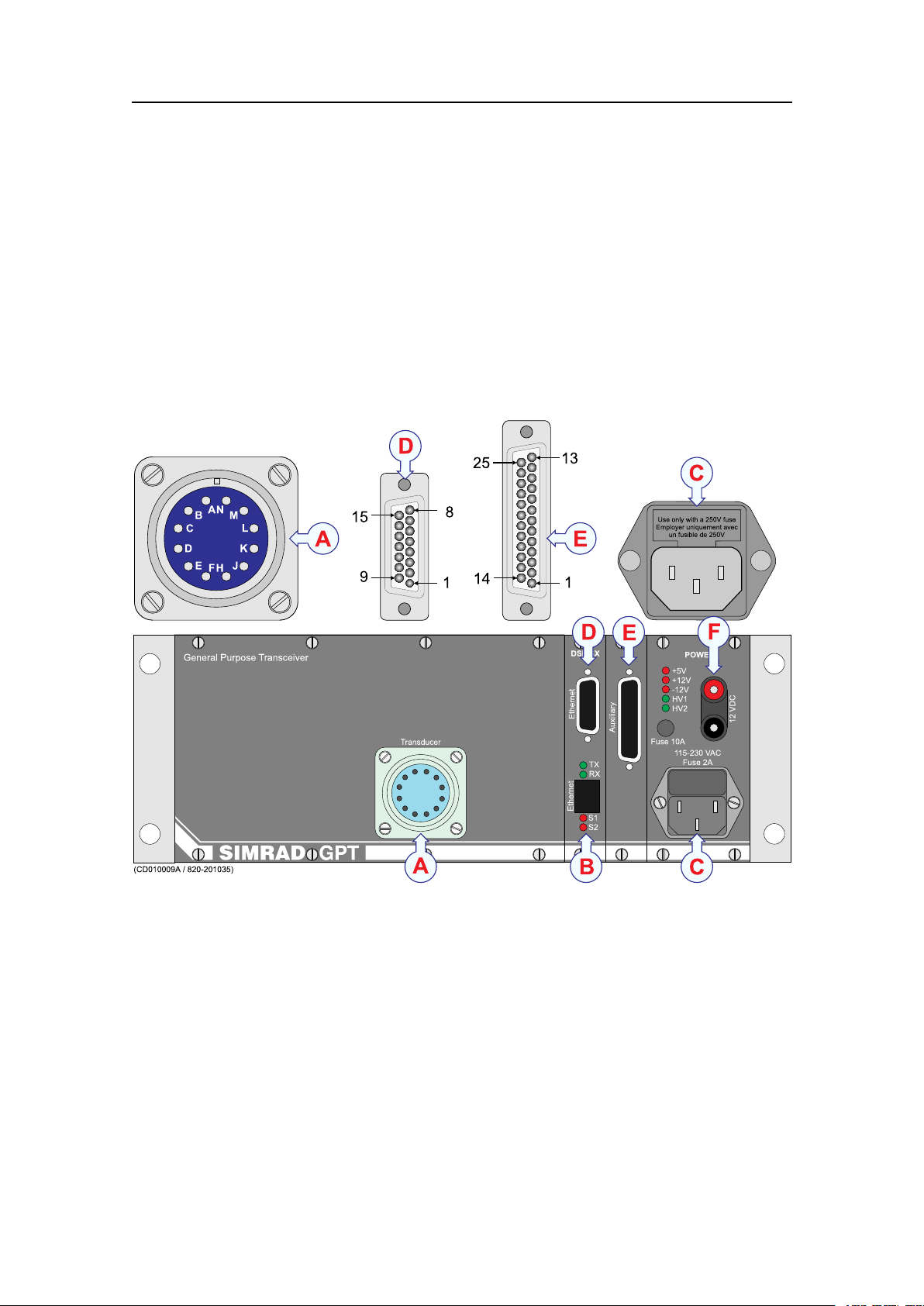
Connectoridentications
Thissectionprovidesthenecessaryillustrationstoidentifythevariousconnectorsand
terminalboardsontheechosounderunits.
GPTconnections
TheillustrationbelowshowsthecablesocketsusedontheGeneralPurposeTransceiver
(GPT).
Figure12GPTconnections
ATransducerconnector
BEthernet(RJ45)
CACmainsconnectorwithfuse
DEthernetconnector(normallynotused)
EAuxiliaryconnector
F+12Vdcinput
343522/A
35
Page 38

SimradES70
(CD010009B)
13
12
11
10
09
08
07
06
05
04
03
02
01
TRIGIN+
TRIGOUT+
ALARMOUT
EVENT IN
LOGIN
NOT USED
+5Vdc(MAX200MA)
-12Vdc(MAX100MA)
+12Vdc(MAX100MA)
TEMP IN
HEAVEIN+
ROLL+
PITCH+
TRIGIN-
TRIGOUT-
REMOTEON/OFF
GROUND
GROUND
GROUND
GROUND
GROUND
TEMP. AGND
HEAVEIN-
ROLL-
PITCH-
25
24
23
22
21
20
19
18
17
16
15
14
Figure13GPTAuxiliaryconnector
Note
Thefollowinginputsandoutputsaren o t supportedontheES70Fishndingecho
sounder:
•Temperatureinput
•Heave,rollandpitchinputs
•Eventinput
•Loginput
•Alarmoutput
36
343522/A
Page 39

ES70Cablelayout
Transducerconnections
Transducertypes
Theechosoundercanbeusedwithalargevarietyoftransducers.Thelargetransducer
connectorontheGeneralPurposeTransceiverUnit(GPT)hasbeenpreparedtoaccept
allofthem,providedthattheappurtenantcircuitboardsarettedtotheunit.The
followingtransducertypesmaybeused:
•Singlefrequency,singlebeam(highorlowpower)
•Singlefrequency,dualbeam(wideornarrow)
•Singlefrequency,splitbeam
Transducercables
Forthemajorityofthetransducers,thecablesaresuppliedbySimrad.Theseare
normallyphysicallyfastenedtothetransducer.
Note
ThedistancebetweentheGeneralPurposeTransceiverandthetransducer(s)mustbeas
shortaspossibletoavoidinterferenceandnoise.
Alltransducercablesmustberuninsteelconduits.Cableshieldsmustbeconnected
totheplughousing.
Ifthedistancebetweenthetransducerandthetransceiverexceedsthelengthofthecable,
ajunctionboxmustbeused.Thecablebetweenthejunctionboxandthetransceivermust
thenbesuppliedbySimrad,andthismustbethesametypeasusedonthetransducer(s).
Transducercablesplicing
Ifyouneedtocutorlengthenthetransducercable,youmustspliceitcorrectly.The
cablebetweenthejunctionboxandthetransceivermustthenbesuppliedbySimrad,
andthismustbethesametypeasusedonthetransducer(s).Tosplicethecable,usea
metaljunctionboxwithEMCcableglandsandaterminalblock.Theterminalblock
mustprovidesolidfasteningofthecableendsaswellassufcientinsulationbetween
thewires.Werecommendthatthecablescreenisconnectedtothejunctionboxchassis
usingtheEMCcableglands,butifyoudothis,thejunctionboxchassism
u s t n o t be
connectedtovessel’sground.
Note
D o n o t solderthewirestogetherwithonlyelectricaltapeforinsulation.Thiswillresult
inelectricalnoiseandreducedoperationalperformance.
o n o t connectthecablescreentothevessel’ sground.
D
Transducerconnectiondrawings
•Singlebeam/normalpowertransduceronpage64
343522/A
37
Page 40

SimradES70
•Singlebeam/highpowertransduceronpage65
•Dualbeam(wideornarrow)transduceronpage66
•Splitbeamtransduceronpage67
•Splitbeamtransducertosinglebeamtransceiveronpage68
•Dualfrequency,singlebeamtransduceronpage69
•ES38–10transduceronpage70
•Singlebeamtransducertosplitbeamtransceiveronpage71
•12-16/60transduceronpage72
•Deepwater,splitbeamtransduceronpage73
•50/200CombiCtransduceronpage74
•38/200CombiCtransduceronpage75
38
343522/A
Page 41

ES70Cablelayout
GPTconnector
Ensurethatthetransducerconnectoriswiredcorrectlyregardinginnerandouterscreen.
Figure14Transducerconnector
343522/A
39
Page 42

SimradES70
Cabledrawings
Thischapterprovidesdetailscabledrawingsofferingcablespecicationsandtermination
information.
Cablespecicationdrawings
•GenericRS-232Seriallineonpage41
•GenericRS-232Seriallineonpage42
•RS-232asexternaltriggeronpage43
•Sonarsynchronisationonpage44
•Commercialpowersupplyonpage45
•V esselgroundonpage46
•GPTexternalpoweronpage47
•ACmains(IEC60320)onpage48
•RJ45Ethernet,straightonpage49
•RJ45Ethernet,crossoveronpage50
•VGA/SVGADisplayonpage51
•USBonpage52
•Parallelprinteronpage53
•DVI–IDisplayonpage54
•Seriallineadapteronpage55
•GPTremoteon/offonpage56
•GPTtrigger/synchronisationon
page58
•GPTbatteryonpage59
•ITIseriallineonpage60
•PI44/54seriallineonpage61
•PI30/32seriallineonpage62
•Sonarseriallineonpage63
•Singlebeam/normalpowertransducer
onpage64
•Singlebeam/highpowertransduceron
page65
•Dualbeam(wideornarrow)transducer
onpage66
•Splitbeamtransduceronpage67
•Splitbeamtransducertosinglebeam
transceiveronpage68
•Dualfrequency,singlebeamtransducer
onpage69
•ES38–10transduceronpage70
•Singlebeamtransducertosplitbeam
transceiveronpage71
•12-16/60transduceronpage72
•Deepwater,splitbeamtransduceron
page73
•50/200CombiCtransduceronpage74
•38/200CombiCtransduceronpage75
40
343522/A
Page 43

ES70Cablelayout
GenericRS-232Serialline
Thiscableholdsamultipurposeserialline.Itprovidesinterfacewithanyperipheral
unit.Oneendofthecableconnectstothelocalunit(DTE)witha9-pinD-connector,
whiletheotherconnectstotheperipheral(DCE)asdescribedintheperipheralunit’s
documentation.Notethatthiscabledoesnotsupportallthesignalsinthestandard
RS-232specication.
Cablespecications
•Conductors:2x2x0.5mm²
•Screen:Screenedtwistedpairsandoverallbraided
•V oltage:60V
•Maximumdiameter:Limitedbytheplugs
343522/A
41
Page 44

SimradES70
GenericRS-232Serialline
Thiscablecomprisesamultipurposeserialline.Itprovidesinterfacewithanyperipheral
unit.Oneendofthecableconnectstothelocalunit(DTE)witha9-pinD-connector,
whiletheotherconnectstotheperipheral(DCE)asdescribedintheperipheralunit’s
documentation.
Inmanycases,onlytheRxD,TxTandGNDpinsareused.Twistedpairsaresufcient
inthecable.
Cablespecications
•Conductors:5x2x0.5mm²
•Screen:Screenedtwistedpairsandoverallbraided
•V oltage:60V
•Maximumdiameter:Limitedbytheplugs
42
343522/A
Page 45

ES70Cablelayout
W126
Rev.C
RS-232seriallineappliedasexternaltrigger
7
7
8
8
5
5
GroundGround
RTSRTS
CTSCTS
View
Local
9-pin ‘D’connector
Remote"Master"
9-pin'D'connector
9 6
Female9-pin
D-pinconnector
1
5
Male9-pin
D-pinconnector
5
1
6 9
RS-232asexternaltrigger
ThiscablecomprisesanRS-232seriallineappliedasanexternaltrigger.Itprovides
interfacewithanyperipheralunitthatrequirestransmit/receivesynchronization.One
endofthecableconnectstothelocalunitwitha9-pinD-connector,whiletheother
connectstotheperipheralsystemasdescribedintheperipheralunitdocumentation.
Cablespecications
•Conductors:9x2x0.5mm²
•Screen:Screenedtwistedpairsandoverallbraided
•V oltage:60V
•Maximumdiameter:Limitedbytheplugs
343522/A
43
Page 46

SimradES70
Sonarsynchronisation
ThiscableconnectstheechosoundertotheInterfaceUnitonaSimradsonar.Thecable
allowsforexternalsynchronisationofthesonartransmission.
Cablespecications
•Conductors:4x0.5mm²
•Screen:Overallbraided
•Voltage:60V
•Maximumdiameter:Denedbytheplugs
44
343522/A
Page 47

ES70Cablelayout
W300
Rev.B
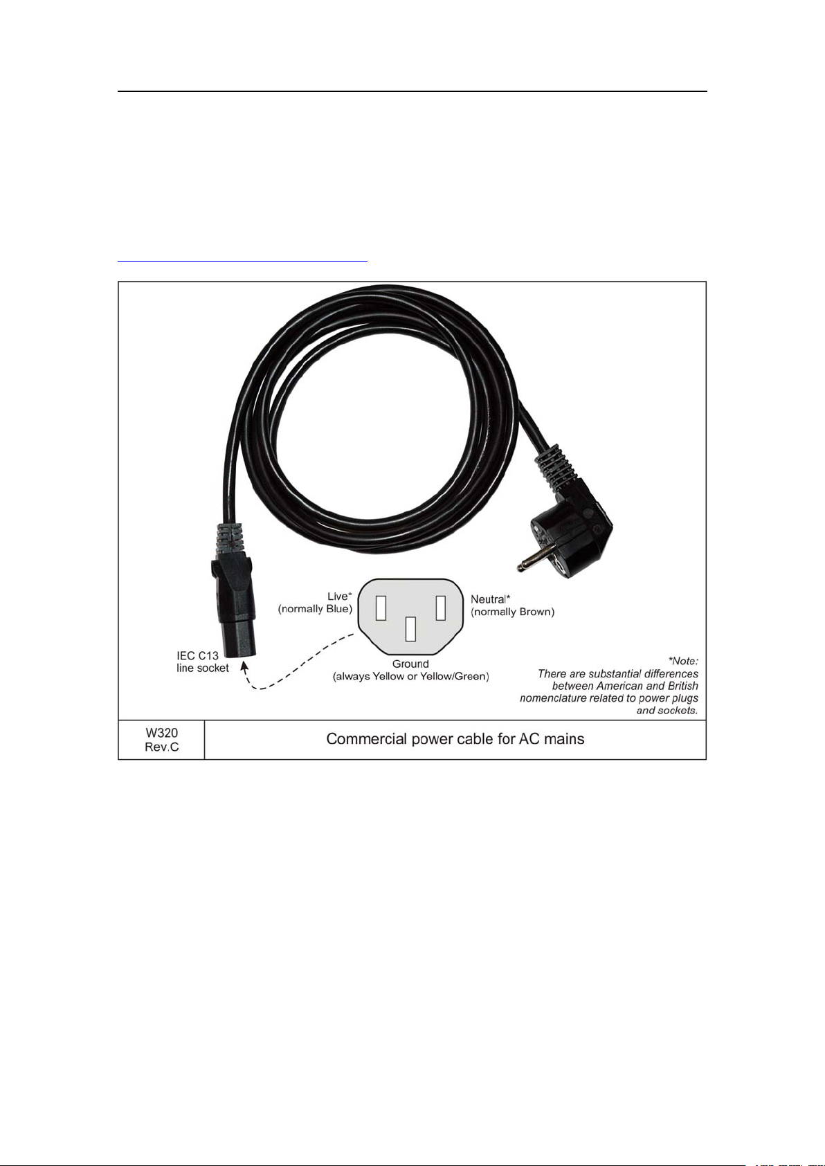
Commercialpowersupply
Thepowersupplyisfittedwithplug
tosuitthenationalstandard.
(Britishstandardshownasexampleonly .)
PlugtypeandelectricalpropertiesonDCoutput
aresettofitthedevicetobepowered.
Commercialpowersupply
Thisisastandardcommercialpowersupply.Theinputisnormally115and/or230
Vac,whiletheoutputvoltageandpowercapacityissetuptomatchthedeviceitshall
beusedwith.Alargevarietyofthesepowersuppliesexist.Somewillalsohavean
in-linepower“box”.ThesetypeswillhaveanACpowercableononeside,andtheDC
outputsupplycableontheother.
Cablespecications
•Notapplicable
343522/A
45
Page 48

SimradES70
Vesselground
Thiscableisusedtoconnectasystemunittotheship’sground.Notethatthiscablemust
beasshortaspossible.
Cablespecications
•Conductors:1x6mm²
•Screen:None
•Voltage:60V
•Maximumdiameter:N/A
46
343522/A
Page 49

ES70Cablelayout
W319
Rev.A
ExternalpowersupplyforGeneralPurpose Transceiver
SIMRAD
GPT
230Vacinput
+13.2Vdcoutput
GPTexternalpower
Inordertosuppresselectricnoise,certainechosoundercongurationsrequireanexternal
powersupply.Thispowersupplyisthenusedinsteadofthe230Vacpowercable.
Note
Theexternalpowersupplyisnotrequiredfortransceiversoperatingon115V ac.
343522/A
47
Page 50
SimradES70
ACmains(IEC60320)
Thisisacommercial230V acpowercableformainspower.Oneendistted
withanIECplug,theotherwithastandardEuropeanmainsplug.Thisisa
standardcabletypesuppliedindifferentlengths.Foradditionaldetails,see
t t p : / / e n . w i k i p e d i a . o r g / w i k i / I E C _ 3 2 0 .
h
Cablespecications
•Conductors:2x1.5mm²+GND
•Screen:None
•Voltage:750V
•Maximumdiameter:Setbytheplugs
48
343522/A
Page 51

ES70Cablelayout
RJ45Ethernet,straight
ThiscableisusedtoprovidestandardEthernetconnections.Notethatvariouscategories
exists.Normally,CAT -5EandCAT -6cablesareusedinlocalareanetworkswith
bandwidthexceeding100Mbit.Ethernetcablesareavailablecommerciallyindifferent
lengths,coloursandcategories.
Inordertopreventnoiseandcrosstalk,youarestronglyadvisedtousethecablepairs
indicatedinthedrawing.
Cablespecications
•Notapplicable.Thisisacommercialcable.
Moreinformation
t t p : / / e n . w i k i p e d i a . o r g
•h
343522/A
49
Page 52

SimradES70
W405
Rev.A
Pairs
1 1
TxData+ TxData+
RxData- RxData-
RxData+ RxData+
TxData- TxData-
3 3
2 2
4 4
5 5
7 7
6 6
8 8
RJ45plug
Ethernet10Base-T “Crossover ”
(White/Orange)
(Orange)
(White/Green)
(Blue)
(White/Blue)
(Green)
(White/Brown)
(Brown)
Pin8
Pin8
View
Pin1
Pin1
Endview
ofRJ45plug
RJ45Ethernet,crossover
Thiscableisusedtoprovidestandardethernetconnections.Notethatvariouscategories
exists.Normally,Cat.5andCat.6cablesareusedinlocalareanetworkswithbandwidth
exceeding100Mbit
Ethernetcablesareavailablecommerciallyindifferentlengths,coloursandcategories.
Inordertopreventnoiseandcrosstalk,youarestronglyadvisedtousethecablepairs
indicatedinthedrawing.
Cablespecications
•Notapplicable.Thisisacommercialcable.
Moreinformation
t t p : / / e n . w i k i p e d i a . o r g
•h
50
343522/A
Page 53

ES70Cablelayout
VGA/SVGADisplay
ThisisastandardVGAandSVGAvideocable.Oneendisnormallyconnectedtothe
display,whiletheotherendisterminatedinastandardD-connector.
Cablespecications
•Notapplicable.Thisisacommercialcable.
343522/A
51
Page 54

SimradES70
USB
JustaboutanycomputerthatyoubuytodaycomeswithoneormoreUniversalSerial
Bus(USB)connectorsontheback.Theseconnectorsletyouattacheverythingfrom
mousetoprinterstoyourcomputerquicklyandeasily.Sincetheoperatingsystem
supportsUSB,installationofdevicedriversisalsoeasy.Inmostcases,theUSBcableis
commercial,andtheyarenormallysuppliedwiththeexternaldevices,However,USB
cablesarealsoavailablecommerciallyindifferentxedlengths.Formoreinformation,
seealsoh
t t p : / / e n . w i k i p e d i a . o r g .
Cablespecications
•Notapplicable.Thisisacommercialcable.
52
343522/A
Page 55

ES70Cablelayout
Parallelportconnector
(IEEE1284-A)
25-pinD-connector
25
14
1
13
Thesocketontherear
sideofthecomputer
isnormallya25-pinfemale
D-connector .
W505
Rev.E
Centronicsparallelprintercable
1
3
2
4
5
7
6
8
9
11
10
15
18-24
Strobe
Data0
Data1
Data2
Data3
Data4
Data5
Data6
Data7
Acknowledge
Busy
Error
Ground
Parallelprinter
Thisisastandard“Centronics”parallelprintercable.Itisprovidedready-madewith
printers,andalsoobtainablefromcommercialretailers.
Terminationismadewith25–pin“D-sub”connectorinoneend,parallelportconnector
intheotherend(IEEE1284–A)
Cablespecications
•Notapplicable.Thisisacommercialcable.
343522/A
53
Page 56

SimradES70
DVI–IDisplay
ThiscableisastandardDVI-Icable.Itisnormallyprovidedwiththecolourdisplay.
FormoreinformationabouttheDVIsignals,seeh
PinSignalPinSignal
1
TMDSData2-(Digitalred-(Link1))
2
TMDSData2+(Digitalred+(Link1))
3
TMDSData2/4shield
4
TMDSData4-(Digitalgreen-(Link2))
5
TMDSData4+(Digitalgreen+(Link2))
6
DDCclock
7
DDCdata
8
Analogverticalsync
9
TMDSData1-(Digitalgreen-(Link1))
10
TMDSData1+(Digitalgreen+(Link1))
11
TMDSData1/3shield
12
TMDSData3-(Digitalblue-(Link2))
13
TMDSData3+(Digitalblue+(Link2))
14
+5Vdc(Powerformonitorwhenin
standby)
TMDS=TransitionMinimizedDifferential
Signaling
15
16
17
18
19
20
21
22
23
24
C1
C2
C3
C4
C5
t t p : / / e n . w i k i p e d i a . o r g .
Ground(Returnforpin14andanalogsync)
Hotplugdetect
TMDSdata0-(Digitalblue-(Link1)and
digitalsync)
TMDSdata0+(Digitalblue+(Link1)and
digitalsync)
TMDSdata0/5shield
TMDSdata5-(Digitalred-(Link2))
TMDSdata5+(Digitalred+(Link2))
TMDSclockshield
TMDSclock+(Digitalclock+(Links1
and2))
TMDSclock-(Digitalclock-(Links1and
2))
Analogred
Analoggreen
Analogblue
Analoghorizontalsync
Analogground(ReturnforR,GandB
signals)
54
343522/A
Page 57

ES70Cablelayout
W510
Rev.A
Seriallineadapter
Tosocket
oncomputer
Female9-pin
D-connectors
identifiedas"A"
through"D"
Seriallineadapter
Thisisacommercialadapter.ItallowsyoutoconnectfourRS-232seriallinestoa
commonsocketonthecomputer.
Cablespecications
•Notapplicable
343522/A
55
Page 58

SimradES70
Resetand
Remoteon/of f
W620A
Rev.E
Remoteon/of f
22
22
23
23
Thecablescreenisconnectedtotheplughouse.
Thecablescreenisconnectedtotheplughouse.
SIMRAD GPT
GPT
25-pinD-subconnector
"Remote"connector
ondisplay
25
14
1
13
Auxiliary
connector
(female)
GPTremoteon/off
Thiscableisusedtoconnectaremoteon/offswitchtotheGeneralPurposeTransceiver
(GPT).Theswitchcanbelocatedinaseparateboxmanufacturedbytheinstallation
shipyard,orincorporatedonacommonswitchpanel.
Remotepoweron/offwhenasingletransceiverisused
Cablespecications
•Conductors:2x0.22mm²
•Screen:Overallbraided
•V oltage:60V
•Maximumdiameter:Denedbytheplugs
56
343522/A
Page 59

ES70Cablelayout
W620A1
Rev.A
Remoteon/of fwithmultipeGPT sandasingleswitch
22
23
22
23
22
23
22
23
22
23
GPTNo.1 GPTNo.2
Auxiliaryconnectors
ontheindividual
transceivers
Topsideswitchbox
Connectionbox
Two-wirecablefromtransceiverroomtotopsideequipment
GPTNo.3 GPTNo.4 GPTNo.5
A
B
W620A2
Rev.A
Remoteon/of fwithmultipeGPT sandaseparateswitches
22
23
22
23
22
23
22
23
22
23
GPTNo.1 GPTNo.2
Auxiliaryconnectors
ontheindividual
transceivers
Topsideswitchbox
Connectionbox
Cablefromtransceiverroomtotopsideequipment
GPTNo.3 GPTNo.4 GPTNo.5
A1
A2
A3
A4
A5
B
Remotepoweron/offwhenmultipletransceiversareused
Whenmultipletransceiversareused,twowiringoptionsareavailable:
•Youcanswitchalltransceiversoffandonsimultaneouslyusingasingleswitch.
•Youcanuseoneswitchforeachtransceiverandswitchpoweronandoffindividually.
Bothoptionsareillustratedbelowusingvetransceiversasanexample.
Figure15Singleswitch
Figure16Individualswitches
343522/A
57
Page 60

SimradES70
25
GPT
25-pinD-subconnector
24
13
12
TrigOut(+)
TrigOut(-)
TrigIn(+)
TrigIn(-)
SIMRAD GPT
25
14
1
13
Auxiliary
connector
(female)
Thecablescreenisconnectedtotheplughouse.
W620B
Rev.D
Synchronisation/Externaltrigger
GPTtrigger/synchronisation
ThiscableisusedtoconnecttheGeneralPurposeTransceiver(GPT)toanexternal
systemforsynchronisationpurposes.Itconnectstothe25–pinD-subconnectoron
thefrontsideoftheGPT.
Cablespecications
•Conductors:2x2x0.22mm²
•Screen:Braidedpairsandoverallbraided
•V oltage:60V
•Maximumdiameter:Denedbytheplugs
58
343522/A
Page 61

ES70Cablelayout
Bananaplugs
andsockets
Battery
+
W620E
Rev.A
GPT Battery
GPTbattery
ThiscableisusedtoconnectabatterytotheGeneralPurposeTransceiver(GPT).Red
plugandredsocketisnormallyusedforpositive(+).Blackplugandblacksocketis
normallyusedfornegative(-).
Cablespecications
•Conductors:2x1.5mm²
•Screen:N/A
•V oltage:Selecttotbatteryvoltage
•Maximumdiameter:N/A
343522/A
59
Page 62

SimradES70
ITIserialline
Thiscableisusedtoprovideatwo-waycommunicationtoaSimradITITrawlsystem.
Cablespecications
•Conductors:9x2x0.5mm²
•Screen:Screenedtwistedpairsandoverallbraided
•Voltage:60V
•Maximumdiameter:Limitedbytheplugs
60
343522/A
Page 63

ES70Cablelayout
PI44/54serialline
Thiscableisusedtoprovideatwo-waycommunicationtoaSimradPI44orPI54catch
monitoringsystem.
Cablespecications
•Conductors:9x2x0.5mm²
•Screen:Screenedtwistedpairsandoverallbraided
•Voltage:60V
•Maximumdiameter:Limitedbytheplugs
343522/A
61
Page 64

SimradES70
PI30/32serialline
Thiscableisusedtoprovideatwo-waycommunicationtoaSimradPI30orPI32catch
monitoringsystem.
Cablespecications
•Conductors:9x2x0.5mm²
•Screen:Screenedtwistedpairsandoverallbraided
•Voltage:60V
•Maximumdiameter:Limitedbytheplugs
62
343522/A
Page 65
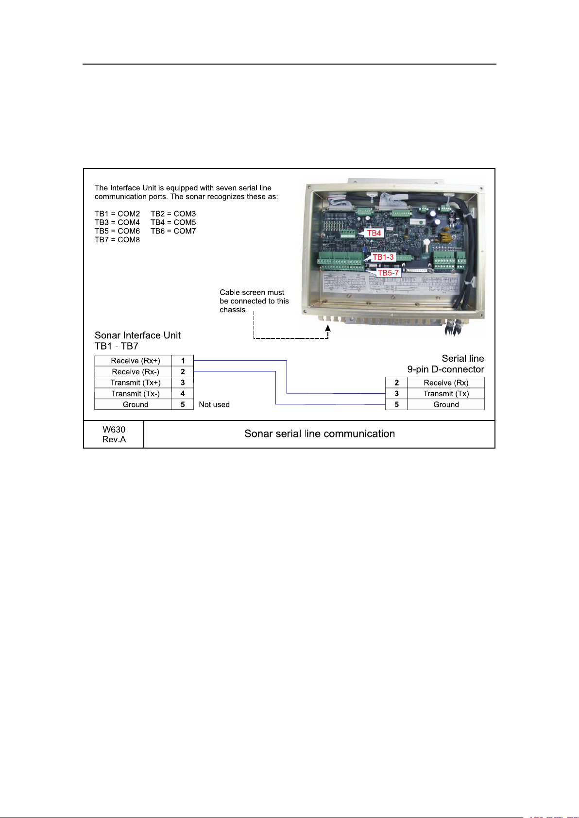
ES70Cablelayout
Sonarserialline
Thiscableisusedtoprovideatwo-waycommunicationtoasonarsystemusingan
InterfaceUnit.
Cablespecications
•Conductors:9x2x0.5mm²
•Screen:Screenedtwistedpairsandoverallbraided
•Voltage:60V
•Maximumdiameter:Limitedbytheplugs
343522/A
63
Page 66

SimradES70
M
E
F
J
H
D
C
K
L
A
B
N
Transducer
cable
D
C
JunctionBox(1:1)
(Optional)
GPT Transducer
socket
Screen
Drainwire
Connecttoplughousing
W802-1
Rev.E
Singlefrequency ,singlebeam,normalpowertermination
Singlebeam/normalpowertransducer
Thisistheterminationofthetransducercablefromasinglefrequency,singlebeam
transducertothetransducersocketontheGeneralPurposeTransceiverUnit(GPT).The
otherendofthecableispermanentlyxedtothetransducer.
Ifyouneedtosplicethetransducercable,itisveryimportanttousethecorrectcable,
andtoavoidgroundloops.W estronglyrecommendtheuseofajunctionbox.Wealso
recommendthatyouinstallthetransducercableinasteelconduit.
Formoreinformation,see:
•Transducercablesplicingonpage142
•Steelconduitonpage142
•GPTTransducerplugconnectiononpage107
64
343522/A
Page 67
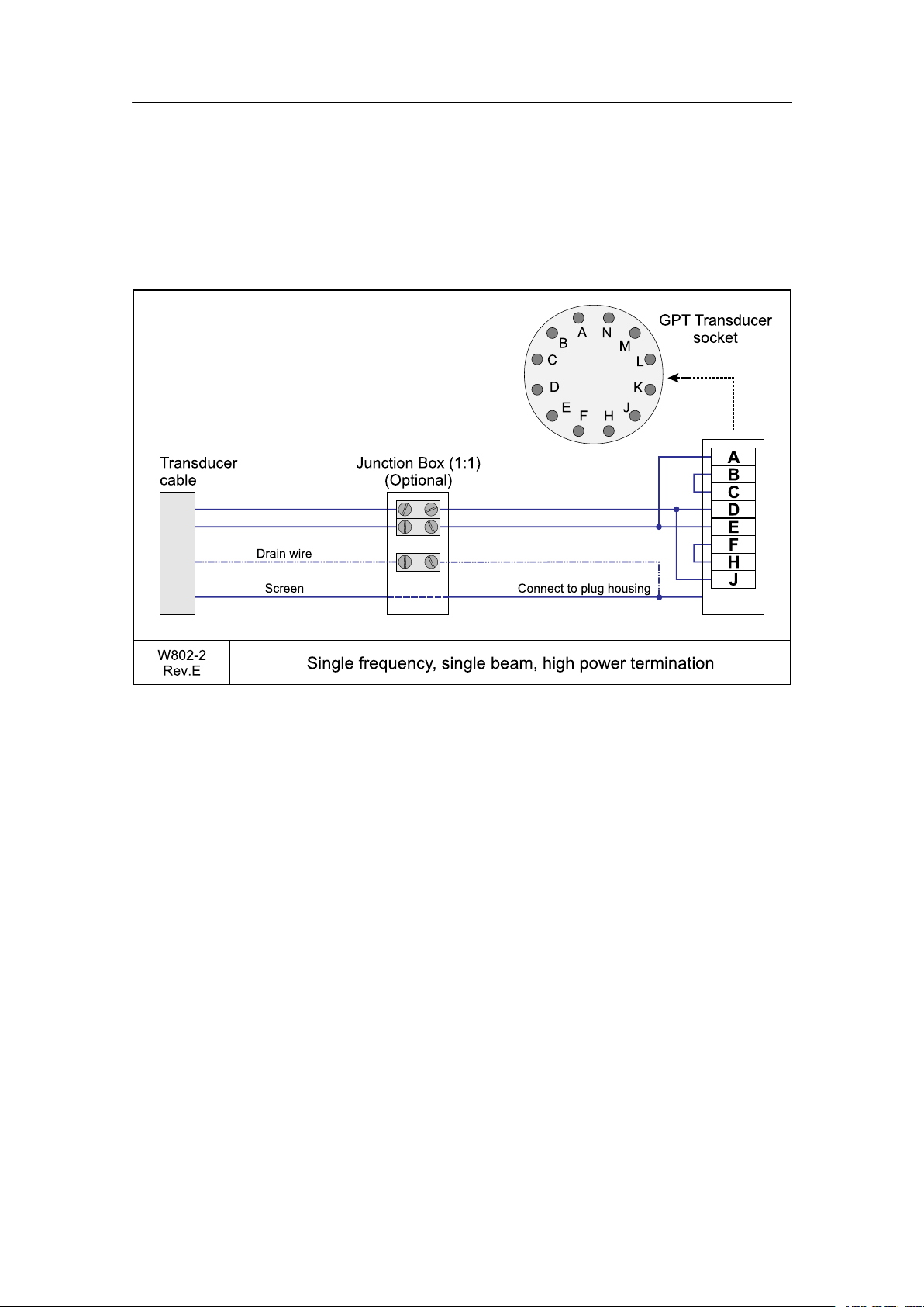
ES70Cablelayout
M
E
F
J
H
D
C
K
L
A
B
N
Transducer
cable
E
A
B
C
D
H
J
F
JunctionBox(1:1)
(Optional)
GPT Transducer
socket
Screen Connecttoplughousing
W802-2
Rev.E
Singlefrequency ,singlebeam,highpowertermination
Drainwire
Singlebeam/highpowertransducer
Thisistheterminationofthetransducercablefromasinglefrequency,singlebeam
transducertothetransducersocketontheGeneralPurposeTransceiverUnit(GPT).The
otherendofthecableispermanentlyxedtothetransducer.
Ifyouneedtosplicethetransducercable,itisveryimportanttousethecorrectcable,
andtoavoidgroundloops.W estronglyrecommendtheuseofajunctionbox.Wealso
recommendthatyouinstallthetransducercableinasteelconduit.
Formoreinformation,see:
•Transducercablesplicingonpage142
•Steelconduitonpage142
•GPTTransducerplugconnectiononpage107
343522/A
65
Page 68

SimradES70
M
E
F
J
H
D
C
K
L
A
B
N
Transducercable
Narrow
Transducercable
Wide
JunctionBox(1:1)
(Optional)
JunctionBox(1:1)
(Optional)
GPT Transducer
socket
W802-3
Rev.E
Singlefrequency ,dualbeam(wideornarrow)termination
D
C
Screen Connecttoplughousing
Screen
Yellow/Green
Blue
Brown
Blue
Black
Connecttoplughousing
D
C
Dualbeam(wideornarrow)transducer
Thisistheterminationofthetransducercablefromasinglefrequency,dualbeam
transducertothetransducersocketontheGeneralPurposeTransceiverUnit(GPT).The
otherendofthecableispermanentlyxedtothetransducer.
Note
Alwayscheckthetransmitpowerifwidebeamisselectedinordernottoexceedthe
powercapacityonthetransducer.
Ifyouneedtosplicethetransducercable,itisveryimportanttousethecorrectcable,
andtoavoidgroundloops.W estronglyrecommendtheuseofajunctionbox.Wealso
recommendthatyouinstallthetransducercableinasteelconduit.
Formoreinformation,see:
•Transducercablesplicingonpage142
•Steelconduitonpage142
•GPTTransducerplugconnectiononpage107
66
343522/A
Page 69

ES70Cablelayout
M
E
F
J
H
D
C
K
L
A
B
N
Transducer
cable
E
H
D
C
F
J
A
B
JunctionBox(1:1)
(Optional)
GPT Transducer
socket
Channel1
Channel2
Channel3
Channel4
Connecttoplughousing
W802-4
Rev.E
Singlefrequency ,splitbeamtermination
Forward
Starboard
Port
Sectionsseenfromtop
ofthetransducer
2
1
3
4
2 1
3
4
White
Blue
White
Blue
Blue
Orange
Green
Brown
White
White
White
White
White
Blue
White
Blue
Black
Black
Black
Black
Black
Black
Black
Black
Screen
Alternativecable
colours
Splitbeamtransducer
Thisistheterminationofthetransducercablefromasinglefrequency,splitbeam
transducertothetransducersocketontheGeneralPurposeTransceiverUnit(GPT).The
otherendofthecableispermanentlyxedtothetransducer.
Ifyouneedtosplicethetransducercable,itisveryimportanttousethecorrectcable,
andtoavoidgroundloops.W estronglyrecommendtheuseofajunctionbox.Wealso
recommendthatyouinstallthetransducercableinasteelconduit.
Formoreinformation,see:
•Transducercablesplicingonpage142
•Steelconduitonpage142
•GPTTransducerplugconnectiononpage107
343522/A
67
Page 70

SimradES70
M
E
F
J
H
D
C
K
L
A
B
N
Transducer
cable
C
D
JunctionBox(1:1)
(Optional)
GPT Transducer
socket
Connecttoplughousing
W802-5
Rev.E
Singlefrequency ,splitbeamconnectedassinglebeam
Forward
Starboard
Port
Sectionsseenfromtop
ofthetransducer
2
1
3
4
2 1
3
4
White
Blue
White
Blue
Blue
Orange
Green
Brown
White
White
White
White
White
Blue
White
Blue
Black
Black
Black
Black
Black
Black
Black
Black
Screen
Alternativecable
colours
Splitbeamtransducertosinglebeamtransceiver
Thisistheterminationofthetransducercablefromasinglefrequency,splitbeam
transducer-wiredasasinglebeamtransducer-tothesocketontheGeneralPurpose
TransceiverUnit(GPT).Theotherendofthecableispermanentlyxedtothetransducer.
Ifyouneedtosplicethetransducercable,itisveryimportanttousethecorrectcable,
andtoavoidgroundloops.W estronglyrecommendtheuseofajunctionbox.Wealso
recommendthatyouinstallthetransducercableinasteelconduit.
Formoreinformation,see:
•Transducercablesplicingonpage142
•Steelconduitonpage142
•GPTTransducerplugconnectiononpage107
68
343522/A
Page 71

ES70Cablelayout
M
E
F
J
H
D
C
K
L
A
B
N
Transducer
cable
JunctionBox(1:1)
(Optional)
GPT Transducer
socket
W802-6
Rev.E
Dualfrequency ,singlebeamtermination
J
D
H
C
Screen
Black
Black
Black
Black
White
White
White
White
Connecttoplughousing
4
17
"Auxiliary"25-pin
D-connectoronGPT
Thermistor
Thermistor
Notused
Lowfrequency
Lowfrequency
Highfrequency
Highfrequency
Pair1
Pair2
Pair3
Pair4
Dualfrequency ,singlebeamtransducer
Thisistheterminationofthetransducercablefromadualfrequency,singlebeam
transducertothesocketontheGeneralPurposeTransceiverUnit(GPT).Theotherend
ofthecableispermanentlyxedtothetransducer.
Ifyouneedtosplicethetransducercable,itisveryimportanttousethecorrectcable,
andtoavoidgroundloops.W estronglyrecommendtheuseofajunctionbox.Wealso
recommendthatyouinstallthetransducercableinasteelconduit.
Formoreinformation,see:
•Transducercablesplicingonpage142
•Steelconduitonpage142
•GPTTransducerplugconnectiononpage107
343522/A
69
Page 72

SimradES70
M
E
F
J
H
D
C
K
L
A
B
N
ES38-10
transducercable
J
E
F
H
D
C
JunctionBox(1:1)
(Optional)
GPT Transducer
socket
White
White
White
Black
Black
Black
Screen Connecttoplughousing
W802-8
Rev.A
ES38-10 Transducercabletermination
FWD
Sectionsseenfromtop
ofthetransducer
1
2
3
1
2
3
ES38–10transducer
ThisistheterminationofthetransducercablefromtheES38–10split-beamtransducerto
thetransducersocketontheES60andEK60GeneralPurposeTransceiverUnit(GPT).
Theotherendofthecableispermanentlyxedtothetransducer.
Therearefourpairsinthetransducercable,eachwithoneblackandonewhitecable.
Eachpairismarkedwithasmalllabelidentifyingthetransducersection.Pairnumber
4isnotused.
Ifyouneedtosplicethetransducercable,itisveryimportanttousethecorrectcable,
andtoavoidgroundloops.W estronglyrecommendtheuseofajunctionbox.Wealso
recommendthatyouinstallthetransducercableinasteelconduit.
Formoreinformation,see:
•Transducercablesplicingonpage142
•Steelconduitonpage142
•GPTTransducerplugconnectiononpage107
70
343522/A
Page 73

ES70Cablelayout
M
E
F
J
H
D
C
K
L
A
B
N
Transducer
cable
E
A
B
C
D
H
J
F
JunctionBox(1:1)
(Optional)
GPT Transducer
socket
Screen Connecttoplughousing
W802-9
Rev.A
Singlefrequency ,singlebeam,tosplitbeamtransceiver ,termination
Singlebeamtransducertosplitbeamtransceiver
Thisistheterminationofthetransducercablefromasinglefrequency,singlebeam
transducertothesocketonasplitbeamGeneralPurposeTransceiverUnit(GPT).The
otherendofthecableispermanentlyxedtothetransducer.
Ifyouneedtosplicethetransducercable,itisveryimportanttousethecorrectcable,
andtoavoidgroundloops.W estronglyrecommendtheuseofajunctionbox.Wealso
recommendthatyouinstallthetransducercableinasteelconduit.
Formoreinformation,see:
•Transducercablesplicingonpage142
•Steelconduitonpage142
•GPTTransducerplugconnectiononpage107
343522/A
71
Page 74

SimradES70
M
E
F
J
H
D
C
K
L
A
B
N
GPT Transducer
socket
W802-10
Rev.A
12-16/60 Transducercabletermination
Transducer
cable
JunctionBox(1:1)
(Optional)
Brown
Yellow
Blue
Black
Screen Connecttoplughousing
Transducer
cable
ConfigurationWIDE
ConfigurationNARROW
C
D
JunctionBox(1:1)
(Optional)
Brown
Yellow
Blue
Black
Screen Connecttoplughousing
C
D
12-16/60transducer
Thisistheterminationofthetransducercablefromthe12–16/60singleordualbeam
transducertothetransducersocketontheGeneralPurposeTransceiverUnit(GPT).The
otherendofthecableispermanentlyxedtothetransducer.
Note
Alwayscheckthetransmitpowerifwidebeamisselectedinordernottoexceedthe
powercapacityonthetransducer.
Ifyouneedtosplicethetransducercable,itisveryimportanttousethecorrectcable,
andtoavoidgroundloops.W estronglyrecommendtheuseofajunctionbox.Wealso
recommendthatyouinstallthetransducercableinasteelconduit.
Formoreinformation,see:
•Transducercablesplicingonpage142
•Steelconduitonpage142
•GPTTransducerplugconnectiononpage107
72
343522/A
Page 75

ES70Cablelayout
M
E
F
J
H
D
C
K
L
A
B
N
Burton
connector
E
H
D
C
F
J
A
B
Connectionbox
withBurtonsocket
GPT Transducer
socket
Quadrant1
Quadrant2
Quadrant3
Quadrant4
Screentoplughousing
W802-11
Rev.A
Deepwatertransducer ,termination
Forward
Starboard
Port
Quadrantsseenfromtop
ofthetransducer
2 1
3
4
2
1
6
3
5
4
7
8
2
1
6
3
5
4
7
8
Aftstarboard
Forestarboard
Foreport
Aftport
Pin1
Q1
Q2
Q3
Q4
Pin7
Pin3
Pin2
+
+
+
+
-
-
-
-
Pin4
Pin8
Pin6
Pin5
3 2 1
6 5 4
8 7
Deepwater ,splitbeamtransducer
Thisistheterminationofthetransducercablefromadeepwatertransducer.This
transducerisdesignedtobeusedtowedbodies.Thecableisequippedwithawatertight
connector.Theotherendofthecableispermanentlyxedtothetransducer.
Ifyouneedtosplicethetransducercable,itisveryimportanttousethecorrectcable,
andtoavoidgroundloops.W estronglyrecommendtheuseofajunctionbox.Wealso
recommendthatyouinstallthetransducercableinasteelconduit.
Formoreinformation,see:
•Transducercablesplicingonpage142
•Steelconduitonpage142
•GPTTransducerplugconnectiononpage107
343522/A
73
Page 76

SimradES70
M
E
F
J
H
D
C
K
L
A
B
N
Mini-Con-X
connector
"Mini-Con-X"providedbywww .conxall.com
Note: Thetransducercablemustnotbeexposed
tooilorotherpetroleumfluids.
H
C
J
D
4
17
Connectionbox
withMini-Con-Xsocket
"Auxiliary"25-pin
D-connectoronGPT
GPT Transducer
socket
Screentoplughousing
W802-12
Rev.B
50/200CombiCtransducer ,termination
3
3
1
1
6
6
5
5
4
4
2
2
7
7
50kHz
50kHz
50kHz
50kHz
200kHz
200kHz
200kHz
200kHz
Thermistor
Thermistor
Thermistor
Thermistor
Red
Black
Blue
White
Green
Yellow
Screen
3
1
6
5
4
2
7
A
smallcircularmarkeridentifiespin1.
(1)
(2)
(3)
(6)
(7)
(4)
(5)
View:Looking thesocketontherearsideofthecabinetinto
50/200CombiCtransducer
ThisistheterminationofthetransducercablefromtheSimrad50/200CombiCtransducer.
ThetransducercableisterminatedinaMini-Con-XconnectormanufacturedbyConxall
w w . c o n x a l l . c o m ).Theotherendofthecableispermanentlyxedtothetransducer.
(w
Ifyouneedtosplicethetransducercable,itisveryimportanttousethecorrectcable,
andtoavoidgroundloops.W estronglyrecommendtheuseofajunctionbox.Wealso
recommendthatyouinstallthetransducercableinasteelconduit.
Formoreinformation,see:
•Transducercablesplicingonpage142
•Steelconduitonpage142
•GPTTransducerplugconnectiononpage107
74
343522/A
Page 77

ES70Cablelayout
M
E
F
J
H
D
C
K
L
A
B
N
Mini-Con-X
connector
"Mini-Con-X"providedbywww .conxall.com
Note: Thetransducercablemustnotbeexposed
tooilorotherpetroleumfluids.
C
H
D
J
4
17
Connectionbox
withMini-Con-Xsocket
"Auxiliary"25-pin
D-connectoronGPT
GPT Transducer
socket
Screentoplughousing
W802-13
Rev.A
38/200CombiCtransducer ,termination
3
3
1
1
6
6
5
5
4
4
2
2
7
7
200kHz
200kHz
200kHz
200kHz
38kHz
38kHz
38kHz
38kHz
Thermistor
Thermistor
Thermistor
Thermistor
Red
Black
Blue
White
Green
Yellow
Screen
3
1
6
5
4
2
7
A
smallcircularmarkeridentifiespin1.
(1)
(2)
(3)
(6)
(7)
(4)
(5)
View:Looking thesocketontherearsideofthecabinetinto
38/200CombiCtransducer
ThisistheterminationofthetransducercablefromtheSimrad38/200CombiCtransducer.
ThetransducercableisterminatedinaMini-Con-XconnectormanufacturedbyConxall
w w . c o n x a l l . c o m ).Theotherendofthecableispermanentlyxedtothetransducer.
(w
Ifyouneedtosplicethetransducercable,itisveryimportanttousethecorrectcable,
andtoavoidgroundloops.W estronglyrecommendtheuseofajunctionbox.Wealso
recommendthatyouinstallthetransducercableinasteelconduit.
Formoreinformation,see:
•Transducercablesplicingonpage142
•Steelconduitonpage142
•GPTTransducerplugconnectiononpage107
343522/A
75
Page 78

SimradES70
Softwareinstallation
ThischapterdescribeshowtoinstalltheES70software,howtoupgrade,howtoobtaina
softwarelicense,andnallyhowtoremovethesoftwareinstallation.
Topics
•HowtoinstalltheES70softwareonpage76
•HowtoobtaintheES70licenseonpage77
•HowtoupgradetheES70softwareonpage77
•HowtoremovetheES70softwareonpage78
HowtoinstalltheES70software
Usethisprocedureifyouneedtoinstallthesoftwareonanewcomputer.Notethat
minimumhardwareandsoftwarerequirementsmustbemetbythecomputer.
1Powerupthecomputer.
2InserttheES70CD-ROM.
3Observethattheinstallationprogramopens.
Iftheinstallationprogramdoesnotstartautomatically,usealemanagertoaccess
theCDfolder.Double-clickontheSetup.exeletostarttheinstallation.
4AllowtheES70installationtorun.Followtheinstructionsprovided.
5Oncetheinstallationhasbeencompleted,double-clicktheES70icononthedesktop
tostarttheapplication.
WhentheES70starts,youmayseeadialogrequestingpermissiontoupgradethe
rmwareonthetransceiver.Thishappensifthermwareonthetransceiverisolder
thanthermwareprovidedasapartoftheES70software.Sincefunctionality
ontheES70maydependonthermwareinthetransceiver,clickY estoupgrade
thetransceiver.
6IfyouuseWindows7operatingsystem:
aObservethatWindows7Firewallwillopenadialogrequestinginformation
aboutthenetwork.
bSelectPublic,andclickAllowaccess.
7Observethestart-upprocedureintheGettingstartedchapter.
76
343522/A
Page 79

Softwareinstallation
ThischapterisprovidedintheES70OperatormanualandES70Referencemanual.
HowtoobtaintheES70license
TheES70requiresavalidlicensetooperate.Withoutalicenseyouwillnotbeableto
communicatewiththetransceiver.
Note
Ifyoureplaceyourcomputer,orifyoureplacemajorcomponentsinsideyourcomputer ,
youwillneedanewlicensecode.
1Double-clicktheES70icononthedesktoptostarttheapplication.
2ClicktheSetupiconundertheMainmenutoopentheSetupsub-menu.
3ClickInstallationtoopentheInstallationsub-menu.
Onthesub-menu,clickSoftwareLicensetoopentheSoftwareLicensedialog.
4WritedowntheHardwareIDprovidedbytheSoftwareLicensedialog.
5Contactyourdealertoorderthesoftwarelicense.
Yourdealerwillneedthefollowinginformationfromyoutoplacetheorder:
•Vesselnameandcallsign
•Vesseltype(trawler,purseseiner,etc.)
•Vesselowner’sname,addressandcontactinformation
•Serialnumberonalltransceivers
•HardwareID
6Whenthesoftwarelicenseisreturned,starttheES70,opentheSoftwareLicense
dialog,andclickEnterLicenceString.
7Writedownthecode,andclickOk.
8ClickOKtosavethecurrentsettingsandclosethedialog.
HowtoupgradetheES70software
Usethisprocedureifyouwishtoreinstallthesoftware,orreceiveanewCD-ROM
withasoftwareupgrade.
343522/A
77
Page 80

SimradES70
1Observetheprocedureforsoftwareinstallation.
Unlessyouhavemadeanyhardwarechangesonyourcomputer,theexisting
softwarelicensewillbeused.
HowtoremovetheES70software
UsethisprocedureifyouneedtoremovealltheES70softwarefromthecomputer.Note
thatalldataintheES70directorywillbeerased.
1Observetheoperatingsystem’sfunctionalityforsoftwareremoval.
78
343522/A
Page 81

Connectingthetransceiver
Connectingthetransceiver
ThischapterexplainshowtoconnecttheES70computertothetransceiver,andhowto
setupthefrequencychannels.
Eachtransceivercontainsoneormoref
identifythecombinationofatransceiver,transducersandthefrequenciesoffered.Split
beamtransceiverscontainonlyonechanneleach.TheupperpartoftheTransceiver
Installationdialogdisplaysalistoffrequencychannelswhicheitherare,orhavebeen,
installedontheES70.Foreachchannel,astatuslabelisprovided.
Topics
•GeneralPurposeTransceiver(GPT)interfaceonpage79
•Administrationoffrequencychannelsonpage80
r e q u e n c y c h a n n e l s .Thephraseisusedto
GeneralPurposeT ransceiver(GPT)interface
TheES70computercommunicateswiththeGeneralPurposeTransceiverusingoneor
moreEthernetcables.Thenumberandtypeofcablesrequireddependsonthesystem
conguration.Thefollowingbasiccongurationsexist:
•Onetransceiver:Usea“crossover”cablebetweenthecomputerandthetransceiver
•Twoormoretransceivers:Use“straight”cablesbetweenthecomputerandthe
Ethernetswitch,andbetweentheswitchandthetransceivers.
Wiringprocedure,onetransceiver
1LocatetheEthernetportyouwishtouseonthecomputer.
2Connecta“crossover”cablefromthecomputer’sEthernetsockettothesocketon
theGeneralPurposeTransceiver.
→RJ45Ethernet,crossoveronpage50
Wiringprocedure,twoormoretransceivers
1LocatetheEthernetportyouwishtouseonthecomputer.
2InstallanEthernetswitch.
343522/A
79
Page 82

SimradES70
3Connecta“straight”cablefromthecomputer’sEthernetsockettothe“uplink”
socketontheEthernetswitch.
→RJ45Ethernet,straightonpage49
4Connect“straight”cablesfromEthernetswitch’sremainingsocketstoeachofthe
GeneralPurposeTransceivers.
Setupprocedure
NotethatyouwillonlyneedtocarryoutthisprocedureifyousetupanES70system
usingalocallypurchasedcomputer!
ThisprocedureisvalidforMicrosoftWindowsXP.
1OntheES70,exittheechosounderprogram,andaccesstheDesktop.
2ClicktheStartbuttoninthebottomleftcornerofthedesktop.
Onthemenu,selectSettings,andthenControlPanel.
3OntheControlPanel,selectNetworkconnections.
4Double-clickonLocalAreaConnectiontoopentheLocalAreaConnectionStatus
dialog.
5Atthebottomofthedialog,clickProperties.
6IntheLocalAreaConnectionPropertiesdialog,selectInternetProtocol(TCP/IP),
andclickProperties.
7ObservethattheInternetProtocol(TCP/IP)Propertiesdialogopens.
8ClickUsethefollowingIPaddress,andenterIPaddress:157.237.14.12.
ObservethattheSubnetmaskandDefaultgatewayaddressesappearautomatically.
Youdonotneedtochangethese.
9ClickOktoexittheInternetProtocol(TCP/IP)Propertiesdialog.
10ClickOktoexittheLocalAreaConnectionPropertiesdialog.
11ClickClosetoexittheLocalAreaConnectionStatusdialog.
Administrationoffrequencychannels
Usethefollowingprocedurestoinstall,modifyordeletefrequencychannelsfromthe
echosoundersetup.
GeneralPurposeTransceivers(GPT)unitsphysicallyconnectedtotheechosounder’s
Ethernetinterfaceareidentiedautomaticallybythesystem.Whenyouopenthe
TransceiverInstallationdialogfromtheSetupmenu,alistwillbeprovided.Asingle
frequencytransceiveroccupiesoneentryinthelist,andadualfrequencytransceiver
occupiestwo.Eachentryisidentiedasafrequencychannel,andthelinedisplaysthe
parametersforthechannel.Entriesinthefrequencychannellistareshowninblack,
greenorredcolouridentifyingitscurrentstatus.
80
343522/A
Page 83

Howtoinstallafrequencychannel
1ClicktheSetupiconundertheMainmenutoopentheSetupsub-menu.
2ClickInstallationtoopentheInstallationsub-menu.
Onthesub-menu,clickTransceiverInstallationtoopentheTransceiverInstallation
dialog.
3IntheTransceiverInstallationdialog,clickBrowse.
TheES70willautomaticallysearchthenetworkforavailabletransceivers.
Connectingthetransceiver
4Observethatavailablefrequencychannelsarelistedinthedialog.
Eachtransceivercontainsoneormoref
r e q u e n c y c h a n n e l s .Thephraseisusedto
identifythecombinationofatransceiver,transducersandthefrequenciesoffered.
Splitbeamtransceiverscontainonlyonechanneleach.Theupperpartofthe
TransceiverInstallationdialogdisplaysalistoffrequencychannelswhicheitherare,
orhavebeen,installedontheES70.Foreachchannel,astatuslabelisprovided.
•Busy:Thefrequencychannelisalreadyinuse,probablybyanotherechosounder
onthesamenetwork.Y oucannotconnecttothischannel.
•Installed:ThisfrequencychannelisconnectedtoyouES70system.
•Lost:Thisfrequencychannelcannotbeused.
5Selectafrequencychannelthatisavailable,andchoosethecorrecttransducerin
thespinbox.
Note
Thisisacriticaltask.Youmustensurethatthecorrecttransducerisselected.If
youconnectthetransceivertoatransducerthatcannothandlethepowerrating,it
maybedamagedbeyondrepair .
6ObservethatthestatusfortherelevantfrequencychannelschangestoInstalled.
7ClickOKtosavethecurrentsettingsandclosethedialog.
Howtodisconnectafrequencychannel
1ClicktheSetupiconundertheMainmenutoopentheSetupsub-menu.
2ClickInstallationtoopentheInstallationsub-menu.
343522/A
81
Page 84

SimradES70
Onthesub-menu,clickTransceiverInstallationtoopentheTransceiverInstallation
dialog.
3Observethatcurrentfrequencychannelsarelistedinthedialog.
Eachtransceivercontainsoneormoref
r e q u e n c y c h a n n e l s .Thephraseisusedto
identifythecombinationofatransceiver,transducersandthefrequenciesoffered.
Splitbeamtransceiverscontainonlyonechanneleach.Theupperpartofthe
TransceiverInstallationdialogdisplaysalistoffrequencychannelswhicheitherare,
orhavebeen,installedontheES70.Foreachchannel,astatuslabelisprovided.
•Busy:Thefrequencychannelisalreadyinuse,probablybyanotherechosounder
onthesamenetwork.Y oucannotconnecttothischannel.
•Installed:ThisfrequencychannelisconnectedtoyouES70system.
•Lost:Thisfrequencychannelcannotbeused.
4Onthefrequencychannelyouwishtodisconnect,setthetransducertypetoNone.
5ObservethatthestatusfortherelevantfrequencychannelschangestoAvailable.
6ClickOKtosavethecurrentsettingsandclosethedialog.
HowtomodifyanIPaddress
ThetransceiversareprovidedbySimradreadilysetupwithaxedEthernetaddressand
anIPaddress.IfyourES70usestwotransceiverswithidenticalfrequencies,thesewill
bydefaulthavedifferentEthernetaddresses,butidenticalIPaddresses.Inorderforyour
systemtowork,alltransceiversmusthaveuniqueIPaddresses.
1ClicktheSetupiconundertheMainmenutoopentheSetupsub-menu.
2ClickInstallationtoopentheInstallationsub-menu.
Onthesub-menu,clickTransceiverInstallationtoopentheTransceiverInstallation
dialog.
3Observethatthecurrentfrequencychannelsarelistedinthedialog.
4Clickonceonthefrequencychannelyouwishtomodify.
5ObservethattherelevanttransceiverparametersareshownintheTransceiver
Informationeld
82
343522/A
Page 85

Connectingthetransceiver
6Settthetransducer(s)toNone,andclickApply.
7ClickChangeIPAddresstoopentheIPAddressdialog.
Note
IfyouhavetwoEthernetcablesconnectedtoyourcomputer ,youmayneedto
disconnecttheEthernetcabletotheship’ snetworkbeforetheChangeIPAddress
isavailable.
8EnteranewIPaddress
Tip
ChangeonlythelastdigitintheIPaddress.
IfyoudohaveakeyboardconnectedtoyourES70system,clicktheKeyboard
buttonatthebottomofthedialogtoopenanon-screenkeyboard.
9ClickOKtosavethecurrentsettingsandclosethedialog.
10IntheT ransceiverInstallationdialog,observethattheIPaddressforthechosen
transceiverhaschanged.
11InstallthetransducersforthechannelwiththenewIPaddress.
Note
Makesurethatyouchoosethecorrecttransducer(s)!
12ClickOKtosavethecurrentsettingsandclosethedialog.
343522/A
83
Page 86

SimradES70
Interfacesandintegration
TheSimradES70computerprovidesoneormoremultipurposeserialandEthernet
portsforexternalinterfaces.
Whichinterfacestouse,andhowmany,mustbedecidedbyconsideringtheavailable
seriallinesonthecomputerandtheneedforintegrationwithotherhydroacousticand
navigationsystems.
Topics
•AboutNMEAinterfacesandtelegramsonpage84
•Externalinterfacesonpage85
–HowtosetuptheEthernetoutputinterfaceonpage86
–HowtosetuptheSimradITITrawlsysteminterfaceonpage87
–HowtosetuptheSimradPICatchmonitoringsysteminterfaceonpage88
–Howtosetupthesonarsysteminterfaceonpage90
–Howtosetupthenavigationsysteminterfaceonpage90
–Howtosetupthemotionsensorinterfaceonpage92
–Howtosetupthedepthoutputonpage93
–Howtosetuptheannotationinterfaceonpage94
•ES70Externaltriggeringonpage95
•GPTAuxiliaryconnectoronpage99
AboutNMEAinterfacesandtelegrams
BymeansoftheconnectorsontheES70computer,theechosoundercancommunicate
withseveralperipheraldevices.Thisisuseful,asitallowsyoutoexportandimport
informationtoandfromthesedevices.Inordertoestablishthiscommunication,the
devicesoneachendofthecablemustspeakthesame“language".
Relatedtopics
•Telegramformatsonpage160
84
343522/A
Page 87

Interfacesandintegration
NMEA
TheNationalMarineElectronicsAssociation(NMEA)hasdenedcommunication
standardsformaritimeelectronicequipment,andtheES70echosounderconformsto
thesestandards.ThemostcommonstandardisNMEA0183,andtheNationalMarine
ElectronicsAssociationdescribesitasfollows:
TheNMEA0183InterfaceStandarddeneselectricalsignalrequirements,data
transmissionprotocolandtime,andspecicsentenceformatsfora4800baudserial
databus.Eachbusmayhaveonlyonetalkerbutmanylisteners.
—NationalMarineElectronicsAssociation
FormoreinformationabouttheNationalMarineElectronicsAssociationandtheNMEA
0183standard,refertotheorganization’swebsiteat:
t t p : \ \ w w w . n m e a . o r g
h
Telegrams
Tomoveinformationbetweentwoelectronicunits,thedataarecollectedintelegrams.
Thecontent(protocol)ofeachtelegramisdenedbytheNMEAstandard,andseveral
telegramtypesexisttoallowdifferenttypeofdatatobedistributed.
Thephrasedatagramisalsofrequentlyusedaboutthiscommunicationmethod.
Unlessyouwishtowriteyourownsoftware,youdonotneedtoknowhowthese
telegramsaredesigned.However,wheneveryousetupequipmentinterfaces,youneed
toensurethateachsystemonyourcommunicationlineissetuptosendandreceivethe
sametelegram.Thestandardallowsonesystemtosenddata(a“talker")andseveral
otherstoreceivedatasimultaneously("listeners")onthesameline.Therefore,youmust
ensurethatallproductsreceivingdataonacommunicationlineissetuptoreceivethe
sametelegram(s)thatthetransmittingproductprovides.
StandardNMEA0183communicationparameters
ThecommunicationparametersdenedforNMEA0183are:
•Baudrate:4800bitspersecond
•Databits:8
•Parity:None
•Stopbits:One
Someinstrumentswillalsoofferotherparametersand/orchoices.
Externalinterfaces
Thefollowinginterfacesaresetuptotransmitand/orreceiveinformationbymeans
ofEthernetand/orseriallines.
343522/A
85
Page 88

SimradES70
HowtosetuptheEthernetoutputinterface
TheES70cancommunicatewithanexternaldevicesthatcanbenetfromtheprocessed
data.SuchdevicesincludetheOlexchartplottersystem.Thiscommunicationis
controlledbytheEthernetOutputdialog.
Thefollowingtelegramsmaybeexported:
•Parameter
•Vessellog
•Navigation
•Motionsensor
•Depth
•Echogram
•Echotrace
TheinterfacewillrequiretheabsoluteidentityoftheremoteUDPportandtheremoteIP
address.
ThesettingsrequiredfortheOlexsystemarespeciedintheEK500Datagramdialog
descriptionintheES70ReferenceManual.
Wiringprocedure
1LocatetheEthernetportyouwishtouse.
2IfnoEthernetportisavailable,anEthernetswitchmaybeinsertedbetweenthe
computerandthetransceiver.
3IfyouconnectanEthernetcabledirectlybetweentheES70computerandaremote
computer,youmustuseaEthernetcable.Ifyouconnecttheothercomputerby
meansofanEthernetswitch,youmustuse“straight”Ethernetcables.
Setupprocedure
1ClicktheSetupiconundertheMainmenutoopentheSetupsub-menu.
2ClickEthernetOutputtoopentheEthernetOutputdialog.
3DenetheRemotePort.
4DenetheRemoteIPAddressforthecomputeryouwishtoexporttheinformationto.
5SetCommunicationModetoBroadcast.
6IntheEthernetOutputdialog,clickEK500DatagramtoopentheEK500Datagram
dialog.
7OntheDatagramtab,denewhichdatagramsyouwishtoexport.
8ClickOKtosavethecurrentsettingsandclosethedialog.
86
343522/A
Page 89

Interfacesandintegration
Relatedtopics
•RJ45Ethernet,straightonpage49
•RJ45Ethernet,crossoveronpage50
HowtosetuptheSimradITIT rawlsysteminterface
CommunicationwiththeSimradITI(IntegratedTrawlInstrumentation)isbasedon
NMEAandproprietarytelegrams.
Supportedtelegramformats
•DBSDepthbelowsurfaceonpage161
•DBSDepthoftrawlbelowsurfaceonpage170
•HFBTrawlheadropetofootropeandbottomonpage170
Wiringprocedureforserialcommunication
1LocateafreeRS-232serialportthatcanbeusedtoconnecttheITIsystem.
2OntheES70computer,connectthereceivesignalRxonpin2,thetransmitsignal
Txonpin3,andgroundonpin5.
→GenericRS-232Seriallineonpage42
3OntheITItransceiver,useconnectorSerialA.ConnectthereceivesignalRxonpin
2,thetransmitsignalTxonpin3,andgroundonpin5.
→ITIseriallineonpage60
4Ensurethatthelengthofthecabledoesnotexceedapproximately50meters.Ifa
longercableisrequired,youmayneedtousebufferampliersontheserialline.
Setupprocedure
ThisprocedureexplainshowtheES70canbesetuptoreceiveITIinformationona
serialport.
1ClicktheSetupiconundertheMainmenutoopentheSetupsub-menu.
2ClickInstallationtoopentheInstallationsub-menu.
Onthesub-menuI/OSetuptoopentheI/OSetupdialog.
3IntheI/OSetupdialog,selectwhichseriallinetousetoacceptITIinformation.
4Clickonthechosenporttoselectit,thenclicktheInputbuttontoopentheSelect
Inputsdialog.
343522/A
87
Page 90

SimradES70
5IntheSelectInputsdialog,locatetheITIontheleftside,andclickthe[>]button
toconnectit.
•ITI:ThissettingallowsyoutocommunicatewiththeSimradITIsystem.
ValuesfortrawlopeninganddistancemustbeenteredmanuallyintheTrawl
dialog.
Thefollowingproprietarytelegramformatsaresupported:
–DBSDepthbelowsurfaceonpage161
–DBSDepthoftrawlbelowsurfaceonpage170
–HFBTrawlheadropetofootropeandbottomonpage170
6ClickOKtosavethecurrentsettingsandclosethedialog.
7IntheI/OSetupdialog,clickonthechosenporttoselectit,thenclicktheSetup
buttontoopentheSerialSetupdialog.
8IntheSerialSetupdialog,entertherelevantparameterstosetuptheport.
9ClickOKtosavethecurrentsettingsandclosethedialog.
10IntheI/OSetupdialog,clickonthechosenporttoselectit,thenclicktheMonitor
buttontoopenthePortMonitordialog.
Inordertomonitorthedataow,theITIsystemmustbeactiveandtransmitting
informationtotheES70.
11Ifthedataowisoperational,closealldialogs.
HowtosetuptheSimradPICatchmonitoringsystem interface
CommunicationwiththeSimradPIFamilycatchmonitoringsystemsisbasedonNMEA
andproprietarytelegrams.
Supportedtelegramformats
•DBSDepthbelowsurfaceonpage161
•PSIMP .DPISensordataonpage171
Wiringprocedureforserialcommunication
1LocateafreeRS-232serialportthatcanbeusedtoconnectthePIsystem.
2OntheES70computer,connectthereceivesignalRxonpin2,thetransmitsignal
Txonpin3,andgroundonpin5.
→GenericRS-232Seriallineonpage42
3OnPI44andPI54,useeitherconnectorNMEA1orNMEA2.Connectthereceive
signalRxonpin8,thetransmitsignalTxonpin6,andgroundonpins7and9.
→PI44/54seriallineonpage61
4OnPI30andPI32,useconnectorNMEA.ConnectthereceivesignalRxonpin3,the
transmitsignalTxonpin1,andgroundonpins2and4.
→PI30/32seriallineonpage62
88
343522/A
Page 91

Interfacesandintegration
5Ensurethatthelengthofthecabledoesnotexceedapproximately50meters.Ifa
longercableisrequired,youmayneedtousebufferampliersontheserialline.
Setupprocedure
ThisprocedureexplainshowtheES70canbesetuptoreceivePIinformationona
serialport.
1ClicktheSetupiconundertheMainmenutoopentheSetupsub-menu.
2ClickInstallationtoopentheInstallationsub-menu.
Onthesub-menuI/OSetuptoopentheI/OSetupdialog.
3IntheI/OSetupdialog,selectwhichseriallinetousetoacceptPIinformation.
4Clickonthechosenporttoselectit,thenclicktheInputbuttontoopentheSelect
Inputsdialog.
5IntheSelectInputsdialog,locatethePI50ontheleftside,andclickthe[>]button
toconnectit.
•PI:ThissettingallowsyoutocommunicatewithoneoftheSimradPIsystems.
Valuesfortrawlopeninganddistanceareprovidedbythesystem.Thefollowing
proprietarytelegramformatsaresupported:
–DBSDepthbelowsurfaceonpage161
–PSIMP .DPISensordataonpage171
6ClickOKtosavethecurrentsettingsandclosethedialog.
7IntheI/OSetupdialog,clickonthechosenporttoselectit,thenclicktheSetup
buttontoopentheSerialSetupdialog.
8IntheSerialSetupdialog,entertherelevantparameterstosetuptheport.
9ClickOKtosavethecurrentsettingsandclosethedialog.
10IntheI/OSetupdialog,clickonthechosenporttoselectit,thenclicktheMonitor
buttontoopenthePortMonitordialog.
Inordertomonitorthedataow ,thePIsystemmustbeactiveandtransmitting
informationtotheES70.
11Ifthedataowisoperational,closealldialogs.
343522/A
89
Page 92

SimradES70
Howtosetupthesonarsysteminterface
Thecurrentdepthfromadenedtransceiverchannelcanbesentoutonaseriallineto
asonarsystem.Y oucanonlyusetheseriallinesalreadysetuptoacceptinputfrom
otherperipherals.
Notethatthedepthinformationisnormallyalsoprovidedontheduplexinterfacesto
trawlinstrumentationandcatchmonitoringsystems.
Wiringprocedure
1LocatetheRS-232serialportthatcanbeusedtoconnectthesonarsystem.
2OntheES70computer,connectthetransmitsignalTxonpin3,andgroundonpin5.
3Sonar:
•InterfaceUnit:UseoneoftheseriallineconnectorsTB1throughTB7.Connect
thetransmittedsignalTxfromES70topin1,andgroundonpin5.
•ProcessorUnit:ConnectthetransmittedsignalTxfromES70topin2,and
groundonpin5.
4Ensurethatthelengthofthecabledoesnotexceedapproximately50meters.Ifa
longercableisrequired,youmayneedtousebufferampliersontheserialline.
Setupprocedure
1ClicktheSetupiconundertheMainmenutoopentheSetupsub-menu.
2ClickDepthOutputtoopentheDepthOutputdialog.
3Selectwhichporttouse.
4Fortheselectedport,clickSetuptodenethecommunicationparameters.
5Selectwhichtelegramtosend.
6Ifapplicable,denetheTalkerID.
7Selectwhichtransceiverandfrequencyyouwishtoexportthedepthinformation
from.
Inmostcases,thelowestfrequencyisused.
8ClickOKtosavethecurrentsettingsandclosethedialog.
Howtosetupthenavigationsysteminterface
MostGlobalPositioningSystem(GPS)receiversprovideNMEA0183telegrams
containingspeed,headingandsaileddistanceaswellasgeographicallatitudeand
longitude.
90
343522/A
Page 93

Supportedtelegramformatsforheading:
•HDGHeading,deviationandvariationonpage164
•HDTHeading,trueonpage165
•HDMHeading,magneticonpage164
•VHWWaterspeedandheadingonpage165
Supportedtelegramformatsfordistance
•RMCRecommendedminimumspecicGNSSdataonpage165
•VHWWaterspeedandheadingonpage165
•VTGCourseoverground&groundspeedonpage166
Supportedtelegramformatsforpositioning
•GLLGeographicalpositionlatitude/longitudeonpage163
•GGAGlobalpositioningsystemxdataonpage163
•RMCRecommendedminimumspecicGNSSdataonpage165
Interfacesandintegration
Supportedtelegramformatsforspeed
•RMCRecommendedminimumspecicGNSSdataonpage165
•VHWWaterspeedandheadingonpage165
•VTGCourseoverground&groundspeedonpage166
Wiringprocedureforserialcommunication
1LocateafreeRS-232serialportthatcanbeusedtoconnectthenavigationreceiver.
2OntheES70computer,connectthereceivesignalRxonpin2,andgroundonpin5.
→GenericRS-232Seriallineonpage42
3OntheGPSsystem,wireasdescribedintherelevantdocumentation.
4Ensurethatthelengthofthecabledoesnotexceedapproximately50meters.Ifa
longercableisrequired,youmayneedtousebufferampliersontheserialline.
Setupprocedure
1ClicktheSetupiconundertheMainmenutoopentheSetupsub-menu.
2ClickNavigationtoopentheNavigationdialog.
3Foreachtab:
aSelectwhichporttouse.
bClickSetupfortheselectedporttodenethecommunicationparameters.
cSelectwhichNMEASentencetouse.
343522/A
91
Page 94

SimradES70
IfyouchooseAuto,theES70willautomaticallychooseamongtheincoming
informationaccordingtoapredenedprioritylist.
dIfapplicable,denetheTalkerID.
4ClickOKtosavethecurrentsettingsandclosethedialog.
Howtosetupthemotionsensorinterface
TheES70Fishndingechosoundercanacceptinputsfrombothanalogueanddigital
heavesensors.AsensorwithananalogueoutputisconnecteddirectlytotheAuxiliary
connectorontheGeneralPurposeTransceiver,whileadigitalsensorisconnectedtoone
oftheserialinputsusingRS-232.
Ifmorethanonetransceiverisusedbytheechosoundersystem,theanaloguesensoris
connectedtoonlyoneofthem.
Supportedtelegramformats
•Sounder/TSS1Motionprotocolonpage173
•SimradEMAttitude1000onpage168
•SimradEMAttitude3000onpage169
Wiringprocedure
1LocateafreeRS-232serialportthatcanbeusedtoconnectthesensor.
2OntheES70computer,connectthereceivesignalRxonpin2,andgroundonpin5.
→GenericRS-232Seriallineonpage42
3Onthemotionsensor,wireasdescribedintherelevantdocumentation.
Setupprocedure
ThisprocedureexplainshowtheES70canbesetuptoreceivemotionsensorinformation
onaserialport.
1ClicktheSetupiconundertheMainmenutoopentheSetupsub-menu.
2ClickInstallationtoopentheInstallationsub-menu.
Onthesub-menuI/OSetuptoopentheI/OSetupdialog.
3IntheI/OSetupdialog,selectwhichseriallinetousetoacceptmotionsensor
information.
4Clickonthechosenporttoselectit,thenclicktheInputbuttontoopentheSelect
Inputsdialog.
92
343522/A
Page 95

Interfacesandintegration
5IntheSelectInputsdialog,locatetheAMLontheleftside,andclickthe[>]button
toconnectit.
Thissettingallowsyoutocommunicatewiththemotionsensorsystem.
Thefollowingproprietarytelegramformatsaresupported:
•Sounder/TSS1Motionprotocolonpage173
•SimradEMAttitude1000onpage168
•SimradEMAttitude3000onpage169
6ClickOKtosavethecurrentsettingsandclosethedialog.
7IntheI/OSetupdialog,clickonthechosenporttoselectit,thenclicktheSetup
buttontoopentheSerialSetupdialog.
8IntheSerialSetupdialog,entertherelevantparameterstosetuptheport.
9ClickOKtosavethecurrentsettingsandclosethedialog.
10IntheI/OSetupdialog,clickonthechosenporttoselectit,thenclicktheMonitor
buttontoopenthePortMonitordialog.
Inordertomonitorthedataow,themotionsensorsystemmustbeactiveand
transmittinginformationtotheES70.
11Ifthedataowisoperational,closealldialogs.
Howtosetupthedepthoutput
TheES70Fishndingechosounderwilloutputdepthinformationonseveraldifferent
formats.
Supportedtelegramformats
•DBSDepthbelowsurfaceonpage161
•DBTDepthbelowtransduceronpage162
•DPTDepthonpage162
•SimradEK500Depthonpage167
•Atlasdepthtelegramonpage175
•PSIMDHBBottomhardnessandbiomassonpage172
Wiringprocedureforserialcommunication
1LocatewhichRS-232portyouwishtouse.
2TheES70Fishndingechosounder,connectthetransmitsignalTxonpin3,and
groundonpin5.
→GenericRS-232Seriallineonpage42
3Ontheremotesystem,wireasdescribedintherelevantdocumentation.
4Ensurethatthelengthofthecabledoesnotexceedapproximately50meters.Ifa
longercableisrequired,youmayneedtousebufferampliersontheserialline.
343522/A
93
Page 96

SimradES70
Setupprocedure
1ClicktheSetupiconundertheMainmenutoopentheSetupsub-menu.
2ClickDepthOutputtoopentheDepthOutputdialog.
3Selectwhichporttouse.
4Fortheselectedport,clickSetuptodenethecommunicationparameters.
5Selectwhichtelegramtosend.
6Ifapplicable,denetheTalkerID.
7Selectwhichtransceiverandfrequencyyouwishtoexportthedepthinformation
from.
Inmostcases,thelowestfrequencyisused.
8ClickOKtosavethecurrentsettingsandclosethedialog.
Howtosetuptheannotationinterface
TheES70Fishndingechosoundercanacceptannotation(text)inputfromanexternal
system.
Supportedtelegramformats
•SimradATSAnnotationonpage174
Wiringprocedureforserialcommunication
Note
TheASCIIdatagramwiththeexternalannotationmustbeconnectedtothesameserial
lineasthenavigationsystem.
1LocateafreeRS-232serialportthatcanbeusedtoconnecttheexternalsystem.
2OntheES70computer,connectthereceivesignalRxonpin2,andgroundonpin5.
→GenericRS-232Seriallineonpage42
3Ontheexternalsystem,wireasdescribedintherelevantdocumentation.
4Ensurethatthelengthofthecabledoesnotexceedapproximately50meters.Ifa
longercableisrequired,youmayneedtousebufferampliersontheserialline.
Setupprocedure
1ClicktheSetupiconundertheMainmenutoopentheSetupsub-menu.
94
343522/A
Page 97

Interfacesandintegration
2ClickAnnotationstoopentheAnnotationsdialog.
3ClickPortsoselectcommunicationport.
4ClickSetupsodenethecommunicationparameters.
5ClickOKtosavethecurrentsettingsandclosethedialog.
ES70Externaltriggering
Whenevermorethanonehydroacousticsystem(echosounderorsonar)isinstalledona
vessel,interferencemayoccur.Toavoidthis,thesystemsmayeitherbeconnectedto
acommonsynchronizationsystem,oroneoftheacousticsystemsmaybedenedas
aMaster.
TheES70echosounderincludeinterfaceforremotetransmitsynchronisation.The
systemcanbesetuptooperateineitherMasterorSlavemodeinrelationtoanexternal
synchronizationorhydroacousticsystem.
TheES70systemmaycomprisemorethanoneGeneralPurposeTransceiver.IftheES70
operatesasaMaster,thesynchronizationbetweenthesearecontrolledbytheecho
soundersoftware.IftheechosounderoperatesasaSlavesystem,thetransceiversmust
beindividuallycontrolledbytheMastersystem.
Note
Initsdefaultconguration,theES70issetuptooperateasaMaster.Specialaction
mustbetakentoreconguretheechosounderforSlaveoperation.Thisismadeinthe
OperationdialogbyselectingExternaltriggering.
Synchronisationusingaserialline
AccordingtothestandardspecicationsforRS-232,anoutputmustgenerateavoltage
levelof+5to+15Vdc(logic“low”),and-5to-15Vdc(logic“high”)intoaloadof3to
7kΩ.AnRS-232receivermustpresenta3to7kΩload,convertinganinputof+3to
+25Vdctologic“low”,andaninputof+3to+25Vdctologic“high”.
ThephysicalwiringbetweentheES70computerandthesonarInterfaceUnitisshownin
sectionSonarsynchronisationonpage44.AnyoftheES70seriallinescanbeused,and
itconnectstoterminalboardTB8intheInterfaceUnit.
Relatedtopics
•Sonarsynchronisationonpage44
•RS-232asexternaltriggeronpage43
343522/A
95
Page 98

SimradES70
Mastersystem
OntheES70computer,RTS(pin7)goeslogical“low”(typically+10Vdc)approximately
2to3mspriortotransmitting,andreturnstological“high”(typically-10Vdc)when
theechosounderhavenishedsamplingtheechodata.
Slavesystem
TheES70triggersonapositiveedgefromthesonar(levelexceeds+3Vdc)onCTS
(pin8).
Note
OnSimradES70softwareversionspriorto2.2.0.pin7ontheechosoundermustn o t be
connectedwhentheechosounderrunsin“slave”mode.
OlderSimradsonars
OnolderSimradsonars,youmustuseaseriallineoneachend.TheES70serialline
mustthenbeconnectedtoaseriallineonthesonaraccordingtothedescriptioninsection
RS-232asexternaltriggeronpage43.
SynchronisationusingGPTAuxiliaryplug
TheGeneralPurposeTransceiver(GPT)isequippedwithanauxiliarysocket,andthis
interfacedevicesupportstriggerpulses.
Relatedtopics
•GPTtrigger/synchronisationonpage58
Mastersystem
WhentheES70systemissetuptooperateasaMasterinasystem,theTrigOutsignal
fromthetransceiver’sAuxiliaryconnectormustbeconnectedtotheexternaltriggerinput
ontheotherhydroacousticsystem(s).IfmorethanonetransceiverisusedbytheMaster
system,theTrigOutsignalmustbetakenfromtheactivetransceiver.TwoT rigOut
signalsareavailableforeitherpositiveornegativetriggering.Whenactivate,thetrigger
signalwillallowallthesystemstotransmitsimultaneously.
Note
Simultaneoustransmissionofmorethanonesystemcanonlytakeplaceifthesystems
operatewithdifferentfrequencies!
TheTrigOut+signalisanopencollectoroutput(max100mA)containinga100kohm
pullupresistorto+5Vdc.Thissignalisnormallylow.TheTrigOut+signalgoeshigh
whenthetransceiverisreadytotransmit,anditgoeslowagainwhenallfrequency
channelsofthetransceiverhavenishedtransmitting.
TrigOut-istheinverseofTrigOut+.
96
343522/A
Page 99

Interfacesandintegration
10k
+5Vdc
39,2k
C C
U1
(CD010010A)
100k
+5Vdc
BSR14
(CD010010B)
ConnectthegroundwiretooneoftheGroundpins(18-22).
Slavesystem
Ifanexternalsystemisusedtoprovidethetransmittrigger,thetriggersignalmustbe
connectedtooneoftheTrigIninputsonthetransceiver’sAuxiliaryconnector.When
activated.thetriggersignalfromtheexternalsystemwillallowtheES70systemto
transmit.
IfmorethanonetransceiverisusedbytheSlavesystem,theinputtriggermustbe
connectedtoallthetransceiversinparallel.
TwoTrigIninputsareavailableforeitherpositiveornegativetriggering.TheTrigIn-
inputissensitivetoahigh-to-lowtransition.
ConnectthegroundwiretooneoftheGroundpins(18-22).
GPTAuxiliaryplugschematics
Thecircuitryprovidinginputandoutputtriggering–aswellasotherinterfaces–are
providedintheschematicsbelow.
Figure17Digitalinput
Thisdigitalinputcircuitryisvalidforthefollowinginterfaces:TrigIn+,TrigIn-,Event
andLog.
Figure18Digitaloutput
Thisdigitaloutputcircuitryisvalidforthefollowinginterfaces:TrigOut+,TrigOut-
andAlarm.
343522/A
97
Page 100

SimradES70
39k
68k
68,1k
+5Vdc
100k
(+)
(-)
C C
(CD010010C)
100k
+5Vdc
100k
C C
Note
Thecurrentthatcanbedrawnfromthisopencollectorcircuitryislimitedto100mA
Figure19Differentialinput
Thisdifferentialinputcircuitryisvalidforthefollowinginterfaces:Heave,PitchandRoll.
Note
Maximumdifferentialinputrangeis±10Vdc.
98
343522/A
 Loading...