

Simrad ES60 - INSTALLATION REV A Installation Manual

Installation manual
Simrad ES60
Fish nding
echo sounder
M A X I M I Z I N G Y O U R P E R F O R M A N C E A T S E A
www.SIMRAD.com


Simrad ES60
Installation manual
This manual provides you with the basic information
required to install the Simrad ES60 Fish finding ec ho
sounder. For more detailed information about the pract
ical
use of the product, refer to the Operator manual.
304699/A
September 2006

Document history
Document number: 304699 / ISBN-10: 82-8066-072-0 / ISBN-13: 978-82-8066-072-5
Rev. A
September 2006
First version. Information is extracted from the former Instruction
manual, and several details have been changed.
Copyright
©2006SimradHortenAS
The information contained in this document remains the sole property of Simrad Horten AS. No part of this
document may be copied or reproduced in any form or by any means, and the information contained
within
it is not to be communicated to a third party, without the prior written consent of Simrad
Horten AS. The document, or any part of it, may not be translated to any other language
without the written approval from Simrad Horten AS.
Disclaimer
Simrad Horten AS endeavours to ensure that all information in this document is correct and f
airly stated,
but does not accept liability for any errors or omissions.
Warning
The equipment to which this manual appliesmustonlybeusedforthepurposefor
which it was designed. Improper u se or maintenance may cause damage to the
equipment and/or injury to personnel. The user m ust be familiar with the cont
ents of
the appropriate manuals before attempting to install, operate or work on the equipment.
Simrad Horten AS disclaims any responsibility for damage or i njury caused by improper installation,
use or maintenance of the equipment.
Support
If you require maintenance on your Simrad equipment, contact you
r local dealer. You can also contact
Simrad using the following address: contact@simrad.com. If you need other information about this
product, or any o ther Simrad products, visit w
ww.simrad.com. On our web site yo u will also find a list of
our dealers and distributors.
Strandpromenaden 50
P. O. Bo x 1 11
N-3191 Horten,
Norway
Simrad Horten AS
Telephone:+4733034000
Telefax:+4733042987
simrad.sales@simrad.com
www.simrad.com

Installation manual
Table of contents
INTRODUCTION ................................................................ 9
Simplified system diagram ..................................................................................... 10
General safety rules ................................................................................................ 11
General supply conditions ...................................................................................... 12
Equipment responsibility............................................................................. 12
Receipt, unpacking and storage .................................................................... 12
General installation requirements........................................................................... 13
Approval by classification society ................................................................ 13
Supply power ............................................................................................. 13
Compass deviation ...................................................................................... 13
Noise sources ............................................................................................. 13
Dry docking ............................................................................................... 13
Wiring........................................................................................................ 14
Equipment handling ............................................................................................... 15
Transportation ............................................................................................ 15
Lifting ........................................................................................................ 15
Storage prior to installation or use................................................................ 16
Inspection................................................................................................... 17
Unpacking.................................................................................................. 18
General unpacking procedure.................................................................. 18
Unpacking electronic and electromechanical units.................................... 19
Unpacking mechanical units ................................................................... 19
Unpacking transducers ........................................................................... 19
Storage after unpacking............................................................................... 20
Storage after use ......................................................................................... 20
Cleaning cabinets................................................................................... 20
Mechanical units.................................................................................... 21
Cables ................................................................................................... 21
Internal batteries .................................................................................... 21
Dehumidifier ......................................................................................... 22
Coatings................................................................................................ 22
Re-packaging ............................................................................................. 22
Circuit board packaging .............................................................................. 22
Beware of ESD! ..................................................................................... 23
Unpacking and handling circuit boards .................................................... 23
Unpacking on board ............................................................................... 23
Returning a circuit board ........................................................................ 23
Temperature protection................................................................................ 24
What is ESD? ............................................................................................. 24
304699/A 3

Simrad ES60
INSTALLATION PROCEDURES ......................................... 26
Basic procedure ...................................................................................................... 26
Configuration..........................................................................................................27
Transducer ................................................................................................. 27
General Purpose Transceiver (GPT) ............................................................. 28
Computer ................................................................................................... 29
Display ...................................................................................................... 29
Software..................................................................................................... 30
Printer........................................................................................................ 30
General Purpose Transceiver installation ...............................................................31
ES60 Marine Computer installation .......................................................................33
CABLE LAYOUT................................................................ 34
Cabling principles................................................................................................... 35
Cable identifications.................................................................................... 35
Cable information ....................................................................................... 35
System and shipyard cables ......................................................................... 35
ES60 Cable plans....................................................................................................36
Cable plan with one transceiver ................................................................... 37
Cable plan with two transceivers.................................................................. 38
List of cables .............................................................................................. 39
Cable details ...........................................................................................................45
Generic RS-232 Serial line cable.................................................................. 47
Commercial power supply ........................................................................... 48
External power supply for transceiver .......................................................... 49
230 Vac power cable ................................................................................... 50
Ship’s ground ............................................................................................. 51
Ethernet cable with RJ45, “straight”............................................................. 52
Ethernet cable with RJ45, “crossover”.......................................................... 53
VGA/SVGA Display cable.......................................................................... 54
USB cable.................................................................................................. 55
PS/2 Adapter for mouse and keyboard.......................................................... 56
Serial line adapter ....................................................................................... 57
GPT remote on/off ...................................................................................... 58
GPT trigger / synchronisation...................................................................... 59
GPT external sensors .................................................................................. 60
GPT Event and New line ............................................................................. 61
GPT Alarm output ...................................................................................... 62
GPT battery ................................................................................................ 63
Cable between ITI and echo sounder ............................................................ 64
Cable between PI44/54 and echo sounder ..................................................... 65
Cable between PI30/32 and echo sounder ..................................................... 66
Cable between SH/SP sonar and echo sounder.............................................. 67
4
304699/A

Installation manual
Single beam, normal power transducer ......................................................... 68
Single beam, high power transducer............................................................. 69
Dual beam (wide or narrow) transducer ........................................................ 70
Split beam transducer.................................................................................. 71
Split beam transducer to single beam transceiver........................................... 72
Single beam transducer to split beam transceiver........................................... 73
Dual frequency, single beam transducer........................................................ 74
Deep water, split beam transducer ................................................................ 75
ES38–10 transducer .................................................................................... 76
12-16/60 transducer .................................................................................... 77
50/200 Combi C transducer ......................................................................... 78
38/200 Combi C transducer ......................................................................... 79
Basic cable requirements ........................................................................................80
Cable trays ................................................................................................. 80
Radio Frequency interference ...................................................................... 81
Physical protection...................................................................................... 81
Grounding.................................................................................................. 81
Cable connections....................................................................................... 82
Cable terminations...................................................................................... 82
Cable identification..................................................................................... 82
INTERFACES AND INTEGRATION .................................... 83
About NMEA interfaces and telegrams .................................................................83
NMEA....................................................................................................... 84
Telegrams................................................................................................... 84
Standard NMEA 0183 communication parameters........................................ 84
Ethernet interfaces ..................................................................................................84
BI500 interface........................................................................................... 85
Transceiver interface................................................................................... 85
Duplex interfaces....................................................................................................87
Trawl system interface ................................................................................ 87
Catch monitoring system interface ............................................................... 88
Input interfaces .......................................................................................................89
Navigation system interface......................................................................... 90
Heave sensor interface ................................................................................ 90
Temperature sensor interface ....................................................................... 92
Output interfaces ....................................................................................................92
Sonar system interface ................................................................................ 92
Depth interface ........................................................................................... 94
External triggering..................................................................................................95
Master system............................................................................................. 95
Slave system............................................................................................... 96
GPT Auxiliary connector ....................................................................................... 96
304699/A 5

Simrad ES60
DRAWING FILE ............................................................... 99
GPT Outline dimensions ......................................................................................100
GPT Power supply outline dimensions ................................................................ 102
Marine computer outline dimensions ................................................................... 104
GPT Transducer plug connection .........................................................................105
TECHNICAL SPECIFICATIONS ....................................... 106
Echo sounder specifications ................................................................................. 106
Interface specifications .........................................................................................106
General Purpose Transceiver specifications .........................................................107
Colour display specifications................................................................................108
ES60 Marine Computer specifications ................................................................. 108
TRANSDUCER I NSTA LLATION ....................................... 110
Transducer location .............................................................................................. 110
Go deep ....................................................................................................110
Vessel heave .............................................................................................. 111
Noise from protruding objects on the hull ....................................................111
Boundary water layer .................................................................................111
Propeller noise...........................................................................................112
Inclination of the transducer face ................................................................113
Summary and general recommendation .......................................................113
Ways of mounting t he transducer ......................................................................... 114
External mounting .....................................................................................115
Transducer blister ..................................................................................... 120
Box keel................................................................................................... 126
Flush mounting in a steel tank ................................................................... 128
Acoustic window...................................................................................... 130
Inside the hull........................................................................................... 132
Drop keel ................................................................................................. 134
Retractable transducer ............................................................................... 135
Cable glands .........................................................................................................136
Order numbers .......................................................................................... 136
Cable gland for steel hulls ......................................................................... 137
Cable gland for wood or GRP hulls............................................................ 138
Cable glands for small hulls....................................................................... 139
Cable splicing ........................................................................................... 140
Steel conduit .........................................................................................................140
Handling and maintenance ...................................................................................141
Approved anti-fouling paints ..................................................................... 142
SIMRAD TRANSDUCERS ................................................ 143
All 12 kHz transducers .........................................................................................144
All 18 kHz transducers .........................................................................................144
6
304699/A

Installation manual
All 27 kHz transducers .........................................................................................144
All 38 kHz transducers .........................................................................................145
All 50 kHz transducers .........................................................................................147
All 70 khz transducers.......................................................................................... 148
All 120 khz transducers........................................................................................ 149
All 200 kHz transducers .......................................................................................150
All 710 kHz transducers .......................................................................................152
304699/A 7

Simrad ES60
8 304699/A

Introduction
INTRODUCTION
The purpose of this installation manual is to present the
descriptions and drawings required to install the Simrad ES60
Fish finding echo sounder system. The equipment described
in this manual includes the complete system with associated
cabinets, but not those system units provided locally by the
customer, installation shipyard or local dealer.
The manual also defines the equipment responsibility, and
provides instructions for unpacking and storage.
Note
Detailed vessel specific mechanical drawings for the installation
must be provided by the customer, or any shipyard contracted to
perform the installation. Simrad may, on special order, provide
assistance to these drawings. D rawings must be approved by the
appropriate vessel certification authority prior to installation
of the system.
The installation instructions given in this document must be
adhered to. Failure to do so may render the guarantee void.
Topics
Simplified system diagram on page 10
General safety rules on page 11
General supply conditions on page 12
General installation requirements on page 13
Equipment handling on page 15
304699/A 9
Simrad ES60
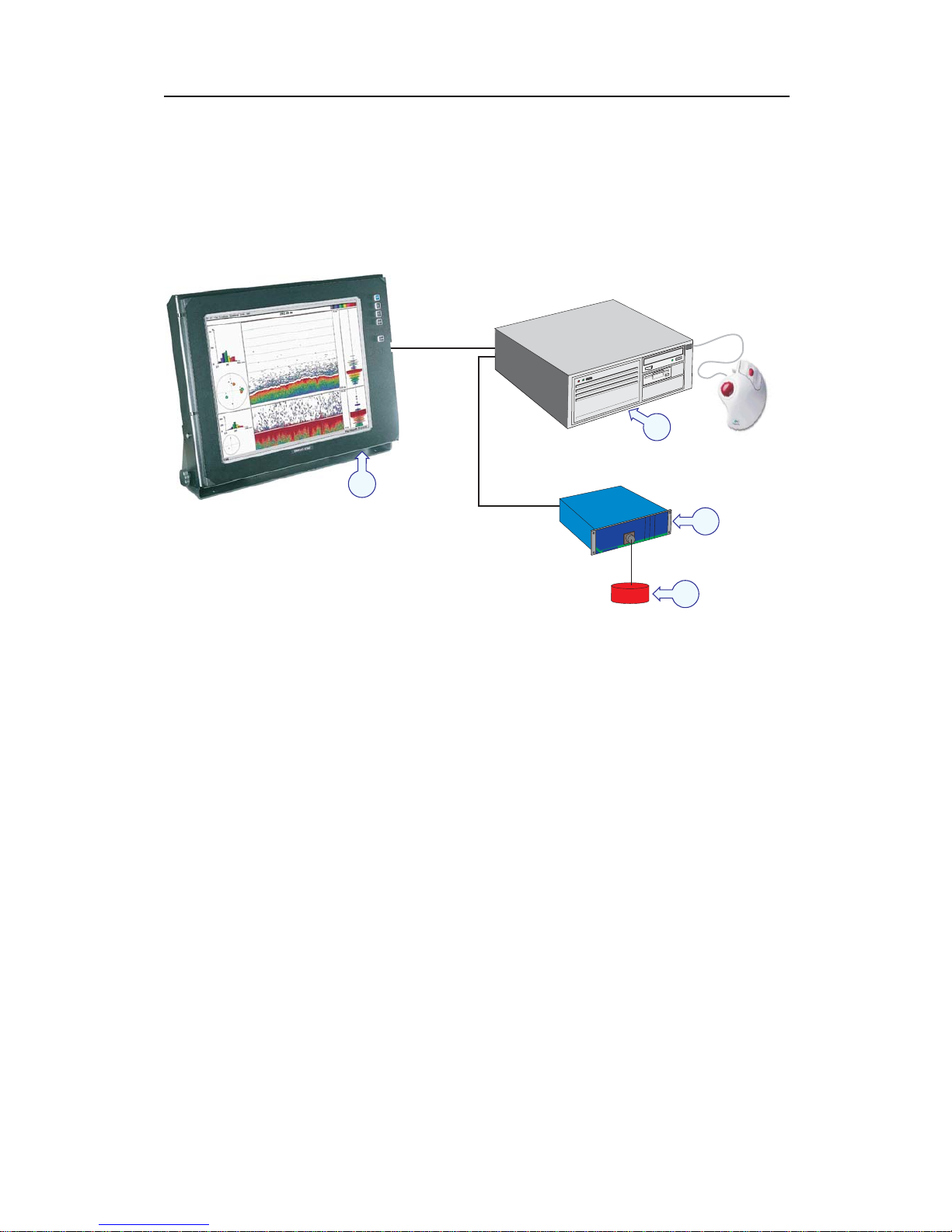
Simplified system diagram
Asimplified system diagram is shown below.
System diagram with one transceiver
SIMR
AD
G
PT
(CD010200D)
B
C
D
A
(A) = Colour monitor
(B) = Processor Unit (computer)
(C) = General Purpose Transceiver (GPT)
(D) = Transducer
10
304699/A

Introduction
General safety rules
TheSimradES60Fishfinding echo sounder system operates on
230 Vac 50/60 Hz.
WARNING
This voltage may be lethal!
The following safety precautions must be followed at all times
during installation and maintenance work:
• Always switch off all power before installation or
maintenance. Use the main circuit breaker, and label
the breaker with a warning sign that informs others that
maintenance or installation work is being carried out on the
system.
• Do not open the rack or cabinet doors while in rough seas. It
may swing open suddenly and cause damage or injury.
• For safety reasons during troubleshooting on the equipment
with power ON, two persons must always be present.
• Read and understand the first aid instructions for electric
shock.
• Whenever maintenance is carried out, it is essential that a fi
rst
aid kit is available, and that the maintenance personnel ar
e
familiar with the first aid instructions for electrical s
hock.
• The various parts of the system are heavy. Make sure
that
the appropriate tools and certified lifting equi
pment are
available, and that the personnel are trained i
n installation
and maintenance work.
304699/A
11

Simrad ES60
General supply conditions
The following supply conditions are applicable to this Simrad
ES60 Fish finding echo sounder delivery.
Equipment responsibility
The shipyard performing the installation and/or equipment dealer
becomes fully responsible for the equipment upon receipt unless
otherwise stated in the contract. The duration of responsibility
includes:
• The period of time the equipment is stored locally before
installation.
• During the entire installation process.
• While commissioning the equipment.
• The period of time between commissioning and the final
acceptance of the equipment by the end user (normally the
owner of the vessel which the equipment has been installed).
Unless other arrangements have been made in the contract, the
ES60 Fish finding echo sounder system guarantee period (as
specified in the contract) begins when the acceptance documents
have been signed
Receipt, unpacking and storage
Upon accepting shipment of the equipment, the shipyard and/or
the dealer should ensure that the delivery is complete and inspect
each shipping container for evidence of physical damage. If
this inspection reveals any indication of crushing, dropping,
immersion in water or any other form of damage, the recipient
should request that a representative from the company used to
transport the equipment be present during unpacking.
All equipment should be inspected for physical damage, i.e.
broken controls and indicators, dents, scratches etc. during
unpacking. If any damage to the equipment is discovered,
the recipient should notify both the transportation company
andSimrad so that Simrad can arrange for replacement or repair
of the damaged equipment.
Once unpacked, the equipment must be stored in a controlled
environment with an atmosphere free of corrosive agents,
excessive humidity or temperature extremes. The equipment
must be covered to protect it from dust and other forms of
contamination when stored.
For more information, refer to Equipment handling on page 15
12
304699/A

Introduction
General installation r equirements
The following installation requirements are applicable to this
Simrad ES60 Fish finding echo sounder delivery.
Approval by classification society
The ES60 Fish finding echo sounder transducer installation
must be approved by Det Norske Veritas (DNV) or another
classification society. The shipowner and shipyard performing
the installation are responsible for obtaining installation approval.
Supply power
The supply voltage to the equipment is to be kept within ±10% of
the installation’s nominal voltage. Maximum transient voltage
variations on the main switchboard’s bus-bars are not to exceed
-15% to +20% of the nominal voltage (except under fault
conditions).
Simrad recommends that the ES60 Fish finding echo sounder is
powered using an Uninterruptable Power Supply (UPS). The
UPS should have the capacity to independently maintain power
to the system for a minimum of 10 minutes. This ensures that the
system can be switched off in a controlled manner in t he event
of a power failure.
Compass deviation
Once the installation is complete, the vessel must be swung with
the system in both the operative and inoperative modes. The
shipowner and captain are responsible for updating the deviation
table accordingly with regard to the vessel’s national registry and
corresponding maritime authority.
Noise sources
The vessel’s hull, rudder(s) and propeller(s) s hould be thoroughly
inspected in dry dock prior to installation. Roughness below
the water-line deformities in the shell plating and protruding
obstacles can create underwater noise. These sources of
turbulence must be smoothed or removed as best as possible. It is
especially important that the propeller(s) is not pitted or damaged.
Dry docking
Make sure that ample clearance under the sonar trunk and/or
protection blister is provided when dry docking the vessel. Avoid
locating supporting blocks or structures in the vicinity of this
equipment.
304699/A 13

Simrad ES60
Note
The location of the transducer and/or protection blister must be
noted on the vessel’s docking plan for future reference.
Wiring
All cables running between system cabinets located in different
rooms and/or on different decks must be supported and protected
along their entire lengths using conduits and/or cable trays. Note
that the cables must not be installed in the vicinity of high-power
supplies and cables, antenna cables or other possible sources
of interference.
Whenever possible, transducer cables must be run in steel
conduits.
For more detailed information about cables and wiring, refer to
Basic cable requirements on page 80
14
304699/A

Introduction
Equipment handling
This section provides the basic rules for transportation, storage
and handling of units. In this c ontext, a unit may be any large or
small part of the system. It can be supplied as part of the initial
delivery, or as a spare part.
Transportation
Unless otherwise stated in the accompanying documentation,
electronic, electro-mechanical and mechanical units supplied
by Simrad can be transported using all methods approved for
delicate equipment; (by road, rail, air or sea). The units are to be
transported in accordance with general or specific instructions for
the appropriate unit(s), using pallets, transport cases, or carton
boxes as appropriate.
Note
Special local restrictions concerning air transportation may be
applied to units containing certain types of batteries. These
units must be checked properly, and the regulations must be
investigated by the packer/shipper before the unit is dispatched.
All local transportation must be carried out according to the same
specifications as for the initial delivery. In general, all units must
be handled with care.
The carton or case containing the unit must be kept dry at all
times, and must be sheltered from the weather. It must not
be subjected to shocks, excessive vibration or other rough
handling. The carton or case will normally be marked with text
or symbols indicating which way it is to be placed. Follow any
instructions given, and ensure the case is always placed with its
“top” uppermost.
The carton or case must not be used for any purpose for which it
was not intended (step, table, etc.), and in the absence of other
information, no other cartons or cases must be stacked on top
of it.
Lifting
A heavy crate will normally be marked with its weight, and the
weights of other cartons or crates will normally be entered on
the packing list.
• You must always check the weight of a crate before you
attempt to lift it.
• You must always use lifting apparatus that is approved and
certified for the load.
304699/A 15

Simrad ES60
Heavy units may be equipped with lifting lugs for transportation
by crane within the workshop or installation area. Before you
use a crane:
• You must check the applicable weight certificateforthecrane.
• You must check the security of the lifting lugs.
Ensure that all available lifting lugs are used. Ensure the unit
remains under control during the operation to avoid damage to
the unit, equipment or personnel.
Heavy units may be transported using a forklift truck. Special
attention must t hen be paid to the position of the unit’s centre of
gravity. The units must be properly secured to the truck.
Storage prior to installation or use
When a system, a unit or a spare part has been delivered to
the customer, it may be subject to long time storage prior
to installation and use. During this storage period, certain
specifications must be met. The equipment m ust be preserved
and stored in such a way that it does not constitute any danger
to health, environment or personal injury.
1 The equipment must be stored in its original transportation
crate.
2 Ensure that the units are clearly separated in the shelves and
that each unit is easily identifiable.
3 The crate must not be used for any purpose for which it was
not intended (eg. work platform etc.).
4 The crates must not be placed on top of each other, unless
specific markings permit this.
5 The crates must not be placed directly on a dirt-floor.
6 Do not open the crate for inspection unless special
circumstances permit so.
• “Special circumstances” may be suspected damage to the
crate and its content, or inspections by civil authorities.
• If any units are damaged, prepare an inspection report
stating the condition of the unit and actions taken.
Describe the damage and collect photographic evidence
if possible. Re-preserve the equipment.
• If the units are not damaged, check the humidity
absorbing material. If required, dry or replace the
bags, then re-pack the unit(s) according to the packing
instructions.
7 If the crate has been opened, make sure that is it clos
ed
and sealed after the inspection. Use the original p
acking
material as far as possible.
16
304699/A

Introduction
8 The storage room/area must be dry, with a non-condensing
atmosphere. It must be free from corrosive agents.
9 The storage area’s mean temperature must not be lower than
-30° C, and not warmer than +70° C. If other limitations
apply, the crates will be marked accordingly.
Note
Transducers must not be stored in temperatures below -20°
C, or higher than +60° C.
10 The crate must not be exposed to moisture from fluid
leakages.
11 The crate must not be exposed to direct sunlight or excessive
warmth from heaters.
12 The crate must not be subjected to excessive shock and
vibration.
13 If the unit contains normal batteries, these may have been
disconnected/isolated before the unit was packed. These
must only be reconnected before the installation starts. Units
containing batteries are marked.
Caution
Units containing lithium or alkaline batteries must
be handled separately and with care. Such units are
marked accordingly. Do not attempt to recharge
such batteries, open them or dispose of them by
incineration. Refer to the applicable product data
sheets.
Inspection
An inspection must be carried out immediately after the unit(s)
have arrived at their destination.
1 Check all wooden or cardboard boxes, plastic bags and
pallets for physical damage. Look for signs of dropping,
immersion in water or other mishandling.
2 If damage is detected externally, you will have to open the
packaging to check the contents. Request a representative of
the carrier to be present while the carton is opened, so any
transportation damage can be identified.
3 If any units are damaged, prepare an inspection report
stating the condition of the unit and actions taken. Describe
the damage and collect photographic evidence if possible.
Send the inspection report to Simrad as soon as possible.
304699/A 17

Simrad ES60
4 If the units are not damaged, check the humidity absorbing
material. If required, dry or replace the bags, then re-pack
the unit(s) according to the packing instructions.
Unpacking
General unpacking procedure
Normal precautions for the handling, transportation and storage
of fragile electronic equipment must be undertaken.
Note
If the unit is not to be prepared for immediate use, you may
consider storing it unopened in its original packing material.
However, it may be useful to open the case to check its contents
for damage and retrieve any accompanying documentation.
Do not use a knife to open cardboard cartons - the contents may
lie close to the surface, and may be damaged by the blade.
1 Check the carton before opening it to ensure it shows no
signs of dropping, immersion in water or other mishandling.
If the carton shows signs of such damage, refer to the
paragraph covering Inspection on receipt.
2 Place the carton on a stable work bench or on the floor with
the top of the carton uppermost.
3 In the absence of other instructions, always open the top
of the carton first. The contents will normally have been
lowered into the carton from above, so this will usually be
the easiest route to follow. Care must be used when opening
the carton to ensure the contents are not damaged. D
o not
use a knife to open cardboard cartons
4 If the carton has been closed using staples, remove the
staples from the carton as you open it. This will reduce the
possibilities of scratch injury to yourself and damage to the
contents.
5 If a wooden crate has been closed using screws, always
remove them using a screwdriver. Do not attempt to prise
the lid off with a crowbar or similar.
6 Once the carton is open, carefully remove all loose packing
and insulation material. Check for manuals and other
documents that may have been added to the carton during
packing, and put these to one side. Check also for special
tools, door keys etc.
18
304699/A

Introduction
Unpacking electronic an d electromechanical units
Electronic and electromechanical units will normally be wrapped
in a clear plastic bag. Lift the unit, in its bag, out of the carton
and place it in a stable position on the floor/work bench.
Inspect the unit for damage before opening the plastic bag.
Note
Beware of the dangers of Electro-Static Discharge (ESD) both
to yourself and to the equipment, when handling electronic units
and components.
Cables must never be used as carrying handles or lifting points.
Do not break the seal to open a circuit board package before
the board is to be used. If the board package is returned to the
manufacturer with the seal broken, the contents will be assumed
to have been used and the customer will be billed accordingly.
Assuming all is well, open the bag and remove the unit.
Open the unit and check inside. Remove any packing and
desiccant material that may be inside.
Unpacking m echanical units
Mechanical units may be heavy. Using a suitably certified lifting
apparatus, lift the unit out of the crate and place it in a stable
position on the floor/work bench.
Inspect the unit for damage and remove any packing material that
may be inside the unit.
Unpacking transducers
Transducers may be supplied mounted to a hull unit (if any), or
packed separately. Crates are normally identified by the order
number and the serial number.
The transducer face must be protected by a rigid, padded cover
(e.g. a wooden box lined with foam rubber) all the time it is
exposed to the risk of physical damage.
Caution
Once transducer is unpacked, great care must be taken
to ensure that transducer body and cabling is not
exposed to any mechanical stress.
304699/A 19

Simrad ES60
Storage after unpacking
The unit must whenever possible be stored in its original
transportation crate until ready for installation. The crate must
not be used for any purpose for which it was not intended (eg.
work platform etc.).
Once unpacked, the equipment must be kept in a dry, non
condensing atmosphere, free from corrosive agents and isolated
from sources of vibration.
Note
Do not break the seal to open a circuit board package before
the board is to be used. If the board package is returned to the
manufacturers with the seal broken, the contents will be assumed
to have been used and the customer will be billed accordingly.
The unit must be installed in its intended operating position as
soon as possible after unpacking. If the unit contains normal
batteries, these may have been disconnected/isolated before the
unit was packed. These must then be reconnected during the
installation procedure. Units containing batteries are marked.
Note
Units containing lithium or alkaline batteries must be handled
separately and with care. Such units are marked accordingly. Do
not attempt to recharge such batteries, open them or dispose of
them by incineration. Refer to the applicable product data sheets.
Storage after use
If a unit is removed from its operating location and placed into
storage, it must be properly cleaned and prepared before packing.
Cleaning cabinets
If a cabinet has been exposed to salt atmosphere while it was in
use, it must be thoroughly cleaned both internally and externally
to prevent corrosion.
1 Wipe the cabinet externally using a damp cloth and a little
detergent. Do not use excessive amounts of water as the
unit may not be water tight. On completion, dry the unit
thoroughly.
2 All surfaces must be inspected for signs of corrosion,
flaking/bubbling paint, stains etc. Damaged or suspect areas
must be cleaned, prepared and preserved using the correct
preservation mediums for the unit. The mediums to be used
will usually be defined in the units’ maintenance manual.
20
304699/A

Introduction
3 Open the unit, and using a vacuum cleaner, remove all dust
etc. from the unit. Great care must be taken to ensure the
circuit boards and modules are not damaged in the process.
Mechanical units
If a mechanical unit may has been exposed to a salt atmosphere
while it was in use, it must be thoroughly cleaned both internally
and externally to prevent corrosion.
1 If the construction materials and type of unit permits, wash
the unit using a high-pressure hose and copious amounts
of fresh water. Examples are the lower parts of hull units
(outside the hull) or subsea units
2 Ensure that all traces of mud and marine growth are
removed. Use a wooden or plastic scraper to remove
persistent growth, barnacles etc. On completion, dry the
unit thoroughly.
Caution
Do not use a high pressure hose in the vicinity of
cables or transducers. Do not use sharp or metal
tools on a transducer face.
3 If the materials or type of unit prevents the use of a
high-pressure hose, wipe the unit using a cloth dampened
with water containing a little detergent. Examples are the
upper parts of hull units (inside the hull) and hydraulic
systems
4 Do not use excessive amounts of water as some components
on the unit may not be water tight. Wipe off the detergent
with a damp cloth, then dry the unit thoroughly.
5 All surfaces must be inspected for signs of corrosion,
flaking/bubbling paint, stains etc. Damaged or suspect
areas must be cleaned, prepared and preserved using the
correct preservation mediums. The mediums t o be used will
normally be defined in the unit’s maintenance manual.
Cables
Wipe clean all exposed cables, and check for damage. If a cable
shows signs of wear or ageing, contact Simrad for advice.
Internal batteries
If the unit contains batteries, these may discharge slowly during
storage. If the unit is to be stored f or an extended period,
disconnect or remove all internal batteries.
304699/A
21

Simrad ES60
A suitable piece of insulating material can be placed between the
battery and the electrical contacts to prevent electrical discharge.
The battery can then remain in the unit, reducing the risk of it
being misplaced during the storage period.
Caution
Units containing lithium or alkaline batteries must be
handled separately and with care. Such units are
marked accordingly. Do not attempt to recharge such
batteries, open them or dispose of them by incineration.
Refer to the applicable product data sheets.
Dehumidifier
Place a suitably sized bag of desiccant material (silica gel or
similar) into the unit to keep the electronic components as dry
as possible.
Coatings
Spray the unit externally with a corrosion inhibitor (e.g. a light
oil) before packing.
Re-packaging
Whenever possible, the unit m ust be stored and transported in
its original packing material and/or crate. In the event that this
material is not available, proceed as follows:
• Small units must be protected from damp by being placed
within a plastic bag at least 0.15 mm thick. An appropriate
quantity of desiccant material should be placed inside this bag,
and the bag sealed. The sealed unit must then be placed in an
appropriate carton or crate, and supported in the container
by appropriate shock-absorbing insulation (polystyrene foam
chips etc.).
• Large units must be placed in a suitable cardboard box or
wooden crate. The unit must be protected against physical
damage by means of shock-absorbing insulation mats. The
box must be clearly marked with its contents, and must be
stored in a dry and dust-free area.
Circuit board packaging
Circuit boards are delicate items. They may work year after year
in an advanced product, but then fail due to a small spark of
static electricity. For this reason, it is very important that they are
properly handled and protected during shipping.
22
304699/A

Introduction
Beware of ESD!
When you handle electronic circuit boards, you must beware of
the dangers of electrostatic discharge (ESD), both to yourself and
to the equipment. In order to ensure safe transport and storage,
circuit boards and other electronic units will always be wrapped
in a clear plastic protective bag, and the bag will be sealed.
See also: What is ESD? on page 24.
Unpacking and handling circuit boards
To unpack a circuit board:
• Wherever possible, prepare a suitable workbench. It must
have an approved conductive service mat, and i t must be
connected directly to a reliable earth point via its earthing
cord. You must wear a wristband in direct contact with the
skin, and the wristband must be connected to the service mat.
• Lift the circuit board, in its protective bag, out of the carton
and place it in a stable position on the a floor/work bench.
• Inspect the unit for damage before you open the plastic bag.
• Do not break the seal to open a circuit board package before
the board shall to be used. If the board package is returned
with the seal broken, we will assume that the content has been
used, and we will bill you accordingly.
• Assuming all is well, open the bag and remove the unit.
• Take out and keep the documentation. You will need it if
the circuit board shall be returned to us. Also, remove any
packing and desiccant material that may be inside.
• Keep the protective plastic bag for future use.
Unpacking on board
When you are working on board a vessel, an “approved
conductive service mat” is often far away. As you still need to
unpack circuit boards, make sure that you do it in the instrument
room, or at another location where you have a steel deck. Keep
far away from the bridge or any other rooms w ith wall-to-wall
carpets! If possible, bring a wristband and ground yourself.
Returning a circuit board
If you wish to return a circuit board to us, observe the following
rules.
• Place the circuit board to be returned in the same protective
plastic bag as you originally received it in - or a protective bag
of similar ESD protection quality.
•D
O NOT use standard plastic bags, such as commercial
bubble wrap.
304699/A 23

Simrad ES60
• Fill in all the necessary information on the applicable
documentation and place it inside the bag.
• Seal the bag.
• Place the circuit board in a suitable carton, and secure it for
shipping.
Note
Failure to follow these rules may result in unserviceable circuit
boards.
Temperature protection
If the unit must be protected against extremes of temperature,
the carton/crate must be lined on all walls, base and lid with 5
cm thick polyurethane or polystyrene foam. These units will be
identified as delicate in the applicable documentation.
The package must then be clearly marked:
Must not be transported or stored in temperatures below -5
degrees Celsius.
Other units can normally be stored in temperatures between -30°
C and +70° C, refer to the system’s technical specifications for
details.
Transducers must not be stored in temperatures below -20° C
and above +60° C.
What is ESD?
Electro-Static Discharge (ESD) is the transfer of a n electrostatic
charge between two bodies at different electrostatic levels,
caused either by direct contact or induction by an electrostatic
field. The passing of a charge through an electronic device can
cause localised overheating, and it can also “puncture” insulating
layers within the structure of the device. This may deposit a
conductive residue of the vaporised metal on the device, and thus
create a short circuit. This may result in a catastrophic failure, or
degraded performance of the device.
ESD protection
Sensitive electronic circuit boards must be transported and
stored in protective packing bags. The circuit boards must
not be transported or stored close to strong electrostatic,
electro-magnetic or radioactive fields. If it is necessary to open
and touch the circuit board inside the protective bag, then the
following precautions must be taken:
24
304699/A

Introduction
• The working area must be covered by an approved conductive
service m at that has a resistance of between 50 kΩ and 2
MΩ, and is connected directly to a reliable e arth point via
its earthing cord.
• The service personnel involved must wear a wristband in
direct contact with the skin, connected to the service mat.
• Printed circuit boards must be placed on the c onductive
service mat during installation, maintenance etc.
• If, for any reason, it is necessary to move the circuit board
from the conductive service mat, it must be placed in an
approved antistatic transportation container (e.g. static
shielding bag) before transportation.
• During installation and servicing, all electrical equipment
(soldering irons, test equipment etc.) must be earthed.
304699/A 25

Simrad ES60
INSTALLATION PROCEDURES
This chapter provides the basic information required to install
the physical units.
Note
Physical installation of commercial units (computers, printers,
displays) is n
ot described in this manual. Refer to the applicable
user manual(s) provided with the product.
Topics
Basic procedure on page 26
Configuration on page 27
General Purpose Transceiver installation on page 31
ES60 Marine Computer installation on page 33
Basic procedure
This is the basic installation procedure.
1 Check that you have received all parts required for the
installation; cables, connectors, brackets etc.
2 Install the transducer(s) and the transducer cables according
to the guidelines in this manual and the drawings provided
with the transducer.
3 If applicable, install the two-wire cable for the temperature
sensing thermistor.
4 Mount the Processor Unit (computer) and the display using
the appropriate brackets.
5 Connect the computer and display cables:
• Power cable to display monitor.
• Power cable to computer.
• Video cable from computer to display monitor.
• Connect the pointing device (mouse or trackball)
6 Mount the General Purpose Transceiver using the
appropriate brackets.
7 Connect the cables:
• Transducer cable(s)
• Power cable(s)
• If applicable, connect the cable from the temperature
sensor.
• If available, install a two-wire cable for remote on/off of
the General Purpose Transceiver(s).
26
304699/A

Installation procedures
8 Prepare and install the ethernet cable(s) between the
General Purpose Transceiver(s) and the computer:
• An Ethernet cable must be used between the General
Purpose Transceiver and the computer.
• If only one General Purpose Transceiver is used, you
need a t wisted pair cable with swapped receive and
transmit wires. The cable is connected between the
transceiver and the computer.
• An Ethernet switch is required if your system includes
more than one General Purpose Transceiver. If a hub
is used, all ethernet cables must be of the “straight
through” type.
9 Prepare and install the required serial line interfaces.
• Connect navigation receiver, trawl system and heave
sensor with serial line output to the rear of the echo
sounder computer using RS-232 cables. Heave sensors
with an analog output are connected directly to the
Auxiliary connector of the nearest transceiver.
10 If required, prepare and install the synchronization cable(s).
• Synchronous transmission is desirable if there are
several echo sounders on-board the vessel. For every
echo sounder and every transceiver on-board the ship,
connect the appropriate pins at the
Auxiliary connectors
together using a two-wire cable.
Configuration
TheSimradES60Fishfinding echo sounder is designed as a
modular system. It supports a variety of configurations and
frequency options. The delivery may consist of:
• Transducer(s)
• General Purpose Transceiver(s) (GPT)
• Ethernet switch (if the system comprises more than one GPT)
• Processing Unit (computer)
• Display monitor
• Pointing device (mouse or trackball)
The computer, display monitor and pointing device may be
provided locally using standard commercial components.
Transducer
One or more transducers are included. A single frequency
General Purpose Transceiver will accept one transducer, while a
dual frequency transceiver will accept two transducers.
304699/A 27

Simrad ES60
A large number of transducers are available. There are several
transducer alternatives for each operating frequency with
different beam widths, power rating and mounting arrangements.
All transducers are rated 60 or 75 ohms. Each has an efficiency
of approximately 50%.
Related topics
Simrad transducers on page 143
Transducer Installation on page 110
General Purpose Transceiver (GPT)
One or more General Purpose Transceivers (GPT) are included.
A single frequency General Purpose Transceiver accepts one
transducer, while a dual frequency transceiver accepts two
transducers.
The General Purpose Tra
nsceiver is a small self-contained unit
containing its own po
wer s upply. It operates on +12 Vdc or
115-230 Vac. The uni
t can be mounted anywhere on board
the ship, provi
ded that the location is dry and ventilated We
recommend th
at it is mounted as close to the transducer(s) as
possible. P
ower cable and mounting brackets are enclosed.
An Ethernet link connects the General Purpose Transceiver
to the Processor Unit (computer). This link may comprise a
standard Ethernet cable and - if necessary - an Ethernet switch.
The transceiver includes its own Ethernet interface. A network
interface board must be fitted to the computer.
The General Purpose Transceiver is available in single beam
and split beam configurations. A dual frequency single
beam configuration is also provided. The possible operating
frequencies are listed in the technical specifications. Typical
configurations include:
• GPT-S38(4)-F (single beam 38 kHz, 4 kW)
• GPT-S50(4)-F (single beam 50 kHz, 4 kW)
• GPT-S70(1)-F (single beam 70 kHz, 1 kW)
• GPT-S120(1)-F (single beam 120 kHz, 1 kW)
• GPT-S200(1)-F (single beam 200 kHz, 1 kW)
• GPT-Q38(4)-F (quad (split) beam 38 kHz, 4 kW)
• GPT-Q120(4)-F (quad (split) beam 120 kHz, 4 kW)
• GPT-S38(1)/S50(1)-F (single beam 38 and 50 kHz, 1+1 kW)
Two or more General Purpose Transceivers can exist on the same
Ethernet cable. A multi-frequency sounder e merges simply by
using several transceivers on the Ethernet cable.
28
304699/A
 Loading...