

Page 1

Installation manual
TECHNOLOGY FOR SUSTAINABLE FISHERIES
www.simrad.com
Simrad ES38-12
38 kHz split-beam transducer
Page 2

Page 3

SimradES38-12
Installationmanual
Thisdocumentprovidesageneraldescriptionofhowto
installtheSimradES38-12Splitbeamtransducer.The
informationmustberegardedasgeneralguidelinesand
recommendationsonly.Theinstallationshipyardmust
designandmanufactureinstallationhardwaretotthe
ES38-12transduceroneachindividualvessel.
344276/A
17.02.2010
©
KongsbergMaritimeAS
Page 4

Documenthistory
Simraddocumentnumber:344276/ISBN-13:978-82-8066-119-7/Currentrevision:A
Rev.A15.022010
Copyright
©2010KongsbergMaritimeAS
TheinformationcontainedinthisdocumentremainsthesolepropertyofKongsbergMaritimeAS.Nopart
ofthisdocumentmaybecopiedorreproducedinanyformorbyanymeans,andtheinformationcontained
withinitisnottobecommunicatedtoathirdparty,withoutthepriorwrittenconsentofKongsberg
MaritimeAS.Thedocument,oranypartofit,maynotbetranslatedtoanyotherlanguagewithoutthe
writtenapprovalfromKongsbergMaritimeAS.
Firstversion.
Disclaimer
KongsbergMaritimeASendeavourstoensurethatallinformationinthisdocumentiscorrectandfairly
stated,butdoesnotacceptliabilityforanyerrorsoromissions.
Warning
Theequipmenttowhichthismanualappliesmustonlybeusedforthepurposeforwhichit
wasdesigned.Improperuseormaintenancemaycausedamagetotheequipmentand/orinjury
topersonnel.Theusermustbefamiliarwiththecontentsoftheappropriatemanualsbefore
attemptingtoinstall,operateorworkontheequipment.
KongsbergMaritimeASdisclaimsanyresponsibilityfordamageorinjurycausedbyimproper
installation,useormaintenanceoftheequipment.
Supportinformation
Ifyourequiremaintenanceorrepair,contactyourlocaldealer.Youcanalsocontactususingthefollowing
address:contact@simrad.com.Ifyouneedinformationaboutourotherproducts,visitourwebsite.On
thewebsiteyouwillalsondalistofourdealersanddistributors.
KongsbergMaritimeAS
www.kongsberg.com
Page 5

Installationmanual
Tableofcontents
ABOUTTHISMANUAL.......................................................5
SIMRADES38-12..............................................................6
WHERETOMOUNTTHETRANSDUCER...............................7
HOWTOINSTALLTHETRANSDUCER..............................11
Transducerinstallationinblister............................................................................11
Useamountingplatewheneverprovided.....................................................11
Smoothsurfaceisimportant........................................................................11
Example:Largecirculartransducer..............................................................12
Example:Mediumandlargetransducers,principle.......................................13
Example:Mediumandlargetransducers,detail............................................13
Commonguidelines....................................................................................14
Toe-in........................................................................................................14
Physicallocation.........................................................................................14
Transducerinstallationinboxkeel.........................................................................15
Usemountingplatewheneverprovided........................................................15
Smoothsurfaceisimportant........................................................................15
Example:Boxkeelinstallation....................................................................16
Transducerushmountedinasteeltank...............................................................16
Usemountingplatewheneverprovided........................................................16
Smoothsurfaceisimportant........................................................................16
Waterlled.................................................................................................16
Example:Flushmountinginasteeltank......................................................17
Transducerwithacousticwindow..........................................................................17
Usemountingplatewheneverprovided........................................................17
Smoothsurfaceisimportant........................................................................17
Example:Acousticwindow.........................................................................18
Transducermountedinsidethehull.......................................................................18
Usemountingplatewheneverprovided........................................................18
Smoothsurfaceisimportant........................................................................18
Example:Mountinginsidethehull..............................................................19
Transducermountedonadropkeel.......................................................................19
Retractabletransducer............................................................................................20
TOWEDBODYINSTALLATION.........................................21
Generalrequirements.............................................................................................21
Smoothsurfaceisimportant........................................................................21
Usemountingandclampingringswheneverprovided...................................21
Useamountingplatewheneverprovided.....................................................21
Installationinatowedbody...................................................................................22
344276/A
3
Page 6

SimradES38-12
Example:Smalltransducer..........................................................................23
Example:Mediumandlargetransducers......................................................23
Example:Dualtransducerarrangement........................................................24
STEELCONDUIT..............................................................25
TRANSDUCERHANDLINGANDMAINTENANCE................26
Rulesfortransducerhandling.................................................................................26
Rulesfortransducermaintenance..........................................................................27
Approvedanti-foulingpaintsfortransducers.........................................................28
Usingself-lockingtaps...........................................................................................28
IntroductiontoEmugeself-lockingthreads...................................................29
Drawingstandard........................................................................................30
Tapsandgauges..........................................................................................30
Self-locktapsprovidedbySimrad...............................................................31
Supplierandmanufacturer...........................................................................31
TRANSDUCERCABLESPLICING.......................................32
DRAWINGFILE...............................................................33
Echosounderconnections......................................................................................33
Splicingthetransducercable.......................................................................33
GeneralPurposeTransceiver(GPT)wiring...................................................34
GeneralPurposeTransceiver(GPT)transducerplugassembly.......................35
ES38-12Outlinedimensionsandinstallationdrawings.........................................36
Outlinedimensions[111337].......................................................................37
Mountingplate[111492].............................................................................38
Installationprinciples[111495]....................................................................39
4
344276/A
Page 7

Aboutthismanual
Aboutthismanual
Purpose
Thepurposeofthisinstallationmanualistoprovidethegenericdescriptionsand
illustrationsthatallowsyoutounderstandthebasicprinciplesforechosounder
transducerinstallation.
Abouttheinformationprovidedinthisdocument
Theinformationinthisdocumentmustberegardedasgeneralguidelinesand
recommendationsonly.Theinstallationshipyardmustdesignandmanufacture
installationhardwaretoteachindividualtransducerandvessel.
Approvalbymaritimeauthorities
Wheneverrequired,theinstallationshipyardmustalsohavetheinstallationapprovedby
theapplicablemaritimeauthorities.
Additionalinformation
Foradditionaldetailedinformationaboutthetransducertobeinstalled,refertothe
documentationprovidedwiththetransducer.Drawingsanddescriptionscanalsobe
obtainedfromh
t t p : / / w w w . s i m r a d . c o m .
344276/A
5
Page 8

SimradES38-12
SimradES38-12
Thepurposeofthismanualistheprovidethebasicinformationrequiredtoinstallthe
SimradES38-12Splitbeamtransducer.
Transduceranddocuments
•SimradES38-12:KSV-111497
•Datasheet:164276
•Drawings:
–Outlinedimensions:111337
–Mountingplate:111492
–Installationprinciples:111495
Note
Althoughdrawingsareprovidedtoexplaintheinstallationprinciples,theinstallation
shipyardmustprovidethenaldrawingsrequiredtotthetransducertoeach
individualvessel.Also,whenapplicable,theinstallationshipyardmusthavethe
drawingsandinstallationapprovedbythepropermaritimeauthorities.
ThedrawingsspecicfortheES38-12transducerarelocatedintheDrawingleon
page33.
Technicalspecications
RefertotheSimradES38-12datasheet.Youcanreadand/ordownloadthedatasheeton
t t p : / / w w w . s i m r a d . c o m .
h
Additionalpartsprovidedforinstallation
ThefollowingitemscanbesuppliedbySimradtofacilitateinstallation.Theitems
mustbeorderedseparately.
•Mountingplate:499–111492
6
344276/A
Page 9

Wheretomountthetransducer
Wheretomountthe
transducer
Asingleanswertothequestionwheretolocatethetransducercannotbegiven.It
dependsverymuchonthevessel’sconstruction,howthehullisshapedandhowthe
waterrunsalongthehull.Therearehoweveranumberofimportantguidelines,and
someoftheseareevenconicting.
Mountthetransducerdeep
Mountthetransduceratadeeppositiononthehull.Considerthesituationswhenthe
vesselisunloaded,andwhenitispitchinginheavyseas.
Thereareseveralreasonsforthis.
1Theupperwaterlayersoftheseacontainamyriadofsmallairbubblescreatedbythe
breakingwaves.Inheavyseastheupper5to10metresmaybelledwithair,and
thehighestconcentrationswillbenearthesurface.Airbubblesabsorbandreectthe
soundenergy,andtheymayinworstcasesblockthesoundtransmissionaltogether.
2Anotherreasontogodeepisthecavitationinfrontofhighpowertransducers.
Cavitationistheformationofsmallbubblesinthewaterduetotheresultinglocal
pressurebecomingnegativeduringpartsoftheacousticpressurecycles.The
cavitationthresholdincreaseswiththehydrostaticpressure.
3Thetransducermustneverbeliftedfreeofthewatersurface.Transmittinginto
openairmaydamagethetransducerbeyondrepair.Mountingthetransducerata
deeppositiononthehullpreventsthis.
4Ifthetransducerisliftedupfromthewaterduringheavyseas,itmaybedamaged
whenthehullstrikesbackattheseasurface.Thisisespeciallyimportantforlow
frequencytransducerswithlargefaces.
Mountthetransducerawayfromprotrudingobjectsonthehull
Objectsprotrudingfromthehull,suchaszincanodes,sonartransducersoreventhe
vessel’skeel,generateturbulenceandownoise.Holesandpipeoutletsarealso
importantnoisesources.Theymayactasresonantcavitiesamplifyingtheownoise
atcertainfrequencies.Donotplaceanechosoundertransducerinthevicinityofsuch
objects,andespeciallynotclosebehindthem.Forthesamereason,itisveryimportant
344276/A
7
Page 10

SimradES38-12
thatthehullareaaroundthetransducerfaceisassmoothandlevelaspossible.Even
tracesofsealingcompound,sharpedges,protrudingboltsorboltholeswithoutlling
compoundwillcreatenoise.
Mountthetransducerattheforwardpartofthehulltominimisetheeffectsfrom
theboundarywaterlayer
Whenthevesselforcesitswaythroughthesea,thefrictionbetweenthehullandthe
watercreatesaboundarylayer.Thethicknessoftheboundarylayerdependsuponvessel
speedandtheroughnessofthehull.Objectsprotrudingfromthehull,anddentsinthe
hull,disturbtheowandincreasethethicknessoftheboundarylayer.Theowinthis
boundarylayermaybelaminarorturbulent.Alaminarowisanicelyordered,parallel
movementofthewater.Aturbulentowhasadisorderlypattern,fullofeddies.The
boundarylayerincreasesinthicknesswhentheowgoesfromlaminartoturbulent.The
gurebelowillustratestheboundarylayerofavesselmovingthroughthewater.
Furthermore,airbubblesintheseawaterarepresseddownbelowthehullandmixed
intotheboundarylayer.Theboundarylayeristhinunderneaththeforwardpartofthe
vessel,andincreasesinthicknessasitmovestowardsaft.Ifthesidesofthehullare
steep,someoftheairbubblesintheboundarylayermayescapetotheseasurfacealong
thevesselsides.Itisourexperiencethatawideandatbottom,witharisingangleless
thanaround13degrees,ispronetogivingairproblemsforthetransducer.Inanycasea
transducerlocationintheforwardpartofthehullispreferredinordertominimisethe
inuenceoftheboundarylayer.
Figure1Boundarywaterlayer
ATurbulentow
BLaminarow
CAirbubblesinthewater
8
344276/A
Page 11

Wheretomountthetransducer
Mountthetransducerfarawayfromthepropellers
Thepropulsionpropelleristhedominantnoisesourceonmostshingvessels,research
vessels,merchantvesselsandpleasurecrafts.Thenoiseistransmittedthroughthesea
water.Forthisreason,thetransducershouldbeplacedfarawayfromthepropeller,
whichmeansontheforepartofthehull.Positionsoutsidethedirectlineofsightfrom
thepropellerarefavourable.Onsmallvesselswithshortdistancesitisadvisedtomount
thetransduceronthatsideofthekeelwherethepropellerbladesmoveupwards,because
thepropellercavitationisstrongestontheotherside.Thecavitationstartsmosteasily
whenthewaterowsinthesamedirectionasthepropellerblade,andthatistosome
degreethecaseatthatsideofthekeelwherethepropellerbladesmovedownwards.
Mountthetransducerfarawayfromthebowthrusters
Bowthrusterpropellersareextremelynoisy.Wheninoperation,thenoiseandcavitation
bubblescreatedbythethrustermaketheechosounderuseless,almostnomatterwhere
thetransducerisinstalled.Andwhennotinoperation,thetunnelcreatesturbulence,
andifthevesselispitching,thetunnelmaybelledwithairoraeratedwaterinthe
upperpositionandreleasethisinthelowerposition.Ingeneral,alltransducersmust
bethereforeplacedwellawayfromthebowthruster.However,thisisnotaninvariable
rule.Certainthrusterdesignscombinedwithitsphysicallocationonthehullmaystill
offersuitabletransducerlocationsnearthethruster.Ifyouareindoubt,consultanaval
architect.
Mountthetransducerwithaslightlyinclinedtransducerface
Ideally,thetransducerfaceshouldbemountedinparallelwiththeseasurfacewhen
thevesselisinnormaltrim,asthiswillprovidethemostaccurateechoinformation.
However,itisalsoveryimportantthatthew
a t e r o w overthetransducerfaceislaminar.
Inordertoensurelaminarow ,thetransducerfacemaybetiltedslightlyupwardsin
relationtothewaterow.Thisallowstheowingwatertomeetthefacedirectly,and
assureslaminarow.Theinclinationanglemusthoweverbedeterminedcarefully.The
anglemustbesmallontransducerswithnarrowbeamangles.Asaruleofthumb,mount
transducerswithbeamanglessmallerthansevendegreeswithminimuminclination
angle.Thesmallerbeamangleyourtransducerhas,thesmallertheinclinationanglecan
be.Ensurethatyoudonotmountthetransducerwithanegativeinclinationangle.This
maycauseturbulenceunderthetransducerface,andreducedechosounderperformance.
Summaryandgeneralrecommendations
Someoftheaboveguidelinesareconicting,andeachcasehastobetreatedindividually
inordertondthebestcompromise.Generallythepropellernoiseisthedominantfactor,
andarecommendedtransducerlocationisintheforepartofthehull,withmaximum
distancefromthebowequaltoonethirdofthetotallengthofthehullatthewaterline.
344276/A
9
Page 12

SimradES38-12
Figure2Generalrecommendationfortransducerlocation
ATransducer
BInclinationangle
CHulllengthat
waterline
DMaximum1/3of
thehulllengthat
waterline(C)
Ifthevesselhullhasabulbousbow,thismaywellbeagoodtransducerlocation,but
alsoheremustbetakenintoconsiderationtheowpatternoftheaeratedwater.Often
theforemostpartofthebulbispreferable.
Figure3Recommendedlocationofthetransducer
onabulboushull
AThruster
BTransducerlocation
10
344276/A
Page 13

Howtoinstallthetransducer
Howtoinstallthetransducer
Therearemanydifferentwaystomountthetransducer.Thesearetherecommended
methodstomountalargeandmediumsizedtransducerusingamountingplate.
Topics
•Transducerinstallationinblisteronpage11
•Transducerinstallationinboxkeelonpage15
•Transducerushmountedinasteeltankonpage16
•Transducerwithacousticwindowonpage17
•Transducermountedinsidethehullonpage18
•Transducermountedonadropkeelonpage19
•Retractabletransduceronpage20
Transducerinstallationinblister
Onerecommendedtransducerinstallationmethodisbymeansofablister.Theblister
mustbedesignedandmanufacturedbytheinstallationshipyardtotboththetransducer
body,andthevessel’ssizeandhullshape.
Useamountingplatewheneverprovided
Certaintransducersmaybeprovidedwithamountingplate,orwithdrawingstoallow
forlocalproductionofthis.
Themountingplateisweldedtotheholepreparedforthetransducer.Boltsthroughthe
transducerbodyintothemountingplatewillsecurethetransducer.
Smoothsurfaceisimportant
Mountingscrewsorboltsmustnotbeextrudingfromthetransducerorthearea
immediatelyaroundit.
Makesurethatthesurfaceofthetransducerface,theinstallationhardwareusedtomount
it,thehullplatingandtheputtyaroundthetransducerisasevenandsmoothaspossible.
Obstructionsonthesesurfaceswillcreateproblemswithturbulentow.
344276/A
11
Page 14

SimradES38-12
Example:Largecirculartransducer
Theillustrationbelowshowsatypicaltransducerblisterdesignedforalargetransducer.
Notethatduetothephysicalsizeofthetransducer,aU-shapedsupportbar(E)isused
tosupportthetransducer.Thepurposeofthissupportistopreventthetransducerfrom
beingpushedupintotheblisterinheavyseas.
Figure4Largecirculartransducer
AStreamlinedblister
BStiffeningrib
CDrainageholes
DInclinationangle
EU-shapedsupportbar(recommended
onlargetransducers)
FForward
GCableserviceloop
HStufngtube
IMinimum400mm
JRoundedcorners
KAiroutlet
12
344276/A
Page 15
Example:Mediumandlargetransducers,principle
Howtoinstallthetransducer
Figure5Mediumandlargetransducers
usingmountingplate
Thisillustrationshowsthe
installationprincipleofamedium
orlargetransducerusingamounting
plate.
AAiroutlet
BStreamlinedblister
CTransducercable
DTransducer
EMountingplate
FForward
Example:Mediumandlargetransducers,detail
Figure6Installationprinciple,
mediumandlargetransducers
AMountingring/plate
BHullplatingontowedbody
CTransducer
D“Clampingring”functionality
facilitatedbytransducerbody
EBolt
Thisillustrationshowstheinstallation
principleofamediumorlargetransducers
usingamountingringor-plate.Note
thataclampingringisnotrequired,asthe
transducerbodyisshapedtofacilitatethis
function.
344276/A
13
Page 16

SimradES38-12
Commonguidelines
Thebestperformanceisobtainedwithablisterheightof40cmormore.Astreamlined
shapeandroundededgesreducetheownoise.Averticalleadingedgeorfrontwill
guidetheaeratedwatertothesidesoftheblister.Theorientationoftheblistershould
followthewaterow.
Theinterioroftheblistermustbelledwithseawater.Usedrainageholesinthe
bottomandanairoutletonthetop.Thewaterpressurebehindthetransducerwillthen
compensatefortheoutsidepressureduringvesselmovementsinroughsea.
WerecommendthatlargediametertransducersarettedwithahorizontalU-shaped
supportbar.Thisbarcanthenbesecuredtothemountingringusingthreadedrods.
Thetransducercablepenetratesthehullinastufngtube.Leaveanadequateloopofthe
cablebehindthetransducerforeasymountingorremovalofthetransducer.
Toe-in
Figure7T oe-inprinciple
towardsthebow.
Theanglemustbechosentoallowformostefcientwaterow.Itwillvarywiththe
locationofthetransducer;thedepthbelowthehull,thedistancefromthebow,andthe
distancetothekeel.Typicalanglesarefrom0to3°ondeplacementhulls.Onplaning
hulls,theangleisnormallycloseto0°.
AKeel
BBlister
CT oe-inangle
Theprimaryconsiderationmustbetoallow
laminarwaterow.Inmostcasesthisis
achievedbydesigningtheblisterinparallel
withthekeel.However,iftheblisteris
locatedclosetothebow,thefrontofthe
blistermayhaveafewdegreestoe-in
Physicallocation
Theblisterisplacedononeofthesidesofthehull,andthedistancefromthekeelisa
tradeoffbetweenaclosedistancegivingaturbulentowofwaterinanarrowpassage,
andalargedistancebringingthetransducerhigherupandalsomoreaffectedbyvessel
roll.Normallyadistanceofapproximately1misagoodcompromise.
14
344276/A
Page 17

Howtoinstallthetransducer
Figure8Physicallocationofblister AKeel
BTransducerblister
CHorizontaldistancebetweenkeeland
blister
DV erticaldistancebetweentheblister
surfaceandthekeel
Observethehorizontalandvertical
distances(CandD)betweenthekeeland
thetransducerblister.Onamediumsized
vessel,thehorizontaldistance(C)should
beapproximately1meter.Theverticaldistance(D)mustingeneralbeassmallas
possible.Thisisimportanttopreventthekeelfromshadowingthetransducerbeam
inshallowwaters.
Transducerinstallationinboxkeel
Vesselswithaboxkeelmayusethisfortransducerinstallation.
Theboxkeelisalreadythedeepestpartofthevessel.Iftheboxkeelistoonarrowto
accommodatethetransducer,itcanbewidened,eithersymmetricallyortoonesideonly.
Inthelastcasetheinstallationcouldalsobedescribedasablistermergedintothekeel.
Usemountingplatewheneverprovided
Certaintransducersmaybeprovidedwithamountingplate,orwithdrawingstoallow
forlocalproductionofthis.
Themountingplateisweldedtotheholepreparedforthetransducer.Boltsthroughthe
transducerbodyintothemountingplatewillsecurethetransducer.
Smoothsurfaceisimportant
Mountingscrewsorboltsmustnotbeextrudingfromthetransducerorthearea
immediatelyaroundit.
Makesurethatthesurfaceofthetransducerface,theinstallationhardwareusedtomount
it,thehullplatingandtheputtyaroundthetransducerisasevenandsmoothaspossible.
Obstructionsonthesesurfaceswillcreateproblemswithturbulentow.
344276/A
15
Page 18

SimradES38-12
Example:Boxkeelinstallation
Figure9Boxkeelinstallation
Thegureillustratesa
symmetricalboxkeelinstallation.
ABoxkeel
BU-shapedsupportbar
(onlyrecommendedonlarge
transducers)
CStufngtube
DCableinsteelconduit
ECableserviceloop
Transducerushmountedinasteeltank
Flushmountingisusedonverylargevesselswithahullsodeepthatnoairbubblesare
foundbelowthehull,andonvesselsoperatinginshallowharboursorwaters,where
aprotrudingblistercannotbeaccepted.
Thestandardprocedureforushmountingonasteelvesselistoweldasteeltankinside
thehull,andmountthetransducerintothistank.
Usemountingplatewheneverprovided
Certaintransducersmaybeprovidedwithamountingplate,orwithdrawingstoallow
forlocalproductionofthis.
Themountingplateisweldedtotheholepreparedforthetransducer.Boltsthroughthe
transducerbodyintothemountingplatewillsecurethetransducer.
Smoothsurfaceisimportant
Mountingscrewsorboltsmustnotbeextrudingfromthetransducerorthearea
immediatelyaroundit.
Makesurethatthesurfaceofthetransducerface,theinstallationhardwareusedtomount
it,thehullplatingandtheputtyaroundthetransducerisasevenandsmoothaspossible.
Obstructionsonthesesurfaceswillcreateproblemswithturbulentow.
Waterlled
Asforablister,theinteriorofthetankmustbelledwithwater.
16
344276/A
Page 19
Howtoinstallthetransducer
Thiscanbeaccomplishedbyairreleasethroughasteeltube,whichisextendedeither
toopenair1.5mabovethewaterlineortothewateroutsidethehullatapointhigher
thanthetankinterior.
Ifthetubeisextendedtoopenair,drainagemustbeprovidedwithleakageatthe
transducerangeoraseparateholeinthetankbottom.
Example:Flushmountinginasteeltank
Figure10Flushmountinginasteeltank
ASteeltank
BWater
CDrainagehole
DCableserviceloop
ESteeltubeforairoutlet
FStufngtube
GCableinsteelconduit
Thegureillustratesthe
installationprincipleswhenthe
transducerismountedinasteel
tank.
Transducerwithacousticwindow
Vesselsoperatinginarcticwatersneedspecialattentionontransducerinstallation.
Floatingblocksoficemaydamageevenaushmountedtransducerface.Forthis
situationSimradoffersarctictanksindifferentsizes.
Usemountingplatewheneverprovided
Certaintransducersmaybeprovidedwithamountingplate,orwithdrawingstoallow
forlocalproductionofthis.
Themountingplateisweldedtotheholepreparedforthetransducer.Boltsthroughthe
transducerbodyintothemountingplatewillsecurethetransducer.
Smoothsurfaceisimportant
Mountingscrewsorboltsmustnotbeextrudingfromthetransducerorthearea
immediatelyaroundit.
Makesurethatthesurfaceofthetransducerface,theinstallationhardwareusedtomount
it,thehullplatingandtheputtyaroundthetransducerisasevenandsmoothaspossible.
Obstructionsonthesesurfaceswillcreateproblemswithturbulentow.
344276/A
17
Page 20

SimradES38-12
Example:Acousticwindow
Figure11Acousticwindow
polycarbonate.Thetankislledwithoil.
ASteeltank
BOil
CAcousticwindow
DCableserviceloop
EStufngtube
FCableinsteelconduit
GOilinlet
Thetransducershowninthegureis
mountedinsidethetankbehindastrong
acousticwindow.
Thewindowistypicallymadeof
Transducermountedinsidethehull
Thetransducercanalsobemountedinsidethehull.
Aninstallationofthetransducerinsidethehull,andsoundingthroughthehull,requiresa
goodacousticcontactbetweenthetransducerfaceandthehull.Buildatankaroundthe
transducerandllitwithaliquid.Oilusedinhydraulicsystemsisawellsuitedliquid
forthispurpose.Itcontainsnogasbubblesandisnon-corrosive.
Typicalvaluesofthetwowaylossare3dBforpolyester,6dBforaluminiumand10dB
forsteel.Hullsmadeofwoodorasandwichtypewithfoaminthemiddle,attenuate
thesoundsomuchthatthroughhullsoundingmustberegardedasimpossible.Theloss
varieswiththedistancebetweentransducerfaceandthehull.Thebestresultisobtained
whenthedistanceishalfawavelength.ConsultSimradforadvice.Inadditiontothe
loss,thebeampatternisdegraded,becausealargerareaofthehullissetintovibrations.
Usemountingplatewheneverprovided
Certaintransducersmaybeprovidedwithamountingplate,orwithdrawingstoallow
forlocalproductionofthis.
Themountingplateisweldedtotheholepreparedforthetransducer.Boltsthroughthe
transducerbodyintothemountingplatewillsecurethetransducer.
Smoothsurfaceisimportant
Mountingscrewsorboltsmustnotbeextrudingfromthetransducerorthearea
immediatelyaroundit.
18
344276/A
Page 21

Howtoinstallthetransducer
Makesurethatthesurfaceofthetransducerface,theinstallationhardwareusedtomount
it,thehullplatingandtheputtyaroundthetransducerisasevenandsmoothaspossible.
Obstructionsonthesesurfaceswillcreateproblemswithturbulentow.
Example:Mountinginsidethehull
Figure12Mountinginsidethehull
Thetransducershowninthegureismountedinsidethehull.Thetankislledwithoil.
ASteeltank
BOil
CHullplating
DCableserviceloop
EStufngtube
FCableinsteelconduit
GHoleforoillling
HAiroutlet
Transducermountedonadropkeel
Theuseofadropkeelwiththepurposeofstabilisingthevesseliswellknown.
Figure13Dropkeelinstallation
AInstrumentkeel
shaft
BLoweredposition
CBottomview
Adropkeelisalso
asuperiorplatform
forechosounder
transducers.Such
instrumentkeelshave
beenbuilt,mainlyon
researchvessels,often
protrudingasfaras
threemetersbelowthe
hull.Atthatdepth,the
waterisfreeofairbubblesuptoveryhighseastates.Thevesselisthenabletoperform
reliableacousticmeasurementsinopenseaalargerpartoftheyear.
344276/A
19
Page 22

SimradES38-12
Retractabletransducer
Hullunitsallowingthetransducertobeloweredandhoistedarecommonlyusedfor
horizontallookingsonars.Whennotinuse,thetransducerisretractedintoatrunk.
Figure14Retractable
transducer
ATransducer
BTrunk
CTransducershaft
DTransducershaftsleeve
EKeel
Theretractablehullunitismoreexpensivethan
ablister,butonvesselswithahullwhereitis
difcultorimpossibletoinstallablister,itmay
stillbeworthwhile.Theprinciplesofahullunit
witharetractabletransducerisshownbelow.
Vesselswithoutakeelandwithawide,atbottom
isanexamplewherearetractablehullunitcanbe
theonlyacceptablemethodforbringingtheecho
soundertransducerbelowtheboundarylayer.
20
344276/A
Page 23

Towedbodyinstallation
Towedbodyinstallation
Thesearetherecommendedmethodstomounttransducersinatowedbody.
Topics
•Generalrequirementsonpage21
•Installationinatowedbodyonpage22
Generalrequirements
Smoothsurfaceisimportant
Mountingscrewsorboltsmustnotbeextrudingfromthetransducerorthearea
immediatelyaroundit.
Makesurethatthesurfaceofthetransducerface,theinstallationhardwareusedtomount
it,thehullplatingandtheputtyaroundthetransducerisasevenandsmoothaspossible.
Obstructionsonthesesurfaceswillcreateproblemswithturbulentow.
Usemountingandclampingringswheneverprovided
Circulartransducersmaybeprovidedwithmountingandclampingrings,orwith
drawingstoallowforlocalproductionofthese.
Themountingringisweldedtotheholepreparedforthetransducer,whiletheclamping
ringtsaroundtheedgeofthetransducerbody.Boltsthroughtheclampingringintothe
mountingringwillsecurethetransducerbetweenthem.
Notethatseveraltransducersusedirectionguidestoallowcorrectmounting.
Useamountingplatewheneverprovided
Certaintransducersmaybeprovidedwithamountingplate,orwithdrawingstoallow
forlocalproductionofthis.
Themountingplateisweldedtotheholepreparedforthetransducer.Boltsthroughthe
transducerbodyintothemountingplatewillsecurethetransducer.
344276/A
21
Page 24

SimradES38-12
Installationinatowedbody
Transducersdesignedtowithstandlargewaterpressureareprovidedforuseintowed
bodies.
Therecommendedinstallationmethodisthroughthehullplatinghullusingamounting
plate,orwithmountingandclampingrings.Theinstallationarrangementonthetowed
bodymustbedesignedbythemanufacturerofthetowedbodytotitsshapeand
characteristics.
22
344276/A
Page 25

Example:Smalltransducer
Towedbodyinstallation
Figure15Smalltransducerwith
mountingandclampingrings
AMountingring
BHullplatingontowedbody
CTransducer
DClampingring
EBolt
Thisillustrationshowstheinstallation
principleofasmallcirculartransducerusing
clampingandmountingrings.
Example:Mediumandlargetransducers
Figure16Installationprinciple,
mediumandlargetransducers
AMountingring/plate
BHullplatingontowedbody
CTransducer
D“Clampingring”functionality
facilitatedbytransducerbody
EBolt
Thisillustrationshowstheinstallation
principleofamediumorlargetransducers
usingamountingringor-plate.Note
thataclampingringisnotrequired,asthe
transducerbodyisshapedtofacilitatethis
function.
344276/A
23
Page 26
SimradES38-12
Example:Dualtransducerarrangement
Figure17Dualtransducerarrangement
Thisillustrationshows
atypicalthroughthehull
installationofsmalland
largecirculartransducers
onatowedbody.
ASmalltransducer
BMediumorlarger
transducer
CElectronic
equipmentin
watertight
compartment
24
344276/A
Page 27

Steelconduit
Whyusesteelconduits?
Itisstronglyrecommendedtolayasteelconduitfromthetransducer’scablegland
totheechosoundertransceiver,andtopullthetransducercablethroughthisconduit.
Thereareseveralreasonsforthis.
•Itwillmakeiteasieratalaterstagetoreplacethetransducer.
Steelconduit
•Noiseandinterferencefromotherelectricalequipmentisgreatlyreduced.
•Theriskofoodingisgreatlyreducedifthepipeisterminateabovethewaterline.
WithasteelconduittheinstallationwillsatisfytheEUregulationsforEMCinterference.
Withoutasteelconduit,thereisariskofreducedechosounderperformance.
Steelconduitsqualitiesandshielding
Thesteelconduitmustbeunbrokenandwatertightfromthetransducertoabovethe
waterline.Fromthere,thecablecanbepulledfurther,orajunctionboxcanbeinstalled
tofacilitatefurtherconnections.Notethatthesteelconduitmustactasacontinuous
electricalscreenalltheway.
Steelconduitdimensions:
•minimum35mminnerdiameter
•minimum6mmwallthickness(4.5mmifgalvanised)
Morethatonetransducercable?
Iftwoormoretransducersareinstalledclosetoeachotheritispossibletopulltheir
cablesinthesamesteelconduit,providedtheconduitdiameterisincreasedaccordingly.
However,foreasyreplacementitisrecommendedthateachtransducerhasitsown
steelconduit.
344276/A
25
Page 28

SimradES38-12
Transducerhandlingand
maintenance
YouMUSTobservethefollowingrulesforhandling,maintenanceandpainting.
Topics
•Rulesfortransducerhandlingonpage26
•Rulesfortransducermaintenanceonpage27
•Approvedanti-foulingpaintsfortransducersonpage28
•Usingself-lockingtapsonpage28
Rulesfortransducerhandling
Note
Donotliftthetransducerbythecable.
Donotexposethetransducertodirectsunlight.
Donotexposethetransducertoexcessiveheat.
Transportprotection
Sometransducersaredeliveredwithacoverplateonthefaceforprotectionduring
transport.Letthisplatestayonaslongaspossible,butdonotforgettoremoveitbefore
thevesselgoesintothesea.
Paintingthetransducerface
Ananti-foulingpaintmaybeappliedtothetransducerface.Becausesomepainttypes
maybeaggressivetothepolyurethaneinthetransducerface,pleaseconsultSimrad’slist
ofapprovedpaints.SeeApprovedanti-foulingpaintsfortransducersonpage28.
26
344276/A
Page 29

Transducerhandlingandmaintenance
Cleaningthetransducerface
Wheneveropportunityarise,forexamplewhenthevesselisdrydocked,thetransducer
facemaybecleanedforshellsandothermarinefouling.B e c a r e f u l n o t t o m a k e c u t s i n
t h e t r a n s d u c e r f a c e . Useapieceofsoftwoodoraverynegradeemerypaper.
Specialrulesforacousticwindows
Arctictankshaveacousticwindowsmadeofpolycarbonate.T
p a i n t e d n o r c l e a n e d w i t h c h e m i c a l s . Acousticwindowsmustnotbeexposedtodirect
sunlight.
h e s e m u s t n e i t h e r b e
Rulesfortransducermaintenance
Onceinstalled,thetransducerismaintenancefree.However,whenthevesselisdocked,
itishighlyrecommendedtocleanthetransducerfacetoremovemarinegrowth.
1Performathoroughvisualcheckofthetransducer.
2Ifnecessary,cleanthetransducer
•Tocleanthetransducer,usenormalsyntheticsoapandwater.
•Toremovemarinegrowth,usene-gradesandpaperoremerypaper.
Note
D o n o t usestrongsolvents.
o n o t attempttoscrapeofmarinegrowthwithsheetsofmetal,screwdriversor
D
othermetallictools.
o n o t usehighpressurewatertocleanthetransducer .
D
3Ifnecessary,applyanewlayerofanti-foulingpainttothetransducerface.
Becausesomepainttypesmaybeaggressivetothepolyurethaneinthetransducer
face,pleaseconsultSimrad’slistofapprovedpaints.
→Approvedanti-foulingpaintsfortransducersonpage28
344276/A
27
Page 30

SimradES38-12
Approvedanti-foulingpaintsfortransducers
ThisisSimrad’slistofapprovedantifoulingpaintsonpolyurethanetransducerhousing.
Jotun
Headofceaddress:P .O.Box2021,N-3248Sandefjord,Norway
Website:w
1Racing
2Non-stop
3SafeguardUniversalprimer(125micron)withAntifoulingSeaQuantumUltra(125
micron)
4AntifoulingSeaguardian
InternationalMarineCoatings
Address:World-wideofces
Website:w
1Intersleektiecoat+425FCS
•BXA386/BXA390/BXA391Grey
•HKA563/HKA570/HKA571Y ellow
•MixBXA386,BXA390andBXA391rst,thenapply.Whendry,mixHKA563,
2Intersmooth360EcoloexSPC
3MicronExtra
w w . j o t u n . c o m .
w w . i n t e r n a t i o n a l - m a r i n e . c o m .
HKA570andHKA571,apply .
HempelIFACoatings
Headofceaddress:HempelA/S,Lundtoftevej150,Kgs.Lyngby ,DK-2800
Copenhagen,Denmark
Website:w
1HempelA/FClassic76550
Note
Refertothemanufacturer’sdocumentationanddatasheetsforacompleteprocedure.
w w . h e m p e l . c o m .
Usingself-lockingtaps
Screwconnectionsaregenerallymadesothattheycanbeloosenedagain.However,
accidentalloosening,especiallyunderdynamicstress,mustbeavoided.Forthisreason
itisoftennecessarytouseadditionallockingdevices.Theseareoftenexpensive,they
canbeusedonceonly,orreactcriticallytotemperaturechanges.
28
344276/A
Page 31
Transducerhandlingandmaintenance
IntroductiontoEmugeself-lockingthreads
Emugeself-lockisatapdesignwithanintegratedlockingfeature.Standardmetricbolts
areused.Theinternalthreadprovidesaself-lockingconnection,whichcanbeused
repeatedly.Itisnotnecessarytoinvolveasecondarylockingdevice(e.g.chemical,
nylonormechanical).TheEmugeself-lockboltswithstandvibrationsbetterthanstandard
(metric)threads,becausethethreadcontactstopsthesidewaysmovement.Thespecial
designoftheinternalthreadprolealsoprovidesamoreevendistributionofthe
tighteningstressoverthewholethreadlength.Theassemblyisjustaseasyaswitha
normal(metric)thread.Thereisnogeneralapplicablestandard(e.g.DINstandard)
fortheEmugeself-lockthread.
Figure18Example,internalandexternalthreads
AEmuge’ ssaw-toothproleuptopitchP≤0.7mm
BEmuge’ssaw-toothproleuptopitchP≥0.7mm
CStandardthread
1Externalthread
2Internalthread
Advantages
•Thethreadlockingfeatureisintegratedintheinternalthread
•Modiedprolewithrampsurfaceinthedirectionofstress
•30degreerampsurfaceprovidesself-lockingeffect
•Easyassembly
•Noassemblyerrors(forgettingthelockingdevice)possible
•Useofstandardexternalthreads(screws)withtoleranceclass“medium”
•Evendistributionofstressoverthewholethreadlength
•Nostrippingofthreads
•Economicallyefcientlockingsystem,noadditionalcomponentsarenecessary
•Undiminishedholdingpowerevenunderdynamicstress
•Repeatedlooseningandre-tighteningwithoutlossoffunction
344276/A
29
Page 32

SimradES38-12
•InternalthreadscanbeproducedwithEmugetaps,coldformingtapsorthreadmills
•Largerthreadholediameters,i.e.increasedtoollifeforthreadingtools
•Largertolerancesforthreadholediameters
Drawingstandard
Wheneverself-lockingthreadsarerequired,thisisshownonthetechnicaldrawing.
Inthecaseoftappingthroughholes,thearrowattheendofthecenterlineillustrates
thescrew-indirectionofthebolt.
Figure19Drawingexamples,self-lockingthread
Thedrawingisnormallyprovidedwiththefollowingtext(orsimilar):
Note:Theself-lockthreadsmarkedwithSL*mustbemadeinaccordancewith
procedure842–202125.Drilldiametersforthreadsdifferfromstandard.Self-lock
tapscanbesuppliedbySimrad.
Tapsandgauges
Thepretensionlockingthreadself–lock(taps)frommanufacturerEmugemustbeused.
30
344276/A
Page 33

Transducerhandlingandmaintenance
Figure20Exampleofuse
Note
InthecaseoftappingthroughholesitisimportantthattheproleoftheEmugeself-lock
threadsisinthecorrectdirectioncomparedwiththeenteringdirectionofthebolt.
UseEmugeself-lockgauges.Notethatthegaugemustbeusedinthecorrectdirection.
Self-locktapsprovidedbySimrad
Thefollowingself-locktapsareonstockatSimrad,andcanbeorderedfromus.
Threads
M6ø5.2700-078838
M8ø7.0700-078531
M10ø8.8700-078408
M12ø10.7700-078409
M16ø14.5700-078410
Drilldiameterforthreads
Part.no
Supplierandmanufacturer
Norwegiansupplieris:
TingstadAS,P .O.Box83,Kalbakken,0902Oslo,Norway
h
t t p : / / w w w . t i n g s t a d . n o
Manufactureris:
EMUGE-WerkRichardGlimpel,NurnbergerStrasse96-100,D-90607Lauf,Germany
h
t t p : / / w w w . e m u g e . d e
344276/A
31
Page 34

SimradES38-12
Transducercablesplicing
Ifyouneedtocutorlengthenthetransducercable,youmustspliceitcorrectly.The
cablebetweenthejunctionboxandthetransceivermustthenbesuppliedbySimrad,
andthismustbethesametypeasusedonthetransducer(s).Tosplicethecable,usea
metaljunctionboxwithEMCcableglandsandaterminalblock.Theterminalblock
mustprovidesolidfasteningofthecableendsaswellassufcientinsulationbetween
thewires.Werecommendthatthecablescreenisconnectedtothejunctionboxchassis
usingtheEMCcableglands,butifyoudothis,thejunctionboxchassism
connectedtovessel’sground.
u s t n o t be
Note
D o n o t solderthewirestogetherwithonlyelectricaltapeforinsulation.Thiswillresult
inelectricalnoiseandreducedoperationalperformance.
o n o t connectthecablescreentothevessel’ sground.
D
32
344276/A
Page 35

Drawingle
Thischaptercontainsrelevantdrawingsrelatedtotheelectricalandphysicalinstallation
oftheSimradES38-12Splitbeamtransducer.
Note
Themechanicaldrawingsareforinformationandguidanceonly.Theyarenotinscale,
andmaydifferslightlyfromtheoriginaldrawings.Alldimensionsareinmmunless
otherwiseisnoted.
Drawingle
TheoriginalinstallationdrawingsareavailableonPDFand/orDWG(AutoCad)format.
Visitw
Topics
•Echosounderconnectionsonpage33
•ES38-12Outlinedimensionsandinstallationdrawingsonpage36
w w . s i m r a d . c o m todownload.
Echosounderconnections
ObservethefollowinginformationrelatedtoelectricalconnectionoftheES38-12Split
beamtransducer.
Splicingthetransducercable
Ifyouneedtosplicethetransducercable,itisveryimportanttousethecorrectcable,
andtoavoidgroundloops.Westronglyrecommendtheuseofajunctionbox.Wealso
recommendthatyouinstallthetransducercableinasteelconduit.
Formoreinformation,see:
•Transducercablesplicingonpage32
•Steelconduitonpage25
•GeneralPurposeTransceiver(GPT)transducerplugassemblyonpage35
344276/A
33
Page 36

SimradES38-12
GeneralPurposeT ransceiver(GPT)wiring
ObservethedrawingbelowtoconnecttheSimradES38-12Splitbeamtransducertothe
GeneralPurposeTransceiver(GPT).Formoreinformationabouttheseconnections,
refertotheapplicableechosounderinstallationmanual.
34
344276/A
Page 37

GeneralPurposeT ransceiver(GPT)transducerplugassembly
Drawingle
344276/A
35
Page 38

SimradES38-12
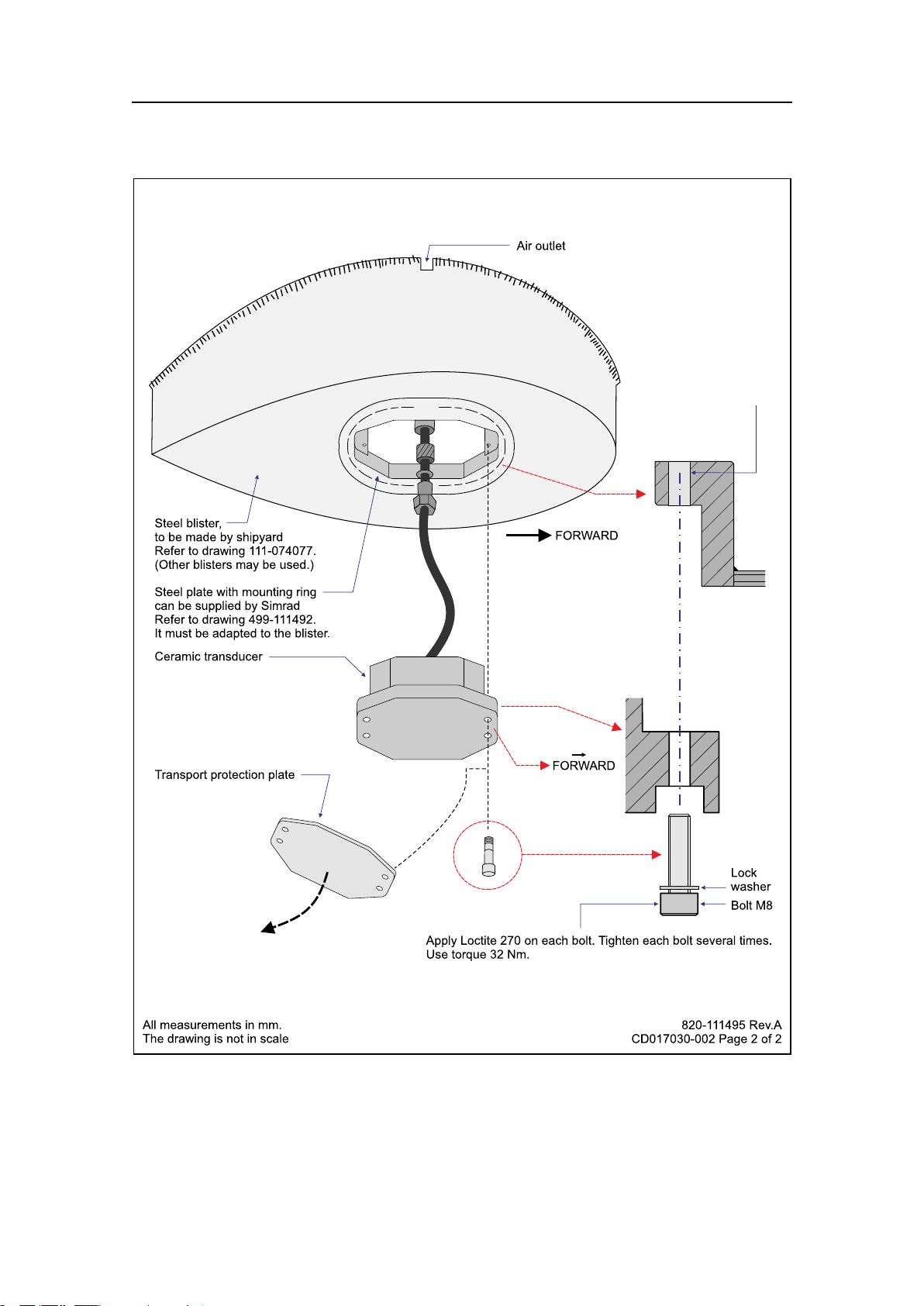
ES38-12Outlinedimensionsandinstallation drawings
Note
Whenyoufastenthetransducertothemountingplate,applyLoctite270oneachbolt,
andtightentheboltsseveraltimes.Usemaximumtorque32Nm.
Topics
•Outlinedimensions[1 11337]onpage37
•Mountingplate[1 11492]onpage38
•Installationprinciples[1 11495]onpage39
36
344276/A
Page 39

Outlinedimensions[111337]
Drawingle
344276/A
37
Page 40

SimradES38-12
Mountingplate[111492]
38
344276/A
Page 41

Installationprinciples[111495]
Drawingle
344276/A
39
Page 42
SimradES38-12
40
344276/A
Page 43

Index
Index
A
About,5
informationinthis
manual,5
Acousticwindow,27
example,18
installation,17
Additionalinformation,5
Airoutlet
example,12
Anti-fouling
paint,28
Approval
maritimeauthorities,5
B
Blister
Commonguidelines,14
installation,11
physicallocation,14
Boundarywaterlayer,8
Bowthrusters
noise,9
Boxkeel
example,16
installation,15
C
Cable
transducer,splicing,32
Clampingring
example,12,23
Clampingrings,21
Cleaning
transducerface,27
Commonguidelines
blister,14
Conduit
steel,25
D
Diameter
steelconduit,25
Dimensions
drawing,37
Drawing
GPTTransducerplug,35
Mountingring,38–39
outlinedimensions,37
Drawingle,33
E
EMCinterference,25
Emuge,29
Example
Acousticwindow,18
Airoutlet,12
boxkeel,16
Clampingring,12,23
ushmounting,17
Insidethehull,19
Mountingplate,13,23
Mountingring,12–13,23
Streamlinedblister,12
F
Flushmounting
example,17
steeltanl,16
G
GeneralPurpose
Transceiver
transducerplug,35
wiring,34
GPT
wiring,34
GPTTransducerplug
drawing,35
Groundloops
avoiding,33
H
Handling,26
Handlingrules
transducer,26
Heat,excessive
doNOTexpose
transducer,26
HempelIFACoatings,28
I
Important
smoothsurface,11,
15–18,21
Inclination
angle,9
Insidethehull
example,19
installation,18
Installation
drawings,6,33
hardware,6
responsibility,6
Installationmethod
Acousticwindow,17
Blister,11
Boxkeel,15
Flushmounting,16
Insidethehull,18
Steeltank,16
InternationalMarine
Coatings,28
Introduction,6
J
Jotun,28
Junctionbox
cablesplicing,33
L
Lifting
transducer,26
Location
recommendation,9
M
Maintenance,26
Maintenancerules
transducer,27
Maritimeauthorities
approval,5
Mountingplate,11,15–18,21
example,13,23
Mountingring
drawing,38–39
example,12–13,23
Mountingrings,21
N
Noise
boundarywaterlayers,8
bowthrusters,9
propeller,9
protrudingobjects,7
O
Ordernumber
transducer,6
Outlinedimensions
drawing,37
344276/A
41
Page 44

SimradES38-12
P
Paint
anti-fouling,28
Painting
transducerface,26
Physicaldimensions
drawing,37
Physicallocation
blister,14
Propeller
noise,9
Protrudingobjects,7
Purpose
thismanual,5
S
Self-lockingtaps,29
Shielding
steelconduit,25
Simradwebsite,5
Smoothsurface,11,15–18,21
Splicing
transducercable,32–33
Steelconduit
diameter,25
qualities,25
shielding,25
why,25
Steeltank
ushmounting,16
waterlled,16
Streamlinedblister
example,12
Sunlight
doNOTexpose
transducer,26
Surface
smooth,11,15–18,21
splicing,32–33
termination,34
Transducerface
cleaning,27
painting,26
Transducerplug
drawing,35
Transportprotection,26
W
Waterlled
steeltank,16
Wiring
GeneralPurpose
Transceiver,34
T
Taps,self-locking,29
Termination
GPT,34
Toe-in,14
Towedbody
dualtransducer
arrangement,24
Transducer
handling,26
lifting,26
maintenance,27
ordernumber,6
recommendedlocation,9
Transducerarrangement
towedbody,24
Transducercable
42
344276/A
Page 45

Index
344276/A
43
Page 46

Simraddocumentnumber:344276/V ersionA
ISBN-13:978-82-8066-119-7
©
2010KongsbergMaritimeAS
 Loading...