

Page 1
With the 2012 mandates in effect, the Simpson Hybrid Pro has endured stringent testing to
prove that it is the safest option on the market. As part of Simpson’s SFI 38.1 certifi ed line of
Head and Neck Restraints, it was designed with the lowest profi le for maximum comfort and
maneuverability. Expertly engineered by Trevor Ashline with Safety Solutions technology,
With the 2012 mandates in effect, the Simpson Hybrid Pro has endured stringent testing to
TAKING IMPACTS
MULTIPLE ANGLE IMPACTS ACTUALLY, AND A LOT OF THEM.
INSTALLATION MANUAL
INSTALLATION MANUAL
INSTALLATION MANUAL
DRIVEN BY
SAFETY
Page 2
With the 2012 mandates in effect, the Simpson Hybrid Pro has endured stringent testing to
prove that it is the safest option on the market. As part of Simpson’s SFI 38.1 certifi ed line of
Head and Neck Restraints, it was designed with the lowest profi le for maximum comfort and
With the 2012 mandates in effect, the Simpson Hybrid Pro has endured stringent testing to
TAKING IMPACTS
MULTIPLE ANGLE IMPACTS ACTUALLY, AND A LOT OF THEM.
With the 2012 mandates in effect, the Simpson Hybrid Pro has endured stringent testing to
prove that it is the safest option on the market. As part of Simpson’s SFI 38.1 certifi ed line of
Head and Neck Restraints, it was designed with the lowest profi le for maximum comfort and
With the 2012 mandates in effect, the Simpson Hybrid Pro has endured stringent testing to
AND
MULTIPLE ANGLE IMPACTS ACTUALLY, AND A LOT OF THEM.
INSTALLATION MANUAL
OF COURSE, IT’S THE SAFEST.
OVERVIEW
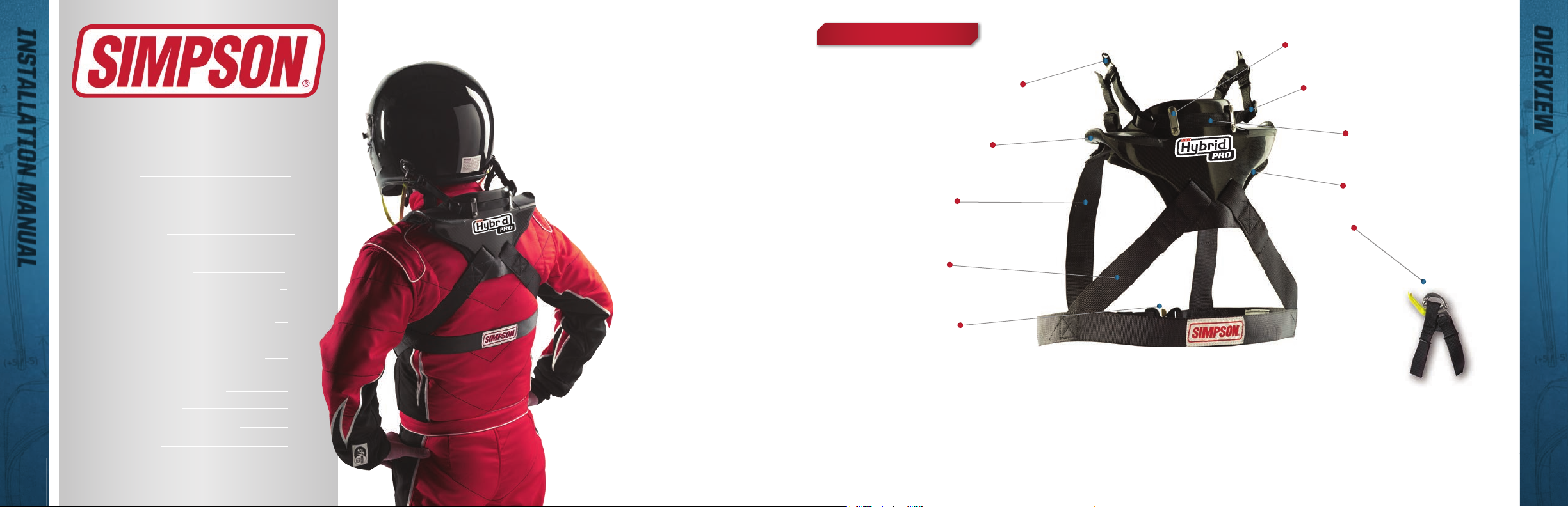
SIMPSON HEAD RESTRAINT
TIE PLATES
You’re ready to use the technology that protects the
world’s top drivers. Here are the steps to get started.
Overview 3
Anchor Installation 4
Fitting the Restraint 7
Seat Positions 7
In Car Adjustments
Tether Adjustment 8
Side Stabilizing Gusset Adjustment 10
Seat Belt Positioning
Restraint System Mounting Zones 11
Optional Accessories
Seat belt Anchor Systems (SAS) 12
Hybrid Molded Pad 13
Helmet Tethers and Clips 14
Helmet Anchors 15
Frequently Asked Questions 16
Certifi cations 19
Questions? Call us at 800.654.7223
11
IT’S A SIMPSON.
Simpson Hybrid Head Restraints are the best
choice for racing protection.
HYBRID, HYBRID PRO and HYBRID SPORT
Head Restraints are SFI 38.1 Certifi ed
and FIA 8858-2010 Certifi ed. Designed
for easily exiting the car without
the danger of getting hung up
on other gear, our Head
Restraints also offer the
lowest profi le and highest
level of multiple angle
impact protection of
any competing device.
Plus, they provide you
with maximum comfort
and maneuverability. Expertly
engineered by Trevor Ashline
with Safety Solutions technology,
Simpson Head Restraints give you every
advantage on the track.
DUAL END FITTINGS
RUBBER SHOULDERS
SHOULDER STRAP
BACK STRAP
BUCKLE
The Simpson Hybrid head restraints series carries SFI 38.1 certifi cation; the Hybrid
and Hybrid Pro are NASCAR certifi ed, the Hybrid, Hybrid Pro, and Hybrid Sport are FIA
Approved. Our head restraints are recognized by most major sanctioning bodies across the
world. If you are unsure, check with your local sanctioning.
3-BAR
SLIDING TETHER
DEVICE PAD
QUICK RELEASE
(STANDARD on
SFI CERTIFIED
RESTRAINTS)
Figure 1
Hybrid Pro pictured with optional M6 upgrade
DRIVEN BY SAFETY TEAMSIMPSON.COM 3
Page 3
With the 2012 mandates in effect, the Simpson Hybrid Pro has endured stringent testing to
prove that it is the safest option on the market. As part of Simpson’s SFI 38.1 certifi ed line of
Head and Neck Restraints, it was designed with the lowest profi le for maximum comfort and
With the 2012 mandates in effect, the Simpson Hybrid Pro has endured stringent testing to
TAKING IMPACTS
MULTIPLE ANGLE IMPACTS ACTUALLY, AND A LOT OF THEM.
With the 2012 mandates in effect, the Simpson Hybrid Pro has endured stringent testing to
prove that it is the safest option on the market. As part of Simpson’s SFI 38.1 certifi ed line of
Head and Neck Restraints, it was designed with the lowest profi le for maximum comfort and
With the 2012 mandates in effect, the Simpson Hybrid Pro has endured stringent testing to
AND
MULTIPLE ANGLE IMPACTS ACTUALLY, AND A LOT OF THEM.
ANCHOR INSTALLATION
ANCHOR INSTALLATION INSTRUCTIONS
ANCHOR INSTALLATION
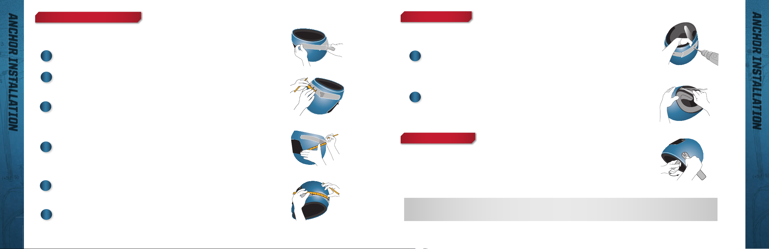
M6 AND POST ANCHORS
Initial Steps for Helmets without holes for tether anchors.
Apply masking tape around the bottom of your helmet approximately 1”
1
(26mm) up from the top edge of the rubber molding.
On the masking tape at the back of the helmet, mark three points 1.5” (43mm)
2
above the rubber molding and spaced about a half inch apart. Connect the
dots to create a horizontal line.
Using a fl exible ruler, measure the same distance from a fi xed point (for
3
example - the visor mounting hole) on each side of the helmet back to the
horizontal line. The center line of the helmet is midway between where the two
lines intersect the horizontal line at the back of the helmet.
4
Measure 6” (150mm) forward from the rear center line on each side of the
helmet to a point 1.5” (43mm) above the rubber molding.
Make sure you have two marks, each 6” forward from the rear center line a 1.5”
above the top edge of the rubber edge molding.
Slowly drill a 1/4” (6mm) hole at the two hole centers marked above. Drill
5
through the helmet shell but not through the soft padding. A thin piece of sheet
metal can be slipped between the shell and padding to help this.
De-burr and clean holes.
6
See Figure 3
See Figure 2
See Figure 4
See Figure 5
See Figure 6
Figure 2
Figure 3
Figure 4
Figure 5
Final Steps - Helmets without holes and pre-drilled helmets.
1
Gently pry helmet liner away from shell using a blunt instrument. See Figure 7
Insert the nutwasher inside the helmet against the shell using a wrench. Align
with hole. Insert post through the cap, spring and base and screw into nutwasher.
Tighten until the point of the post faces rearward.
Use a 7/16” (11mm) wrench to hold the post anchor outside of the helmet in
2
position and tighten from inside.
Tighten 1/4 turn beyond snug. The fl ats and slot of the post anchor should be
parallel with the ground and the point of the post should face the rear of the helmet.
QUICK RELEASE ANCHORS
Gently pry helmet away from shell using blunt instrument.
Insert the nutwasher inside the helmet against the shell using a wrench.
Align the hole. Screw anchor into nutwasher. Hand tighten until the tether or hasp
faces rearward. Use a 7/16” (11mm) wrench to hold the nutwasher inside the helmet
and tighten exterior screw 1/4 turn beyond snug.
SAFETY NOTE Simpson recommends using thread locking fl uid when assembling the M6 and helmet post anchors.
*REFER TO YOUR SANCTIONING RULES FOR HELMET INSTALLATION.
See Figure 8
Figure 6
Figure 7
See Figure 7
Figure 8
4 TEAMSIMPSON.COM TOLL FREE 800.654.7223
DRIVEN BY SAFETY TEAMSIMPSON.COM 5
Page 4
With the 2012 mandates in effect, the Simpson Hybrid Pro has endured stringent testing to
prove that it is the safest option on the market. As part of Simpson’s SFI 38.1 certifi ed line of
Head and Neck Restraints, it was designed with the lowest profi le for maximum comfort and
With the 2012 mandates in effect, the Simpson Hybrid Pro has endured stringent testing to
TAKING IMPACTS
MULTIPLE ANGLE IMPACTS ACTUALLY, AND A LOT OF THEM.
With the 2012 mandates in effect, the Simpson Hybrid Pro has endured stringent testing to
prove that it is the safest option on the market. As part of Simpson’s SFI 38.1 certifi ed line of
Head and Neck Restraints, it was designed with the lowest profi le for maximum comfort and
With the 2012 mandates in effect, the Simpson Hybrid Pro has endured stringent testing to
AND
MULTIPLE ANGLE IMPACTS ACTUALLY, AND A LOT OF THEM.
ANCHOR INSTALLATION
ANCHOR INSTALLATION INSTRUCTIONS
FITTING THE RESTRAINT / SEAT POSITION
FITTING THE RESTRAINT
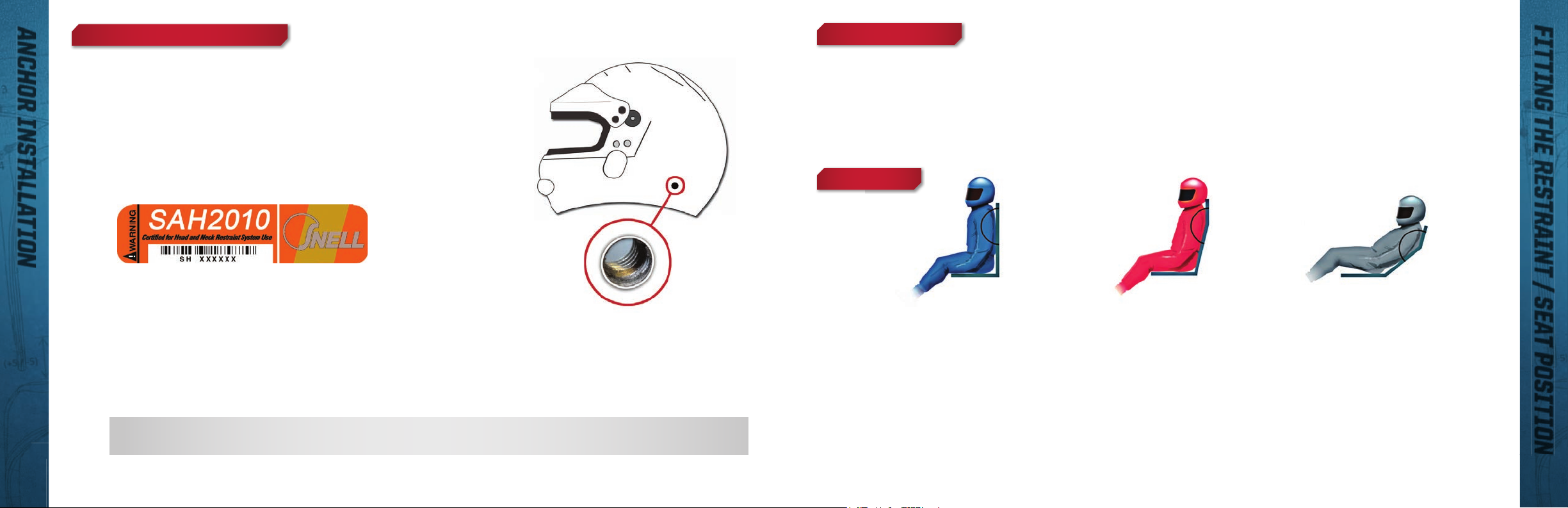
SAH2010 Helmets with Bonded-in Threaded Anchor Terminals
You may have purchased one of the newest helmets marked Snell
SAH2010. These helmets are certifi ed for head restraint system use.
Snell SAH2010 decal located inside the helmet
Helmets marked Snell SAH2010 have a bonded-in and threaded
terminal (nutwasher) making Simpson anchor installation easy. Screw
the anchor into the nutwasher. Hand tighten until the point on the collar
(if post anchor) or bail (if quick release) faces rearward. Tighten the
mounting screw 1/4 turn beyond snug.
SAFETY NOTE Simpson recommends using thread locking fl uid when assembling the M6 and helmet post anchors.
6 TEAMSIMPSON.COM TOLL FREE 800.654.7223
Figure 9
Bonded-in terminal
on sides of helmet
The Hybrid Head Restraint has an adjustable chest strap to fi t a variety of body types. Custom made restraints are also available. Call Team Simpson at 800-654-7223 for more information.
To adjust the chest strap: loosen the chest strap at the buckle and slide the buckle to fi t
the occupant’s chest size. Chest strap should fi t snug, but comfortable.
SEAT POSITIONS
0°-10° 10°- 30° 30°+
Figure 10 Figure 11 Figure 12
STRAIGHT
A completely smooth or fl at
back to the seat.
Typical applications are:
Sprint Cars, Pro Mods, Pro Stock,
Top Sportsman, Monster Truck
NOTE: Changing seat confi gurations may require tether adjustments.
CONTOURED
A 10-30 degree of change in the
seat at the shoulder blade area.
Typical applications are:
Late Models, GT-1, Pro Trucks,
Hydroplanes
LAYBACK
A 30 degree of more change in the
seat at the shoulder blade area.
Typical applications are:
Indy Cars, Nostalgia Dragsters
DRIVEN BY SAFETY TEAMSIMPSON.COM 7
Page 5

With the 2012 mandates in effect, the Simpson Hybrid Pro has endured stringent testing to
prove that it is the safest option on the market. As part of Simpson’s SFI 38.1 certifi ed line of
Head and Neck Restraints, it was designed with the lowest profi le for maximum comfort and
With the 2012 mandates in effect, the Simpson Hybrid Pro has endured stringent testing to
TAKING IMPACTS
MULTIPLE ANGLE IMPACTS ACTUALLY, AND A LOT OF THEM.
With the 2012 mandates in effect, the Simpson Hybrid Pro has endured stringent testing to
prove that it is the safest option on the market. As part of Simpson’s SFI 38.1 certifi ed line of
Head and Neck Restraints, it was designed with the lowest profi le for maximum comfort and
With the 2012 mandates in effect, the Simpson Hybrid Pro has endured stringent testing to
AND
MULTIPLE ANGLE IMPACTS ACTUALLY, AND A LOT OF THEM.
IN CAR ADJUSTMENTS
IN CAR HELMET TETHER ADJUSTMENT
RESTRAINT TETHERS
1
2
3
Helmet Tethers MUST be adjusted for proper fi t before use.
Helmet tether adjustment needs to be made with the driver seated and buckled into the vehicle with full gear
including, suit, helmet, and seatbelt harnesses.
Get into car and buckle fully into the seat with seat belts. The head restraint
should fi t comfortably under the shoulder harnesses.
Seat the restraint against the shoulder belts by pulling up on the helmet
tethers, before they are hooked to the helmet. The device will rest against the
shoulder belts on the top, the seat in back and the driver’s shoulders.
The helmet tethers should be adjusted or changed to allow for no more than
2.25” of straight forward head movement. Measure from a resting position
(See Figure 13 dotted line) moving your entire head forward (not your chin to
your chest). You should still be able to rotate your chin to your chest.
no more than 2.25” of straight
forward movement
ADJUSTABLE (SFI) TETHRS
Adjust the rear helmet tether fi rst; they are the PRIMARY RESTRAINT The tethers are easily
4
adjusted by unlacing the tether webbing through the 3-bar adjuster and lengthening or shortening
the tethers through the 3-bar adjustments.
The forward helmet movement can be checked by measuring the amount of forward movement as
5
the driver moves their head straight forward, with the chin up.
The tether adjustment is the measurement when the tethers fi rst have tension.
6
When the rear tether adjustments are complete make sure to lock down the tether by weaving
7
the webbing back through the adjuster one last time. Use the rubber O-ring to hold the excess
webbing in place.
IN CAR ADJUSTMENTS
8 TEAMSIMPSON.COM TOLL FREE 800.654.7223
Figure 13
DRIVEN BY SAFETY TEAMSIMPSON.COM 9
Page 6

With the 2012 mandates in effect, the Simpson Hybrid Pro has endured stringent testing to
prove that it is the safest option on the market. As part of Simpson’s SFI 38.1 certifi ed line of
Head and Neck Restraints, it was designed with the lowest profi le for maximum comfort and
With the 2012 mandates in effect, the Simpson Hybrid Pro has endured stringent testing to
TAKING IMPACTS
MULTIPLE ANGLE IMPACTS ACTUALLY, AND A LOT OF THEM.
With the 2012 mandates in effect, the Simpson Hybrid Pro has endured stringent testing to
prove that it is the safest option on the market. As part of Simpson’s SFI 38.1 certifi ed line of
Head and Neck Restraints, it was designed with the lowest profi le for maximum comfort and
With the 2012 mandates in effect, the Simpson Hybrid Pro has endured stringent testing to
AND
MULTIPLE ANGLE IMPACTS ACTUALLY, AND A LOT OF THEM.
o o
o o
IN CAR ADJUSTMENTS
SIDE STABILIZING GUSSET (SSG) ADJUSTMENT
RESTRAINT SYSTEM MOUNTING ZONES
RESTRAINT SYSTEM MOUNTING ZONES
9
Unhook the tether from the helmet.
Hold the SSG up to the Helmet Anchor.
10
Adjust the length of the tether to the bottom of the Helmet Anchor
11
with the driver in their normal position looking straight forward.
NOTE: Some drivers may want this tether shortened for
more side to side restriction. The tether may be adjusted
shorter by as much as 1” depending on driver comfort.
With this adjustment too short, the helmet will be pulled
downward on the driver’s head and may be
uncomfortable.
12
Tethers adjusted properly should create a “Triangle” in the tether
adjustment.
10 TEAMSIMPSON.COM TOLL FREE 800.654.7223
See Figure 14
Figure 14
The shoulder belts should be mounted as close to the occupant as possible,
separated by 2-3 inches between the inside edges of the belts.
CRISSCROSS
BELT POSITION
Figure 15
Figure 16
SEPARATED
BELT POSITION
Recommended distance between the
inside edges of the belts is 2” - 3”.
DRIVEN BY SAFETY TEAMSIMPSON.COM 11
Figure 17
Page 7

With the 2012 mandates in effect, the Simpson Hybrid Pro has endured stringent testing to
prove that it is the safest option on the market. As part of Simpson’s SFI 38.1 certifi ed line of
Head and Neck Restraints, it was designed with the lowest profi le for maximum comfort and
With the 2012 mandates in effect, the Simpson Hybrid Pro has endured stringent testing to
TAKING IMPACTS
MULTIPLE ANGLE IMPACTS ACTUALLY, AND A LOT OF THEM.
With the 2012 mandates in effect, the Simpson Hybrid Pro has endured stringent testing to
prove that it is the safest option on the market. As part of Simpson’s SFI 38.1 certifi ed line of
Head and Neck Restraints, it was designed with the lowest profi le for maximum comfort and
With the 2012 mandates in effect, the Simpson Hybrid Pro has endured stringent testing to
AND
MULTIPLE ANGLE IMPACTS ACTUALLY, AND A LOT OF THEM.
OPTIONAL SEAT BELT ANCHOR SYSTEM
OPTIONAL HYBRID MOLDED PAD
OPTIONAL HYBRID MOLDED PAD
OPTIONAL HYBRID MOLDED PADOPTIONAL SEAT BELT ANCHOR SYSTEM (SAS)
The SAS straps need to attach to the seat belt buckle; the
SAS is an additional load path for the restraint allowing for
stabilization of the driver.
Camlock Attachment Slide each SAS O-ring onto two of
the camlock buckle tongues.
Latch-in-Link Attachment Pair the SAS O-rings and slide
them into the latch link shoulder belts or the fi ve point
depending on your set-up.
The SAS straps should be adjusted to be snug when the
buckle is latched with no more than 2 fi ngers of room.
Adjustment is made by sliding the 1” webbing attached to
the loops through the 3-bar adjuster.
OPTIONAL SAS LOOPS AVAILABLE
Figure 20 Figure 21
12 TEAMSIMPSON.COM TOLL FREE 800.654.7223
See Figure 18
See Figure 19
Figure 18
Figure 19
The Hybrid Optional Molded Pad is placed
behind the driver between the seat and the
driver’s back and shoulders.
The U-Shaped Molded Pad can be cut, and/or
trimmed to fi t driver’s seat. Tape, glue, or Velcro
the molded pad in place depending on type of
seat. If the seat has a cover, the pad can be
installed under the cover.
The Pad is inserted into the seat back. When
the driver sits back, the device nests into the
voided area creating one smooth surface behind
the driver’s back. The wings of the restraint
should extend under the shoulder belts between
the seat back and the driver.
Figure 22
DRIVEN BY SAFETY TEAMSIMPSON.COM 13
Page 8

With the 2012 mandates in effect, the Simpson Hybrid Pro has endured stringent testing to
prove that it is the safest option on the market. As part of Simpson’s SFI 38.1 certifi ed line of
Head and Neck Restraints, it was designed with the lowest profi le for maximum comfort and
With the 2012 mandates in effect, the Simpson Hybrid Pro has endured stringent testing to
TAKING IMPACTS
MULTIPLE ANGLE IMPACTS ACTUALLY, AND A LOT OF THEM.
With the 2012 mandates in effect, the Simpson Hybrid Pro has endured stringent testing to
prove that it is the safest option on the market. As part of Simpson’s SFI 38.1 certifi ed line of
Head and Neck Restraints, it was designed with the lowest profi le for maximum comfort and
With the 2012 mandates in effect, the Simpson Hybrid Pro has endured stringent testing to
AND
MULTIPLE ANGLE IMPACTS ACTUALLY, AND A LOT OF THEM.
OPTIONAL TETHERS, ANCHORS & CLIPS
OPTIONAL HELMET TETHERS
OPTIONAL TETHERS, ANCHORS & CLIPS
OPTIONAL HELMET ANCHORS
QUICK RELEASE TETHERS
USED WITH D-RING (STANDARD)
M61 DUAL END FITTING TETHER
USED WITH M6 ANCHOR SYSTEM
14 TEAMSIMPSON.COM TOLL FREE 800.654.7223
HYBRID QUICK CLICK TETHERS
EZ SLIDE DUAL END FITTING TETHER
AVAILABLE WITH QUICK RELEASE OPTION
EZ SLIDE LOOPS
USED WITH SIMPSON QUICK CLICKS
HYBRID POST CLIPS
USED WITH SIMPSON POST ANCHORS
M6 ANCHOR
WITH DUAL END FITTING
SIMPSON QUICK CLICK SYSTEM
DRIVEN BY SAFETY TEAMSIMPSON.COM 15
SIMPSON POST ANCHORS
QUICK RELEASE ANCHORS
Page 9

With the 2012 mandates in effect, the Simpson Hybrid Pro has endured stringent testing to
prove that it is the safest option on the market. As part of Simpson’s SFI 38.1 certifi ed line of
Head and Neck Restraints, it was designed with the lowest profi le for maximum comfort and
With the 2012 mandates in effect, the Simpson Hybrid Pro has endured stringent testing to
TAKING IMPACTS
MULTIPLE ANGLE IMPACTS ACTUALLY, AND A LOT OF THEM.
With the 2012 mandates in effect, the Simpson Hybrid Pro has endured stringent testing to
prove that it is the safest option on the market. As part of Simpson’s SFI 38.1 certifi ed line of
Head and Neck Restraints, it was designed with the lowest profi le for maximum comfort and
With the 2012 mandates in effect, the Simpson Hybrid Pro has endured stringent testing to
AND
MULTIPLE ANGLE IMPACTS ACTUALLY, AND A LOT OF THEM.
FREQUENTLY ASKED QUESTIONS
FAQS
FREQUENTLY ASKED QUESTIONS
FAQS
Q: My Helmet came pre-drilled, can I use the pre-drilled hole?
A: Simpson helmets will be the correct location. If your helmet is not a Simpson check with your helmet
manufacturer to confi rm the location.
Q: Do I need special seat belts to work with your devices?
A: No, our devices work with 2 or 3 inch seat belts, Latch and Link or Cam Lock.
Q: Do I need to replace my head restraint if I am involved in a wreck?
A: Your Simpson Head Restraint device is built to sustain the most violent of wrecks. However, in the event
of a hard wreck, you should send your restraint to us for proper inspection by a Simpson Safety Specialist.
We may recommend replacing the helmet tethers. While the chances of the device being unharmed are great,
it is not worth taking a chance.
Q: Can two people of different sizes share the same device?
A: Yes, we have a chest extender that will plug into the chest strap to give more length in the chest.
Q: Is my device adjusted wrong if I can touch my chin to my chest?
A: No, with your device adjusted correctly you should be able to rotate you head enough for your chin to
touch your chest.
Q: I am having trouble turning my head even after adjustments, what should I do?
A: Call you Simpson Safety Specialist; your setup may require an EZ Slide System.
Q: When I measure my helmet for the anchors hard foam in the way on the inside, what should I do?
A: Very gently use a large fl at screw driver or small pry bar to wedge between the liner and the shell.
This liner is not glued into the helmet, but use caution not to compromise the shell or the liner. Then
simply slide the nut washer into place. DO NOT DRILL THROUGH OR COMPROMISE THIS FOAM LINER.
Q: I have a Hybrid and it feels like it pushes me forward out of the seat. What can I do?
A: You can order the optional molded seat pad that can be cut, trimmed, shaved or ground to be
whatever shape you need to be comfortable.
Q: My child is just getting started racing, will I have to purchase another device as they grow?
A: Probably not. This will depend on how big they are and how fast they grow. Once the child is at a 28
inch chest, the device that they wear will be able to be re-sized to whatever size they need.
Q: How often should I replace my head restraint?
A: Each Sanctioning body is different. As of 2012 SFI required all SFI 38.1 certifi ed devices to be
inspected every 5 years. For additional information on recertifi cation please check out our web site at
www.teamsimpson.com
16 TEAMSIMPSON.COM TOLL FREE 800.654.7223
DRIVEN BY SAFETY TEAMSIMPSON.COM 17
Page 10

With the 2012 mandates in effect, the Simpson Hybrid Pro has endured stringent testing to
prove that it is the safest option on the market. As part of Simpson’s SFI 38.1 certifi ed line of
Head and Neck Restraints, it was designed with the lowest profi le for maximum comfort and
With the 2012 mandates in effect, the Simpson Hybrid Pro has endured stringent testing to
TAKING IMPACTS
MULTIPLE ANGLE IMPACTS ACTUALLY, AND A LOT OF THEM.
With the 2012 mandates in effect, the Simpson Hybrid Pro has endured stringent testing to
prove that it is the safest option on the market. As part of Simpson’s SFI 38.1 certifi ed line of
Head and Neck Restraints, it was designed with the lowest profi le for maximum comfort and
With the 2012 mandates in effect, the Simpson Hybrid Pro has endured stringent testing to
AND
MULTIPLE ANGLE IMPACTS ACTUALLY, AND A LOT OF THEM.
DISCLAIMER
DISCLAIMER
Vehicle racing is inherently a dangerous sport with signifi cant risk of person injury or even death. When a user participates in vehicle racing, he accepts the risk inherent therein.
Simpson Performance, Inc. makes no warranty that the use of its products or parts guarantees personal safety or freedom from physical injury or operates as a life saving device.
SIMPSON PERFORMANCE, INC.’S PRODUCTS AND PARTS ARE SOLD “AS IS” WITHOUT ANY WARRANTY WHATSOEVER. EXPRESS WARRANTIES, IMPLIED WARRANTIES,
WARRANTIES OF MERCHANTABILITY AND WARRANTIES OF FITNESS FOR A PARTICULAR PURPOSE ARE EXCLUDED. THE ENTIRE RISK OF QUALITY AND PERFORMANCE OF
SUCH PRODUCTS AND PARTS IS WITH THE BUYER, USER SUBSEQUENT USER, OR AGENT THEREOF (HEREIN “USER”). SHOULD SUCH PRODUCTS OR PARTS PROVE DEFECTIVE
FOLLOWING THEIR PURCHASE, THE BUYER AND NOT THE MANUFACTURE(S), DISTRIBUTOR(S), OR RETAILER(S), ASSUME THE ENTIRE COST OF ALL NECESSARY SERVICES OR
REPAIR.
Simpson Performance, Inc. disclaims all liability for any special, direct, incidental or consequential damages, or any damages whatsoever, including, without limitation, the loss of
life or limb, or damages due to bodily or personal injury, which may arise or result from the sale, installation, or use of any of its products and parts.
It is the user’s responsibility to inspect and verify the dimensions, specifi cations, and performance of all products and parts as being appropriate for the use to which the user will
put them prior to any actual installation and/or use of said products and parts.
Simpson Performance, Inc.’s products and parts are to be inspected by the user before each use for evidence of damage, defect, or wear. Any deviation by the user from the
manufacturer’s specifi cations concerning use, maintenance, repair, alterations and modifi cations constitutes willful negligence.
The installation of Simpson Performance, Inc.’s products or parts may adversely affect other vehicle components, safety equipment or manufactured goods (collectively “goods”).
Simpson Performance, Inc. assumes no responsibility for any damage to other goods, or bodily injury that may arise due to failure of other goods, due to installation and/or use,
either proper or improper, of its products or parts.
The liability of Simpson Performance, Inc. is limited to the replacement of defective products or parts found under examination by manufacturer to be defective in material or
workmanship within 60 days after purchase, and which has not been caused by an accident, improper use, alteration, tampering, excessive use, misuse, modifi cation or abuse.
The damage of the user shall be deemed liquidated in the costs of replacement of the product or part.
Simpson Performance, Inc. assumes no responsibility for errors, omissions, diagrams, pictures, illustrations or text in these instructions or the documents contained herewith.
By purchasing or using this product, the user agrees that if any provision of this Disclaimer is held to be illegal, invalid or unenforceable under present or future law, such provision
shall be fully severed from the Disclaimer and this Disclaimer shall be construed and enforced as if such illegal, invalid or unenforceable provision never comprised a part
hereof, and the remaining provisions hereof shall remain in full force and effect and shall not be affected by the illegal, invalid, or unenforceable provision, there shall be added
automatically as part of this Disclaimer a provision as similar in its terms to such illegal, invalid or unenforceable provision as may be possible and be legal, valid and enforceable.
CERTIFICATIONS
CERTIFICATIONS
SINCE 1959, SIMPSON PERFORMANCE PRODUCTS has been the leading manufacturer of safety equipment for the
Motorsports Industry. We believe in putting safety fi rst and are dedicated to elevating the standards of racing safety
through continuous development, refi nement and testing as well as a strong partnership with racing sanctioning
bodies worldwide. The Hybrid Head Restraints are certifi ed by SFI and FIA.
SFI: THE SFI FOUNDATION, INC is a non-profi t organization established to issue and administrate safety standards
for specialty and performance of automotive and racing equipment. SFI Oversees testing and standards for fi re suits,
restraints and many other high performance safety products in the United States. NASCAR and NHRA are among the
sanctioning bodies who abide by SFO standards.
MORE INFORMATION CAN BE FOUND AT WWW.SFIFOUNDATION.COM
FIA: THE FEDERATION INTERNATIONALE DE L’AUTOMOBILE is a non-profi t organization that brings together
227 national motoring and sporting organizations from 132 countries on fi ve continents. FIA Formula One World
Championship, FIA World Rally Championship and FIA World Touring Car Championship are among the sanctioning
bodies who abide by FIA standards.
MORE INFORMATION CAN BE FOUND AT WWW.FIA.COM
MODEL # SERIAL #
18 TEAMSIMPSON.COM TOLL FREE 800.654.7223
The products and parts shown herein are to be installed and used adjusted in accordance with these instructions. Any deviation by the buyer,
installer, or user from these instructions constitutes willful negligence. Products and parts are not to be used if defective, damaged or worn.
Products and parts are not to be used after a severe use, in any event.
DRIVEN BY SAFETY TEAMSIMPSON.COM 19
Page 11

DRIVEN BY
SAFETY
CALL CUSTOMER SERVICE TOLL FREE 800.654.7223
OR E-MAIL SALES SALES@TEAMSIMPSON.COM
VISIT TEAMSIMPSON.COM
DRIVEN BY SAFETY TEAMSIMPSON.COM 20
 Loading...