

Page 1
Simpson Model 886-2
Sound Level Meter
OPERATOR’S MANUAL
Page 2

About this Manual
To the best of our knowledge and at the time written, the information contained in
this document is technically correct and the procedures accurate and adequate
to operate this instrument in compliance with its original advertised specifications.
Notes and Safety Information
This Operator’s Manual contains warning symbols which alert the user to check
for hazardous conditions. These appear throughout this manual where applicable, and are defined below. To ensure the safety of operating performance of
this instrument, these instructions must be adhered to.
Warning, refer to accompanying documents.
!
Caution, risk of electric shock.
!
This instrument is designed to prevent accidental shock to the operator when
properly used. However, no engineering design can render safe an instrument
which is used carelessly. Therefore, this manual must be read carefully and completely before making any measurements. Failure to follow directions can result
in a serious or fatal accident.
Technical Assistance
SIMPSON ELECTRIC COMPANY offers assistance Monday through Friday
8:00 am to 4:30 pm Central Time. To receive assistance contact Technical Support or Customer Service at (715) 588-3311.
Internet: http://www.simpsonelectric.com
Warranty and Returns
SIMPSON ELECTRIC COMPANY warrants each instrument and other articles
manufactured by it to be free from defects in material and workmanship under
normal use and service, its obligation under this warranty being limited to making
good at its factory or other article of equipment which shall within one (1) year
after delivery of such instrument or other article of equipment to the original
purchaser be returned intact to it, or to one of its authorized service centers, with
transportation charges prepaid, and which its examination shall disclose to its
satisfaction to have been thus defective; this warranty being expressly in lieu of
all other warranties expressed or implied and of all other obligations or liabilities
on its part, and SIMPSON ELECTRIC COMPANY neither assumes nor authorizes any other persons to assume for it any other liability in connection with the
sales of its products.
This warranty shall not apply to any instrument or other article of equipment
which shall have been repaired or altered outside the SIMPSON ELECTRIC
COMPANY factory or authorized service centers, nor which has been subject to
misuse, negligence or accident, incorrect wiring by others, or installation or use
not in accord with instructions furnished by the manufacturer.
2
Page 3

NOTES
3
Page 4

Contents
1. INTRODUCTION .................................................................................. 7
1.1 General Description ........................................................................... 7
1.2 Specifications ..................................................................................... 7
1.3 Items Furnished With The Instrument ................................................. 9
1.4 Available Accessories ........................................................................ 9
2. INSTALLATION ................................................................................ 10
2.1 Unpacking And Inspection ...............................................................10
2.2 Shipping ........................................................................................... 10
2.3 Service ..............................................................................................10
2.4 Battery Installation Or Replacement ................................................ 10
2.5 Installation ........................................................................................10
2.5.1 Tripod or Strap Mounting .................................................................. 10
2.5.2 Remote Microphone Mounting ......................................................... 10
2.6 Care ..................................................................................................11
3. APPLICATION ................................................................................. 11
3.1 Decibel Scale ...................................................................................11
3.2 Measurement And Exposure Standards ..........................................11
3.3 Sound Fields ....................................................................................13
3.3.1 Free Field.......................................................................................... 13
3.3.2 Reverberant Field............................................................................. 13
3.3.3 Semi-Reverberant Field ................................................................... 13
3.4 Microphone Orientation .................................................................... 13
3.5 Effect Of Operator’s Presence .......................................................... 14
3.6 Windscreen ....................................................................................... 14
3.7 Meter Fluctuations ............................................................................ 15
3.8 Selecting A Weighting Characteristic ............................................... 15
3.9 Impact Noise .....................................................................................15
3.10 Background Noise ............................................................................ 16
3.11 Dual Sound Sources ........................................................................ 16
4. OPERATING INSTRUCTIONS ......................................................... 16
4.1 Precautions ....................................................................................... 17
4.2 Operational Items And Features ......................................................17
4.3 Sound Level Measurements ............................................................19
4.4 Use With Auxiliary Equipment ..........................................................20
4
Page 5

NOTES
5
Page 6

NOTES
6
Page 7

1. INTRODUCTION
1.1 General Description
The Simpson 886-2 Sound Level Meter (hereafter referred to as the 886-2 or the
Instrument) is a portable, general purpose sound level instrument, capable of
accurate sound level measurements over a range of 40 to 140 dB. This encompasses the noise level of a quiet residence to that beyond the threshold of pain.
This dB range is compatible with current Federal, State, and local noise ordinance requirements; including safety and environmental noise checks.
The 886-2 meets the requirements of the American National Standards Institute
(ANSI) Standard Specification S1.4 - 1983 for “Type 2 General Purpose Sound
Level Meters and the International Electro-Technical Commission (IEC) 651.” It
can be used by industry to measure noise levels to comply with Occupational
Safety and Health Act of 1970 (OSHA) and the Walsh-Healy Act, except for direct
measurement of impact (impulse) noise.
The 886-2 can be hand-held for rapid testing or mounted on a tripod for measurements over extended periods of time. The microphone is detachable and can be
extended from its case by use of an optional 25-foot microphone extension cable.
The meter case is constructed of high-impact molded plastic, especially contoured at the microphone end to minimize reflections of the sound energy field
being measured.
The 886-2 is equipped with a range selector switch which references the 0 dB
point of the indicating instrument to the range selected. For example, when the
range switch is set to 70, the zero (0) mark on the black arc is equal to 70 dB.
Push-button switches provide quick, direct selection of “A”, “B” or “C” weighting
networks and a battery check function. Fast or slow meter response is switch
selectable.
The 886-2 offers three outputs which are proportional to the sound level input; a
RMS output, a dB output, and an external filter output that is compatible with the
Simpson 898 Octave Band Filter.
1.2 Specifications
The specifications for the 886-2 are listed in Table 1-1.
1. Microphone: The microphone is a condenser type with the size
2. Sound Level: Measurement Ranges: 40 dB to 140 dB. Zero (0)
3. Accuracy: Meets ANSI S1.4 - 1983 for a Type 2 instrument.
4. Weighting: Three selectable networks modify overall fre-
Table 1-1. Specifications
as type L per ANSI S1.12 - 1967. The nominal
electrical impedance is 350 ⍀, 20% @ 23°C. The
microphone is omnidirectional; its angle of incidence which approximates random incidence
response is 70°.
dB reference is 20 μPascals. Maximum SPL: 140
dB SPL for linearity within 1 dB.
quency response to meet the ANSI specification
for the A, B, or C weighting curves for a Type 2
instrument. The “External Filter” jack may be used
to obtain a flat response.
7
Page 8

5. Meter: Pivot and Jewel movement with 2-1/2” dial
having end markings of -10 dB and +10 dB, and
fifteen 1 dB scale markings. From -5 dB to +10 dB
the accuracy and scale markings comply with the
ANSI specification for a Type 2 instrument.
6. Speed of Response: Types of response: Selectable “Slow” or “Fast” response times meet the exponential-time-averaging characteristic required by the ANSI specification for a Type 2 instrument.
SLOW Response: Response to a 500 millisecond tone burst of 1000
Hz is nominally 2.5 dB down from a reference
steady state signal at the same level and frequency. Overshoot response to a suddenly applied steady state signal is less than 0.5 dB. When
an applied signal is turned off, the decay rate is
less than 3 seconds per 10 dB.
FAST Response: Response to a 200 millisecond tone burst of 1000
Hz is nominally 2.0 dB down from a reference
steady state signal at the same level and frequency. Overshoot response to a suddenly applied steady state signal is less than 0.5 dB. When
an applied signal is turned off, the decay rate is
less than 0.5 seconds per 10 dB.
7. Linearity: Primary indicator range is from 0 dB to +10 dB on
each range. Overall indicator range is -5 dB to
+10 dB. The dedicated “OSHA” range primary
indication is +105 dB to +115 dB, with an overall
indication of +100 dB to +115 dB. Within these
limits, the primary indicator accuracy is .1 dB and
the overall accuracy is 1.5 dB.
8. Calibration: Recommended calibration frequency is 1000 Hz
at sound pressure levels of either 94 dB on the 90
dB range, or 114 dB on the 110 dB range. Calibration is screwdriver adjustable from side of case.
9. Output Connections: This Instrument is equipped with three outputs:
External Filter, RMS Output, and dB Output.
External Filter: Provides non-weighted (flat response) output of
120 mV RMS, at meter reading of +10 dB, into a
100 K⍀ load; a lower impedance may affect the
meter reading. This output is not affected by the
“Fast-Slow” setting. The recommended plug is
Switchcraft’s #750 (0.141" diameter).
RMS Output: Provides weighted or non-weighted output of 1.00
V RMS, at a meter reading of +10 dB, into a 100
K⍀ load; a lower impedance will not affect the
meter reading. This output is not affected by the
“Fast-Slow” setting. The recommended plug is
Switchcraft’s #850 (0.097" diameter).
8
Page 9

dB Output: Provides logarithmic output of +1.50 V DC, at a
meter reading of +10 dB, into a 100 K⍀ load; a
lower impedance will not affect the meter reading. The response time of this output is set by the
“Fast-Slow” setting. The exponential-time-averaging time constant is per ANSI S1.4 - 1983, paragraphs 6.2 and 6.3: Slow is 1000 milliseconds,
and Fast is 125 milliseconds. The recommended
plug is Switchcraft’s #850 (0.097" diameter).
10. Power Requirements: One 9-volt alkaline battery, NEDA 1604A (or
equal) will typically provide 40 hours of continuous operation.
11. Temperature Range:
Operating Temperature: -10°C to +50°C.
Storage Temperature: -40°C to +60°C with the battery removed.
12. Temperature influence: Typically 0.015 dB/°C at 1kHz.
13. Operating Humidity: 0 to 90% relative humidity (non-condensing) for
a reading change of < 0.5 dB.
14. Warm-up Time: Approx. 30 seconds.
1.3 Items Furnished With The Instrument
All items required to operate the 886-2 are furnished with each Instrument, and
are listed in Table 1-2.
Table 1-2.
Quantity Description Part Number
1 9-volt batteryNEDA 1604A*
1 Operator’s Manual 6-115308
*Available from local retail stores.
1.4 Available Accessories
Available accessories are listed in Table 1-3.
Table 1-3.
Description Part/Catalog Number
Screwdriver 5-116470
Windscreen 00197
Calibrator, 890-2 12890
Package Case 10-866065
Adapter, Microphone to Tripod 00184
Microphone Extension Cable 00198
Microphone Assembly 00183
898 Octave Band Filter Set 02231
9
Page 10

2. INSTALLATION
This section contains information and instructions for the packaging and shipping of the 886-2. Included are procedures for unpacking and inspection, service, shipping, battery installation, installation and care.
2.1 Unpacking And Inspection
Examine the shipping carton for obvious sign of damage. If shipping carton is in
good condition, inspect the Instrument for possible damage incurred during shipment. If damaged, notify the carrier and supplier and do not attempt further use of
the Instrument. If the Instrument appears to be in good condition, read Operator’s
Manual in its entirety. Become familiar with the Instrument as instructed in the
manual, then proceed to check the electrical performance as soon as possible.
2.2 Shipping
Pack the Instrument carefully and ship it prepaid to the proper destination. Insure
the Instrument. Save the shipping carton and packing materials for future storing
or shipping of the Instrument.
2.3 Service
This Instrument contains no operator serviceable parts, except for the battery.
Refer all service requests to the Simpson factory. If the Instrument is covered by
warranty, include the model number, serial number, and date of purchase.
2.4 Battery Installation Or Replacement
The 886-2 is powered by a 9-volt alkaline battery. The battery is packaged separately. To install or replace the battery:
a. Turn the range switch to the “OFF” position.
b. Using the screwdriver or coin, loosen the two screws located on the battery
cover access compartment and remove the cover.
c. Install or replace the battery with the connector on the left side of the Instru-
ment. Route the cable between the battery and upper wall of the battery
compartment.
2.5 Installation
The Instrument, when in operation, may be either hand-held or mounted on a
tripod. The physical position of the Instrument does not affect the accuracy.
2.5.1 Tripod or Strap Mounting
The 886-2 can be attached to any commercial, photography-type tripod having a
standard 1/4-20" mounting screw. The mounting screw is aligned with the threaded
insert in the case and finger-tightened. A camera-type carrying strap can be
attached to the threaded insert. Carry the Instrument with the strap around the
wrist to prevent accidental dropping.
2.5.2 Remote Microphone Mounting
A remote cable and microphone adapter can be used to mount the microphone to
10
Page 11

any commercial, photography-type tripod for remote operation of the microphone.
NOTE: The accuracy of a measurement will be affected by several factors, one of
which is the position of the microphone with respect to the sound source. Read
Section 3 carefully for general background information. (See Section 4 for operating instructions for obtaining correct data from the measurements
2.6 Care
a. Immediately clean any spilled materials from the Instrument and wipe dry. If
spillage is corrosive, use a suitable cleaner to remove it and to neutralize
corrosive action.
b. To protect the microphone, keep sharp objects away from the top. Never rest
the unit on the microphone. If the microphone is detached, always lay it on its
side.
c. Whenever the Instrument is not in use, set the range switch to the OFF posi-
tion.
d. Avoid prolonged exposure or usage in areas subject to temperature and
humidity extremes, vibration, mechanical shock, dust, corrosive fumes, and
strong electrostatic and electromagnetic interference.
e. Verify Instrument calibration with a 890-2 Acoustical Calibrator.
f. It is recommended that the Instrument be returned to factory annually (sooner
if required) for a complete overall check, adjustment, and calibration.
g. When the Instrument is not in use store it in a room free from temperature
extremes, dust, corrosive fumes, mechanical vibration and shock. If storage
time is expected to exceed 30 days, remove the battery.
3. APPLICATION
This section contains basic information required for effective application of the
886-2 Sound Level Meter, and must be understood before attempting to operate
the Instrument for the first time.
3.1 Decibel Scale
The human ear has a mid-frequency dynamic sound sensitivity range of greater
than one million to one, from the lowest level that can be detected to the highest
that can be tolerated without pain. Because of the large ratio of value involved, a
linear meter scale marked in pressure units becomes impractical. A scale based
on logarithms, called a decibel (dB) scale, is used. This scale expresses the ratio
between the sound pressure level being measured and a reference. This simplifies notation and manipulation by reducing large ratios into smaller convenient
numbers. For example, a million-to-one pressure ratio can be expressed on a 0
to 120 dB scale.
3.2 Measurement And Exposure Standards
The American National Standards Institute (ANSI), in collaboration with scientific
and engineering societies, has established a standard, S1.4-1983, for conformance of all approved sound level meters. Federal, state and local governments
11
Page 12
also have defined allowable noise (undesirable sound energy) level exposure
limits for persons in industrial environments. Selected and applicable parts of
those currently in force are cited in this manual. Standards and government
regulatory laws are subject to modification or expansion. Check for the latest
available documents and information.
+5
A
0
–5
C
B AND C
–10
–15
–20
–25
–30
–35
RELATIVE RESPONSE DECIBELS
–40
–45
–50
A
20 50 100
B
FREQUENCY RESPONSES
FOR SLM WEIGHTING
CHARACTERISTICS
200
500
FREQUENCY (Hz)
1000 2000
5000
10,000
20,000
Figure 3-1. A, B and C Weighted Responses of the Sound Level Meter
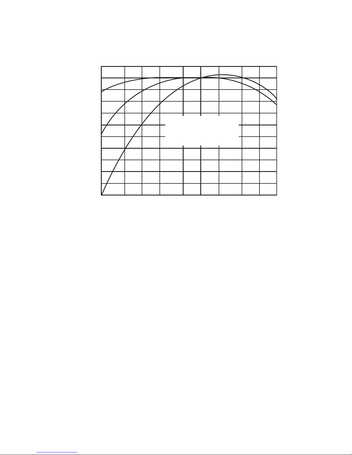
The specification for a Type 2 instrument takes into account the average response of the human ear which varies as a function of the intensity of sound. It
grounds intensity into three weighting curves; “A”, “B” and “C”. The “A” weighted
curve more closely corresponds to the human ear at the low sound levels.
As indicated in Figure 3-1, the “B” and “C” weighting curves include more of the
low frequency information. Thus, at any level, measurements taken with various
weightings can be compared in determining the frequency content of the noise.
This is done by indicating the level dB, accompanied by the weighting letter
notation “A”, “B” or “C”, preferable in parenthesis; e.g., the 100 dB (A), etc.
The allowable employee noise level exposure limits are established by the Occupational Safety and Health Act of 1970 (OSHA), the Walsh-Healy Act (Federal
Register, Volume 34, No. 96) and paragraph 1910.95 of the Occupational Safety
and Health Standards (Federal Register, Vol. 36, No. 105, May 29, 1971) and the
OSHA Hearing Conservation Program Amendment, Federal-Register Vol 46, No.
162, August 21, 1981. Table 3-1 summarizes these limits.
12
Page 13

*Table 3-1. Permissible Noise Exposure Limits
Duration per day in hours Sound level, dB(A) SLOW response
32 80
16 85
890
692
495
397
2 100
1-1/2 102
1 105
1/2 110
1/4 or less 115
*From Federal Register, Vol. 46, No. 162, August 21, 1981.
3.3 Sound Fields
3.3.1 Free Field
A free field contains no reflecting objects. Ideally it prevails around a point sound
source located in free space. However, it can be considered to exist whenever
the sound level being measured is caused mainly by sound waves coming directly from the sound source. This can occur even if there are reflecting objects,
if measurements are made close to the sound source.
3.3.2 Reverberant Field
A reverberant field contains reflecting objects and the sound level being measured is caused mainly by reflections of the sound source. This usually occurs at
a moderate distance from the sound source.
3.3.3 Semi-Reverberant Field
This field is encountered most commonly and exists whenever the sound level
being measured contains a significant amount of both reflected and direct sound
waves.
3.4 Microphone Orientation
a. When making measurements in a free or semi-reverberant field, orient the
microphone so that the angle of incidence, formed by incoming sound waves
and axis of the microphone, is equal to the random incidence angle of the
microphone. For the 886-2 this angle is 70° (refer to Figure 3-2).
b. When making measurements in a reverberant field, orientation of the micro-
phone is not critical. However, it is recommended, where possible, that the
operator use the same orientation (70°) as for the free or semi-reverberant
field.
c. Vertical orientation of the microphone is not critical except where it is in line
with a second sound source or a high-amplitude reflection of a sound source.
It usually is invalidated by a second sound source, or by a nearby reflecting
surface.
d. When evaluating a particular sound source, avoid holding the microphone
in such a way that the reading is invalidated by a second sound source, or by
the proximity of a nearby reflecting surface.
13
Page 14

3.5 Effect Of Operator’s Presence
When sound is coming mainly from one
direction, the reading might be affected
by the relative positions of the microphone
and operator. For example, if the operator and microphone are in line and facing
the sound source, there can be a marked
increase in response at high frequencies
because the operator will act as a reflector and produce errors of several dB at
frequencies above 100 Hz. A more uniform frequency response is obtained with
the Instrument extended as far as conveniently possible in front of the operator,
and the axis of the microphone oriented
to form an angle of incidence of 70° with
the incoming sound wave. Do not point
the Instrument toward a source of noise
other than the one being measured.
The 886-2 (or its microphone) can be
mounted on a tripod for further reduction
in the effects of the operator’s presence.
A practical arrangement is to tilt the microphone axis at an angle of approximately 45° to 70° with respect to the horizon. This allows the operator to step several feet back or completely away and
still be able to make measurements.
PLANE OF
MICROPHONE
SOUND SOURCE
ANGLE OF
INCIDENCE (70˚)
AXIS OF
MICROPHONE
INCOMING
SOUND WAVE
Top View
PLANE OF
MICROPHONE
AXIS OF
MICROPHONE
VERTICAL ANGLE
(45˚ – 70˚)
Side View
Figure 3-2. Orientation of
Microphone and Operator with
respect to incoming Sound Waves.
3.6 Windscreen
When making measurements where wind is present, a low frequency interference can be introduced by air passing across the microphone. Try to make
measurements where wind is not present; if this is not practical a windscreen
should be employed. When using this screen, indicated wind noise will be attenuated approximately 20 dB. The loss of system sensitivity occurring with use
of the windscreen is shown in Figure 3-3.
+5
+4
+3
+2
+1
0
–1
–2
–3
–4
FREQUENCY RESPONSE ERROR DUE TO WINDSCREEN (dB)
–5
200
500
1000
FREQUENCY (Hz)
2000
5000
10,000
Figure 3-3. Loss Of System Sensitivity Due To Windscreen
14
Page 15

NOTE: When making out-of-doors measurements, it is usually preferable to point
the microphone upward (to avoid interference from reflected high frequencies)
and as far from the body as is convenient.
Grease and dirt on the windscreen will affect sound level measurements. To
check for dirt or grease on the windscreen, measure the level of continuous noise
indoors with or without the windscreen in place. To clean the windscreen, wash
with a mild detergent. Thoroughly rinse and dry before placing over microphone.
3.7 Meter Fluctuations
If the meter indication fluctuates more than 3 dB, set the meter response switch of
the Instrument to the SLOW position unless otherwise specified in the applicable
specification. Then if the fluctuations are less than 6 dB, record a value of 3 dB
less than maximum indication. Infrequent, high peaks customarily are disregarded. (When making noise survey measurements record the highest peak.)
NOTE: As pointed out in Table 3-1, applicable standards require SLOW meter
response when making noise surveys.
3.8 Selecting A Weighting Characteristic
The weighting characteristic must be selected according to individual application
requirements. Noise codes and sound test procedures frequently specify the one
to be used. For example: “A” weighting often is employed for measurement of
speech interference by office and plant noise. Federal regulations such as the
Walsh-Healy Act require use of the “A” response for all tests. When a standard
test procedure is not involved, data can be taken with each of the three characteristics and thereby provide information on overall frequency content.
NOTE: If the weighting is not specified, common practice is to assume “A” weighting (ANSI S1.4-1983). Be sure to indicate the weighting used on all recorded
data.
3.9 Impact Noise
Impact (impulse) noise refers to noise impulses of less than 1 second duration,
occurring once or at intervals greater than 1 second, such as gunshots or drophammers. Impulse noise measurements are made with an impulse noise meter
such as the Simpson 899.
Impulse noise measurements can also be made using an oscilloscope and the
886-2. The oscilloscope is connected to the RMS output jack and calibrated,
using a steady sound source and correlating the scope deflection with the indication on the sound level meter.
A rough check of impulse noise having a duration greater than 5 milliseconds
can be made with a sound level meter. It is set on “C” weighting, “FAST” meter
response, and range switch in the 120 or 130 position. An indication of 125 dB is
approximately equivalent to an actual impulse noise of 140 dB (limit established
by the Walsh-Healy Act).
NOTE: Impulse noises having durations longer than 50 milliseconds and peak
levels of 140 dB will give readings higher than 125 dB. The Simpson 899 Impulse
Sound Level Meter may be used to take measurements such as these.
15
Page 16

3.10 Background Noise
Ideally, any sound source being measured should be isolated from effects due to
extraneous or background noise. If the background noise is 10 dB or more below
the sound source level desired, the effect from the background noise can be
considered negligible. In instances where the ratio is less than 10 dB, an approximation can be made using Figure 3-4 and measurements of the background
noise alone and the sound source with the background noise. Simply take the
difference between these measurements and locate this difference value of the
abscissa of Figure 3-4. Move in a vertical direction from this point to the intersect
of the curve and then horizontally to the corresponding ordinate point. This
ordinate point indicates a value to be subtracted from the total or sound source
with background noise measurement. The difference obtained represents the
sound source level. It should be noted that a difference of 3 dB or less between
sound source and background noise will provide only an indication of this sound
source level, not an accurate measurement.
3.11 Dual Sound Sources
When separate measurements are made on two sound sources, the combined
effect cannot be found by direct addition. For example: If two machines are
emitting equal noise levels of 80 dB, the combined level will be 83 dB, not 160 dB.
If the level of one source is 10 dB or greater than the other, then the lower level
source can be disregarded as it will be “masked” by the higher level source.
Information listed in Table 3-2 can be used for calculating the combined effect of
the two sources. If more than two sound levels are involved, combine the highest
two first, then combine the total with the next highest remaining sound level.
Continue this procedure until all noteworthy levels are combined.
Table 3-2. Combining Noise Sources
Difference Between No. Of dB to be Added to
Levels in dB Higher Level
0 3.0
2 2.1
4 1.5
6 1.0
8 0.6
10 0.4
4. OPERATING INSTRUCTIONS
This section contains instructions required for the operation of the 886-2 Sound
Level Meter. Follow these instructions carefully to obtain accurate and useful
data.
!
If noise levels exceed 115 dB(A) (SLOW response) immediate use of protective
ear muffs or plugs is required. According to the Occupational Safety and Health
16
Page 17

Act of 1970, noise that measures above 115 dB(A) is automatically “too high” for
any length of exposure approximately over one second.
10
9
8
7
6
5
4
3
2
1
0
dB CORRECTION (TO BE SUBTRACTED FROM TOTAL NOISE)
0
1
2
dB DIFFERENCE BETWEEN TOTAL NOISE &
BACKGROUND NOISE MEASUREMENTS
4
3
6 7
5
9
8
10
Figure 3-4. Background Noise Correction
4.1 Precautions
Read Section 3 before performing measurements. This section contains important information on terminology, standards, techniques, and precautions pertinent to sound and noise measurements.
Use the 890-2 Calibrator to check the calibration of the Sound Level Meter periodically, especially if the Instrument has been subjected to severe mechanical
shock or environmental extremes.
4.2 Operational Items And Features
All items and features used to operate the 886-2 are described in Table 4-1 and
illustrated in Figure 4-1.
Table 4-1. Operational Items And Features
1. Range Switch: This eleven position rotary switch is used to
turn the Instrument on and to select the desired measurement range. The range is indicated by the arrowhead. When the range
switch is set to the “OSHA” position, the dB
level is read on the red arc displaying the
OSHA range. With the range switch set to
one of the other dB ranges, the black arc is
used. A zero (0) indication on the black arc
17
Page 18

corresponds to either 130, 120, 110, 100, 90,
80, 70, 60, or 50 dB as determined by the
position of the range switch. An indication
other than zero (0) must be added to the range
selected to obtain final level indication. For
example, if the range switch is set to the 110
position, and the indication is +5, the sound
level is 115 dB.
2. A, B and C Weighting
Switches: These push-button switches are used to se-
lect the frequency response of the Instrument
in accordance with A, B and C weighting requirements of the ANSI Standard Specification for a Type 2 Sound Level Meter.
3. SLOW/FAST Slide
Switch: This slide switch is used to select the response
time of the meter circuit as defined in Table 1-1.
4. BATT TEST: A momentary push-button switch used to
check the condition of the battery.
5. Microphone: A condenser type microphone that converts
sound energy vibrations into electrical signals. Microphones are not interchangeable,
therefore, the Instrument must be recalibrated
Figure 4-1. Operational
Items And Features
5
7
6
2
4
9
A
(OSHA)
B
C
BATT
TEST
FAST
886-2
SOUND LEVEL METER
OFF
50
SLOW
O
SH
A
60
70
(OSHA)
TYPE S2A
130
12
0
100
110
0
9
80
8
1
3
Page 19

whenever the microphone is changed. The
microphone can be detached easily by first
pressing the microphone retaining latch.
6. Output Jacks:
Decibel Output Jack: A logarithmic output of 1.50 V DC is equiva-
lent to meter reading of +10 dB looking into
100 K⍀ load. The recommended plug for this
jack is a Switchcraft #850.
RMS Output Jack: A weighted or non-weighted output of 1.00 V
RMS is equivalent to a meter reading of +10
dB looking into a 100 K⍀ load. The recommended plug for this jack is a Switchcraft #850.
External Filter Jack: A non-weighted (flat response) output of 120
millivolts RMS is equivalent to a meter reading of +10 dB looking into 100 K⍀ load. The
recommended plug for this jack is a
Switchcraft #750.
7. Meter: A 0-100μA DC full scale, taut-band movement
with end markings of -10 dB and +10 dB and
1 dB divisions starting from -5 dB. The upper
end of the scale includes a BATT OK section.
8. Calibration Adjustment: This screwdriver adjustment, located under
a metal cap on the side of the Instrument, is
used to calibrate the 886-2. The Simpson
Model 890-2 Sound Level Calibrator, is designed to calibrate the 886-2. The calibration
procedures are contained in the operator’s
manual for the 890-2.
9. Battery Compartment: The battery compartment, which is totally
separated from the electronics, houses the
battery
4.3 Sound Level Measurements
To obtain sound level measurements with the 886-2.
a. Turn on the Instrument and select the desired measurement range. To en-
sure accurate results, check the battery every time sound level measure-
ments are made.
b. When the Instrument is hand-held, orientate the microphone approximately
45° to 70° with respect to the horizontal plane and at an angle of 70° with
respect to incoming sound waves.
c. For OSHA compliance measurement set FAST/SLOW switch to SLOW, the
range switch to OSHA, and depress “A” weighting push-button. Read exact
dB(A) on red OSHA arc.
d. For other applications, select the desired range, weighting, and response. If
the meter fluctuations are in excess of 3 dB set the response to SLOW posi-
tion.
NOTE: With the range switch set to any of the other ranges (black numerals), the
black indicator, and the switch position corresponds to zero (0) indication. For
example, if switch is set to 90, and the indication is 5, add 5 to 90 to obtain 95 dB
level.
e. To conduct impact noise checks, set FAST/SLOW switch to FAST, dB range
19
Page 20

switch to 120, and depress “C” weighting button. Check peak reading on
meter dial. A reading of 125 dB approximates an impulse noise of 140 dB,
which is the upper limit established by the Walsh-Healy Act.
f. When not in use return the range switch to the OFF position and store the
Sound Level Meter in a safe place.
4.4 Use With Auxiliary Equipment
The 886-2 is equipped with three outputs intended to be used with auxiliary
equipment such as a chart recorder, oscilloscope or the Simpson 898 Octave
Band Filter. These jacks are designed to give the operator more detailed and
comprehensive sound analysis study. The larger of the three jacks is designed to
be used with the Simpson 898 Octave Band filter. The operator’s manual for the
Model 898 describes how to use the 886-2 with this filter.
Non-Linear Distortion: When using “A” weighting at frequencies from 30 Hz to 50
Hz, the AC output will have observable distortion with levels exceeding 0 dB on
any meter range. For “B” and “C” weighting, the AC output remains linear at
levels up to +10 dB on any meter range and at any specification frequency.
20
Page 21

NOTES
21
Page 22

NOTES
22
Page 23

NOTES
23
Page 24

SIMPSON ELECTRIC COMPANY 520 Simpson Avenue
Lac du Flambeau, WI 54538-0099 (715) 588-3311 FAX (715) 588-3326
Printed in U.S.A. Part No. 06-115308 Edition 8, 05/07
Visit us on the web at: www.simpsonelectric.com
24
 Loading...