

Page 1
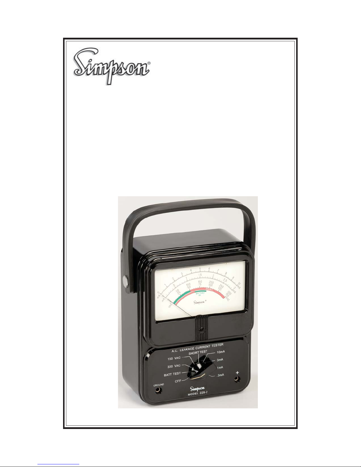
Model 229 Series 2
Leakage Current Tester
OPERATOR’S MANUAL
Page 2
About this Manual
To the best of our knowledge and at the time written, the information contained in this document is technically correct and the procedures accurate
and adequate to operate this instrument in compliance with its original advertised specifications.
Notes and Safety Information
This Operator’s Manual contains warning symbols which alert the user to
check for hazardous conditions. These appear throughout this manual where
applicable, and are defined below. To ensure the safety of operating performance of this instrument, these instructions must be adhered to.
Warning, refer to accompanying documents.
!
Caution, risk of electric shock.
!
This instrument is designed to prevent accidental shock to the operator when
properly used. However, no engineering design can render safe an instrument which is used carelessly. Therefore, this manual must be read carefully
and completely before making any measurements. Failure to follow directions can result in a serious or fatal accident.
Any discussion in this manual regarding UL, ANSI, or IEC specifications is for
Reference purposes only. The input network utilized in the M229 2 is detailed
in Figure 1 on page 3. The customer is advised to obtain the latest specification from the rating agency.
NOTE: For specification information call:
ANSI at (212) 642-4900 or UL in Northbrook, IL at (847) 272-8800.
Technical Assistance
SIMPSON ELECTRIC COMPANY offers assistance Monday through Friday
8:00 am to 4:30 pm Central Time. To receive assistance contact Technical
Support or Customer Service at (715) 588-3311.
Internet: http://www.simpsonelectric.com
Warranty and Returns
SIMPSON ELECTRIC COMPANY warrants each instrument and other articles manufactured by it to be free from defects in material and workmanship
under normal use and service, its obligation under this warranty being limited
to making good at its factory or other article of equipment which shall within
one (1) year after delivery of such instrument or other article of equipment to
the original purchaser be returned intact to it, or to one of its authorized
service centers, with transportation charges prepaid, and which its examination shall disclose to its satisfaction to have been thus defective; this warranty
2
Page 3

being expressly in lieu of all other warranties expressed or implied and of all
other obligations or liabilities on its part, and SIMPSON ELECTRIC COMPANY neither assumes nor authorizes any other persons to assume for it any
other liability in connection with the sales of its products.
This warranty shall not apply to any instrument or other article of equipment
which shall have been repaired or altered outside the SIMPSON ELECTRIC
COMPANY factory or authorized service centers, nor which has been subject
to misuse, negligence or accident, incorrect wiring by others, or installation or
use not in accord with instructions furnished by the manufacturer.
This manual represents your meter as manufactured at the time of publication.
We reserve the right to make changes and improvements to the product
without obligation to incorporate these changes and improvements into units
previously shipped.
SHOCK HAZARD: As defined in American National Standard, C39.5, Safety
Requirements for Electrical & Electronic Measuring & Controlling Instrumentation, a shock hazard shall be considered to exist at any part involving a
potential in excess of 30 volts RMS (sine wave) or 42.4 volts DC or peak and
where a leakage
current from that part to ground exceeds 0.5 milliampere,
when measured with an appropriate measuring instrument defined in Section 11.6.1 of ANSI C39.5.
NOTE: The proper measuring instrument for the measurement of leakage
current consists essentially of a network of a 1500 ohm non-inductive resistor
shunted by a 0.15 microfarad capacitor connected between the terminals of
the measuring instrument. The leakage current is that portion of the current
that flows through the resistor. The Simpson Model 229-Series 2 AC Leakage Current Tester is designed around the ANSI C39.5 requirement for the
measurement of AC leakage current. See Figure 1 below.
R3
+
INPUT
500
C1
0.15UF
R1
1000
Leakage Current Input Network
Figure 1
3
Page 4

Contents
1. INTRODUCTION .................................................................................. 5
1.1 Why Measure Leakage Current? ....................................................... 6
1.2 Threshold Of Perception .................................................................... 6
1.3 Technical Data ................................................................................... 6
1.4 Items And Accessories .......................................................................7
2. OPERATION ..................................................................................... 8
2.1 Safety Precautions ............................................................................. 8
2.3 Operating Instructions ........................................................................9
3. MAINTENANCE .............................................................................. 10
3.1 Warranty ...........................................................................................10
3.2 Shipping ...........................................................................................10
3.3 Battery Replacement ........................................................................ 10
3.4 Calibration ........................................................................................11
3.5 Care ..................................................................................................11
4
Page 5
1. INTRODUCTION
5
6
4
3
2
1
.5
00
1
0
5
50
25
B
Y
R
E
T
T
A
0
B
E
0
C
A
L
P
E
R
VAC
DESIGNED TO MEET USA STANDARD C101.1 FOR LEAKAGE CURRENT TESTERS
A.C. LEAKAGE CURRENT TESTER
150 VAC
SHORT TEST
300 VAC
OFF
MODEL 229-2
0
mA
GROUND
1
0
mA
BATT TEST
The Simpson Model 229-2 is a special purpose AC milliammeter designed to
measure hazardous leakage current from electrical appliances and other
power line operated equipment. A three-wire grounding power cord prevents
shock hazard by grounding the metal parts of the appliance; the grounding
connection, however, is subject to abuse and not always reliable or, sometimes, nonexistent or even defeated by the user (a two-wire extension cord,
for example). Leakage current is therefore measured with the grounding
connection open-circuited and is required to be within a specified limit for
shock prevention.
Leakage current (as it relates to a shock hazard), is the result of resistance
and capacitance between internal supply circuits and external parts accessible to an operator, which may flow through the operator’s body to an earth
ground and cause electric shock. Although the appliances are energized by
a 60 Hz power line circuit, some may have solid-state control circuits which
generate higher frequency currents and may contribute to the leakage current. The human body, however, has a decreasing sensitivity to the sensation
of electric shock as the frequency increases. The current ranges of the 2292 are compensated to indicate a decreasing value of current with an increase
in frequency in accordance with the perceptibility of the human body to shock.
The meter will have a constant indication for leakage current of 60 Hz and 20
kHz for the same degree of shock.
The 229-2 is designed only for measuring leakage current of appliances operating from 120 or 240 power line circuits. The current ranges of the 229-2 have
an insertion impedance of 1500 ohms, resistive with a parallel capacitance of
0.15
F. The meter indicates 1.1 times the average of the full-wave rectified
composite waveform of voltage across the 1500 ohm resistor. The 1500 resistance simulates the resistance of the human body and the capacitance compensates the meter indication to correspond with the decreasing sensitivity of
the body to shock at increasing frequency. See Figure 1 on page 3.
5
7
1.5
150
7
5
T
E
T
A
R
Y
OK
8
2
9
2.5
20
0
100
S
H
O
R
T
10mA
3mA
1mA
250
125
.3mA
10
mA
3
m
300
A
150
VAC
Page 6

The 229-2 is battery operated and completely insulated for user protection.
Solid-state circuitry permits a current sensitivity to be as high as 300
scale (minor divisions of 5
300V AC provide a convenient means of measuring the open circuit voltage
(between the accessible parts and ground) to determine whether leakage
current need be measured.
A). Two voltage ranges of 0-150V AC and 0-
1.1 Why Measure Leakage Current?
The primary purpose of measuring leakage current of electrically operated
equipment is to determine whether usage in a normal manner can present an
electrical safety hazard to the user. Leakage current may increase with use
and aging of the appliance and should be checked periodically to assure
continued safety to the user. Equipment with protective grounding through
the power cord is assumed to have faulty grounding connection at the outlet
when measuring leakage current. While the shock (see definition of shock
hazard on page 3 ) in itself might be slight from the standpoint of bodily harm,
the person, nevertheless might react violently out of surprise or fear, and may
cause injury to himself or someone else.
For a broad scope of leakage current measurements, the Simpson 229-2
covers the current measurement span from 5 microamperes to 10 milliamperes. The leakage current measurements can be made simply and dependably. The user can keep a record of potentially hazardous leakage
situations, and from data trends, be alerted to likely future failures. To evaluate the protection most meaningfully, one must test an electrical device or
appliance in accordance with the latest applicable national standards.
A full
1.2 Threshold Of Perception
Leakage current limits are based on the threshold of perception. The threshold of perception is the current level at which a particular person just perceives the flow of electrical current. A mean value of perception current equal
to 1.067 mA at 60 Hz was determined by tests performed on 28 men by
Charles F. Dalziel (see AIEE proceedings, Volume 69, 1950, Section 0184,
“Effect of Frequency on Perception Currents”). The threshold of perception of
some individuals tested was considerably less than 1.067 mA at 60 Hz.
1.3 Technical Data
Table 1. Technical Data
1. Function/Range: a) BATT. TEST
b) AC voltage (300V AC, and 150V AC)
c) SHORT TEST
d) AC current 10mA, 3mA, 1mA, and 0.3mA
2. Input Impedance On
Current Ranges: 1500
Figure 1
resistance shunted by 0.15 F. See
6
Page 7

3. Input Resistance On
Voltage Ranges 500K
1MEG
4. Accuracy @ 60 Hz,
Sine Wave: 3% on voltage and current ranges.
5. Frequency Response: Approximates Dalziel’s Percentile 50
(Current Ranges) Threshold of Perception Curve.
on the 150V VAC range
on the 300V VAC range
6. Reference Conditions: 23°C
7. Power Requirements: One 9-volt battery NEDA type 1604A
(Burgess Type PM-6 or equivalent).
8. Battery Life: Approximately 200 Hrs.
9. Rated Circuit-To- 300 Vrms
Ground Voltage:
10. Instrument Protection: The amplifier circuit and the meter are protected by signal clipping diodes at the amplifier input.
11. Overload Protection: The Instrument is capable of withstanding
momentary overloads up to 500 volts peak
(50/60 Hz) on all current and voltage ranges.
(See Section 2.3 Operating Instructions, #6.)
1°C, 30% to 60% relative humidity.
1.4 Items And Accessories
Table 2. Items Furnished With Instrument
Quantity .oN traPnoitpircseD
1 Test Lead Set — One red and one black, 00125
each 4 ft. long with combination probe tips
and removable insulated alligator clips at
one end and banana plugs on opposite end.
*1 9-volts batty, NEDA Type 1604A Alkaline Battery.
1O 511-5launaM s’rotarep705
*Batteries are standard item replaceable from local retail stores.
7
Page 8

2. OPERATION
!
The Model 229-2 is designed to prevent accidental shock when properly
used. However, no engineering design can make an Instrument safe when
used carelessly. Therefore, this manual must be read completely before
making any measurements. Failure to do so can result in a serious or fatal
accident.
This section of the manual contains information required to use and operate
the Model 229-2 in a safe and proper manner.
2.1 Safety Precautions
The Model 229-2 is designed to be used only by personnel qualified to recognize shock hazards and trained in the safety precautions required to avoid
possible injury. Refer to SHOCK HAZARD definition which is located on
page 3 of this manual.
1. Do not work alone when making measurements where a shock hazard
can exist. Notify a nearby person that you are intending to make such
measurements.
2. Remember, voltages might appear unexpectedly in defective equipment.
An open bleeder resistor can result in a capacitor’s retaining a dangerous charge. Remove all power and discharge all capacitors in the circuit
being measured before making connections or disconnections.
3. Locate all voltage sources and accessibility paths prior to making any
measurements or connections.
4. For your own safety, before each use, inspect the test leads, and connectors for cracks, breaks or crazes in the insulation. If defective, destroy and
replace immediately.
5. Hands, shoes, floor and workbench must be dry. Avoid measuring under
humid, damp or other environmental conditions that could affect the dielectric withstanding voltage of the test leads or the Instrument.
6. For maximum safety, do not
power is applied to the circuit being measured.
7. Do not use test leads which differ from those originally furnished with the
Instrument.
8. Do not float any measuring terminal more than the rated circuit to ground
voltage as specified in the Table 1, item 9.
touch test leads, circuit, or Instrument while
8
Page 9

2.3 Operating Instructions
!
Do not touch the device or appliance under test with power applied until
voltage and leakage current measurements have been made and found to be
within applicable requirements. Obviously, during the test the requisite electrical safety has not yet been established. Therefore when going through the
measurement procedure, do not touch test leads or device under test while
power is applied.
NOTE: Leakage current alone is not conclusive evidence of a shock hazard.
For safe operation, the open circuit voltage between the same two points
must not exceed 30V rms.
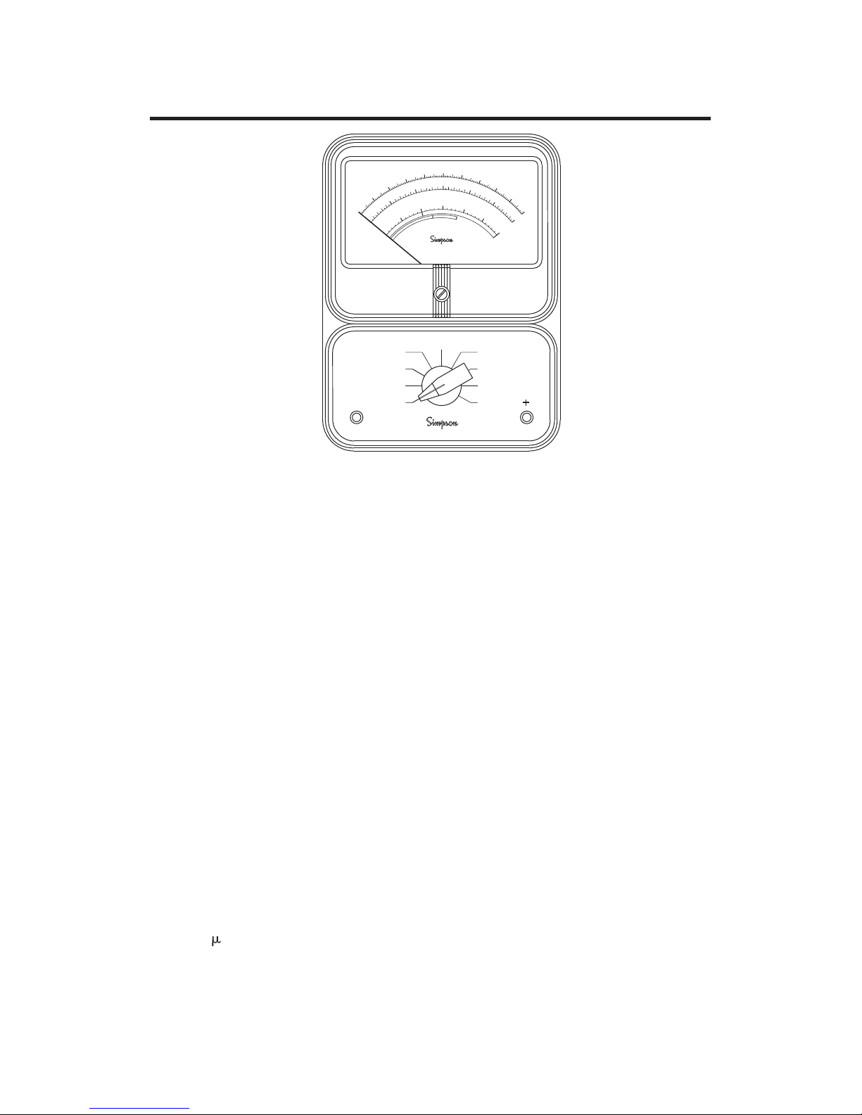
1. Turn the function selector switch to the BATT. TEST position. The pointer
will deflect to the right-hand side of the dial if the battery is OK, as indicated on the lower most arc.
2. With the appropriate voltage range of the Instrument, test for proper line
voltage being applied to the device under test.
3. De-energize the equipment to be tested.
4. Turn the function selector switch to the SHORT TEST position.
5. Connect Model 229-2 Leakage Current Tester, as shown in the figure 2.
Disconnect protective grounding
connection (3rd wire)
Power line
X
Polarity of input leads on
model 229-2 is not important
Figure 2. Model 229-2, Leakage Current Testing Diagram
6. Energize the equipment to be tested. If the pointer is deflected to the red
area (or above) on the second arc from the bottom, immediately turn off
power. The leakage current is greater than 10 mA and a “short” in the
device is probable.
Device under
test
!
Earth Ground
(Water pipe or
power line ground)
Connection to accessible part
being tested
Model 229-2
Model 229-2
Current Leakage
Leakage Current
Te st er
Te st er
9
Page 10

The Model 229-2 will withstand 300V AC (50/60 Hz) on short test for approximately 10 seconds.
7. If the pointer is deflected into the green area, the leakage current may be
measured more accurately by turning the selector switch clockwise until
best reading is obtained.
8. Observe the meter reading. If the device under test has an unpolarized
power plug (2 prong), reverse the plug in the socket and again note the
meter reading. The highest reading obtained is the leakage current. Refer
to the appropriate standard for the limitations of leakage current. As of
1976, the limit is 0.5 milliamperes (subject to change).
NOTE: Leakage current alone is not conclusive evidence of a hazard. The
open circuit voltage between the same two points must be less than 30V rms
for a hazardous condition to exist.
3. MAINTENANCE
The Simpson 229-2 is designed and constructed with high quality components. By providing reasonable care and following the instructions in this
manual the user can expect a long, useful service life from this Instrument.
3.1 Warranty
The Simpson Electric Company warranty policy is printed on the inside front
cover of this manual. Read it carefully before requesting a warranty repair.
NOTE: For assistance of any kind, including help with the Instrument under
warranty, contact the nearest Authorized Service Center for instructions. If
necessary, contact the factory directly, give full details of the difficulty, including the Instrument model number, serial number, and date of purchase. Service data or shipping instructions will be mailed promptly. If nonwarranty or
other service work is required, an estimate of the maximum charge will be
quoted. This charge will not be exceeded without prior approval.
3.2 Shipping
Pack the Instrument carefully and insure and ship it prepaid to the destination
indicated.
3.3 Battery Replacement
This Instrument is powered by one 9V alkaline battery (NEDA 1604A).
NOTE: Battery replacement is indicated whenever insufficient meter deflection occurs in the BATT TEST position.
Turn off all power and remove test leads from the Instrument before removing
its case.
10
Page 11

!
When battery replacement is required, the Instrument must be removed from
its case. To remove the case, proceed as follows:
1. Place Instrument face down on a soft padded surface.
2. Unscrew the four recessed screws located in each corner of the case.
3. Lift the case off the Instrument and set it aside.
4. Remove battery with mating connector from the holder.
5. Remove the old battery from the connector and insert the new battery into
the holder
3.4 Calibration
The Simpson 229-2 is a FACTORY SERVICE ONLY Instrument. If it is suspected that the Instrument is not performing within rated accuracy specifications send Instrument to Simpson Electric Co. for service. Contact Simpson
Technical Support if you are uncertain about performance specifications or
operation of this Instrument.
3.5 Care
Daily
1. If something is spilled on the Instrument, immediately shut off the power
from the test setup, disconnect the test leads, and wipe the Instrument
clean and allow to dry. If the spillage is corrosive, use a suitable cleaner
to neutralize the corrosive action, and remove the spillage.
2. When Instrument is not in use, rotate the function/range selector switch to
the OFF position.
3. Whenever possible, avoid prolonged exposure or usage in areas subject to temperature and humidity extremes, vibration or mechanical shock,
dust or corrosive fumes, or strong electrical or electromagnetic interferences.
Quarterly:
1. Verify Instrument accuracy by performing operational checks using known
accurate, stable sources. If the need for recalibration is indicated, contact your nearest Simpson Authorized Service Center.
2. If the Instrument has not been used for 90 days, check the batteries for
chemical leakage and replace if necessary.
Annually:
It is recommended that the Instrument be returned annually to your nearest
Simpson Authorized Service Center for a complete overall check, adjustment
and calibration.
Storage:
When not in use, store Instrument in a location free from temperature extremes, dust, corrosive fumes, and mechanical vibration or shock. If storage
time exceeds 90 days, remove the battery.
11
Page 12

SIMPSON ELECTRIC COMPANY 520 Simpson Avenue
Lac du Flambeau, WI 54538-0099 (715) 588-3311 FAX (715) 588-3326
Printed in U.S.A. Part No. 05-115705 Edition 12 07/17
Visit us on the web at: www.simpsonelectric.com
 Loading...