

Page 1
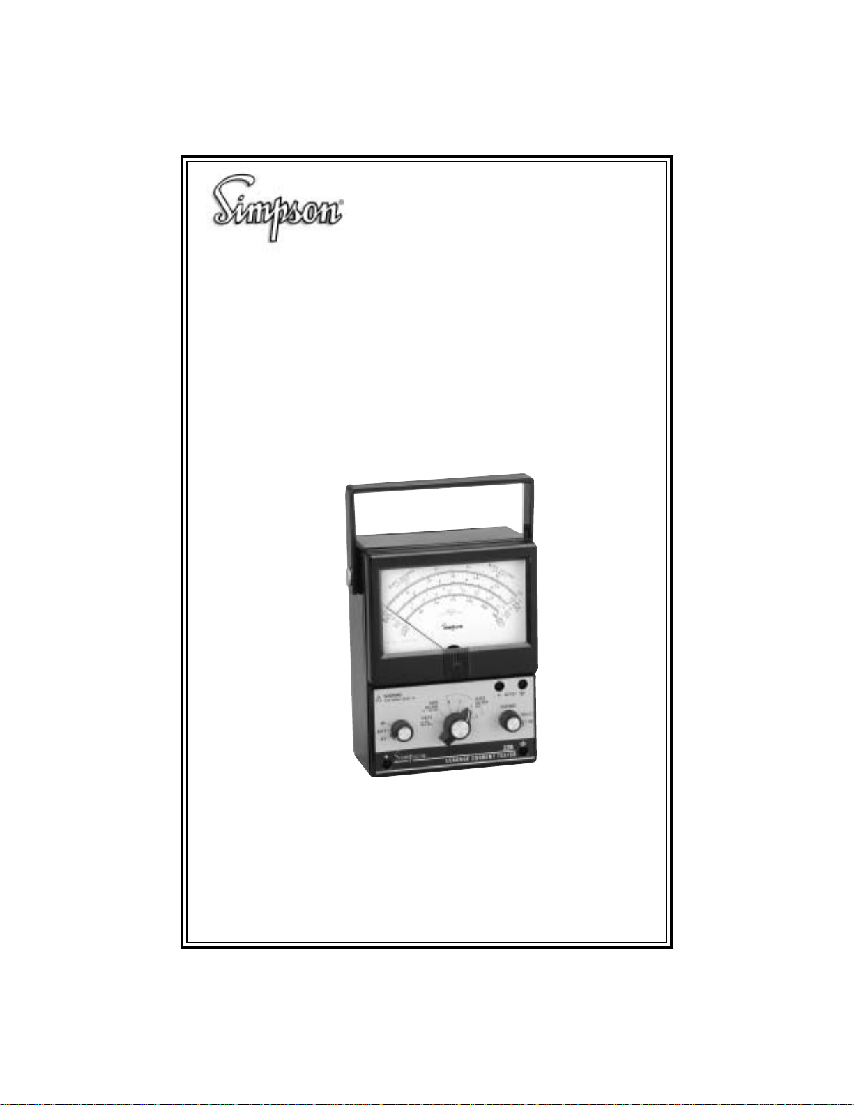
Model 228
Current Leakage Tester
INSTRUCTION MANUAL
1
Page 2
About this Manual
To the best of our knowledge and at the time written, the information contained in
this document is technically correct and the procedures accurate and adequate
to operate this instrument in compliance with its original advertised specifications.
Notes and Safety Information
This Operator’s Manual contains warning headings which alert the user to check
for hazardous conditions. These appear throughout this manual where applicable and are defined below. To ensure the saf ety of operating performance of
this instrument, these instructions must be adhered to.
Warning, refer to accompanying documents.
!
Caution, risk of electric shock.
Technical Assistance
SIMPSON ELECTRIC COMPANY off ers assistance Monday through Friday
7:30 am to 5:00 pm Central Time by contacting Technical Support or
Customer Service at (847) 697-2260.
Internet: http://www.simpsonelectric.com
Warranty and Returns
SIMPSON ELECTRIC COMPANY warrants each instrument and other articles
manufactured by it to be free from defects in material and workmanship under
normal use and service, its obligation under this warranty being limited to making
good at its factory or other article of equipment which shall within one (1) year
after delivery of such instrument or other article of equipment to the original
purchaser be returned intact to it, or to one of its authorized service centers, with
transportation charges prepaid, and which its examination shall disclose to its
satisfaction to have been thus defective; this warranty being expressly in lieu of
all other warranties expressed or implied and of all other obligations or liabilities
on its part, and SIMPSON ELECTRIC COMPANY neither assumes nor authorizes any other persons to assume for it any other liability in connection with the
sales of its products.
This warranty shall not apply to any instrument or other article of equipment
which shall have been repaired or altered outside the SIMPSON ELECTRIC
COMPANY factor y or authorized ser vice centers, nor which has been subject to
misuse, negligence or accident, incorrect wiring by others, or installation or use
not in accord with instructions furnished by the man ufacturer.
This manual represents your meter as manufactured at the time of publication. It
assumes standard software. Special versions of software may be fitted, in which
case you will be provided with additional details.
The apparatus has been designed and tested in accordance with EN 61010-1,
“Safety Requirments for Electrical Equipment for Measurement, Control and Laboratory Use.” This operationg guide contains information and warnings that must
2
Page 3
be followed by the user to ensure safe operation and to maintain the apparatus in
a safe condition.
We reserve the right to make changes and improvements to the product without
obligation to incorporate these changes and improvements into units previously
shipped.
High Voltage Terminal: Use extreme care when making high voltage
measurements; do not touch terminals or probe ends.
Limit voltage, with respect to earth g round, to 600VDC/VAC maximum.
A terminal connected to earth ground.
!
This Instrument is designed to prevent accidental shock to the operator when
properly used. However, no engineer ing design can render safe an instrument
which is used carelessly. Therefore, this manual must be read carefully and com-
pletely before making any measurements. Failure to follow directions can result
in a serious or fatal accident.
SHOCK HAZARD: As defined in IEC-1010-2,
& Electronic Measurement, Control and Laboratory Use,
considered to exist at any part involving a potential in excess of 30 volts RMS
(sine wave) or 42.4 volts DC or peak and where a leakage current from that part
to ground exceeds 0.5 MIU (Measurement Indication Units) when measured
with an appropriate measuring instrument defined in Section 6.3.1.2 annex A of
IEC-1010-1.
NOTE: UL-1244 calls for the same voltage and measurement limits as IEC-10101:1990 but UL-1244 specifies a slightly different test network. Simpson Electric manufactures test equipment to measure shock hazard as set forth by both specifications. The Simpson Model 228 uses the networks specified by IEC-1010-1 and is
suitable for measuring shock hazard as defined in that document. The Simpson
229-2 uses the measurement networks specified in UL-1244 and is suitable for
measuring shock hazard as defined in that document.
Instruments such as the Model 228 are intended for use in relatively low power 120/
240 VAC or dry battery operated circuits. Never use this Instrument for measure-
ments in high-energy or high-power circuitry such as power substations, distribution
centers, RF induction heaters, broadcast transmitters and X-ray equipment. The
Safety Precautions in this manual aler t you to such hazards and the protective
measures necessary to avoid injury or equipment damage. The dangers in high power
circuits are serious. Please observe all safety precautions!
Safety Requirements for Electrical
a shock hazard shall be
3
Page 4

Contents
1. INTRODUCTION ............................................................................... 5
1.1 General Description ...............................................................................5
1.2 What Is Leakage Current? .....................................................................5
1.3 Human Response to Electrical Shock ................................................... 6
1.4 Shock Hazard ......................................................................................... 7
1.5 Burn Hazard ........................................................................................... 7
1.6 Inspection of Instrument .........................................................................7
1.7 Components and Accessories ............................................................... 7
2. SPECIFICATIONS .............................................................................8
3. CONTROLS AND FUNCTIONS .........................................................9
4. INTERPRETING THE METER DIAL SCALES................................. 10
5. READING THE METER DIAL SCALES ........................................... 11
6. SAFETY PRECA UTIONS................................................................ 11
7. MEASUREMENT PROCEDURES...................................................12
7.1 General ................................................................................................12
7.2 Preparation ..........................................................................................13
7.3 Voltage Measurement ..........................................................................13
7.4 Burn Hazard Measurement .................................................................. 1 4
7.5 Shock Hazard Measurement ...............................................................15
7.6 Polar ity Revers al .................................................................................. 1 5
8. MAINTENANCE AND CARE........................................................... 16
8.1 Service .................................................................................................16
8.2 Battery Replacement ...........................................................................16
8.3 Fuse Replacement ...............................................................................1 7
9. CA RE OF INSTRUMENT................................................................. 17
10. RMS VS. PEAK............................................................................... 18
4
Page 5

1. INTRODUCTION
1.1 General Description
The Simpson Model 228 is a special purpose AC/DC milliammeter that measures potentially hazardous leakage current on electrical and electronic equipment. This Instrument meets the guidelines published in IEC 990, “Methods of
Measurement of Touch Current and Protective Conductor Current.” Most standards agencies in the United States — including ANSI, ISA and UL are in the
process of implementing the networks from IEC 990 into their specifications.
NOTE: For specification information call:
ANSI at (212) 642-4900 or
UL in Northbrook, IL at (847) 272-8800.
The Model 228 tests equipment operating at 120-220 volts AC or DC power line
circuits only. Instru ment features include:
• Separate leakage current networks for measuring the following electrical
shock response levels:
Perception/reaction (shock hazard)
Let-go (shock hazard)
Burn hazard
• 0-300 volt scale for measuring open circuit voltage between accessible parts
and ground.
• An RMS reading meter with scales that read shock hazard up to 10 Measurement Indication Units (MIU), burn hazard up to 100 mA and peak indicating
RMS shock hazard. (Refer to Section 7, Measurement Procedures) for more
information.
• Output connections for an external peak reading Instrument (required for
measuring peak readings on non-sinusoidal waveforms).
• Convenient battery test function.
!
The 228 is battery operated. In some applications, the lead attached to the “Ground”
input may not be attached to earth ground. As a result, the output jacks may be
“floating.” To prevent a shock hazard, do not connect any connectors or equipment with accessible conductive surfaces.
1.2 What Is Leakage Current?
“Leakage Current” is a generic term applied to many forms of unwanted currents.
“Leakage Current” (or more accurately, “Touch Current”) as it relates to electrical
shock hazards, is the current that flows to ground through the human body due to
inadequate insulation or improper grounding between internal supplies and accessible conductive parts.
5
Page 6

In properly designed and installed equipment, leakage current can usually be ignored
because it is limited to safe levels. Excessive leakage current can appear in equipment as
a result of:
• A defective component
• Poor equipment design or installation
• A build up of foreign matter
• Old or deteriorated insulation
The presence of leakage current on any accessible conductive part poses a potential shock
hazard to anyone touching that part (see Figure
1). Severe electrical shocks from leakage cur-
rent can cause burns, serious injury and in some
cases, death. Even when leakage currents are
not high enough to directly injure a person, the
current can be high enough to cause a violent
muscle contraction resulting in accident or
injury.
Leakage current measurement ensures the safety of electrical equipment — not
only for the user but for anyone who comes in contact with the equipment. Leakage current measurements should be performed whenever equipment is installed
or repaired.
Electrical shock due to
excess leakage current
(touch current)
Figure 1.
1.3 Human Response to Electrical Shock
The human body’s reaction to electrical shock depends upon the magnitude of
the current involved and many other variables, including sex, weight, age and
point of contact. Reaction to a shock can range from a harmless tingling sensa-
tion to a more serious response such as violent muscle contractions, massive
burns or death due to heart failure.
Although most electrical or electronic equipment is energized by 60Hz (50Hz)
power circuits, some have solid state control circuits or power conversion circuits
which generate higher frequency currents. This high-frequency current may be a
significant part of the total leakage current. The human body becomes less sensitive to leakage current as the frequency is increased. The 228 takes the frequency
of the leakage current into account when making measurements and displays a
reading that correctly reflects the potential hazard from the leakage current. Because of this frequency correction, leakage currents are measured in Measure-
ment Indications Units (MIU).
The IEC and other safety agencies have defined four (two are combined) levels
of human body response to electrical shock:
• Perception/Reaction (tingling sensation and invo luntary muscle contraction)
• Let-go (the loss of the ability to control muscles and release)
• Electric burns
The 228 includes a separate measurement “network” for each of these response
levels.
6
Page 7

!
WARNING: These response networks are for non-medical applications and do
not include patient contact cases. This Instrument is not intended for use in medical applications.
1.4 Shock Hazard
The level at which leakage current will cause a shock varies greatly between
people. As a result the IEC, UL, and other safety agencies set limits where most
people will not feel a shock or will not react to any leakage current present. The
most commonly used leakage current limit is 0.5 MIU RMS (0.7 MIU peak) using
the reaction response network. This level is safe for most conditions and for most
people, but there are cases where 0.5 MIU may pose a hazard. In those cases
tighter limits are required. The safety agencies also acknowledge that some con-
ditions exist where higher currents can be permitted without an increased risk of
injury.
When making routine leakage current measurements as part of equipment maintenance, refer to the equipment manufacturer for the acceptable leakage current
level. When using the 228 for testing safety of new designs, check with the appropriate safety agency for the correct leakage current limits.
1.5 Burn Hazard
Another potential leakage current hazard is electrical burns. Electrical burns can
occur at current frequencies as low as 30KHz or lower. The potential of electrical
burns is constant regardless of frequency and is measured in mA RMS. A limit of
70 mA is almost universally accepted as being a safe limit to prevent leakage
current-related electrical burns.
1.6 Inspection of Instrument
Immediately upon receipt, inspect the Instrument for damage. Verify that your
Instrument includes all of its components and accessories. If you find the unit to
be damaged, notify the carrier and supplier immediately. Do not use a damaged
Instrument.
1.7 Components and Accessories
• Operator’s Manual
• Test Lead Set: Red and black insulated test probe set. Simpson Part Number
00125.
• Tw o (2) 9-volt, NEDA type 1604A alkaline batterie s.
7
Page 8

2. SPECIFICATIONS
noitacificepS
daoLmetsySgnirusaeMtnelaviuqEM1 ⍀ Fp01,M1 ⍀ Fp26,M1 ⍀ Fp1,
segnaRUIM01,3,1,3.0SMRAm001-0
ycaruccAtnerruC
dohteMtnemerusaeMreteM SMReurT
*esnopseRycneuqerFreteM
zH1otCD kaepfo%5nihtiwskcartretnioP
zH91otzH2 detroppustonycaruccA
zHK002otzH02
zHM1otzHK002
ycaruccAtuptuO ⫾ zH06@gnidaeRfo%2
*esnopseRycneuqerFtuptuO
zH05otCD
zHK001otzH05
zHM1otzHK001
*Relative to ANSI C101-1992 or UL-1459 2nd edition
⫾ gnidaeRfo%5.2 ⫹ gnidaeRfo%3-/%2
noitcaeRoG-teLdrazaHnruB
⫾ zH06@SF%2
⫾ SF%2 ⫾ SF%5.2 ⫾ SF%2
⫾ SF%2 ⫾ SF%5.2 ⫾ SF%5
⫾ gnidaeRfo%2
⫾ gnidaeRfo%5
Table 1.
leveLesnopseR
Specifications
Output Sensitivity: Full scale meter deflection equals 1 volt
RMS (measured with a 1M⍀, 12 pF load)
Voltmeter Range: 0-300 volts (AC or DC)
Voltmeter Accuracy:
DC to1 Hz: Pointer tracks within 5% of peak
2Hz to 19Hz
(Accuracy not supported)
20 Hz to 1 KHz: ⫾3% FS @ 60Hz (Add ⫾ 1% for every
additional 100Hz)
Voltmeter Frequency Response: DC to 1KHz
⫾ fo%2
gnidaeR
Power Source Requirements: Two (2) 9 volt, NEDA type 1604A alka
line batteries
NOTE: Alkaline batteries have a VDC continuous use rated life of 400 hours
or longer.
Temperature Range:
Operating: 0° to 40°C
Storage: -10° to 55°C
Humidity Range:
Operating: 70% RH, non-condensing
Dimensions: 7" x 5¼” x 3-1/8" (18 cm x 13.6 cm x
8.2cm)
8
Page 9

Weight: 2½ lbs. (1,134 g)
Low-Battery Indication: Instrument provides a battery test selection on
power switch and corresponding scale on
meter dial.
3. CONTROLS AND FUNCTIONS
.
8
2
6
.
6
.
5
2
0
1
0
2
1
3
0
SHOCK
HAZARD
(MIU)
.3
.
0
.
0
.
0
2
B
U
R
N
H
m
A
A
Z
R
A
.
M
.
8
S
0
.
2
.
5
.
8
1
.
3
2
.
5
4
1
5
.
.
0
0
4
M
P
3
IU
0
E
0
V
A
O
K
R
L
.M
T
S
.S
OUTPUT
+
RESPONSE
228
Response Network
Select Switch
R
D
1
0
0
3
.
0
1
.
0
M
R
I
U
.
M
.
S
Mechanical Zero
Adjustment Screw
REACT.
LET GO
Meter Dial
A
Z
A
H
N
M
.
R
R
U
A
B
m
0
0
0
.S
IU
M
0
.M
0
R
K
IU
A
S
M
E
T
P
L
O
M
V
.
R
!
WARNING
READ MANUAL BEFORE USE
ON
BATT.
OFF
+
Power
Control Switch
0
4
D
R
.
S
.
0
2
5
.
2
.
2
.
5
.
0
S
.
VOLTS
300 Volts max
0
.
1
0
5
HAZARD
DC-1KHz
.
BURN
4
0
.
1
4
.
6
.
5
.
1
0
0
1
10
(0-100mA)
Function
Select Switch
5
.
1
2.0
150
BATT.
OK
3
LEAKAGE CURRENT TESTER
Figure 2. Controls and Functions
Mechanical Zero Adjustment Screw
Adjusts the meter pointer to zero when the instrument is turned OFF.
Power Control Switch
Turns the Instrument ON and OFF. Select the BATT setting before each use to
determine battery condition. A weak battery may cause inaccurate readings.
Function Select Switch
Selects one of three operating modes: VOLTS, BURN HAZARD and SHOCK HAZ-
ARD.
Response Network Select Switch
Selects one of two shock hazard response networks: REACT and LET GO. This
switch is used in conjunction with the SHOCK HAZARD setting on the Function
Select Switch.
Meter Dial
Displays Instrument measurements. The meter dial has four measurement scales
and a battery test scale.
9
Page 10

Burn Hazard Scale (measured in mA RMS)
Used when selecting the BURN HAZARD function in order to read potential burn
hazard leakage current.
Shock Hazard Scales (measured in MIU RMS and MIU Peak)
Used when selecting the SHOCK HAZARD function in order to measure shock
hazard leakage current. The MIU Peak scale reads 1.4 times the RMS value and
assumes a sinusoidal waveform.
Important: Read the MIU Peak scale only if the equipment specification calls for
a peak reading and when certain that the leakage current is sinusoidal. See
Section 10, RMS VS. PEAK, for more infor mation on RMS and Peak measurement limits.
Volts Scale (0-300 volts)
Used when selecting the VOLT S function.
Battery Scale
Indicates battery condition when selecting the BATT function.
4. INTERPRETING THE METER DIAL SCALES
Use the correct multiplier when reading Instrument measurements. R efer to T a ble 2 below.
Table 2
detceleSegnaRelacSreilpitluMegnaR
TTABKOYRETTABenoN
STLOVV003-01
DRAZAHNRUBSMRAm001-01
SMRUIM1-001
UIM01
UIM3
UIM1
UIM3.0
kaePUIM4.1-001
SMRUIM3-01
kaePUIM2.4-01
SMRUIM1-01
kaePUIM4.1-01
SMRUIM3-01.0
kaePUIM2.4-01.0
10
Page 11

5. READING THE METER DIAL SCALES
The analog meter scales require interpolation to obtain readings that fall in between the major scale markings. See Figure 3 below, as example.
Example: Burn hazard reading is 50mA RMS or
MIU (bottom) reading is 1.5 MIU for the 3 MIU range
40
0
.
1
5
.
1
Figure 3
60
2
.
0
1
0
0
“+” and “ W” Input Jacks
Connect the red (positive) test lead to the “+” jack and the black (ground) test lead
to the “W” jack.
“+” and “ W” Output Jacks
Connect the positive and ground leads from a peak reading device to these jacks.
The Instrument output produces a scaled and buffered output voltage which
matches the waveform of the leakage current. At full scale meter deflection, the
output produces 1 volt RMS.
The output jack ground is tied to input jack ground. To avoid a “ground loop”
condition, which can cause false readings or Instrument damage, do not tie the
Instrument’s
output
ground jack to another ground.
Battery Compartment
Compartment houses the two (2) 9 volt NEDA type 1604A alkaline batteries and
input protection fuse. These are the only user serviceable parts in the Instrument.
!
Before opening the Instrument battery compartment, disconnect all test leads
and turn the power switch OFF.
6. SAFETY PRECAUTIONS
!
Although designed to ensure operator safety, this instrument measures potentially fatal current and voltage level s. To guarantee safe operation, observe all
warnings and cautions contained in this manual and in the technical manuals of
the equipment under test.
11
Page 12

Do not use this Instrument unless qualified to recognize shock hazards and
trained in the safety precautions required to avoid injury. Become familiar with the
Definition of Shock Hazard explained on Page 3 of this manual.
1. Do not work alone when measuring where a shock hazard may exist. Make
certain that someone capable of giving aid is close by and is alert to potential
problems.
2. Turn OFF the power to the equipment under test. Discharge any capacitors in
the circuit before connecting or disconnecting the Instrument.
3. Be aware that voltages can appear unexpectedly in defective equipment.
For example, an open bleeder resistor can allow a capacitor to retain a dangerous charge.
4. Locate all voltage sources and accessibility paths before making any connections or measurements.
5. Before using the Instrument, inspect the test leads and connectors for damage.
Do not use, or permit the use of, damaged equipment.
6. Make sure hands and shoes, as well as floor and workbench, are dry.
Avoid making measurements under damp and humid conditions.
7. Never touch the test leads, circuit or Instrument while power is applied to the
circuit being measured.
8. Do not use test leads different from those originally furnished with the Instrument.
7. MEASUREMENT PROCEDURES
7.1 General
Measurement of current leakage involves a series of procedures:
1. Preparation
2. Voltage Measurement
3. Burn Hazard Network Measurement
4. Shock Hazard Network Measurement
5. Polarity Reversal Measurements
For a typical single unit test, all procedures are performed in sequence and the
instructions that follow cover the complete series. However, for testing of a group
of products or for special purpose applications, qualified users might only need to
use a selected part of the full procedure.
!
Do not touch the equipment under test with power applied until voltage and
current leakage measurements are within accepted limits.
NOTE: Th e following is based on set-up and test procedures from the applicable
standards document (or from the equipment manufacturer) for correct main connection, detailed test procedures and leakage current limits.
Figure 4, Page 13, shows a typical test setup. All items other than the 228 and its
accessories m ust be pr ovided by the user.
12
Page 13

SW 2
B
0
4
D
R
A
Z
A
.
H
S
.
N
M
.
R
R
U
A
0
B
0
.
1
2
m
5
.
2
.
5
.
4
1
.
0
.
1
0
.2
0
1
0
5
.
0
0
5
.S
MIU
0
0
R.M
K
U
I
A
0
S
M
E
T
P
L
S
.
O
M
V
.
R
U
6
0
R
N
H
m
A
A
Z
R
A
5
.
1
.
R
M
D
.
8
S
2
0
.
.
0
.
6
4
.
2
.
8
.6
.
5
.
8
2.0
2
.
1
5
.
0
3.0
1
0
0
1
150
.
3
2
2
.
0
BATT.
OK
3
5
0
0
.
0
1
.
0
M
R
I
2
4
U
1
5
.
.
.
0
0
M
4
.
S
MIU
PEAK
3
0
0
V
O
R
L
.
M
T
S
.
S
120V
+
_
Open
SW1
Ground
Grounded
Supply
Connector
Appliance
Under T est
!
WARNING
READ MANUAL BEFORE USE
ON
BATT.
OFF
+
SHOCK
3
10
HAZARD
BURN
(MIU)
1
HAZARD
(0-100µA)
VOLTS
3
DC-1KHz
300 Volts max
LEAKAGE CURRENT TESTER
Figure 4. Typical Test Setup
7.2 Preparation
1. Turn p ower OFF to equipment under test.
2. If the meter pointer does not align with zero when Instrument power is OFF,
rotate the mechanical zero adjustment screw as necessary.
3. Connect the Instrument and equipment under test. Figure 4, above, shows a
typical test setup. Do not apply power.
4. Verify that proper line voltage is available for the equipment under test.
5. Turn the Instr ument Power Switch to BATT. If pointer indicates satisfactor y
battery condition, proceed with testing. If not, turn Instr ument Power Switch to
OFF and replace the batteries before proceeding.
+
RESPONSE
228
OUTPUT
REACT.
LET GO
7.3 Voltage Measurement
1. Turn the Instrument Power Switch to ON (see figure 5 below)
!
WARNING
READ MANUAL BEFORE USE
ON
BATT.
VOLTS
DC-1KHz
300 Volts max
OFF
+
LEAKAGE CURRENT TESTER
Figure 5
2. Connect Instrument T est Leads to the input jacks — red lead to “+” and
black lead to “W”.
13
OUTPUT
+
RESPONSE
228
REACT.
LET GO
Page 14

3. Turn Function Select switch to VO LTS.
4. Connect Instrument Ground Test Lead to known good ground (such as a water
pipe or power line ground).
5. With SW1 open, turn ON equipment under test.
6. Use Positive Test Lead to probe all accessible conductive surfaces to determine
if excessive voltage is present. Read the 0-300 volts (bottom) scale.
a. If the voltage measurements appear normal, proceed to Burn Hazard test
which follows.
b. If measured voltage is above expected value, check equipment for short cir-
cuits and make any necessary repairs before continuing. Abnormally high
voltages that persist without corresponding short circuits indicate current
leakage.
7.4 Burn Hazard Measurement
1. Turn Function Select switch to BURN HAZARD (see Figure 6 below).
!
WARNING
READ MANUAL BEFORE USE
HAZARD
ON
BATT.
OFF
(0-100mA)
BURN
10
HAZARD
(MIU)
1
.3
SHOCK
3
OUTPUT
+
RESPONSE
REACT.
LET GO
+
228
LEAKAGE CURRENT TESTER
Figure 6
2. Use Positive Test Lead to probe all accessible conductive surfaces and check
for excessive current leakage. Read the 0-100mA RMS scale.
NOTE: Most safety specifications set a limit of 70mA for this measurement. Refer to
the appropriate specification (or equipment manufacturer) for the correct limit. Proceed only when burn hazard measurements are within acceptable limits.
14
Page 15

7.5 Shock Hazard Measurement
1. Turn Function Select Switch to 10MIU SHOCK HAZARD (see Figure 7 below).
!
WARNING
READ MANUAL BEFORE USE
ON
BATT.
OFF
BURN
HAZARD
(0-100mA)
10
HAZARD
(MIU)
1
.3
SHOCK
3
OUTPUT
+
RESPONSE
REACT.
LET GO
+
LEAKAGE CURRENT TESTER
228
Figure 7
2. Use Positive Test Lead to probe all accessible conductive surfaces and check
for excessive current leakage. Read the 0-10 MIU scale. If measured current is
less than 1/3 of full scale, increase meter sensitivity by turning the Function
Select switch clockwise until pointer is in upper 2/3 of the dial.
Note: ANSI C101.1 limits current leakage to 0.5 MIU RMS for most appliances, but
exceptions are allowed for unique situations. Refer to the equipment manufacturer or
applicable safety standard for more details. Proceed only when shock hazard measurements are within acceptable limits.
7.6 Polarity Reversal
1. Use SW2 switch (see figure 4, page 13) to reverse the hot and neutral. Do not
close SW1 to activate the unit under test. Repeat Voltage, Bur n Hazard, and
Shock Hazard tests. After completing tests, return SW2 to original position.
2. Close SW1 and turn equipment on.
3. Use Po sitive Test Lead to probe all accessible conductive surfaces in order to
determine if excessive voltage is present. Read the 0-300 volts (bottom) scale.
a. If the voltage measurements appear normal, proceed to step 4.
b. If measured voltage is above expected value, check equipment for short cir-
cuits and make any necessary repairs before continuing. Abnormally high voltages that persist without corresponding short circuits indicate current leakage.
4. Turn Function Select switch to BURN HAZARD (see Figure 6, page 14).
5. Use Positive Test Lead to probe all accessible conductive surfaces and check
for excessive current leakage. Read the 0-100mA RMS scale.
NOTE: Most safety specifications set a limit of 70mA for this measurement. Refer to
the appropriate specification (or equipment manufacturer) for the correct limit. Pro-
ceed only when burn hazard measurements are within acceptable limits.
15
Page 16

6. Tu rn Function Select Switch to 10 MIU, SHOCK HAZARD.
7. Use Positive Test Lead to probe all accessible conductive surfaces and check
for excessive current leakage. Read the 0-10 MIU scale. If measured current is
less than 1/3 of full scale, increase meter sensitivity by turning the Function
Select switch clockwise until pointer is in upper 2/3 of the dial.
NOTE: ANSI C101.1 limits current leakage to 0.5 MIU RMS for most appliances, but
exceptions are allowed for unique situations. Refer to the equipment manufacturer’s
applicable safety standard for more details.
8. Repeat steps 3 throught 7 for both positions of SW2 within 5 seconds of closing
SW1. If the equipment has multiple separate conductive surfaces, repeat steps
3-8 as quickly as possible for each surface.
9. Continue monitoring leakage current, using the procedure outlined in steps 3-8
above, while equipment warms up and operates nor mally.
10. Open SW1 and monitor leakage current (using the procedure outlined in steps
3-8 above) until equipment cools or until leakage current stabilizes.
NOTE: If at any time during the test, the equipment under test exceeds the limits
specified by the appropriate safety standard (or by the manufacturer), replace the
equipment or remove it from service until the necessary repairs are complete.
8. MAINTENANCE AND CARE
!
This Instrument is constructed with high-quality components. Providing reasonable
care and routine maintenance will ensure a long service life of trouble-free operation.
8.1 Service
The Model 228 Current Leakage Tester contains no operator-serviceable parts, except for the batteries and the fuse. Refer all service requests to an authorized service
dealer or to the factory.
8.2 Battery Replacement
To install 9 volt NEDA type 1604A alkaline batteries:
1. T urn OFF the Instrument and disconnect the Instrument test leads before opening
the battery compartment.
2. Place the Instrument face-down on a soft, padded surface.
3. Using a flat-blade screwdr iver, loosen the large captive screw holding the
battery compartment cover and remove cover.
4. Replace both batteries.
16
Page 17

Whenever the Battery Check indicates low battery power, always replace both batteries.
5. Replace battery com partment cover.
8.3 Fuse Replacement
To replace a blown fuse:
1. T urn OFF the Instrument and disconnect the Instrument test leads before opening
the battery compartment.
2. Place the Instrument face-down on a soft, padded surface.
3. Using a flat-blade screwdr iver, loosen the large captive screw holding the
battery compartment cover. Remove cover.
4. Carefully remove the blown fuse and replace with fresh fuse.
Use a fuse of specified size and rating:
Size: 1/4" x 1-1/4"
Rating: 0.1A, 250V
Fuse is Littlefuse model 312.1 or equivalent and is available through
electric supply sources.
5. Replace the battery compartment cover.
9. CARE OF INSTRUMENT
Do not attempt to clean this Instrument with the test leads connected to a power
source or when it is connected to the AC power line.
1. Immediately clean spilled materials from the Instrument and wipe dry. If necessary, moisten a cloth with soap and water to clean plastic surfaces.
2. Avoid exposing Instrument to temperature and humidity extremes, vibration,
mechanical shock, dust, corrosive fumes, or strong electrical or electromagnetic
interferences.
3. V erify I nstrument calibrat ion by performing operational checks using known v alue
sources. For information on Instrument calibration, call Simpson Customer Service.
4. It is recommended that the Instrument be returned annually to the factory for
inspection and calibration. Call Simpson Customer Service for instructions.
5. When not in use, store Instrument in a location free from temperature extremes,
dust and corrosive fumes, mechanical vibration and shock.
17
Page 18

10 . RMS VS. PEA K
Throughout this manual there have been frequent notices about using the meter
to measure sinusoidal currents only. These warnings are necessary because of
the nature of leakage current and its effect on the body.
Almost all studies investigating electrical shock hazard have shown that the se-
verity of an electric shock is more closely related to peak current than the average
value or RMS value. As a result, the authors of IEC 990 decided that a peak
reading Instrument was the best Instrument for measuring shock hazard. Measuring peak current can be a difficult task in a noisy environment or when the unit
under test is producing high frequency signals. The ANSI C101.1 committee felt
that this difficulty was a significant problem and specified an RMS reading Instrument for measuring leakage current.
The Model 228 attempts to resolve the differences in specifications by providing
a direct reading RMS meter and by providing a buffered output for measuring
peak current. The Instrument provides a peak reading scale on the dial as a
convenience for users who have verified that a sinusoidal current is present.
The output on the Model 228 provides the user with the ability to measure the
waveform that comes out of the measurement network.
When measuring non-sinusoidal currents, take precautions to insure that the
peak levels of current do not overload the inter nal amplifiers in the meter. The
simplest method of doing this is to connect a peak reading instrument to the
Model 228 ouput. After identifying the appropriate range, select the next highest
range and compare the reading. If the readings match (after adjusting for attenuator scale factor), then the amplifiers are not in overload, and the more sensitive
range may be used. If the readings do not match, the Model 228 is overloaded,
and a higher range must be used.
When high crest factors are present, the difference between the RMS and the
peak readings may be substantial. In those cases, it may be advisable to base
safety on the peak reading even though ANSI C101.1 calls for RMS.
When using the Model 228, it is important to use the correct measurement limits.
Contact the appropriate safety agency or the equipment manufacturer to determine whether RMS or peak measurements are required.
18
Page 19

NOTES
19
Page 20

SIMPSON ELECTRIC COMPANY 853 Dundee Avenue
520 Simpson Avenue, Lac Du Flambeau, WI 54538-0099
Elgin, IL 60120-3090 (847) 697-2260 FAX (847) 697-2272
Printed in U.S.A. Part No. 06-115537 Edition 4, 7/04
Visit us on the web at: www.simpsonelectric.com
20
 Loading...