

Page 1

How to use this file...(Parts Manuals)
————————————————————————————————————————————–––
Instructions for
Print Vendors (Paper Manuals)
Paper Size: * 11 x 17
* Body—50 lbs brilliant white offset or equivalent.
* Cover—on pre-printed grid stock whenever available.
Press: * Body—1-color, 2-sided
* Cover—1-color, 1-sided
Bindery: * If LESS than 30 sheets—Saddle Stitch, Face Trim, 3-Hole Drill
* If MORE than 30 sheets—Perfect bind with black tape
* Face Trim
* 3-Hole Drill
General: * This instruction page is NOT part of the manual and must NOT be printed.
* Front cover is page 2 of this file.
* Back cover is the LAST page of this file.
* Odd number pages of body (text part listings) are ALWAYS right hand pages.
* EVEN number pages of body (exploded views) are ALWAYS left hand pages.
• Pages labeled with the text “THIS PAGE INTENTIONALLY BLANK” are placement pages for
microfiche vendors, and should NOT be printed unless necessary to fill up an appropriate
signature.
————————————————————————————————————————————–––
Instructions for
Microfiche Vendor
Cover Pages: * Cover (page 2 in this file) is equivalent to page ZERO (0) and should be combined with the next
page {either the Table of Contents page (numbered as “1” on the bottom of the IMAGE)—or the
page with the text “THIS PAGE INTENTIONALLY BLANK” } to form the first LH-RH page group on
the microfiche row.
* Back Cover is the LAST page of this file, and should NOT be imaged onto fiche.
Body Pages: * Odd number pages of body (text part listings) are ALWAYS right hand pages.
* EVEN number pages of body (exploded views) are ALWAYS left hand pages.
Row/Grid: * Consult the jobs notes for the individual fiche card for the placement of images onto the grid.
General: * This instruction page is NOT part of the manual and must NOT be imaged.
————————————————————————————————————————————–––
Instructions for
EPC Conversion Vendors
General: * This instruction page is NOT part of the manual and must NOT be converted.
• See the job notes for further instructions on conversion of files.
————————————————————————————————————————————–––
Page 2

Page 3
Parts Manual
Rev. 09/2002
TP 400-2307-03-LW-S
LARGE FRAME
S
NOWTHROWERS
(M
ODELS 860, 970 & 1180)
M
ODEL 860 SNOWTHROWERS
Mfg. No. Description
1693650 860M, 8HP Snowthrower
1693651 860M, 8HP Snowthrower (Export)
1693763 860M, 8HP Snowthrower
1693775 860M, 8HP Snowthrower (Export)
1693984 860M, 8HP Snowthrower
1693985 860M, 8HP Snowthrower (Export)
1694242 860E, 8HP Snowthrower
MODEL 860DLX SNOWTHROWERS
Mfg. No. Description
1693652 860DLX, 8HP Snowthrower
1693653 860DLX, 8HP Snowthrower (Export)
1694241 860DLXE, 8HP Snowthrower
M
ODEL 970 SNOWTHROWERS
Mfg. No. Description
1693654 970M, 9HP Snowthrower
1693655 970M, 9HP Snowthrower (Export)
1694243 970E, 9HP Snowthrower
MODEL 1180 SNOWTHROWERS
Mfg. No. Description
1693656 1180M, 11HP Snowthrower
1693657 1180M, 11HP Snowthrower (Export)
1694244 1180E, 11HP Snowthrower
Page 4

Page 5

1
TP 400-2307-03-LW-S
Table of Contents
SNOWTHROWER COMPONENTS PAGES
Handles and Controls Group ....................................2
Engine & Frame Group - 8HP, Manual Start .........14
Engine & Frame Group - 8HP, Manual Start .........16
Engine & Frame Group - 8HP, Manual Start .........20
Engine & Frame Group - 8HP, Electric Start .........22
Engine & Frame Group - 8HP, Electric Start .........24
Engine & Frame Group - 9HP, Manual Start .........28
Engine & Frame Group - 9HP, Electric Start .........32
Engine & Frame Group - 11HP, Manual Start .......36
Engine & Frame Group - 11HP, Electric Start .......40
Auger and Impeller Group - 24”..............................44
Auger and Impeller Group - 28”..............................46
Auger and Impeller Group - 32”..............................48
Auger Housing and Chute Group - 24”....................50
Auger Housing and Chute Group - 28”....................52
Auger Housing and Chute Group - 32”....................54
Traction Drive Group...............................................56
Decals Group - 860.................................................68
Decals Group - 860DLX, 970 & 1180 ........................70
Wheels and Tires Group - 860 ................................72
Wheels and Tires Group - 860DLX & 970..................74
Wheels and Tires Group - 1180 & 1390 ..............................76
Headlight Group......................................................78
REFERENCE INFORMATION
Torque Specification Chart..............Inside Back Cover
© Copyright 2002 Simplicity Manufacturing, Inc. All Rights Reserved.
Page 6
2
TP 400-2307-03-LW-S
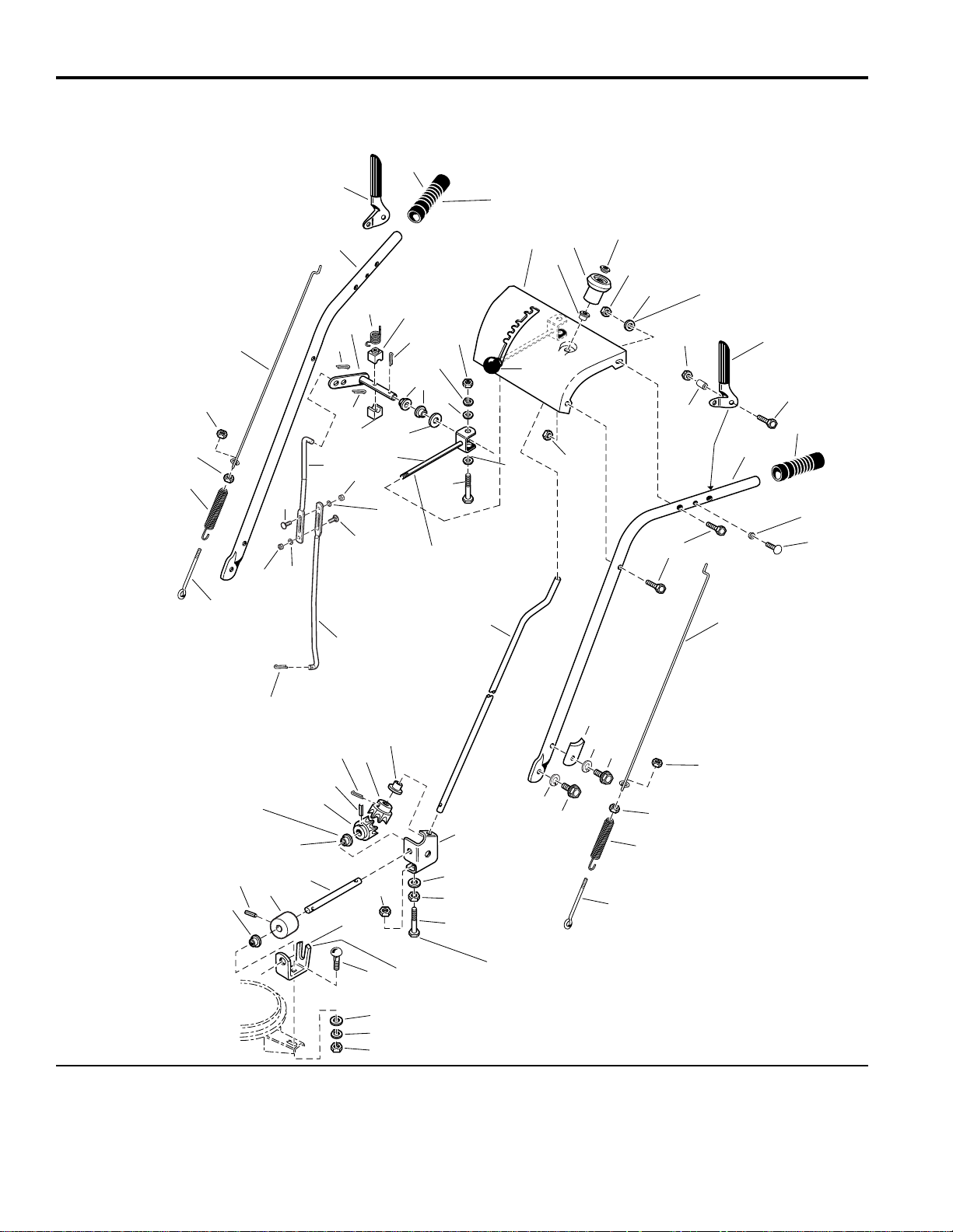
Handles and Controls Group
NOTE: Unless noted otherwise,
use the standard hardware torque
specification chart.
985771
The holes in the frame for Ref. 27 are
slotted so the gear support (Ref. 42) can
be positioned to ensure the inside surface
of the gear support is tight against the
hub of the front gear (Ref. 44).
Mount bushings (Ref. 43)
with flange on inside of
brackets, 3 places.
Ref. 12 required on
slotted holes only.
Slot towards
rear of unit.
Shift rod assembly (Ref. 38)
must pivot freely on
pivot blocks, (Ref. 33).
Apply adheasive to
secure grips.
1
2
3
3
4
5
6
7
8
9
10
11
12
13
14
16
18
7
4
2020
21
22
23
24
3
3
53
54
25
26
27
28
29
28
29
30
31
32
33
34
36
37
35
25
25
33
28
29
11
38
39
40
37
41
42
43
44
47
48
49
50
52
22
51
44
37
27
34
43
43
15
19
55
46
45
17
27
22
35
50
43
The above parts group applies to the following Mfg. Nos.:
1693650 860M, 8HP Manual Start
1693651 860M, 8HP Manual Start (Export)
1693763 860M, 8HP Manual Start
1693775 860M, 8HP Manual Start (Export)
© Copyright 2002 Simplicity Manufacturing, Inc. All Rights Reserved.
Page 7

3
TP 400-2307-03-LW-S
Handles and Controls Group
1 1668525 1 CLUTCH ROD, Lower, RH
2 1669323 1 SPRING, Extension
3 1916621 4 NUT, Hex, #10-24 RH
4 1715659 2 CLUTCH ROD, Traction & Auger Drive
5 1721564 1 HANDLE, RH
6 1715103 1 LEVER, Auger Clutch, RH
7 1676954 2 GRIP, Black Vinyl, for 1" Tube
8 1722627 1 DASHBOARD & SUPPORT ASSEMBLY
9 1714084 1 KNOB, Chute Control Spinner
10 1960093 1 PUSH NUT, 3/8
11 1919438 4 NUT, Hex Lock, 5/16-18
12 1919326 1 WASHER, Flat 5/16
13 1715104 1 LEVER, Traction Drive Clutch, LH
14 1923358 2 NUT, Hex, Centerlock, 1/4-20
15 1715655 2 SPACER, Large
16 1721563 1 HANDLE, LH
17 1922837 2 CAPSCREW, Hex Head, 1/4-20 x 1-1/2
18 1715654 2 SPACER, Small
19 1960556 2 SCREW, Taptite, Pan Head, Torx, 1/4-20 x 3/4
20 1921221 4 CAPSCREW, Hex Head, 5/16-18 x 1-1/2
21 1720452 2 CLAMP, Tube, Saddle
22 1917356 5 LOCKWASHER
23 1922127 2 CAPSCREW, Hex Head, 5/16-18 x 1 3/4
24 1921332 2 CAPSCREW, Hex Head, 5/16-18 x 3/4
25 1918447 3 PIN, Cotter
26 1666255 1 ROD, Shift-Lower
27 1960252 3 CARRIAGE BOLT, 1/4-20 X 5/8
28 1916964 3 LOCKWASHER, 1/4
29 1916622 3 NUT, Hex Head, 1/4-20
30 1720238 1 ROD, Shift-Upper
31 1720240 1 ROD & ARM ASSEMBLY, Pivot
32 1715123 1 SPRING, Torsion
33 1668524 2 BLOCK, Pivot
34 1918452 2 PIN, Cotter
35 1668185 2 BUSHING
36 1924361 1 WASHER
37 1921319 2 WASHER, Flat 1/4
38 1668523 1 ROD & CLEVIS ASSEMBLY
39 1921159 1 CAPSCREW, Hex Head, 1/4-20 x 2-1/4
40 8021050 1 KNOB, Internal Thread, 3/8-16
41 1715658 1 ROD, Chute Control
42 1718793 1 SUPPORT, Gear
43 1667588 4 BUSHING, Nylon
44 1718593 2 GEAR, Steel, Universal
45 1931333 1 CARRIAGE BOLT, 5/16-18 x 3/4
46 1919326 1 WASHER, Flat 5/16
47 1611911 1 BRACKET, Worm Support
48 1668186 1 WORM, Chute
49 1668187 1 ROD, Chute, Worm
REF NO. PART NO. QTY. DESCRIPTION
Footnotes:
The above parts group applies to the following Mfg. Nos.:
1693650 860M, 8HP Manual Start
1693651 860M, 8HP Manual Start (Export)
1693763 860M, 8HP Manual Start
1693775 860M, 8HP Manual Start (Export)
Page 8

4
TP 400-2307-03-LW-S
Handles and Controls Group
NOTE: Unless noted otherwise,
use the standard hardware torque
specification chart.
985771
The above parts group applies to the following Mfg. Nos.:
1693650 860M, 8HP Manual Start
1693651 860M, 8HP Manual Start (Export)
1693763 860M, 8HP Manual Start
1693775 860M, 8HP Manual Start (Export)
© Copyright 2002 Simplicity Manufacturing, Inc. All Rights Reserved.
The holes in the frame for Ref. 27 are
slotted so the gear support (Ref. 42) can
be positioned to ensure the inside surface
of the gear support is tight against the
hub of the front gear (Ref. 44).
Mount bushings (Ref. 43)
with flange on inside of
brackets, 3 places.
Ref. 12 required on
slotted holes only.
Slot towards
rear of unit.
Shift rod assembly (Ref. 38)
must pivot freely on
pivot blocks, (Ref. 33).
Apply adheasive to
secure grips.
1
2
3
3
4
5
6
7
8
9
10
11
12
13
14
16
18
7
4
2020
21
22
23
24
3
3
53
54
25
26
27
28
29
28
29
30
31
32
33
34
36
37
35
25
25
33
28
29
11
38
39
40
37
41
42
43
44
47
48
49
50
52
22
51
44
37
27
34
43
43
15
19
55
46
45
17
27
22
35
50
43
Page 9

5
TP 400-2307-03-LW-S
Handles and Controls Group
50 916168 2 PIN, Spring
51 1960294 2 NUT, Hex Flange, 1/4-20
52 1960518 2 PUSH NUT, Bolt Retainer 1/4
53 1668526 1 CLUTCH ROD, Lower, LH
54 1707452 1 SPRING, Clutch Rod
55 1917372 1 NUT, Hex, 5/16-18
REF NO. PART NO. QTY. DESCRIPTION
Footnotes:
The above parts group applies to the following Mfg. Nos.:
1693650 860M, 8HP Manual Start
1693651 860M, 8HP Manual Start (Export)
1693763 860M, 8HP Manual Start
1693775 860M, 8HP Manual Start (Export)
Page 10
6
TP 400-2307-03-LW-S
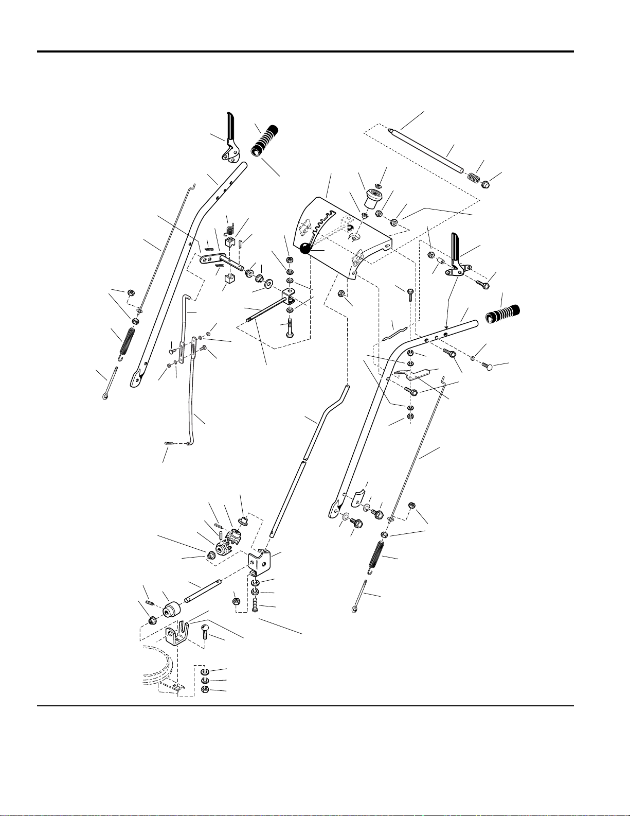
Handles and Controls Group
NOTE: Unless noted otherwise,
use the standard hardware torque
specification chart.
985916
The above parts group applies to the following Mfg. Nos.:
1693984 860M, 8HP Manual Start
1693985 860M, 8HP Manual Start (Export)
1694242 860E, 8HP Electric Start
© Copyright 2002 Simplicity Manufacturing, Inc. All Rights Reserved.
The holes in the frame for Ref. 40 are
slotted so the gear support (Ref. 37) can
be positioned to ensure the inside surface
of the gear support is tight against the
hub of the front gear (Ref. 49).
Mount bushings (Ref. 9)
with flange on inside of
brackets, 3 places.
Ref. 13 required on
slotted holes only.
Slot towards
rear of unit.
Shift rod assembly (Ref. 57)
must pivot freely on
pivot blocks, (Ref. 58).
Apply adhesive to
secure grips.
Insert shift rod (Ref. 55)
into outter hole of Ref. 61.
Must pivot freely
on capscrew (Ref 22).
Apply lubricant as required.
Must slide freely in
dash assembly (Ref 8).
Apply lubricant as required.
1
2
33
4
5
6
7
8
10
11
12
13
17
18
21
26
7
4
2028
30
31
32
33
33
35
34
51
52
40
53
54
53
54
55
61
62
58
50
59
38
35
51
51
58
53
54
12
57
56
63
38
36
37
9
49
42
47
48
46
39
31
41
49
38
40
50
9
9
19
27
45
44
43
20
40
31
60
46
14
15
16
22
23
18
29
1624
25
9
Page 11

7
TP 400-2307-03-LW-S
Handles and Controls Group
1 1668525 1 ROD, Auger, 3 7/16 Long 10-24
2 1669323 1 SPRING, Extension, 3 7/16 Long
3 1916621 1 NUT, Hex Machine Screw, 10-24
4 1715659 2 ROD, Clutch/Traction, 23 1/8 Long
5 1722636 1 HANDLE, RH
6 1722638 1 HANDLE, Clutch, RH
7 1676954 2 GRIP, Black Vinyl
8 1722627 1 DASHBOARD & SUPPORT ASSEMBLY
9 1667588 3 BUSHING, 3/8
10 1714084 1 KNOB, Spinner, 2 1/2 Long
11 1960093 1 PUSH NUT, Pal, 3/8
12 1919438 4 NUT, Hex Lock ESNA Light, 5/16-18
13 1919326 2 WASHER, 5/16
14 1722633 1 ROD & SPRING ASSEMBLY, with Pin
15 1722690 1 SPRING, Compression, 1 7/8 Long
16 1960519 1 PUSH NUT, Stud Cap, 1/2
17 1722667 1 HANDLE, Clutch, LH
18 1923358 2 NUT, Hex Centerlock, 1/4-20
19 1715655 2 SPACER
20 1922837 2 CAPSCREW, Hex Head, 1/4-20 x 1 1/2
21 1722637 1 HANDLE, LH
22 1921962 1 CAPSCREW, Hex Head, 1/4-20 x 1 3/4
23 1722630 1 ROD, 5 3/4 Long
24 1921319 2 WASHER, 1/4
25 1722631 1 LEVER, Pivot
26 1715654 2 SPACER
27 1960556 2 SCREW, Taptite, Pan Head, Torx, 1/4-20 x 3/4
28 1921221 4 CAPSCREW, Hex Head, 5/16 x 1 1/2
29 1920397 2 NUT, Hex Lock ESNA Light, 1/4-20
30 1720452 2 CLAMP, Tube Saddle
31 1917356 3 LOCKWASHER, Spring, 5/16
32 1922127 2 CAPSCREW, Hex Head, 5/16-18 x 1 3/4
33 1921332 2 CAPSCREW, Hex Head, 5/16-18 x 3/4
34 1707452 1 SPRING, Extension, Clutch Rod
35 1668526 1 ROD, Clutch, 6 5/16 Long
36 1715658 1 ROD, Chute Control, 27 Long
37 1718793 1 SUPPORT, Gear
38 1921319 2 WASHER, 1/4
39 1960518 2 PUSH NUT, 1/4
40 1960252 2 CARRIAGE BOLT, 1/4-20 x 5/8
41 1960294 2 NUT, Hex Whiz Lock Flange, Small, 1/4-20
42 1611911 1 SUPPORT, Worm
43 1931333 1 CARRIAGE BOLT, 5/16 x 3/4
44 1919326 1 WASHER, 5/16
45 1917372 1 NUT, Hex, 5/16-18
46 916168 2 PIN, Spring 1/8 x 3/4
47 1668186 1 WORM, Chute, LH
48 1668187 1 ROD, Chute, 17 3/4 Long
49 1718593 2 GEAR, Powder Metal
REF NO. PART NO. QTY. DESCRIPTION
Footnotes:
The above parts group applies to the following Mfg. Nos.:
1693984 860M, 8HP Manual Start
1693985 860M, 8HP Manual Start (Export)
1694242 860E, 8HP Electric Start
Page 12

8
TP 400-2307-03-LW-S
Handles and Controls Group
NOTE: Unless noted otherwise,
use the standard hardware torque
specification chart.
985916
The holes in the frame for Ref. 40 are
slotted so the gear support (Ref. 37) can
be positioned to ensure the inside surface
of the gear support is tight against the
hub of the front gear (Ref. 49).
Mount bushings (Ref. 9)
with flange on inside of
brackets, 3 places.
Ref. 13 required on
slotted holes only.
Slot towards
rear of unit.
Shift rod assembly (Ref. 57)
must pivot freely on
pivot blocks, (Ref. 58).
Apply adhesive to
secure grips.
Insert shift rod (Ref. 55)
into outter hole of Ref. 61.
Must pivot freely
on capscrew (Ref 22).
Apply lubricant as required.
Must slide freely in
dash assembly (Ref 8).
Apply lubricant as required.
1
2
33
4
5
6
7
8
10
11
12
13
17
18
21
26
7
4
2028
30
31
32
33
33
35
34
51
52
40
53
54
53
54
55
61
62
58
50
59
38
35
51
51
58
53
54
12
57
56
63
38
36
37
9
49
42
47
48
46
39
31
41
49
38
40
50
9
9
19
27
45
44
43
20
40
31
60
46
14
15
16
22
23
18
29
1624
25
9
The above parts group applies to the following Mfg. Nos.:
1693984 860M, 8HP Manual Start
1693985 860M, 8HP Manual Start (Export)
1694242 860E, 8HP Electric Start
© Copyright 2002 Simplicity Manufacturing, Inc. All Rights Reserved.
Page 13

9
TP 400-2307-03-LW-S
Handles and Controls Group
50 1918452 2 PIN, Cotter
51 1918447 2 PIN, Cotter
52 1666255 1 ROD, Shift, 3/8 15 5/16
53 1916964 3 LOCKWASHER, Spring, 1/4
54 1916622 3 NUT, Hex, 1/2-20
55 1720238 1 ROD, Upper Shift, 12 1/2 Long
56 1921159 1 CAPSCREW, Hex Head, 1/4-20 x 2 1/4
57 1668523 1 ROD & CLEVIS ASSEMBLY, Shift
58 1668524 2 BLOCK, Pivot, 3/4 x 3/4
59 1924361 1 WASHER, 1/2
60 1668185 2 BUSHING, 1/2
61 1720240 1 ROD & ARM ASSEMBLY, Pivot
62 1715123 1 SPRING, Torsion, 1/2 Long
63 172038 1 KNOB
REF NO. PART NO. QTY. DESCRIPTION
Footnotes:
The above parts group applies to the following Mfg. Nos.:
1693984 860M, 8HP Manual Start
1693985 860M, 8HP Manual Start (Export)
1694242 860E, 8HP Electric Start
Page 14
10
TP 400-2307-03-LW-S
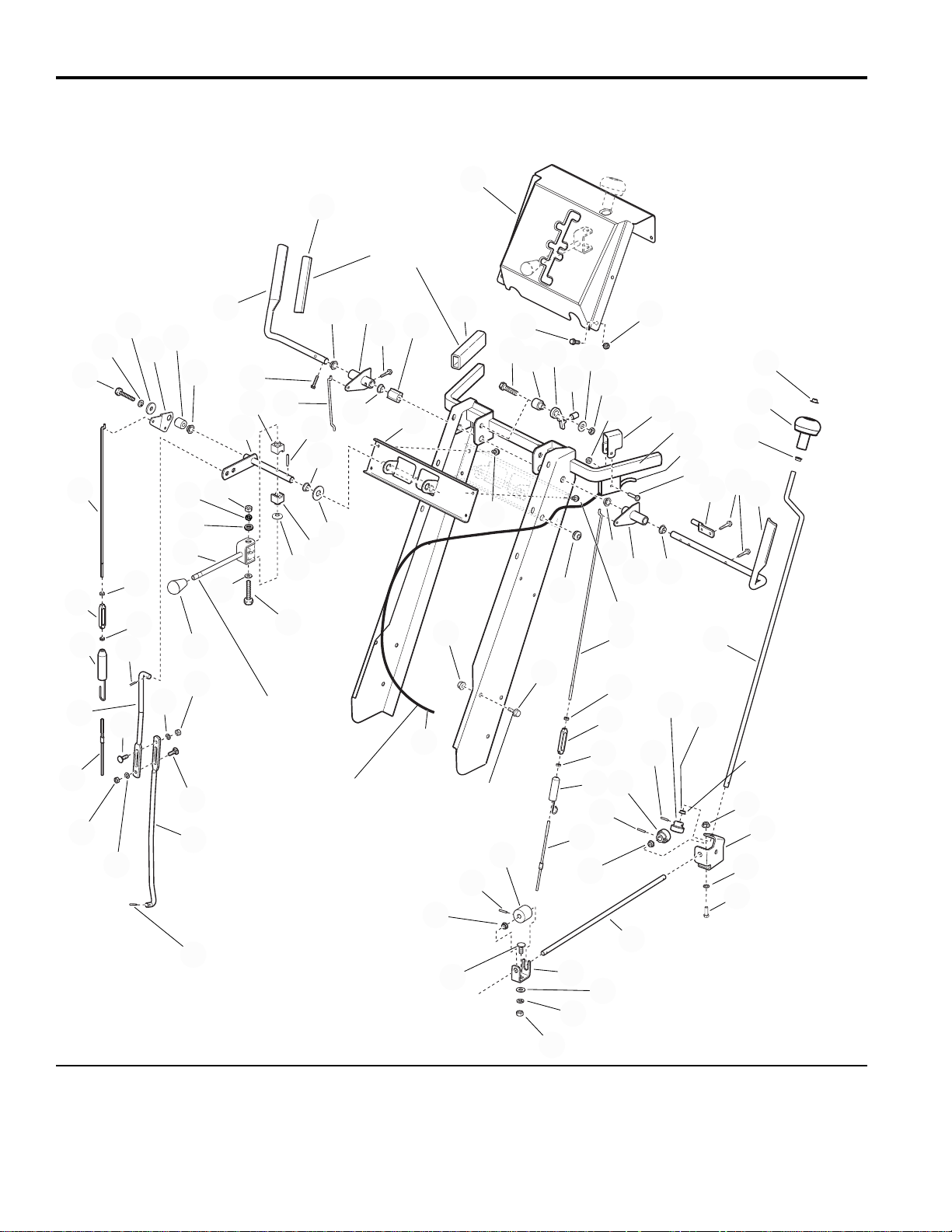
Handles and Controls Group
NOTE: Unless noted otherwise,
use the standard hardware torque
specification chart.
985643
The above parts group applies to the following Mfg. Nos.:
1693652 860DLX, 8HP Manual Start
1693653 860DLX, 8HP Manual Start (Export)
1694241 860DLXE, 8HP Electric Start
1693654 970M, 9HP Manual Start
1693655 970M, 9HP Manual Start (Export)
1694243 970E, 9HP Electrical Start
1693656 1180M, 11HP Manual Start
1693657 1180M, 11HP Manual Start (Export)
1694244 1180E, 11HP Electrical Start
© Copyright 2002 Simplicity Manufacturing, Inc. All Rights Reserved.
Linkage adjustment for traction and auger drive
with power boost: with drive levers engaged, the
bottom end of lower rods (Ref. 33 & 67) should be
flush with bottom of springs (Ref. 32 & 68).
Mount clutch cable to cable
support, see specific
Engine & Frame Grroup.
Shift rod assembly
(Ref. 54) must pivot
freely on pivot blocks
(Ref. 59).
Mount bushings
(Ref. 36) with flanges
on inside of brackets
(Ref. 41 & 48).
Torque to
19 - 29 ft-lbs.
Apply adheasive to
secure grips.
1
2
3
4
5
6
7
8
9
10
11
12
13
14
15
16
17
18
19
20
21
22
23
24
25
26
27
28
34
35
36
37
29
30
31
32
33
36
38
39
38
39
36
40
41
42
43
44
45
46
47
48
49
50
51
52
53
36
20
6
67
63
31
30
69
59
62
59
56
57
58
60
6
70
71
72
73
49
9
9
6
6
8
74
38
6
55
54
61
58
56
57
65
65
57
56
63
68
29
64
66
75
76
Page 15

11
TP 400-2307-03-LW-S
Handles and Controls Group
1 1667800 1 DASHBOARD
2 1935450 4 CAPSCREW, Hex Head, 1/4-20 x 3/4
3 1920397 4 NUT, Hex Lock, 1/4-20
4 1612165 1 HANDLE, Clutch, RH
5 1668608 2 GRIP
6 1668185 6 BUSHING, Nylon
7 1702663 1 ROD, Clutch
8 1704255 2 LEVER & TUBE ASSEMBLY, Clutch
9 1960471 4 CAPSCREW, Hex Washer Head, #12-24 x 1
10 1928732 1 CAPSCREW, Hex Washer Head, #10-24 x 1
11 1705899 1 GUIDE, Control
12 1927429 2 CAPSCREW, Hex Washer Head, 1/4-20 x 5/8
13 1668050 1 BRACKET, Shift Control
14 1925003 4 CAPSCREW, Hex Head, Taptite, 1/4-20 x 1/2
15 1671041 2 GRIP
16 1921221 1 CAPSCREW, Hex Head, 5/16-18 x 1 1/2
17 1678579 1 SPACER
18 1705898 1 LATCH, Control
19 1701342 1 SPRING, Compression
20 1919326 2 WASHER, 5/16
21 1923362 1 NUT, Hex, Center Lock, 5/16-18
22 1933896 1 NUT, Hex Lock, #10-24
23 1720747 1 CLAMP, Clutch Cable
24 1960393 1 SCREW, Pan Head, Phillips, #10-24 x 1
25 1720586 1 HANDLE ASSEMBLY
26 1677453 1 ROD, Control17.3” Long
27 1612167 1 HANDLE, Clutch
28 1668121 1 ROD
29 928704 2 NUT, LH, Machine Screw, Hex, #10-24
30 108775 2 TURNBUCKLE
31 1916621 2 NUT, RH, Machine Screw, Hex, #10-24
32 1707452 1 SPRING
33 1668526 1 ROD, Clutch
34 1960093 1 PUSH NUT
35 1714084 1 KNOB, Spinner
36 1667588 4 BUSHING, Nylon
37 1715658 1 ROD, Chute Control
38 1918452 3 PIN, Cotter
39 1718593 2 GEAR, Metal
40 1960294 2 NUT, Hex Flange, 1/4-20
41 1718793 1 SUPPORT, Gear
42 1960518 2 PUSH NUT
43 1960252 2 CARRIAGE BOLT, 1/4-20 x 5/8
44 1668187 1 ROD, Chute
45 1668186 1 GEAR, Worm
46 916168 2 PIN, Spring, 1/8 x 3/4
47 1931333 1 CARRIAGE BOLT, 5/16-18 x 3/4
48 1611911 1 SUPPORT, Worm
49 1917356 2 LOCKWASHER, Spring, 5/16
REF NO. PART NO. QTY. DESCRIPTION
Footnotes:
The above parts group applies to the following Mfg. Nos.:
1693652 860DLX, 8HP Manual Start
1693653 860DLX, 8HP Manual Start (Export)
1694241 860DLXE, 8HP Electric Start
1693654 970M, 9HP Manual Start
1693655 970M, 9HP Manual Start (Export)
1694243 970E, 9HP Electrical Start
1693656 1180M, 11HP Manual Start
1693657 1180M, 11HP Manual Start (Export)
1694244 1180E, 11HP Electrical Start
Page 16

12
TP 400-2307-03-LW-S
Handles and Controls Group
NOTE: Unless noted otherwise,
use the standard hardware torque
specification chart.
985643
Linkage adjustment for traction and auger drive
with power boost: with drive levers engaged, the
bottom end of lower rods (Ref. 33 & 67) should be
flush with bottom of springs (Ref. 32 & 68).
Mount clutch cable to cable
support, see specific
Engine & Frame Grroup.
Shift rod assembly
(Ref. 54) must pivot
freely on pivot blocks
(Ref. 59).
Mount bushings
(Ref. 36) with flanges
on inside of brackets
(Ref. 41 & 48).
Torque to
19 - 29 ft-lbs.
Apply adheasive to
secure grips.
1
2
3
4
5
6
7
8
9
10
11
12
13
14
15
16
17
18
19
20
21
22
23
24
25
26
27
28
34
35
36
37
29
30
31
32
33
36
38
39
38
39
36
40
41
42
43
44
45
46
47
48
49
50
51
52
53
36
20
6
67
63
31
30
69
59
62
59
56
57
58
60
6
70
71
72
73
49
9
9
6
6
8
74
38
6
55
54
61
58
56
57
65
65
57
56
63
68
29
64
66
75
76
The above parts group applies to the following Mfg. Nos.:
1693652 860DLX, 8HP Manual Start
1693653 860DLX, 8HP Manual Start (Export)
1694241 860DLXE, 8HP Electric Start
1693654 970M, 9HP Manual Start
1693655 970M, 9HP Manual Start (Export)
1694243 970E, 9HP Electrical Start
1693656 1180M, 11HP Manual Start
1693657 1180M, 11HP Manual Start (Export)
1694244 1180E, 11HP Electric Start
© Copyright 2002 Simplicity Manufacturing, Inc. All Rights Reserved.
Page 17

13
TP 400-2307-03-LW-S
Handles and Controls Group
50 1917372 1 NUT, Hex, 5/16-18
51 1664022 1 GROMMET
52 1930591 6 CAPSCREW, Hex Whiz Lock, 5/16-18 x 3/4
53 1718791 1 CABLE & HANDLE ASSEMBLY, Clutch (Includes Ref. 75)
54 1714120 1 SHIFT ASSEMBLY, Rod & Clevis
55 1713844 1 KNOB
56 1916622 3 NUT, Hex, 1/4-20
57 1916964 3 LOCKWASHER, Spring, 1/4
58 1921319 1 WASHER, 1/4
59 1668524 2 BLOCK, Pivot
60 1703043 1 ROD & ARM ASSEMBLY, Pivot
61 1921159 1 CAPSCREW, Hex Head, 1/4-20 x 2 1/4
62 1924361 1 WASHER, 1/2
63 1918447 3 PIN, Cotter
64 1720448 1 ROD, Shift, Upper
65 1931317 2 CARRIAGE BOLT, 1/4-20 x 3/4
66 1666255 1 ROD, Shift, Lower
67 1702004 1 ROD, Clutch, Lower
68 1701996 1 SPRING
69 1702485 1 ROD, Clutch, Upper
70 1702552 1 SPACER
71 1919381 1 WASHER, 5/16
72 1702662 1 LEVER, Clutch
73 1922127 1 CAPSCREW, Hex Head, 5/16-18 x 3/4
74 1931277 6 NUT, Hex Flange, 5/16-18
75 1718804 1 TRIGGER ASSEMBLY, Easy Turn Clutch Cable
76 1668681 1 WASHER, Curved, 1/2
REF NO. PART NO. QTY. DESCRIPTION
Footnotes:
The above parts group applies to the following Mfg. Nos.:
1693652 860DLX, 8HP Manual Start
1693653 860DLX, 8HP Manual Start (Export)
1694241 860DLXE, 8HP Electric Start
1693654 970M, 9HP Manual Start
1693655 970M, 9HP Manual Start (Export)
1694243 970E, 9HP Electrical Start
1693656 1180M, 11HP Manual Start
1693657 1180M, 11HP Manual Start (Export)
1694244 1180E, 11HP Electric Start
Page 18
14
TP 400-2307-03-LW-S
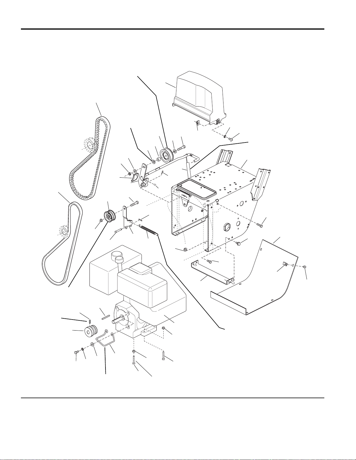
Engine & Frame Group - 8HP, Manual Start
NOTE: Unless noted otherwise,
use the standard hardware torque
specification chart.
985633
Hook one end of spring (Ref. 15)
into top hole of idler arm (Ref. 16)
and other end into top hole of the idler
arm assembly in the Traction Drive Group.
Long hub of idler pulley
(Ref. 19) to be toward
idler arm (Ref. 16).
Position idler pulley (Ref. 25)
at center of slot in clutch arm
(Ref. 22).
Hook one end of spring (Ref. 27)
over clutch rod assembly (Ref. 22)
between tabs and other end into
slot in frame.
Use 0-2 washers
between Ref. 40
& 22 to assure a
centered belt and no
interference between
pulleys Ref. 19 & 25.
Position belt stop (Ref. 33)
1/16 to 1/8 inch from belt
when auger clutch is engaged.
Torque to
10-14 ft. lbs. or
14-20 N m
Right rear bolt.
2
1
3
4
5
6
7
8
9
10
11
12
13
14
15
16
17
18
19
20
21
21
22
39
40
25
26
27
28
30
29
31
32
33
34
35
36
37
38
39
39
8
18
18
29
23
24
The above parts group applies to the following Mfg. Nos.:
1693650 860M, 8HP Manual Start
1693651 860M, 8HP Manual Start (Export)
© Copyright 2002 Simplicity Manufacturing, Inc. All Rights Reserved.
Page 19

15
TP 400-2307-03-LW-S
Engine & Frame Group - 8HP, Manual Start
1 1672732 1 BELT, Traction
2 1666655 1 BELT, Drive Auger
3 1667516 1 GUARD, Belt
4 1935255 2 NUT, Speed, 5/16-18
5 920426 2 LOCKWASHER, Ext. Tooth, 5/16
6 1918249 2 SCREW, Truss Head, 5/16-18 x 3/4
7 1720408 1 FRAME, Main
8 1930591 4 CAPSCREW, Whizlock, 5/16-18 x 3/4
9 1664847 4 CAPSCREW, Taptite, 5/16-18 x 3/8
10 1666374 1 COVER, Bottom
11 1926018 6 NUT, Speed, 1/4-20
12 1925003 6 CAPSCREW, Taptite,1/4-20 x 1/2
13 1669198 1 SUPPORT, Tie Bar
14 1927557 4 NUT, Hex, Whizlock, 5/16-18
15 1672735 1 SPRING, Idler
16 1703046 1 ARM, Idler, Traction
17 1665994 1 PIN
18 1928731 2 LOCKNUT, Jam, 3/8-16
19 1668477 1 PULLEY, Idler
20 1960647 1 CAPSCREW, Hex Head, 3/8-16 x 1-1/2
21 1918451 2 PlN, Cotter, 1/8 x 3/4
22 1612200 1 CLUTCH ROD & BRAKE ASSEMBLY
23 1669313 1 PAD, Brake
24 925160 2 RIVET, Pop
25 154534 1 PULLEY
26 1921971 1 CAPSCREW, Hex Head, 3/8-16 x 1-3/4
27 1701595 1 SPRING, Extension
28 * 1 ENGINE, Tecumseh, 8 H.P. Manual Start - Engine Model # HMSK110,
Engine Type # 155670V
29 1931277 4 NUT, Hex, 5/16-18
30 1922127 3 CAPSCREW, Hex Head, 5/16-18 x 1 3/4
31 1921978 4 CAPSCREW, Hex Head, 5/16-18 x 2
32 1668174 1 GUIDE, Belt
33 1919326 6 WASHER,11/32 x 3/4
34 1917356 2 LOCKWASHER, 5/16
35 1921515 2 CAPSCREW, Hex Head, 5/16-24 x 3/4
36 1666109 1 PULLEY, Traction
37 1930540 1 SETSCREW, .625 LG
38 8221042 1 KEY, Parallel, 3/16 x 13/16 x 7/8
39 1924940 3 WASHER, Flat,13/32
40 157081 1 SPACER
REF NO. PART NO. QTY. DESCRIPTION
Footnotes:
* See your local Tecumseh distributor for Parts and Service.
The above parts group applies to the following Mfg. Nos.:
1693650 860M, 8HP Manual Start
1693651 860M, 8HP Manual Start (Export)
Page 20
16
TP 400-2307-03-LW-S
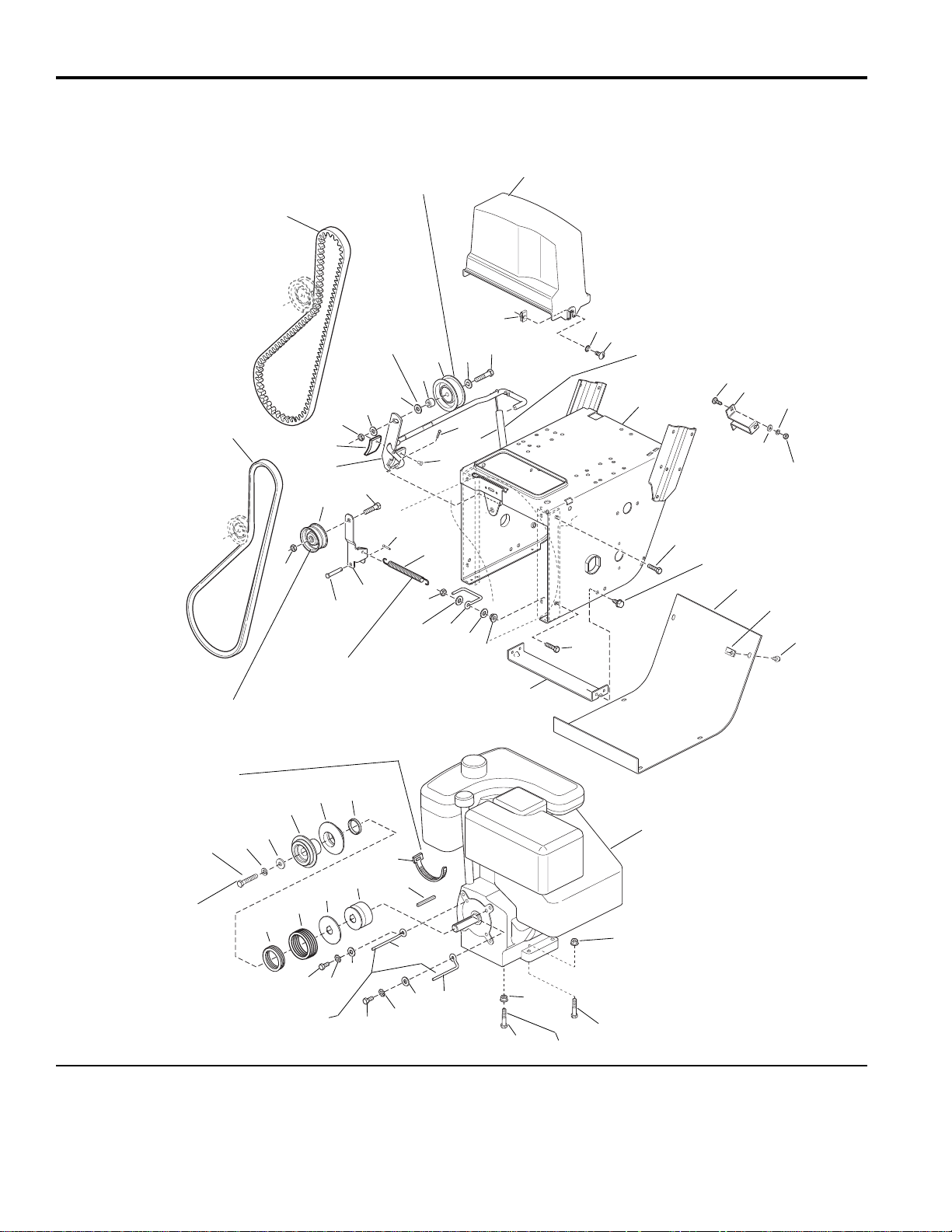
Engine & Frame Group - 8HP, Manual Start
NOTE: Unless noted otherwise,
use the standard hardware torque
specification chart.
985634
Position idler pulley (Ref. 34) at
center of slot in clutch arm (Ref. 31).
Use 0-2
washers
between
Ref. 58 & 31
to assure a
centered
belt and no
interference
between
pulleys Ref.
27 & 34.
Long hub of idler pulley
(Ref. 27) to be toward
Hook one end of spring (Ref. 24)
into top hole of idler arm (Ref. 25)
and other end into top hole of the
pilot arm assembly in the traction
Torque to
10 - 12 ft. lbs.
Secure engine lead
wire for headlight to
oil filler tube.
Hook one end of spring
(Ref. 36) over clutch rod
assembly (Ref. 31)
between tabs and other
end into slot in frame.
Right rear bolt
Position belt stop (Ref. 42)
1/16 to 1/8 inch from belt
when auger clutch is
engaged.
idler arm (Ref. 25).
drive group.
2
1
3
4
5
6
7
8
9
10
11
12
13
14
15
16
17
18
19
20
21
22
23
24
25
26
27
28
29
30
31
57
58
34
35
36
37
38
39
40
41
42
43
44
45
46
47
48
49
50
51
52
53
54
55
44
43
21
42
21
21
28
57
57
30
56
32
33
The above parts group applies to the following Mfg. Nos.:
1693652 860DLX, 8HP Manual Start
1693653 860DLX, 8HP Manual Start (Export)
© Copyright 2002 Simplicity Manufacturing, Inc. All Rights Reserved.
Page 21

17
TP 400-2307-03-LW-S
Engine & Frame Group - 8HP, Manual Start
1 1672732 1 BELT, Traction
2 1701257 1 BELT, Auger Drive
3 1667516 1 GUARD, Belt
4 1935255 2 NUT, Speed, 5/16-18
5 920426 2 LOCKWASHER, Ext. Tooth, 5/16
6 1918249 2 SCREW, Truss Head, 5/16-18 x 3/4
7 1720235 1 FRAME, Main
8 1931317 2 CARRIAGE BOLT, 1/4-20 x 3/4
9 1720404 1 SUPPORT, Clutch Cable
10 1921319 2 WASHER, 1/4
11 1916964 2 LOCKWASHER, Spring, 1/4
12 1916622 2 NUT, Hex 1/4-20
13 1930591 2 CAPSCREW, Whizlock, 5/16-18 x 3/4
14 1664847 4 CAPSCREW, Taptite, 5/16-18 x 3/8
15 1666374 1 COVER, Bottom
16 1926018 6 NUT, Speed, 1/4-20
17 1925003 6 CAPSCREW, Taptite,1/4-20 x 1/2
18 1669198 1 SUPPORT, Tie Bar
19 1930595 2 CAPSCREW, Whizlock, 5/16-18 x 1-1/4
20 1927557 4 NUT, Hex, Whizlock, 5/16-18
21 1919326 6 WASHER,11/32 x 3/4
22 1702969 2 GUIDE, Belt
23 1923362 2 NUT, Hex, Centerlock, 5/16-18
24 1672735 1 SPRING, Idler
25 1703046 1 ARM, Idler, Traction
26 1665994 1 PIN
27 1668477 1 PULLEY, Idler
28 1928731 2 LOCKNUT, Jam, 3/8-16
29 1960647 1 CAPSCREW, Hex Head, 3/8-16 x 1-1/2
30 1918451 2 PlN,Cotter,1/8 x 3/4
31 1612200 1 CLUTCH ROD & BRAKE ASSEMBLY
32 1669313 1 PAD, Brake
33 925160 2 RIVET, Pop
34 154534 1 PULLEY
35 1921971 1 CAPSCREW, Hex Head, 3/8-16 x 1-3/4
36 1701595 1 SPRING, Extension
37 * 1 ENGINE, Tecumseh, 8 H.P. Manual Start - Engine Model # OSHK80,
Engine Type # 221202A
38 1931277 3 NUT, Hex, 5/16-18, Black
39 1922127 3 CAPSCREW, Hex Head, 5/16-18 x 2, Black
40 1931277 1 NUT, Hex Flange, 5/16-18
41 1922127 1 CAPSCREW, Hex Head, 5/16-18 x 1-3/4
42 1702970 2 GUIDE, Belt
43 1917356 2 LOCKWASHER, 5/16
44 1921515 2 CAPSCREW, Hex Head, 5/16-24 x 3/4
45 1672129 1 KEY, Parallel, 3/16 x 13/16 x 7/8
46 1701783 1 PULLEY, Traction
47 1701818 1 WASHER, Thrust
48 1702425 1 SPRING, Compression
REF NO. PART NO. QTY. DESCRIPTION
Footnotes:
* See your local Tecumseh distributor for Parts and Service.
** Not a Service Part.
The above parts group applies to the following Mfg. Nos.:
1693652 860DLX, 8HP Manual Start
1693653 860DLX, 8HP Manual Start (Export)
Page 22

18
TP 400-2307-03-LW-S
Engine & Frame Group - 8HP, Manual Start
NOTE: Unless noted otherwise,
use the standard hardware torque
specification chart.
985634
The above parts group applies to the following Mfg. Nos.:
1693652 860DLX, 8HP Manual Start
1693653 860DLX, 8HP Manual Start (Export)
© Copyright 2002 Simplicity Manufacturing, Inc. All Rights Reserved.
Position idler pulley (Ref. 34) at
center of slot in clutch arm (Ref. 31).
Use 0-2
washers
between
Ref. 58 & 31
to assure a
centered
belt and no
interference
between
pulleys Ref.
27 & 34.
Long hub of idler pulley
(Ref. 27) to be toward
Hook one end of spring (Ref. 24)
into top hole of idler arm (Ref. 25)
and other end into top hole of the
pilot arm assembly in the traction
Torque to
10 - 12 ft. lbs.
Secure engine lead
wire for headlight to
oil filler tube.
Hook one end of spring
(Ref. 36) over clutch rod
assembly (Ref. 31)
between tabs and other
end into slot in frame.
Right rear bolt
Position belt stop (Ref. 42)
1/16 to 1/8 inch from belt
when auger clutch is
engaged.
idler arm (Ref. 25).
drive group.
2
1
3
4
5
6
7
8
9
10
11
12
13
14
15
16
17
18
19
20
21
22
23
24
25
26
27
28
29
30
31
57
58
34
35
36
37
38
39
40
41
42
43
44
45
46
47
48
49
50
51
52
53
54
55
44
43
21
42
21
21
28
57
57
30
56
32
33
Page 23

19
TP 400-2307-03-LW-S
Engine & Frame Group - 8HP, Manual Start
49 1702979 1 SPRING, Compression
50 ** 1 WICK, Oil
51 1702017 1 PULLEY, Drive
52 1701776 1 PULLEY, Drive
53 1922755 1 WASHER,13/32 x 1
54 1916965 1 LOCKWASHER, Spring, 3/8
55 1960345 1 CAPSCREW, Hex Head, 3/8-24 x 2
56 1701011 1 TIE, Self Locking
57 1924940 3 WASHER, Flat,13/32
58 157081 1 SPACER
REF NO. PART NO. QTY. DESCRIPTION
Footnotes:
* See your local Tecumseh distributor for Parts and Service.
** Not a Service Part.
The above parts group applies to the following Mfg. Nos.:
1693652 860DLX, 8HP Manual Start
1693653 860DLX, 8HP Manual Start (Export)
Page 24
20
TP 400-2307-03-LW-S
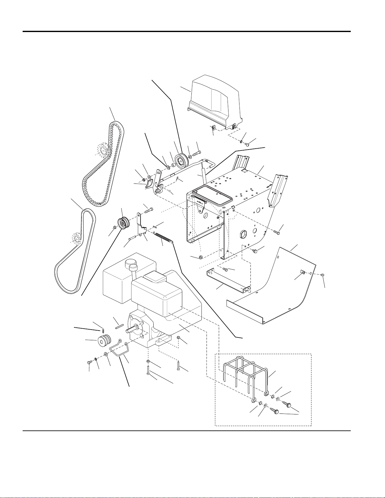
Engine & Frame Group - 8HP, Manual Start
NOTE: Unless noted otherwise,
use the standard hardware torque
specification chart.
985773
Export Only
Hook one end of spring (Ref. 15)
into top hole of roller arm (Ref. 16)
and other end into top hole of the idler
arm assembly in the Traction Drive Group.
Long hub of idler pulley
(Ref. 19) to be toward
idler arm (Ref. 16).
Position idler pulley (Ref. 25)
at center of slot in clutch arm
(Ref. 22).
Hook one end of spring (Ref. 27)
over clutch rod assembly (Ref. 22)
between tabs and other end into
slot in frame.
Use 0-2 washers
between Ref. 40
& 22 to assure a
centered belt and no
interference between
pulleys Ref. 19 & 25.
Position belt stop (Ref. 33)
1/16 to 1/8 inch from belt
when auger clutch is engaged.
Torque to
10-14 ft. lbs. or
14-20 N m
Right rear bolt.
2
1
3
4
5
6
7
8
9
10
11
12
13
14
15
16
17
18
19
20
21
21
22
39
40
25
26
27
28
30
29
31
32
33
34
35
36
37
38
39
39
8
18
18
29
23
24
44
42
42
43
43
41
44
The above parts group applies to the following Mfg. Nos.:
1693763 860M, 8HP Manual Start
1693775 860M, 8HP Manual Start (Export)
1693984 860M, 8HP Manual Start
1693985 860M, 8HP Manual Start (Export)
© Copyright 2002 Simplicity Manufacturing, Inc. All Rights Reserved.
Page 25

21
TP 400-2307-03-LW-S
Engine & Frame Group - 8HP, Manual Start
1 1672732 1 BELT, Traction
2 1666655 1 BELT, Drive Auger
3 1667516 1 GUARD, Belt
4 1935255 2 NUT, Speed, 5/16-18
5 920426 2 LOCKWASHER, Ext. Tooth, 5/16
6 1918249 2 SCREW, Truss Head, 5/16-18 x 3/4
7 1721560 1 FRAME, Main
8 1930591 4 CAPSCREW, Whizlock, 5/16-18 x 3/4
9 1664847 4 CAPSCREW, Taptite, 5/16-18 x 3/8
10 1666374 1 COVER, Bottom
11 1926018 6 NUT, Speed, 1/4-20
12 1925003 6 CAPSCREW, Taptite,1/4-20 x 1/2
13 1669198 1 SUPPORT, Tie Bar
14 1927557 4 NUT, Hex, Whizlock, 5/16-18
15 1672735 1 SPRING, Idler
16 1703046 1 ARM, Idler, Traction
17 1665994 1 PIN
18 1928731 2 LOCKNUT, Jam, 3/8-16
19 1668477 1 PULLEY, Idler
20 1960647 1 CAPSCREW, Hex Head, 3/8-16 x 1-1/2
21 1918451 2 PlN, Cotter, 1/8 x 3/4
22 1612200 1 CLUTCH ROD & BRAKE ASSEMBLY
23 1669313 1 PAD, Brake
24 925160 2 RIVET, Pop
25 154534 1 PULLEY
26 1921971 1 CAPSCREW, Hex Head, 3/8-16 x 1-3/4
27 1701595 1 SPRING, Extension
28 * 1 ENGINE, Tecumseh, 8 H.P. Manual Start - Engine Model # HMSK110,
Engine Type # 155670V
29 1931277 4 NUT, Hex, 5/16-18
30 1922127 3 CAPSCREW, Hex Head, 5/16-18 x 1 3/4
31 1921978 4 CAPSCREW, Hex Head, 5/16-18 x 2
32 1668174 1 GUIDE, Belt
33 1919326 6 WASHER,11/32 x 3/4
34 1917356 2 LOCKWASHER, 5/16
35 1921515 2 CAPSCREW, Hex Head, 5/16-24 x 3/4
36 1666109 1 PULLEY, Traction
37 1930540 1 SETSCREW, .625 LG
38 8221042 1 KEY, Parallel, 3/16 x 13/16 x 7/8
39 1924940 3 WASHER, Flat,13/32
40 157081 1 SPACER
41 1720878 1 GUARD, Wire Muffler Sheild (Export Only)
42 1917365 1 LOCKWASHER, Spring 3/16 (Export Only)
43 1910531 1 WASHER, Rivet 3/16 (Export Only)
44 1720879 1 CAPSCREW, Hex Washer Head, Self Tap (Export Only)
REF NO. PART NO. QTY. DESCRIPTION
Footnotes:
* See your local Tecumseh distributor for Parts and Service.
The above parts group applies to the following Mfg. Nos.:
1693763 860M, 8HP Manual Start
1693775 860M, 8HP Manual Start (Export)
1693984 860M, 8HP Manual Start
1693985 860M, 8HP Manual Start (Export)
Page 26
22
TP 400-2307-03-LW-S
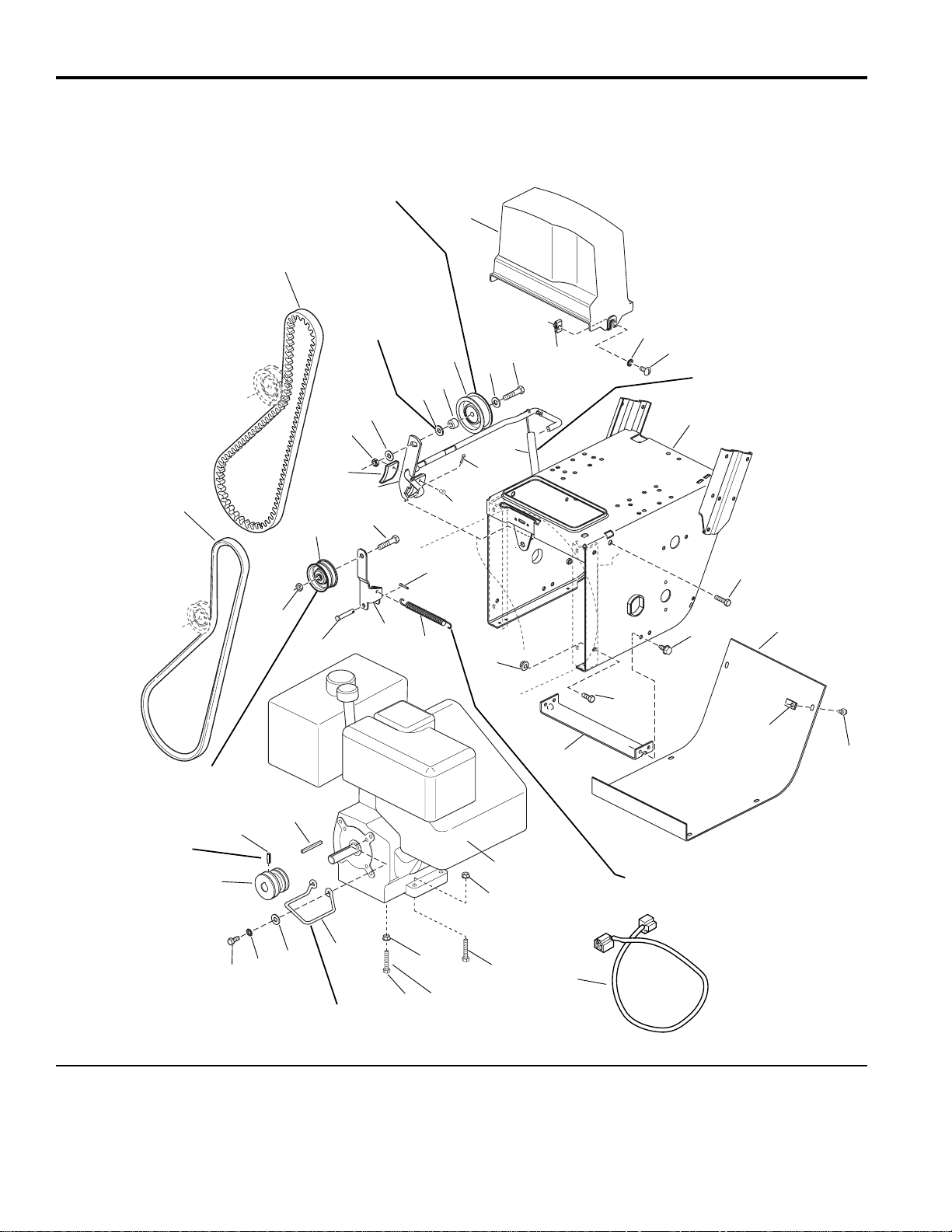
Engine & Frame Group - 8HP, Electric Start
NOTE: Unless noted otherwise,
use the standard hardware torque
specification chart.
986111
Hook one end of spring (Ref. 15)
into top hole of roller arm (Ref. 16)
and other end into top hole of the idler
arm assembly in the Traction Drive Group.
Long hub of idler pulley
(Ref. 19) to be toward
idler arm (Ref. 16).
Position idler pulley (Ref. 25)
at center of slot in clutch arm
(Ref. 22).
Hook one end of spring (Ref. 27)
over clutch rod assembly (Ref. 22)
between tabs and other end into
slot in frame.
Use 0-2 washers
between Ref. 40
& 22 to assure a
centered belt and no
interference between
pulleys Ref. 19 & 25.
Position belt stop (Ref. 33)
1/16 to 1/8 inch from belt
when auger clutch is engaged.
Torque to
10-14 ft. lbs. or
14-20 N m
Right rear bolt.
2
1
3
4
5
6
7
8
9
10
11
12
13
14
15
16
17
18
19
20
21
21
22
39
40
25
26
27
28
30
29
31
32
33
34
35
36
37
38
39
39
8
18
18
29
23
24
41
The above parts group applies to the following Mfg. Nos.:
1694242 860E, 8HP Electric Start
© Copyright 2002 Simplicity Manufacturing, Inc. All Rights Reserved.
Page 27

23
TP 400-2307-03-LW-S
Engine & Frame Group - 8HP, Electric Start
1 1672732 1 BELT, Traction
2 1666655 1 BELT, Drive Auger
3 1667516 1 GUARD, Belt
4 1935255 2 NUT, Speed, 5/16-18
5 920426 2 LOCKWASHER, Ext. Tooth, 5/16
6 1918249 2 SCREW, Truss Head, 5/16-18 x 3/4
7 1721560 1 FRAME, Main
8 1930591 4 CAPSCREW, Whizlock, 5/16-18 x 3/4
9 1664847 4 CAPSCREW, Taptite, 5/16-18 x 3/8
10 1666374 1 COVER, Bottom
11 1926018 6 NUT, Speed, 1/4-20
12 1925003 6 CAPSCREW, Taptite,1/4-20 x 1/2
13 1669198 1 SUPPORT, Tie Bar
14 1927557 4 NUT, Hex, Whizlock, 5/16-18
15 1672735 1 SPRING, Idler
16 1703046 1 ARM, Idler, Traction
17 1665994 1 PIN
18 1928731 2 LOCKNUT, Jam, 3/8-16
19 1668477 1 PULLEY, Idler
20 1960647 1 CAPSCREW, Hex Head, 3/8-16 x 1-1/2
21 1918451 2 PlN, Cotter, 1/8 x 3/4
22 1612200 1 CLUTCH ROD & BRAKE ASSEMBLY
23 1669313 1 PAD, Brake
24 925160 2 RIVET, Pop
25 154534 1 PULLEY
26 1921971 1 CAPSCREW, Hex Head, 3/8-16 x 1-3/4
27 1701595 1 SPRING, Extension
28 * 1 ENGINE, Tecumseh, 8 H.P. Electric Start - Engine Model # HMSK80,
Engine Type # 155670W
29 1931277 4 NUT, Hex, 5/16-18
30 1922127 3 CAPSCREW, Hex Head, 5/16-18 x 1-3/4
31 1921978 4 CAPSCREW, Hex Head, 5/16-18 x 2
32 1668174 1 GUIDE, Belt
33 1919326 6 WASHER,11/32 x 3/4
34 1917356 2 LOCKWASHER, 5/16
35 1921515 2 CAPSCREW, Hex Head, 5/16-24 x 3/4
36 1666109 1 PULLEY, Traction
37 1930540 1 SETSCREW, .625 LG
38 8221042 1 KEY, Parallel, 3/16 x 13/16 x 7/8
39 1924940 3 WASHER, Flat,13/32
40 157081 1 SPACER
41 1717432 1 CORD, Electrical, 3 Prong
REF NO. PART NO. QTY. DESCRIPTION
Footnotes:
* See your local Tecumseh distributor for Parts and Service.
The above parts group applies to the following Mfg. Nos.:
1694242 860E, 8HP Electric Start
Page 28

24
TP 400-2307-03-LW-S
Engine & Frame Group - 8HP, Electric Start
NOTE: Unless noted otherwise,
use the standard hardware torque
specification chart.
986095
Position idler pulley (Ref. 34) at
center of slot in clutch arm (Ref. 31).
Use 0-2
washers
between
Ref. 58 & 31
to assure a
centered
belt and no
interference
between
pulleys Ref.
27 & 34.
Long hub of idler pulley
(Ref. 27) to be toward
Hook one end of spring (Ref. 24)
into top hole of idler arm (Ref. 25)
and other end into top hole of the
pilot arm assembly in the Traction
Torque to
10 - 12 ft. lbs.
Secure engine lead
wire for headlight to
oil filler tube.
Hook one end of spring
(Ref. 36) over clutch rod
assembly (Ref. 31)
between tabs and other
end into slot in frame.
Right rear bolt
Position belt stop (Ref. 42)
1/16 to 1/8 inch from belt
when auger clutch is
engaged.
Drive Group.
idler arm (Ref. 25).
2
1
3
4
5
6
7
8
9
10
11
12
13
14
15
16
17
18
19
20
21
22
23
24
25
26
27
28
29
30
31
57
58
34
35
36
37
38
39
40
41
42
43
44
45
46
47
48
49
50
51
52
53
54
55
44
43
21
42
21
21
28
57
57
30
56
32
33
59
The above parts group applies to the following Mfg. Nos.:
1694241 860DLXE, 8HP Electric Start
© Copyright 2002 Simplicity Manufacturing, Inc. All Rights Reserved.
Page 29

25
TP 400-2307-03-LW-S
Engine & Frame Group - 8HP, Electric Start
1 1672732 1 BELT, Traction
2 1701257 1 BELT, Auger Drive
3 1667516 1 GUARD, Belt
4 1935255 2 NUT, Speed, 5/16-18
5 920426 2 LOCKWASHER, Ext. Tooth, 5/16
6 1918249 2 SCREW, Truss Head, 5/16-18 x 3/4
7 1720235 1 FRAME, Main
8 1931317 2 CARRIAGE BOLT, 1/4-20 x 3/4
9 1720404 1 SUPPORT, Clutch Cable
10 1921319 2 WASHER, 1/4
11 1916964 2 LOCKWASHER, Spring, 1/4
12 1916622 2 NUT, Hex 1/4-20
13 1930591 2 CAPSCREW, Whizlock, 5/16-18 x 3/4
14 1664847 4 CAPSCREW, Taptite, 5/16-18 x 3/8
15 1666374 1 COVER, Bottom
16 1926018 6 NUT, Speed, 1/4-20
17 1925003 6 CAPSCREW, Taptite,1/4-20 x 1/2
18 1669198 1 SUPPORT, Tie Bar
19 1930595 2 CAPSCREW, Whizlock, 5/16-18 x 1-1/4
20 1927557 4 NUT, Hex, Whizlock, 5/16-18
21 1919326 6 WASHER,11/32 x 3/4
22 1702969 2 GUIDE, Belt
23 1923362 2 NUT, Hex, Centerlock, 5/16-18
24 1672735 1 SPRING, Idler
25 1703046 1 ARM, Idler, Traction
26 1665994 1 PIN
27 1668477 1 PULLEY, Idler
28 1928731 2 LOCKNUT, Jam, 3/8-16
29 1960647 1 CAPSCREW, Hex Head, 3/8-16 x 1-1/2
30 1918451 2 PlN,Cotter,1/8 x 3/4
31 1612200 1 CLUTCH ROD & BRAKE ASSEMBLY
32 1669313 1 PAD, Brake
33 925160 2 RIVET, Pop
34 154534 1 PULLEY
35 1921971 1 CAPSCREW, Hex Head, 3/8-16 x 1-3/4
36 1701595 1 SPRING, Extension
37 * 1 ENGINE, Tecumseh, 8 H.P. Electric Start - Engine Model # OSHK80,
Engine Type # 221202A
38 1931277 3 NUT, Hex, 5/16-18, Black
39 1922127 3 CAPSCREW, Hex Head, 5/16-18 x 2, Black
40 1931277 1 NUT, Hex Flange, 5/16-18
41 1922127 1 CAPSCREW, Hex Head, 5/16-18 x 1-3/4
42 1702970 2 GUIDE, Belt
43 1917356 2 LOCKWASHER, 5/16
44 1921515 2 CAPSCREW, Hex Head, 5/16-24 x 3/4
45 1672129 1 KEY, Parallel, 3/16 x 13/16 x 7/8
46 1701783 1 PULLEY, Traction
47 1701818 1 WASHER, Thrust
48 1702425 1 SPRING, Compression
REF NO. PART NO. QTY. DESCRIPTION
Footnotes:
* See your local Tecumseh distributor for Parts and Service.
** Not a Service Part.
The above parts group applies to the following Mfg. Nos.:
1694241 860DLXE, 8HP Electric Start
Page 30

26
TP 400-2307-03-LW-S
Engine & Frame Group - 8HP, Electric Start
NOTE: Unless noted otherwise,
use the standard hardware torque
specification chart.
986095
The above parts group applies to the following Mfg. Nos.:
1694241 860DLXE, 8HP Electric Start
© Copyright 2002 Simplicity Manufacturing, Inc. All Rights Reserved.
Position idler pulley (Ref. 34) at
center of slot in clutch arm (Ref. 31).
Use 0-2
washers
between
Ref. 58 & 31
to assure a
centered
belt and no
interference
between
pulleys Ref.
27 & 34.
Long hub of idler pulley
(Ref. 27) to be toward
Hook one end of spring (Ref. 24)
into top hole of idler arm (Ref. 25)
and other end into top hole of the
pilot arm assembly in the Traction
Torque to
10 - 12 ft. lbs.
Secure engine lead
wire for headlight to
oil filler tube.
Hook one end of spring
(Ref. 36) over clutch rod
assembly (Ref. 31)
between tabs and other
end into slot in frame.
Right rear bolt
Position belt stop (Ref. 42)
1/16 to 1/8 inch from belt
when auger clutch is
engaged.
Drive Group.
idler arm (Ref. 25).
2
1
3
4
5
6
7
8
9
10
11
12
13
14
15
16
17
18
19
20
21
22
23
24
25
26
27
28
29
30
31
57
58
34
35
36
37
38
39
40
41
42
43
44
45
46
47
48
49
50
51
52
53
54
55
44
43
21
42
21
21
28
57
57
30
56
32
33
59
Page 31

27
TP 400-2307-03-LW-S
Engine & Frame Group - 8HP, Electric Start
49 1702979 1 SPRING, Compression
50 ** 1 WICK, Oil
51 1702017 1 PULLEY, Drive
52 1701776 1 PULLEY, Drive
53 1922755 1 WASHER,13/32 x 1
54 1916965 1 LOCKWASHER, Spring, 3/8
55 1960345 1 CAPSCREW, Hex Head, 3/8-24 x 2
56 1701011 1 TIE, Self Locking
57 1924940 3 WASHER, Flat,13/32
58 157081 1 SPACER
59 1717432 1 CORD, Electric, 3 Prong
REF NO. PART NO. QTY. DESCRIPTION
Footnotes:
* See your local Tecumseh distributor for Parts and Service.
** Not a Service Part.
The above parts group applies to the following Mfg. Nos.:
1694241 860DLXE, 8HP Electric Start
Page 32

28
TP 400-2307-03-LW-S
Engine & Frame Group - 9HP, Manual Start
NOTE: Unless noted otherwise,
use the standard hardware torque
specification chart.
985635
Position idler pulley (Ref. 34) at
center of slot in clutch arm (Ref. 31).
Use 0-2
washers
between
Ref. 58 & 31
to assure a
centered
belt and no
interference
between
pulleys Ref.
27 & 34.
Long hub of idler pulley
(Ref. 27) to be toward
Hook one end of spring (Ref. 24)
into top hole of idler arm (Ref. 25)
and other end into top hole of the
pilot arm assembly in the Traction
Torque to
10 - 12 ft. lbs.
14 - 19 Nm.
Secure engine lead
wire for headlight to
oil filler tube.
Hook one end of spring
(Ref. 36) over clutch rod
assembly (Ref. 31)
between tabs and other
end into slot in frame.
Right rear bolt
Position belt stop (Ref. 42)
1/16 to 1/8 inch from belt
when auger clutch is
engaged.
Drive Group.
idler arm (Ref. 25).
2
1
3
4
5
6
7
8
9
10
11
12
13
14
15
16
17
18
19
20
21
22
23
24
25
26
27
28
29
30
31
57
58
34
35
36
37
38
39
40
41
42
43
44
45
46
47
48
49
50
51
52
53
54
55
44
43
21
42
21
21
28
57
57
30
56
32
33
The above parts group applies to the following Mfg. Nos.:
1693654 970M, 9HP Manual Start
1693655 970M, 9HP Manual Start (Export)
© Copyright 2002 Simplicity Manufacturing, Inc. All Rights Reserved.
Page 33

29
TP 400-2307-03-LW-S
Engine & Frame Group - 9HP, Manual Start
1 1672732 1 BELT, Traction
2 1701257 1 BELT, Auger Drive
3 1667516 1 GUARD, Belt
4 1935255 2 NUT, Speed, 5/16-18
5 920426 2 LOCKWASHER, Ext. Tooth, 5/16
6 1918249 2 SCREW, Truss Head, 5/16-18 x 3/4
7 1720235 1 FRAME, Main
8 1931317 2 CARRIAGE BOLT, 1/4-20 x 3/4
9 1720404 1 SUPPORT, Clutch Cable
10 1921319 2 WASHER, 1/4
11 1916964 2 LOCKWASHER, Spring, 1/4
12 1916622 2 NUT, Hex 1/4-20
13 1930591 2 CAPSCREW, Whizlock, 5/16-18 x 3/4
14 1664847 4 CAPSCREW, Taptite, 5/16-18 x 3/8
15 1666374 1 COVER, Bottom
16 1926018 6 NUT, Speed, 1/4-20
17 1925003 6 CAPSCREW, Taptite,1/4-20 x 1/2
18 1669198 1 SUPPORT, Tie Bar
19 1930595 2 CAPSCREW, Whizlock, 5/16-18 x 1-1/4
20 1927557 4 NUT, Hex, Whizlock, 5/16-18
21 1919326 6 WASHER,11/32 x 3/4
22 1702969 2 GUIDE, Belt
23 1923362 2 NUT, Hex, Centerlock, 5/16-18
24 1672735 1 SPRING, Idler
25 1703046 1 ARM, Idler, Traction
26 1665994 1 PIN
27 1668477 1 PULLEY, Idler
28 1928731 2 LOCKNUT, Jam, 3/8-16
29 1960647 1 CAPSCREW, Hex Head, 3/8-16 x 1-1/2
30 1918451 2 PlN,Cotter,1/8 x 3/4
31 1612200 1 CLUTCH ROD & BRAKE ASSEMBLY
32 1669313 1 PAD, Brake
33 925160 2 RIVET, Pop
34 154534 1 PULLEY
35 1921971 1 CAPSCREW, Hex Head, 3/8-16 x 1-3/4
36 1701595 1 SPRING, Extension
37 * 1 ENGINE, Tecumseh, 9 H.P. Manual Start - Engine Model # OSHK90,
Engine Type # 221408A
38 1931277 3 NUT, Hex, 5/16-18, Black
39 1922127 3 CAPSCREW, Hex Head, 5/16-18 x 2, Black
40 1931277 1 NUT, Hex Flange, 5/16-18
41 1921978 1 CAPSCREW, Hex Head, 5/16-18 x 2
42 1702970 2 GUIDE, Belt
43 1917356 2 LOCKWASHER, 5/16
44 1921515 2 CAPSCREW, Hex Head, 5/16-24 x 3/4
45 1672129 1 KEY, Parallel, 3/16 x 13/16 x 7/8
46 1701783 1 PULLEY, Traction
47 1701818 1 WASHER, Thrust
48 1702425 1 SPRING, Compression
REF NO. PART NO. QTY. DESCRIPTION
Footnotes:
* See your local Tecumseh distributor for Parts and Service.
** Not a Service Part.
The above parts group applies to the following Mfg. Nos.:
1693654 970M, 9HP Manual Start
1693655 970M, 9HP Manual Start (Export)
Page 34

30
TP 400-2307-03-LW-S
Engine & Frame Group - 9HP, Manual Start
NOTE: Unless noted otherwise,
use the standard hardware torque
specification chart.
985635
The above parts group applies to the following Mfg. Nos.:
1693654 970M, 9HP Manual Start
1693655 970M, 9HP Manual Start (Export)
© Copyright 2002 Simplicity Manufacturing, Inc. All Rights Reserved.
Position idler pulley (Ref. 34) at
center of slot in clutch arm (Ref. 31).
Use 0-2
washers
between
Ref. 58 & 31
to assure a
centered
belt and no
interference
between
pulleys Ref.
27 & 34.
Long hub of idler pulley
(Ref. 27) to be toward
Hook one end of spring (Ref. 24)
into top hole of idler arm (Ref. 25)
and other end into top hole of the
pilot arm assembly in the Traction
Torque to
10 - 12 ft. lbs.
14 - 19 Nm.
Secure engine lead
wire for headlight to
oil filler tube.
Hook one end of spring
(Ref. 36) over clutch rod
assembly (Ref. 31)
between tabs and other
end into slot in frame.
Right rear bolt
Position belt stop (Ref. 42)
1/16 to 1/8 inch from belt
when auger clutch is
engaged.
Drive Group.
idler arm (Ref. 25).
2
1
3
4
5
6
7
8
9
10
11
12
13
14
15
16
17
18
19
20
21
22
23
24
25
26
27
28
29
30
31
57
58
34
35
36
37
38
39
40
41
42
43
44
45
46
47
48
49
50
51
52
53
54
55
44
43
21
42
21
21
28
57
57
30
56
32
33
Page 35

31
TP 400-2307-03-LW-S
Engine & Frame Group - 9HP, Manual Start
49 1702979 1 SPRING, Compression
50 ** 1 WICK, Oil
51 1702017 1 PULLEY, Drive
52 1701776 1 PULLEY, Drive
53 1922755 1 WASHER,13/32 x 1
54 1916965 1 LOCKWASHER, Spring, 3/8
55 1960345 1 CAPSCREW, Hex Head, 3/8-24 x 2
56 1701011 1 TIE, Self Locking
57 1924940 3 WASHER, Flat,13/32
58 157081 1 SPACER
REF NO. PART NO. QTY. DESCRIPTION
Footnotes:
* See your local Tecumseh distributor for Parts and Service.
** Not a Service Part.
The above parts group applies to the following Mfg. Nos.:
1693654 970M, 9HP Manual Start
1693655 970M, 9HP Manual Start (Export)
Page 36

32
TP 400-2307-03-LW-S
Engine & Frame Group - 9HP, Electric Start
NOTE: Unless noted otherwise,
use the standard hardware torque
specification chart.
986098
Position idler pulley (Ref. 34) at
center of slot in clutch arm (Ref. 31).
Use 0-2
washers
between
Ref. 58 & 31
to assure a
centered
belt and no
interference
between
pulleys Ref.
27 & 34.
Long hub of idler pulley
(Ref. 27) to be toward
Hook one end of spring (Ref. 24)
into top hole of idler arm (Ref. 25)
and other end into top hole of the
pilot arm assembly in the Traction
Torque to
10 - 12 ft. lbs.
14 - 19 Nm.
Secure engine lead
wire for headlight to
oil filler tube.
Hook one end of spring
(Ref. 36) over clutch rod
assembly (Ref. 31)
between tabs and other
end into slot in frame.
Right rear bolt
Position belt stop (Ref. 42)
1/16 to 1/8 inch from belt
when auger clutch is
engaged.
Drive Group.
idler arm (Ref. 25).
2
1
3
4
5
6
7
8
9
10
11
12
13
14
15
16
17
18
19
20
21
22
23
24
25
26
27
28
29
30
31
57
58
34
35
36
37
38
39
40
41
42
43
44
45
46
47
48
49
50
51
52
53
54
55
44
43
21
42
21
21
28
57
57
30
56
32
33
59
The above parts group applies to the following Mfg. Nos.:
1694243 970E, 9HP Electrical Start
© Copyright 2002 Simplicity Manufacturing, Inc. All Rights Reserved.
Page 37

33
TP 400-2307-03-LW-S
Engine & Frame Group - 9HP, Electric Start
1 1672732 1 BELT, Traction
2 1701257 1 BELT, Auger Drive
3 1667516 1 GUARD, Belt
4 1935255 2 NUT, Speed, 5/16-18
5 920426 2 LOCKWASHER, Ext. Tooth, 5/16
6 1918249 2 SCREW, Truss Head, 5/16-18 x 3/4
7 1720235 1 FRAME, Main
8 1931317 2 CARRIAGE BOLT, 1/4-20 x 3/4
9 1720404 1 SUPPORT, Clutch Cable
10 1921319 2 WASHER, 1/4
11 1916964 2 LOCKWASHER, Spring, 1/4
12 1916622 2 NUT, Hex 1/4-20
13 1930591 2 CAPSCREW, Whizlock, 5/16-18 x 3/4
14 1664847 4 CAPSCREW, Taptite, 5/16-18 x 3/8
15 1666374 1 COVER, Bottom
16 1926018 6 NUT, Speed, 1/4-20
17 1925003 6 CAPSCREW, Taptite,1/4-20 x 1/2
18 1669198 1 SUPPORT, Tie Bar
19 1930595 2 CAPSCREW, Whizlock, 5/16-18 x 1-1/4
20 1927557 4 NUT, Hex, Whizlock, 5/16-18
21 1919326 6 WASHER,11/32 x 3/4
22 1702969 2 GUIDE, Belt
23 1923362 2 NUT, Hex, Centerlock, 5/16-18
24 1672735 1 SPRING, Idler
25 1703046 1 ARM, Idler, Traction
26 1665994 1 PIN
27 1668477 1 PULLEY, Idler
28 1928731 2 LOCKNUT, Jam, 3/8-16
29 1960647 1 CAPSCREW, Hex Head, 3/8-16 x 1-1/2
30 1918451 2 PlN,Cotter,1/8 x 3/4
31 1612200 1 CLUTCH ROD & BRAKE ASSEMBLY
32 1669313 1 PAD, Brake
33 925160 2 RIVET, Pop
34 154534 1 PULLEY
35 1921971 1 CAPSCREW, Hex Head, 3/8-16 x 1-3/4
36 1701595 1 SPRING, Extension
37 * 1 ENGINE, Tecumseh, 9 H.P. Electric Start - Engine Model # OSHK90,
Engine Type # 221408A
38 1931277 3 NUT, Hex, 5/16-18, Black
39 1922127 3 CAPSCREW, Hex Head, 5/16-18 x 2, Black
40 1931277 1 NUT, Hex Flange, 5/16-18
41 1921978 1 CAPSCREW, Hex Head, 5/16-18 x 2
42 1702970 2 GUIDE, Belt
43 1917356 2 LOCKWASHER, 5/16
44 1921515 2 CAPSCREW, Hex Head, 5/16-24 x 3/4
45 1672129 1 KEY, Parallel, 3/16 x 13/16 x 7/8
46 1701783 1 PULLEY, Traction
47 1701818 1 WASHER, Thrust
48 1702425 1 SPRING, Compression
REF NO. PART NO. QTY. DESCRIPTION
Footnotes:
* See your local Tecumseh distributor for Parts and Service.
** Not a Service Part.
The above parts group applies to the following Mfg. Nos.:
1694243 970E, 9HP Electrical Start
Page 38

34
TP 400-2307-03-LW-S
Engine & Frame Group - 9HP, Electric Start
NOTE: Unless noted otherwise,
use the standard hardware torque
specification chart.
986098
The above parts group applies to the following Mfg. Nos.:
1694243 970E, 9HP Electrical Start
© Copyright 2002 Simplicity Manufacturing, Inc. All Rights Reserved.
Position idler pulley (Ref. 34) at
center of slot in clutch arm (Ref. 31).
Use 0-2
washers
between
Ref. 58 & 31
to assure a
centered
belt and no
interference
between
pulleys Ref.
27 & 34.
Long hub of idler pulley
(Ref. 27) to be toward
Hook one end of spring (Ref. 24)
into top hole of idler arm (Ref. 25)
and other end into top hole of the
pilot arm assembly in the Traction
Torque to
10 - 12 ft. lbs.
14 - 19 Nm.
Secure engine lead
wire for headlight to
oil filler tube.
Hook one end of spring
(Ref. 36) over clutch rod
assembly (Ref. 31)
between tabs and other
end into slot in frame.
Right rear bolt
Position belt stop (Ref. 42)
1/16 to 1/8 inch from belt
when auger clutch is
engaged.
Drive Group.
idler arm (Ref. 25).
2
1
3
4
5
6
7
8
9
10
11
12
13
14
15
16
17
18
19
20
21
22
23
24
25
26
27
28
29
30
31
57
58
34
35
36
37
38
39
40
41
42
43
44
45
46
47
48
49
50
51
52
53
54
55
44
43
21
42
21
21
28
57
57
30
56
32
33
59
Page 39

35
TP 400-2307-03-LW-S
Engine & Frame Group - 9HP, Electric Start
49 1702979 1 SPRING, Compression
50 ** 1 WICK, Oil
51 1702017 1 PULLEY, Drive
52 1701776 1 PULLEY, Drive
53 1922755 1 WASHER,13/32 x 1
54 1916965 1 LOCKWASHER, Spring, 3/8
55 1960345 1 CAPSCREW, Hex Head, 3/8-24 x 2
56 1701011 1 TIE, Self Locking
57 1924940 3 WASHER, Flat,13/32
58 157081 1 SPACER
59 1717432 1 CORD, Electric, 3 Prong
REF NO. PART NO. QTY. DESCRIPTION
Footnotes:
* See your local Tecumseh distributor for Parts and Service.
** Not a Service Part.
The above parts group applies to the following Mfg. Nos.:
1694243 970E, 9HP Electrical Start
Page 40

36
TP 400-2307-03-LW-S
Engine & Frame Group - 11HP, Manual Start
NOTE: Unless noted otherwise,
use the standard hardware torque
specification chart.
985636
Position idler pulley (Ref. 34) at
center of slot in clutch arm (Ref. 31).
Use 0-2
washers
between
Ref. 58 & 31
to assure a
centered
belt and no
interference
between
pulleys Ref.
27 & 34.
Long hub of idler pulley
(Ref. 27) to be toward
Hook one end of spring (Ref. 24)
into top hole of idler arm (Ref. 25)
and other end into top hole of the
pilot arm assembly in the Traction
Torque to
10 - 12 ft. lbs.
14 - 19 Nm.
Secure engine lead
wire for headlight to
oil filler tube.
Hook one end of spring
(Ref. 36) over clutch rod
assembly (Ref. 31)
between tabs and other
end into slot in frame.
Right rear bolt
Position belt stop (Ref. 42)
1/16 to 1/8 inch from belt
when auger clutch is
engaged.
Drive Group.
idler arm (Ref. 25).
2
1
3
4
5
6
7
8
9
10
11
12
13
14
15
16
17
18
19
20
21
22
23
24
25
26
27
28
29
30
31
57
58
34
35
36
37
38
39
40
41
42
43
44
45
46
47
48
49
50
51
52
53
54
55
44
43
21
42
21
21
28
57
57
30
56
32
33
The above parts group applies to the following Mfg. Nos.:
1693656 1180M, 11HP Manual Start
1693657 1180M, 11HP Manual Start (Export)
© Copyright 2002 Simplicity Manufacturing, Inc. All Rights Reserved.
Page 41

37
TP 400-2307-03-LW-S
Engine & Frame Group - 11HP, Manual Start
1 1672732 1 BELT, Traction
2 1701257 1 BELT, Auger Drive
3 1667516 1 GUARD, Belt
4 1935255 2 NUT, Speed, 5/16-18
5 920426 2 LOCKWASHER, Ext. Tooth, 5/16
6 1918249 2 SCREW, Truss Head, 5/16-18 x 3/4
7 1720235 1 FRAME, Main
8 1931317 2 CARRIAGE BOLT, 1/4-20 x 3/4
9 1720404 1 SUPPORT, Clutch Cable
10 1921319 2 WASHER, 1/4
11 1916964 2 LOCKWASHER, Spring, 1/4
12 1916622 2 NUT, Hex 1/4-20
13 1930591 2 CAPSCREW, Whizlock, 5/16-18 x 3/4
14 1664847 4 CAPSCREW, Taptite, 5/16-18 x 3/8
15 1666374 1 COVER, Bottom
16 1926018 6 NUT, Speed, 1/4-20
17 1925003 6 CAPSCREW, Taptite,1/4-20 x 1/2
18 1669198 1 SUPPORT, Tie Bar
19 1930595 2 CAPSCREW, Whizlock, 5/16-18 x 1-1/4
20 1927557 4 NUT, Hex, Whizlock, 5/16-18
21 1919326 6 WASHER,11/32 x 3/4
22 1702969 2 GUIDE, Belt
23 1923362 2 NUT, Hex, Centerlock, 5/16-18
24 1672735 1 SPRING, Idler
25 1703046 1 ARM, Idler, Traction
26 1665994 1 PIN
27 1668477 1 PULLEY, Idler
28 1928731 2 LOCKNUT, Jam, 3/8-16
29 1960647 1 CAPSCREW, Hex Head, 3/8-16 x 1-1/2
30 1918451 2 PlN,Cotter,1/8 x 3/4
31 1612200 1 CLUTCH ROD & BRAKE ASSEMBLY
32 1669313 1 PAD, Brake
33 925160 2 RIVET, Pop
34 154534 1 PULLEY
35 1921971 1 CAPSCREW, Hex Head, 3/8-16 x 1-3/4
36 1701595 1 SPRING, Extension
37 * 1 ENGINE, Tecumseh, 11 H.P. Electric Start - Engine Model # OSHK110,
Engine Type # 221710A
38 1931277 3 NUT, Hex, 5/16-18, Black
39 1922127 3 CAPSCREW, Hex Head, 5/16-18 x 2, Black
40 1931277 1 NUT, Hex Flange, 5/16-18
41 1921978 1 CAPSCREW, Hex Head, 5/16-18 x 2
42 1702970 2 GUIDE, Belt
43 1917356 2 LOCKWASHER, 5/16
44 1921515 2 CAPSCREW, Hex Head, 5/16-24 x 3/4
45 1672129 1 KEY, Parallel, 3/16 x 13/16 x 7/8
46 1701783 1 PULLEY, Traction
47 1701818 1 WASHER, Thrust
48 1702425 1 SPRING, Compression
REF NO. PART NO. QTY. DESCRIPTION
Footnotes:
* See your local Tecumseh distributor for Parts and Service.
** Not a Service Part.
The above parts group applies to the following Mfg. Nos.:
1693656 1180M, 11HP Manual Start
1693657 1180M, 11HP Manual Start (Export)
Page 42

38
TP 400-2307-03-LW-S
Engine & Frame Group - 11HP, Manual Start
NOTE: Unless noted otherwise,
use the standard hardware torque
specification chart.
985636
The above parts group applies to the following Mfg. Nos.:
1693656 1180M, 11HP Manual Start
1693657 1180M, 11HP Manual Start (Export)
© Copyright 2002 Simplicity Manufacturing, Inc. All Rights Reserved.
Position idler pulley (Ref. 34) at
center of slot in clutch arm (Ref. 31).
Use 0-2
washers
between
Ref. 58 & 31
to assure a
centered
belt and no
interference
between
pulleys Ref.
27 & 34.
Long hub of idler pulley
(Ref. 27) to be toward
Hook one end of spring (Ref. 24)
into top hole of idler arm (Ref. 25)
and other end into top hole of the
pilot arm assembly in the Traction
Torque to
10 - 12 ft. lbs.
14 - 19 Nm.
Secure engine lead
wire for headlight to
oil filler tube.
Hook one end of spring
(Ref. 36) over clutch rod
assembly (Ref. 31)
between tabs and other
end into slot in frame.
Right rear bolt
Position belt stop (Ref. 42)
1/16 to 1/8 inch from belt
when auger clutch is
engaged.
Drive Group.
idler arm (Ref. 25).
2
1
3
4
5
6
7
8
9
10
11
12
13
14
15
16
17
18
19
20
21
22
23
24
25
26
27
28
29
30
31
57
58
34
35
36
37
38
39
40
41
42
43
44
45
46
47
48
49
50
51
52
53
54
55
44
43
21
42
21
21
28
57
57
30
56
32
33
Page 43

39
TP 400-2307-03-LW-S
Engine & Frame Group - 11HP, Manual Start
49 1701849 1 SPRING, Compression
50 ** 1 WICK, Oil
51 1702017 1 PULLEY, Drive
52 1701776 1 PULLEY, Drive
53 1922755 1 WASHER,13/32 x 1
54 1916965 1 LOCKWASHER, Spring, 3/8
55 1960345 1 CAPSCREW, Hex Head, 3/8-24 x 2
56 1701011 1 TIE, Self Locking
57 1924940 3 WASHER, Flat,13/32
58 157081 1 SPACER
REF NO. PART NO. QTY. DESCRIPTION
Footnotes:
* See your local Tecumseh distributor for Parts and Service.
** Not a Service Part.
The above parts group applies to the following Mfg. Nos.:
1693656 1180M, 11HP Manual Start
1693657 1180M, 11HP Manual Start (Export)
Page 44

40
TP 400-2307-03-LW-S
Engine & Frame Group - 11HP, Electric Start
NOTE: Unless noted otherwise,
use the standard hardware torque
specification chart.
986099
Position idler pulley (Ref. 34) at
center of slot in clutch arm (Ref. 31).
Use 0-2
washers
between
Ref. 58 & 31
to assure a
centered
belt and no
interference
between
pulleys Ref.
27 & 34.
Long hub of idler pulley
(Ref. 27) to be toward
Hook one end of spring (Ref. 24)
into top hole of idler arm (Ref. 25)
and other end into top hole of the
pilot arm assembly in the Traction
Torque to
10 - 12 ft. lbs.
14 - 19 Nm.
Secure engine lead
wire for headlight to
oil filler tube.
Hook one end of spring
(Ref. 36) over clutch rod
assembly (Ref. 31)
between tabs and other
end into slot in frame.
Right rear bolt
Position belt stop (Ref. 42)
1/16 to 1/8 inch from belt
when auger clutch is
engaged.
Drive Group.
idler arm (Ref. 25).
2
1
3
4
5
6
7
8
9
10
11
12
13
14
15
16
17
18
19
20
21
22
23
24
25
26
27
28
29
30
31
57
58
34
35
36
37
38
39
40
41
42
43
44
45
46
47
48
49
50
51
52
53
54
55
44
43
21
42
21
21
28
57
57
30
56
32
33
59
The above parts group applies to the following Mfg. Nos.:
1694244 1180E, 11HP Electrical Start
© Copyright 2002 Simplicity Manufacturing, Inc. All Rights Reserved.
Page 45

41
TP 400-2307-03-LW-S
Engine & Frame Group - 11HP, Electric Start
1 1672732 1 BELT, Traction
2 1701257 1 BELT, Auger Drive
3 1667516 1 GUARD, Belt
4 1935255 2 NUT, Speed, 5/16-18
5 920426 2 LOCKWASHER, Ext. Tooth, 5/16
6 1918249 2 SCREW, Truss Head, 5/16-18 x 3/4
7 1720235 1 FRAME, Main
8 1931317 2 CARRIAGE BOLT, 1/4-20 x 3/4
9 1720404 1 SUPPORT, Clutch Cable
10 1921319 2 WASHER, 1/4
11 1916964 2 LOCKWASHER, Spring, 1/4
12 1916622 2 NUT, Hex 1/4-20
13 1930591 2 CAPSCREW, Whizlock, 5/16-18 x 3/4
14 1664847 4 CAPSCREW, Taptite, 5/16-18 x 3/8
15 1666374 1 COVER, Bottom
16 1926018 6 NUT, Speed, 1/4-20
17 1925003 6 CAPSCREW, Taptite,1/4-20 x 1/2
18 1669198 1 SUPPORT, Tie Bar
19 1930595 2 CAPSCREW, Whizlock, 5/16-18 x 1-1/4
20 1927557 4 NUT, Hex, Whizlock, 5/16-18
21 1919326 6 WASHER,11/32 x 3/4
22 1702969 2 GUIDE, Belt
23 1923362 2 NUT, Hex, Centerlock, 5/16-18
24 1672735 1 SPRING, Idler
25 1703046 1 ARM, Idler, Traction
26 1665994 1 PIN
27 1668477 1 PULLEY, Idler
28 1928731 2 LOCKNUT, Jam, 3/8-16
29 1960647 1 CAPSCREW, Hex Head, 3/8-16 x 1-1/2
30 1918451 2 PlN,Cotter,1/8 x 3/4
31 1612200 1 CLUTCH ROD & BRAKE ASSEMBLY
32 1669313 1 PAD, Brake
33 925160 2 RIVET, Pop
34 154534 1 PULLEY
35 1921971 1 CAPSCREW, Hex Head, 3/8-16 x 1-3/4
36 1701595 1 SPRING, Extension
37 * 1 ENGINE, Tecumseh, 11 H.P. Electric Start - Engine Model # OSHK110,
Engine Type # 221710A
38 1931277 3 NUT, Hex, 5/16-18, Black
39 1922127 3 CAPSCREW, Hex Head, 5/16-18 x 2, Black
40 1931277 1 NUT, Hex Flange, 5/16-18
41 1921978 1 CAPSCREW, Hex Head, 5/16-18 x 2
42 1702970 2 GUIDE, Belt
43 1917356 2 LOCKWASHER, 5/16
44 1921515 2 CAPSCREW, Hex Head, 5/16-24 x 3/4
45 1672129 1 KEY, Parallel, 3/16 x 13/16 x 7/8
46 1701783 1 PULLEY, Traction
47 1701818 1 WASHER, Thrust
48 1702425 1 SPRING, Compression
REF NO. PART NO. QTY. DESCRIPTION
Footnotes:
* See your local Tecumseh distributor for Parts and Service.
** Not a Service Part.
The above parts group applies to the following Mfg. Nos.:
1694244 1180E, 11HP Electrical Start
Page 46

42
TP 400-2307-03-LW-S
Engine & Frame Group - 11HP, Electric Start
NOTE: Unless noted otherwise,
use the standard hardware torque
specification chart.
986099
The above parts group applies to the following Mfg. Nos.:
1694244 1180E, 11HP Electrical Start
© Copyright 2002 Simplicity Manufacturing, Inc. All Rights Reserved.
Position idler pulley (Ref. 34) at
center of slot in clutch arm (Ref. 31).
Use 0-2
washers
between
Ref. 58 & 31
to assure a
centered
belt and no
interference
between
pulleys Ref.
27 & 34.
Long hub of idler pulley
(Ref. 27) to be toward
Hook one end of spring (Ref. 24)
into top hole of idler arm (Ref. 25)
and other end into top hole of the
pilot arm assembly in the Traction
Torque to
10 - 12 ft. lbs.
14 - 19 Nm.
Secure engine lead
wire for headlight to
oil filler tube.
Hook one end of spring
(Ref. 36) over clutch rod
assembly (Ref. 31)
between tabs and other
end into slot in frame.
Right rear bolt
Position belt stop (Ref. 42)
1/16 to 1/8 inch from belt
when auger clutch is
engaged.
Drive Group.
idler arm (Ref. 25).
2
1
3
4
5
6
7
8
9
10
11
12
13
14
15
16
17
18
19
20
21
22
23
24
25
26
27
28
29
30
31
57
58
34
35
36
37
38
39
40
41
42
43
44
45
46
47
48
49
50
51
52
53
54
55
44
43
21
42
21
21
28
57
57
30
56
32
33
59
Page 47

43
TP 400-2307-03-LW-S
Engine & Frame Group - 11HP, Electric Start
49 1701849 1 SPRING, Compression
50 ** 1 WICK, Oil
51 1702017 1 PULLEY, Drive
52 1701776 1 PULLEY, Drive
53 1922755 1 WASHER,13/32 x 1
54 1916965 1 LOCKWASHER, Spring, 3/8
55 1960345 1 CAPSCREW, Hex Head, 3/8-24 x 2
56 1701011 1 TIE, Self Locking
57 1924940 3 WASHER, Flat,13/32
58 157081 1 SPACER
59 1717432 1 CORD, Electric, 3 Prong
REF NO. PART NO. QTY. DESCRIPTION
Footnotes:
* See your local Tecumseh distributor for Parts and Service.
** Not a Service Part.
The above parts group applies to the following Mfg. Nos.:
1694244 1180E, 11HP Electrical Start
Page 48

44
TP 400-2307-03-LW-S
Auger and Impeller Group - 24”
NOTE: Unless noted otherwise,
use the standard hardware torque
specification chart.
985466
End of hub to be flush
with end of rolled down
shaft (Ref. 9).
Torque to 30 -34 ft-lbs.
40 - 46 Nm.
Impeller to be positioned
against bearing before
tightening set screw.
Marked side of worm
gear must contact against
left thrust washer to assure
proper gear mesh.
Auger assembly
stamped "R".
Auger assembly
stamped "L".
Torque to
18-21 ft-lbs.
24 - 28 Nm.
Apply grease until
it appears at ends
of auger assembly
(2 places).
Torque to 9 - 11 ft-lbs.
12- 15 Nm.
1
2
3
4
5
6
7
8
9
10
12
13
14
15
16
17
18
19
20
21
22
23
24
25
28
27
2
10
10
6
26
14
18
11
2929
The above parts group applies to the following Mfg. Nos.:
1693650 860M, 8HP Manual Start
1693651 860M, 8HP Manual Start (Export)
1693763 860M, 8HP Manual Start
1693775 860M, 8HP Manual Start (Export)
1693984 860M, 8HP Manual Start
1693985 860M, 8HP Manual Start (Export)
1694242 860E, 8HP Electric Start
1693652 860DLX, 8HP Manual Start
1693653 860DLX, 8HP Manual Start (Export)
1694241 860DLXE, 8HP Electric Start
© Copyright 2002 Simplicity Manufacturing, Inc. All Rights Reserved.
Page 49

45
TP 400-2307-03-LW-S
Auger and Impeller Group - 24”
1 1679293 1 PULLEY, Auger Input
2 1928721 2 SETSCREW, Square Head, 5/16-18 x 1/2
3 1612187 1 IMPELLER ASSEMBLY
4 1960474 1 SETSCREW, Square Head, 3/8-16x 1/2
5 1612093 1 SEAL, Oil
6 1612149 2 BUSHING, Flange
7 1612127 1 COLLAR, Thrust
8 936098 1 PIN, Drivelok, 3/16 x 1-1/2
9 1612129 1 SHAFT, Worm
10 918312 3 KEY, Woodruff, 3/16 x 5/8
11 1612111 1 TUBE
12 1612142 1 GEAR, Rolled Worm
13 168111 1 WASHER, Thrust
14 118118 2 SEAL
15 1923358 6 LOCKNUT, Hex, 1/4-20
16 1612137 1 CASE, Gear, RH
17 1612124 1 GASKET
18 118315 2 WASHER, Thrust
19 1612117 1 SHAFT, Auger
20 930246 1 KEY, Woodruff, 1/4 x 3/4
21 1612141 1 GEAR, Worm
22 1612136 1 CASE, Gear, LH
23 1668971 1 PLUG, Pipe, Tapered, 1/8
24 1960346 6 CAPSCREW, Hex Head, 1/4-20 x 7/8
25 1668344 2 PIN, Shear
26 1918447 2 PIN, Cotter, 3/32 x 3/4
27 1718782 1 AUGER ASSEMBLY, LH, 24"
28 1718783 1 AUGER ASSEMBLY, RH, 24"
29 921133 2 FITTING, Lube, 1/4
REF NO. PART NO. QTY. DESCRIPTION
Footnotes:
The above parts group applies to the following Mfg. Nos.:
1693650 860M, 8HP Manual Start
1693651 860M, 8HP Manual Start (Export)
1693763 860M, 8HP Manual Start
1693775 860M, 8HP Manual Start (Export)
1693984 860M, 8HP Manual Start
1693985 860M, 8HP Manual Start (Export)
1694242 860E, 8HP Electric Start
1693652 860DLX, 8HP Manual Start
1693653 860DLX, 8HP Manual Start (Export)
1694241 860DLXE, 8HP Electric Start
Page 50

46
TP 400-2307-03-LW-S
Auger and Impeller Group - 28”
NOTE: Unless noted otherwise,
use the standard hardware torque
specification chart.
985467
End of hub to be flush
with end of rolled down
shaft (Ref. 9).
Torque to 30 -34 ft-lbs.
40 - 46 Nm.
Impeller to be positioned
against bearing before
tightening set screw.
Marked side of worm
gear must contact against
left thrust washer to assure
proper gear mesh.
Auger assembly
stamped "R".
Auger assembly
stamped "L".
Torque to
18-21 ft-lbs.
24 - 28 Nm.
Apply grease until
it appears at ends
of auger assembly
(2 places).
Torque to 9 - 11 ft-lbs.
12 - 15 Nm.
1
2
3
4
5
6
7
8
9
10
12
13
14
15
16
17
18
19
20
21
22
23
24
25
28
27
2
10
10
6
26
14
18
11
2929
The above parts group applies to the following Mfg. Nos.:
1693654 970M, 9HP Manual Start
1693655 970M, 9HP Manual Start (Export)
1694243 970E, 9HP Electrical Start
© Copyright 2002 Simplicity Manufacturing, Inc. All Rights Reserved.
Page 51

47
TP 400-2307-03-LW-S
Auger and Impeller Group - 28”
1 1679293 1 PULLEY, Auger Input
2 1928721 2 SETSCREW, Square Head, 5/16-18 x 1/2
3 1612187 1 IMPELLER ASSEMBLY
4 1960474 1 SETSCREW, Square Head, 3/8-16x 1/2
5 1612093 1 SEAL, Oil
6 1612149 2 BUSHING, Flange
7 1612127 1 COLLAR, Thrust
8 936098 1 PIN, Drivelok, 3/16 x 1-1/2
9 1612129 1 SHAFT, Worm
10 918312 3 KEY, Woodruff, 3/16 x 5/8
11 1612111 1 TUBE
12 1612142 1 GEAR, Rolled Worm
13 168111 1 WASHER, Thrust
14 118118 2 SEAL
15 1923358 6 LOCKNUT, Hex, 1/4-20
16 1612137 1 CASE, Gear, RH
17 1612124 1 GASKET
18 118315 2 WASHER, Thrust
19 1612117 1 SHAFT, Auger
20 930246 1 KEY, Woodruff, 1/4 x 3/4
21 1612141 1 GEAR, Worm
22 1612136 1 CASE, Gear, LH
23 1668971 1 PLUG, Pipe, Tapered, 1/8
24 1960346 6 CAPSCREW, Hex Head, 1/4-20 x 7/8
25 1668344 2 PIN, Shear
26 1918447 2 PIN, Cotter, 3/32 x 3/4
27 1718784 1 AUGER ASSEMBLY, LH, 28"
28 1718785 1 AUGER ASSEMBLY, RH, 28"
29 921133 2 FITTING, Lube, 1/4
REF NO. PART NO. QTY. DESCRIPTION
Footnotes:
The above parts group applies to the following Mfg. Nos.:
1693654 970M, 9HP Manual Start
1693655 970M, 9HP Manual Start (Export)
1694243 970E, 9HP Electrical Start
Page 52

48
TP 400-2307-03-LW-S
Auger and Impeller Group - 32”
NOTE: Unless noted otherwise,
use the standard hardware torque
specification chart.
985468
End of hub to be flush
with end of rolled down
shaft (Ref. 9).
Torque to 30 -34 ft-lbs.
40 - 46 Nm.
Impeller to be positioned
against bearing before
tightening set screw.
Marked side of worm
gear must contact against
left thrust washer to assure
proper gear mesh.
Auger assembly
stamped "R".
Auger assembly
stamped "L".
Torque to
18-21 ft-lbs.
24 - 28 Nm.
Apply grease until
it appears at ends
of auger assembly
(2 places).
Torque to 9 - 11 ft-lbs.
12 - 15 Nm.
1
2
3
4
5
6
7
8
9
10
12
13
14
15
16
17
18
19
20
21
22
23
24
25
28
27
2
10
10
6
26
14
18
11
2929
15
15
32
30
31
33
The above parts group applies to the following Mfg. Nos.:
1693656 1180M, 11HP Manual Start
1693657 1180M, 11HP Manual Start (Export)
1694244 1180E, 11HP Electrical Start
© Copyright 2002 Simplicity Manufacturing, Inc. All Rights Reserved.
Page 53

49
TP 400-2307-03-LW-S
Auger and Impeller Group - 32”
1 1679293 1 PULLEY, Auger Input
2 1928721 2 SETSCREW, Square Head, 5/16-18 x 1/2
3 1612187 1 IMPELLER ASSEMBLY
4 1960474 1 SETSCREW, Square Head, 3/8-16x 1/2
5 1612093 1 SEAL, Oil
6 1612149 2 BUSHING, Flange
7 1612127 1 COLLAR, Thrust
8 936098 1 PIN, Drivelok, 3/16 x 1-1/2
9 1612129 1 SHAFT, Worm
10 918312 3 KEY, Woodruff, 3/16 x 5/8
11 1612111 1 TUBE
12 1612142 1 GEAR, Rolled Worm
13 168111 1 WASHER, Thrust
14 118118 2 SEAL
15 1923358 8 LOCKNUT, Hex, 1/4-20
16 1612137 1 CASE, Gear, RH
17 1612124 1 GASKET
18 118315 2 WASHER, Thrust
19 1612117 1 SHAFT, Auger
20 930246 1 KEY, Woodruff, 1/4 x 3/4
21 1612141 1 GEAR, Worm
22 1612136 1 CASE, Gear, LH
23 1668971 1 PLUG, Pipe, Tapered, 1/8
24 1960346 6 CAPSCREW, Hex Head, 1/4-20 x 7/8
25 1668344 2 PIN, Shear
26 1918447 2 PIN, Cotter, 3/32 x 3/4
27 1718786 1 AUGER ASSEMBLY, LH, 32"
28 1718787 1 AUGER ASSEMBLY, RH, 32"
29 921133 2 FITTING, Lube, 1/4
30 1931333 2 CARRIAGE BOLT, 5/16-18 x 3/4
31 1931277 2 NUT, Hex Flange Whiz Lock, 5/16-18
32 1723922 1 SUPPORT, Gear Box
33 1923282 2 CAPSCREW, Hex Head, 1/4-20 x 2-1/2
REF NO. PART NO. QTY. DESCRIPTION
Footnotes:
The above parts group applies to the following Mfg. Nos.:
1693656 1180M, 11HP Manual Start
1693657 1180M, 11HP Manual Start (Export)
1694244 1180E, 11HP Electrical Start
Page 54

50
TP 400-2307-03-LW-S
Auger Housing and Chute Group - 24”
NOTE: Unless noted otherwise,
use the standard hardware torque
specification chart.
983960
Coat top and bottom of
chute ring with grease.
Scraper blade should
be on inside of housing.
Plastic washer
(Ref. 3) goes
between chute
and deflector.
Decal must cover
gap at hinge pivot.
and deflector.
1
2
4
5
7
9
10
8
11
12
13
14
15
16
17
20
19
18
22
23
24
25
26
27
31
30
29
28
13
17
16
6
32
1
3
21
33
The above parts group applies to the following Mfg. Nos.:
1693650 860M, 8HP Manual Start
1693651 860M, 8HP Manual Start (Export)
1693763 860M, 8HP Manual Start
1693775 860M, 8HP Manual Start (Export)
1693984 860M, 8HP Manual Start
1693985 860M, 8HP Manual Start (Export)
1694242 860E, 8HP Electric Start
1693652 860DLX, 8HP Manual Start
1693653 860DLX, 8HP Manual Start (Export)
1694241 860DLXE, 8HP Electric Start
© Copyright 2002 Simplicity Manufacturing, Inc. All Rights Reserved.
Page 55

51
TP 400-2307-03-LW-S
Auger Housing and Chute Group - 24”
1 1960126 2 PUSH NUT, 1/4
2 1931333 1 CARRIAGE BOLT, 5/16-18 x 3/4
3 960210 1 WASHER, Nylon
4 1919326 1 WASHER, Flat, 11/32
5 1670578 1 KNOB, w/5/16-18 Threaded Insert
6 1706085 2 SEAL, Hinge Decal
7 1704161 1 CHUTE & DEFLECTOR ASSEMBLY
8 1612455 1 GUARD & SUPPORT ASSEMBLY, Chute
9 1667865 3 SPRING
10 1666613 3 HOLD DOWN, Chute, Black Nylon
11 1930659 3 NUT, Retainer, 5/16-18
12 1925205 3 CAPSCREW, Hex Head, 5/16-18 x 17/64
13 1917356 3 LOCKWASHER, 5/16
14 1665982 1 RETAINER, Bearing
15 108202 1 BEARING, Ball
16 1715787 2 CUTTER, Drift, (Optional)
17 1921332 4 CAPSCREW, Hex Head, 5/16-18 x 3/4, (Optional)
18 1923325 6 CAPSCREW, Hex Head, 5/16-18 x 7/8
19 1668639 2 BEARING, Cap.
20 1665980 2 BEARING, Auger, Flange
21 1663189 2 SPACER
22 1916950 4 NUT, Hex, 3/8-16
23 1916965 4 LOCKWASHER, 3/8
24 1924940 5 WASHER, Flat, 13/32
25 177434 2 SKID
26 1709946 1 BLADE, Scraper, 24"
27 1935048 5 NUT, Hex Flange, 2-Way Lock, 5/16-18
28 1931348 4 CARRIAGE BOLT, 3/8-16 x 3/4
29 1923362 6 NUT, Hex, Center Lock, 5/16-18
30 1917372 4 NUT, Hex, 5/16-18, (Optional)
31 1931332 5 CARRIAGE BOLT, 5/16-18 x 5/8
32 1612184 1 HOUSING ASSEMBLY, Auger, 24"
33 1960001 1 CAPSCREW, Hex Head, Plastite, 10-14 x 5/8
REF NO. PART NO. QTY. DESCRIPTION
Footnotes:
The above parts group applies to the following Mfg. Nos.:
1693650 860M, 8HP Manual Start
1693651 860M, 8HP Manual Start (Export)
1693763 860M, 8HP Manual Start
1693775 860M, 8HP Manual Start (Export)
1693984 860M, 8HP Manual Start
1693985 860M, 8HP Manual Start (Export)
1694242 860E, 8HP Electric Start
1693652 860DLX, 8HP Manual Start
1693653 860DLX, 8HP Manual Start (Export)
1694241 860DLXE, 8HP Electric Start
Page 56

52
TP 400-2307-03-LW-S
Auger Housing and Chute Group - 28”
NOTE: Unless noted otherwise,
use the standard hardware torque
specification chart.
985639
OHV
Coat top and bottom of
chute ring with grease.
Scraper blade should
be on inside of housing.
When installing cable,
make sure it does not
come into contact with
muffler.
Plastic washer
(Ref. 3) goes
between chute
and deflector.
Mount cable bracket (Ref. 20)
on right hand side of handle
using shift control bracket
hardware.
Decal must cover
gap at hinge pivot.
Mount cable
to lift eye.
muffler.
and deflector.
1
2
4
5
6
10
1
12
13
14
16
15
17
18
19
21
22
8
23
24
25
26
27
28
29
30
32
33
36
35
34
38
39
40
41
42
43
11
46
45
44
28
33
32
9
7
1
9
10
20
31
1
3
37
15
The above parts group applies to the following Mfg. Nos.:
1693654 970M, 9HP Manual Start
1693655 970M, 9HP Manual Start (Export)
1694243 970E, 9HP Electrical Start
© Copyright 2002 Simplicity Manufacturing, Inc. All Rights Reserved.
Page 57

53
TP 400-2307-03-LW-S
Auger Housing and Chute Group - 28”
1 1960126 4 PUSH NUT, 1/4
2 1931333 1 CARRIAGE BOLT, 5/16-18 x 3/4
3 960210 1 WASHER, Nylon
4 1919326 1 WASHER, Flat, 11/32
5 933126 1 WINGNUT, 5/16-18
6 1720671 1 CHUTE & DEFLECTOR ASSEMBLY
7 1706085 2 SEAL, Hinge Decal
8 1960001 3 CAPSCREW, Hex, Washer Head, Plastite 10-14 x 5/8
9 1702219 3 SPACER,
10 1921319 2 WASHER, Flat
11 1931332 5 CARRIAGE BOLT, 5/16-18 x 5/8
12 1611945 1 ROD, Spring
13 1611939 1 SPRING
14 1700048 1 BOOT, Water
15 1701011 2 TIE, Self-Locking
16 923247 2 TIE, Self-Locking
17 1720446 1 CABLE, Assembly, 67" Long (Includes Ref. Nos. 14, 20, 21 & 22)
18 1922014 2 NUT, 5/16-18
19 1705920 1 BRACKET, Cable
20 1719139 1 SEAL, Rod, Chute Deflector Cable
21 1719138 1 HANDLE, Cable
22 1960600 1 SCREW, Pan Head, #8-32 x 11/16
23 1667865 3 SPRING
24 1666613 3 HOLD DOWN, Chute, Black Nylon
25 1612455 1 GUARD & SUPPORT ASSEMBLY, Chute
26 1930659 3 NUT, Retainer, 5/16-18
27 1925205 3 CAPSCREW, Hex Head, 5/16-18 x 17/64
28 1917356 7 LOCKWASHER, 5/16
29 1665982 1 RETAINER, Bearing
30 108202 1 BEARING, Ball
31 1612185 1 HOUSING ASSEMBLY, Auger, 28"
32 1715787 2 CUTTER, Drift
33 1921332 4 CAPSCREW, Hex Head, 5/16-18 x 3/4
34 1923325 6 CAPSCREW, Hex Head, 5/16-18 x 7/8
35 1668639 2 BEARING, Cap
36 1665980 2 BEARING, Auger, Flange
37 1663189 2 SPACER
38 1916950 4 NUT, Hex, 3/8-16
39 1916965 4 LOCKWASHER, 3/8
40 1924940 4 WASHER, Flat, 13/32
41 177434 2 SKID
42 1709947 1 BLADE, Scraper, 28"
43 1935048 5 NUT, Hex Flange, 2-Way Lock, 5/16-18
44 1931348 4 CARRIAGE BOLT, 3/8-16 x 3/4
45 1923362 6 NUT, Hex, Center Lock, 5/16-18
46 1917372 4 NUT, Hex, 5/16-18
REF NO. PART NO. QTY. DESCRIPTION
Footnotes:
The above parts group applies to the following Mfg. Nos.:
1693654 970M, 9HP Manual Start
1693655 970M, 9HP Manual Start (Export)
1694243 970E, 9HP Electrical Start
Page 58

54
TP 400-2307-03-LW-S
Auger Housing and Chute Group - 32”
NOTE: Unless noted otherwise,
use the standard hardware torque
specification chart.
985640
OHV
Coat top and bottom of
chute ring with grease.
Scraper blade should
be on inside of housing.
When installing cable,
make sure it does not
come into contact with
muffler.
Plastic washer
(Ref. 3) goes
between chute
and deflector.
Mount cable bracket (Ref. 20)
on right hand side of handle
using shift control bracket
hardware.
Decal must cover
gap at hinge pivot.
Mount cable
to lift eye.
muffler.
and deflector.
1
2
4
5
6
10
1
12
13
14
15
16
17
18
19
21
22
8
23
24
25
26
27
28
29
30
32
33
36
35
34
38
39
40
41
42
43
11
46
45
44
28
33
32
9
7
1
9
10
20
31
1
3
37
16
The above parts group applies to the following Mfg. Nos.:
1693656 1180M, 11HP Manual Start
1693657 1180M, 11HP Manual Start (Export)
1694244 1180E, 11HP Electrical Start
© Copyright 2002 Simplicity Manufacturing, Inc. All Rights Reserved.
Page 59

55
TP 400-2307-03-LW-S
Auger Housing and Chute Group - 32”
1 1960126 4 PUSH NUT, 1/4
2 1931333 1 CARRIAGE BOLT, 5/16-18 x 3/4
3 960210 1 WASHER, Nylon
4 1919326 1 WASHER, Flat, 11/32
5 933126 1 WINGNUT, 5/16-18
6 1720671 1 CHUTE & DEFLECTOR ASSEMBLY
7 1706085 2 SEAL, Hinge Decal
8 1960001 3 CAPSCREW, Hex, Washer Head, Plastite 10-14 x 5/8
9 1702219 3 SPACER,
10 1921319 2 WASHER, Flat
11 1931332 5 CARRIAGE BOLT, 5/16-18 x 5/8
12 1611945 1 ROD, Spring
13 1611939 1 SPRING
14 1700048 1 BOOT, Water
15 932747 2 TIE, Self-Locking, Cable Assembly
16 1701011 2 TIE, Self-Locking
17 1720446 1 CABLE, Assembly, 67" Long (Includes Ref. Nos. 14, 20, 21 & 22)
18 1922014 2 NUT, 5/16-18
19 1705920 1 BRACKET, Cable
20 1719139 1 SEAL, Rod, Chute Deflector Cable
21 1719138 1 HANDLE, Cable
22 1960600 1 SCREW, Pan Head, #8-32 x 11/16
23 1667865 3 SPRING
24 1666613 3 HOLD DOWN, Chute, Black Nylon
25 1612455 1 GUARD & SUPPORT ASSEMBLY, Chute
26 1930659 3 NUT, Retainer, 5/16-18
27 1925205 3 CAPSCREW, Hex Head, 5/16-18 x 17/64
28 1917356 7 LOCKWASHER, 5/16
29 1665982 1 RETAINER, Bearing
30 108202 1 BEARING, Ball
31 1612186 1 HOUSING ASSEMBLY, Auger, 32"
32 1715787 2 CUTTER, Drift
33 1921332 4 CAPSCREW, Hex Head, 5/16-18 x 3/4
34 1923325 6 CAPSCREW, Hex Head, 5/16-18 x 7/8
35 1668639 2 BEARING, Cap
36 1665980 2 BEARING, Auger, Flange
37 1663189 2 SPACER
38 1916950 4 NUT, Hex, 3/8-16
39 1916965 4 LOCKWASHER, 3/8
40 1924940 4 WASHER, Flat, 13/32
41 177434 2 SKID
42 1709948 1 BLADE, Scraper, 32"
43 1935048 5 NUT, Hex Flange, 2-Way Lock, 5/16-18
44 1931348 4 CARRIAGE BOLT, 3/8-16 x 3/4
45 1923362 6 NUT, Hex, Center Lock, 5/16-18
46 1917372 4 NUT, Hex, 5/16-18
REF NO. PART NO. QTY. DESCRIPTION
Footnotes:
The above parts group applies to the following Mfg. Nos.:
1693656 1180M, 11HP Manual Start
1693657 1180M, 11HP Manual Start (Export)
1694244 1180E, 11HP Electrical Start
Page 60

56
TP 400-2307-03-LW-S
Traction Drive Group
NOTE: Unless noted otherwise,
use the standard hardware torque
specification chart.
985637
Mounted outside
of frame.
Mounted outside
of frame.
Mount to bracket in
frame weldment.
Pack groove
with grease.
Hook end to top left
corner slot of frame.
Apply locktite, torque
to 55 - 60 in-lbs. when
all parts are tight against
hub.
Mounted inside
of frame.
Apply locktite,
torque to
8 - 10 ft-lbs.
Be sure tie bar support is in place. Move
axle to left (as viewed from back) to take
up end play. Move set collar (Ref. 43) to
right to remove end play in pivot arm
(Ref. 36). Torque set screw (Ref. 39)
to 10 - 14 ft-lbs.
Mounted outside
of frame.
Hook upper end
into hole of frame top.
Flat side towards
bearing.
Torque to
18 - 21 ft-lbs.
Assemble items 38, 36 &
42 with no end play. Parts
must rotate freely.
Apply anti-seize compound to
wheel hub area of Ref. 33 & 45.
Must pivot
freely.
Mount in hole at
upper rear corner
of frame.
Grease bearing
area of Ref. 45.
Lubricate with
5W 50 Synthetic oil.
Mounted inside of frame.
Apply grease to
bearing areas.
Torque to
10 - 14 ft-lbs.
Apply thread locking solution,
let cure for 8 hours and check
torque to 20 ft-lbs.
1
2 3
4
5
6
7
8
9
10
11
12
13
14
15
16
17
18
19
20
21
22
23
24
25
26
27
28
29
30
31
32
33
34
35
36
37
38
39
40
41
42
43
45
46
47
48
49
50
52
51
31
35
44
48
5
3
2
17
1
4
2
3
5
4
26
5
2
3
4
39
34
2
The above parts group applies to the following Mfg. Nos.:
1693650 860M, 8HP Manual Start
1693651 860M, 8HP Manual Start (Export)
© Copyright 2002 Simplicity Manufacturing, Inc. All Rights Reserved.
Page 61

57
TP 400-2307-03-LW-S
Traction Drive Group
1 1925205 4 CAPSCREW, Hex Head, 5/16-18 x 5/8
2 1917356 11 LOCKWASHER, 5/16
3 1917372 10 NUT, Hex, 5/16-18
4 1667341 4 RETAINER, Bearing
5 1705897 4 BEARING
6 1667340 1 SHAFT, Hex
7 1921332 3 CAPSCREW, Hex Head, 5/16-18 x 3/4
8 1665975 1 DISC, Friction
9 1665995 1 HUB, Friction Disc
10 1916950 1 NUT, Hex, 3/8-16
11 1916965 1 LOCKWASHER, 3/8
12 1669256 1 ARM ASSEMBLY, Shift w/Bushings
13 1666114 1 BUSHING, Spacer
14 1924940 1 WASHER, Flat, 13/32
15 1923701 1 CAPSCREW, Hex Head, 3/8-16 x 2
16 1668255 1 SPRING
17 1678956 2 COLLAR, Thrust
18 1666207 1 PIN, Slide
19 1667335 1 SET COLLAR
20 1724333 2 SETSCREW, Square Head, 1/4-20 x 1/2
21 1667501 1 SPACER
22 1667331 1 SPROCKET, 10 Tooth
23 1960353 1 WASHER, Flat, 1/4
24 1916964 1 LOCKWASHER, 1/4
25 1921959 1 CAPSCREW, Hex Head, 1 /4-20 x 5/8
26 1924856 4 CAPSCREW, Taptite, 5/16-18 x 1/2
27 1612160 1 JACKSHAFT
28 1667330 1 SPROCKET, 36 Tooth
29 1666980 1 CHAIN, Drive, 40
30 1672775 1 GEAR & BEARING ASSEMBLY., 10 Tooth
31 1921333 4 CAPSCREW, Hex Head, 5/16-18 x 1
32 1666001 1 BUSHING
33 1612084 1 AXLE
34 918312 2 KEY, Woodruff, 3/16 x 5/8
35 1666425 2 BUSHING
36 1670849 1 ARM ASSEMBLY, Pivot w/Bushings, (Includes Ref. 35, 37 & 40)
37 1666855 1 BUSHING
38 1672595 1 PULLEY, Traction
39 1928721 2 SETSCREW, Square Head, 5/16-18 x 1/2
40 1665521 1 BEARING
41 1666379 1 WASHER
42 1719879 1 DRIVE DISC W/SPINDLE
43 8021010 1 SET COLLAR
44 1919438 1 NUT, Hex, Lock, 5/16-18
45 1612086 1 GEAR & HUB ASSEMBLY, w/Bushing, 50 Tooth
46 1930570 1 CAPSCREW, Hex Head, 5/16-18 x 1-1/2
47 1720682 1 BUSHING, Axle
48 1918451 2 PIN, Cotter, 1/8 x 3/4
49 1666105 1 ROD, Pivot
REF NO. PART NO. QTY. DESCRIPTION
Footnotes:
The above parts group applies to the following Mfg. Nos.:
1693650 860M, 8HP Manual Start
1693651 860M, 8HP Manual Start (Export)
Page 62

58
TP 400-2307-03-LW-S
Traction Drive Group
NOTE: Unless noted otherwise,
use the standard hardware torque
specification chart.
985637
The above parts group applies to the following Mfg. Nos.:
1693650 860M, 8HP Manual Start
1693651 860M, 8HP Manual Start (Export)
© Copyright 2002 Simplicity Manufacturing, Inc. All Rights Reserved.
Mounted outside
of frame.
Mounted outside
of frame.
Mount to bracket in
frame weldment.
Pack groove
with grease.
Hook end to top left
corner slot of frame.
Apply locktite, torque
to 55 - 60 in-lbs. when
all parts are tight against
hub.
Mounted inside
of frame.
Apply locktite,
torque to
8 - 10 ft-lbs.
Be sure tie bar support is in place. Move
axle to left (as viewed from back) to take
up end play. Move set collar (Ref. 43) to
right to remove end play in pivot arm
(Ref. 36). Torque set screw (Ref. 39)
to 10 - 14 ft-lbs.
Mounted outside
of frame.
Hook upper end
into hole of frame top.
Flat side towards
bearing.
Torque to
18 - 21 ft-lbs.
Assemble items 38, 36 &
42 with no end play. Parts
must rotate freely.
Apply anti-seize compound to
wheel hub area of Ref. 33 & 45.
Must pivot
freely.
Mount in hole at
upper rear corner
of frame.
Grease bearing
area of Ref. 45.
Lubricate with
5W 50 Synthetic oil.
Mounted inside of frame.
Apply grease to
bearing areas.
Torque to
10 - 14 ft-lbs.
Apply thread locking solution,
let cure for 8 hours and check
torque to 20 ft-lbs.
1
2 3
4
5
6
7
8
9
10
11
12
13
14
15
16
17
18
19
20
21
22
23
24
25
26
27
28
29
30
31
32
33
34
35
36
37
38
39
40
41
42
43
45
46
47
48
49
50
52
51
31
35
44
48
5
3
2
17
1
4
2
3
5
4
26
5
2
3
4
39
34
2
Page 63

59
TP 400-2307-03-LW-S
Traction Drive Group
50 1707002 1 SPRING
51 1919326 2 WASHER, Flat, 11/32
52 1700473 1 BELLCRANK
REF NO. PART NO. QTY. DESCRIPTION
Footnotes:
The above parts group applies to the following Mfg. Nos.:
1693650 860M, 8HP Manual Start
1693651 860M, 8HP Manual Start (Export)
Page 64

60
TP 400-2307-03-LW-S
Traction Drive Group
NOTE: Unless noted otherwise,
use the standard hardware torque
specification chart.
985772
Mounted outside
of frame.
Mounted outside
of frame.
Mount to bracket in
frame weldment.
Pack groove
with grease.
Hook end to top left
corner slot of frame.
Apply locktite, torque
to 55 - 60 in-lbs. when
all parts are tight against
hub.
Mounted inside
of frame.
Apply locktite,
torque to
8 - 10 ft-lbs.
Be sure tie bar support is in place. Move
axle to left (as viewed from back) to take
up end play. Move set collar (Ref. 43) to
right to remove end play in pivot arm
(Ref. 36). Torque set screw (Ref. 39)
to 10 - 14 ft-lbs.
Mounted outside
of frame.
Hook upper end
into hole of frame top.
Flat side towards
bearing.
Torque to
18 - 21 ft-lbs.
Assemble items 38, 36 &
42 with no end play. Parts
must rotate freely.
Apply anti-seize compound to
wheel hub area of Ref. 33 & 45.
Must pivot
freely.
Mount in hole at
upper rear corner
of frame.
Grease bearing
area of Ref. 45.
Lubricate with
5W 50 Synthetic oil.
Mounted inside of frame.
Apply grease to
bearing areas.
Torque to
10 - 14 ft-lbs.
Apply thread locking solution,
let cure for 8 hours and check
torque to 20 ft-lbs.
1
2 3
4
5
6
7
8
9
10
11
12
13
14
15
16
17
18
19
20
21
22
23
24
25
26
27
28
29
30
31
32
33
34
35
36
37
38
39
40
41
42
43
44
45
46
47
48
49
50
51
52
53
54
35
44
48
5
3
2
17
1
4
2
3
5
4
26
5
2
3
4
39
34
The above parts group applies to the following Mfg. Nos.:
1693763 860M, 8HP Manual Start
1693775 860M, 8HP Manual Start (Export)
1693984 860M, 8HP Manual Start
1693985 860M, 8HP Manual Start (Export)
1694242 860E, 8HP Electric Start
© Copyright 2002 Simplicity Manufacturing, Inc. All Rights Reserved.
Page 65

61
TP 400-2307-03-LW-S
Traction Drive Group
1 1925205 4 CAPSCREW, Hex Head, 5/16-18 x 5/8
2 1917356 11 LOCKWASHER, 5/16
3 1917372 10 NUT, Hex, 5/16-18
4 1667341 4 RETAINER, Bearing
5 1705897 4 BEARING
6 1667340 1 SHAFT, Hex
7 1921332 3 CAPSCREW, Hex Head, 5/16-18 x 3/4
8 1665975 1 DISC, Friction
9 1665995 1 HUB, Friction Disc
10 1916950 1 NUT, Hex, 3/8-16
11 1916965 1 LOCKWASHER, 3/8
12 1669256 1 ARM ASSEMBLY, Shift w/Bushings
13 1666114 1 BUSHING, Spacer
14 1924940 1 WASHER, Flat, 13/32
15 1923701 1 CAPSCREW, Hex Head, 3/8-16 x 2
16 1668255 1 SPRING
17 1678956 2 COLLAR, Thrust
18 1666207 1 PIN, Slide
19 1667335 1 SET COLLAR
20 1724333 2 SETSCREW, Square Head, 1/4-20 x 1/2
21 1667501 1 SPACER
22 1667331 1 SPROCKET, 10 Tooth
23 1960353 1 WASHER, Flat, 1/4
24 1916964 1 LOCKWASHER, 1/4
25 1921959 1 CAPSCREW, Hex Head, 1 /4-20 x 5/8
26 1924856 4 CAPSCREW, Taptite, 5/16-18 x 1/2
27 1612160 1 JACKSHAFT
28 1667330 1 SPROCKET, 36 Tooth
29 1666980 1 CHAIN, Drive, 40
30 1672775 1 GEAR & BEARING ASSEMBLY., 10 Tooth
31 1921333 3 CAPSCREW, Hex Head, 5/16-18 x 1
32 1666001 1 BUSHING
33 1612084 1 AXLE
34 918312 2 KEY, Woodruff, 3/16 x 5/8
35 1666425 2 BUSHING
36 1670849 1 ARM ASSEMBLY, Pivot w/Bushings, (Includes Ref. 35, 37 & 40)
37 1666855 1 BUSHING
38 1672595 1 PULLEY, Traction
39 1928721 2 SETSCREW, Square Head, 5/16-18 x 1/2
40 1665521 1 BEARING
41 1666379 1 WASHER
42 1719879 1 DRIVE DISC W/SPINDLE
43 8021010 1 SET COLLAR
44 1919438 1 NUT, Hex, Lock, 5/16-18
45 1612086 1 GEAR & HUB ASSEMBLY, w/Bushing, 50 Tooth
46 1930570 1 CAPSCREW, Hex Head, 5/16-18 x 1-1/2
47 1720682 1 BUSHING, Axle
48 1918451 2 PIN, Cotter, 1/8 x 3/4
49 1666105 1 ROD, Pivot
REF NO. PART NO. QTY. DESCRIPTION
Footnotes:
The above parts group applies to the following Mfg. Nos.:
1693763 860M, 8HP Manual Start
1693775 860M, 8HP Manual Start (Export)
1693984 860M, 8HP Manual Start
1693985 860M, 8HP Manual Start (Export)
1694242 860E, 8HP Electric Start
Page 66

62
TP 400-2307-03-LW-S
Traction Drive Group
NOTE: Unless noted otherwise,
use the standard hardware torque
specification chart.
985772
The above parts group applies to the following Mfg. Nos.:
1693763 860M, 8HP Manual Start
1693775 860M, 8HP Manual Start (Export)
1693984 860M, 8HP Manual Start
1693985 860M, 8HP Manual Start (Export)
1694242 860E, 8HP Electric Start
© Copyright 2002 Simplicity Manufacturing, Inc. All Rights Reserved.
Mounted outside
of frame.
Mounted outside
of frame.
Mount to bracket in
frame weldment.
Pack groove
with grease.
Hook end to top left
corner slot of frame.
Apply locktite, torque
to 55 - 60 in-lbs. when
all parts are tight against
hub.
Mounted inside
of frame.
Apply locktite,
torque to
8 - 10 ft-lbs.
Be sure tie bar support is in place. Move
axle to left (as viewed from back) to take
up end play. Move set collar (Ref. 43) to
right to remove end play in pivot arm
(Ref. 36). Torque set screw (Ref. 39)
to 10 - 14 ft-lbs.
Mounted outside
of frame.
Hook upper end
into hole of frame top.
Flat side towards
bearing.
Torque to
18 - 21 ft-lbs.
Assemble items 38, 36 &
42 with no end play. Parts
must rotate freely.
Apply anti-seize compound to
wheel hub area of Ref. 33 & 45.
Must pivot
freely.
Mount in hole at
upper rear corner
of frame.
Grease bearing
area of Ref. 45.
Lubricate with
5W 50 Synthetic oil.
Mounted inside of frame.
Apply grease to
bearing areas.
Torque to
10 - 14 ft-lbs.
Apply thread locking solution,
let cure for 8 hours and check
torque to 20 ft-lbs.
1
2 3
4
5
6
7
8
9
10
11
12
13
14
15
16
17
18
19
20
21
22
23
24
25
26
27
28
29
30
31
32
33
34
35
36
37
38
39
40
41
42
43
44
45
46
47
48
49
50
51
52
53
54
35
44
48
5
3
2
17
1
4
2
3
5
4
26
5
2
3
4
39
34
Page 67

63
TP 400-2307-03-LW-S
Traction Drive Group
50 1707002 1 SPRING
51 1919326 2 WASHER, Flat, 11/32
52 1700473 1 BELLCRANK
53 1666106 1 BUSHING, Pivot
54 1922127 1 CAPSCREW, Hex Head, 5/16-18 x 1-3/4
REF NO. PART NO. QTY. DESCRIPTION
Footnotes:
The above parts group applies to the following Mfg. Nos.:
1693763 860M, 8HP Manual Start
1693775 860M, 8HP Manual Start (Export)
1693984 860M, 8HP Manual Start
1693985 860M, 8HP Manual Start (Export)
1694242 860E, 8HP Electric Start
Page 68

64
TP 400-2307-03-LW-S
Traction Drive Group
NOTE: Unless noted otherwise,
use the standard hardware torque
specification chart.
985638
Mounted inside of frame.
Mounted outside
of frame.
Grease I.D. teeth
and flange.
Be sure tie bar support is in place. Move axle to
left (as viewed from back) to take up end play.
Move set collar (Ref. 51) to right to remove end
play in pivot arm (Ref. 42). Torque set screw
(Ref. 45) to 10 - 14 ft-lbs.
Apply grease to
bearing areas.
Hook into hole of
frame top.
Flat side towards
bearing.
Mounted
outside of
frame.
Must pivot
freely.
Mount in
hole at
upper rear
corner of
frame.
Torque to
18 - 21 ft-lbs.
Assemble Ref. 42, 44 & 49
with no end play. Parts
must rotate freely.
Grease bearing
area of Ref. 62.
Apply anti-seize
compound to wheel hub
area of Ref. 40 & 62.
Mount to bracket in
frame weldment.
Mounted
outside of
frame.
Apply Loctite and
Torque to 55 - 60
in-lbs. when all parts
are against hub.
Torque to
10 - 14 ft-lbs.
Apply locktite,
torque to
8 - 10 ft-lbs.
Pack groove
with grease.
Hook end to
top left corner
slot of frame.
Lubricate with
5W 50 Synthetic oil.
1
2
3
4
5
6
7
8
9
10
11
12
13
14
15
16
17
18
19
20
21
3
23
25
26
27
28
29
30
31
32
33
34
35
36
37
38
39
40
41
42
44
45
46
47
48
49
50
51
26
27
4
5
5
4
2
22
1
43
41
55
33
62
63
54
53
52
61
64
65
45
55
53
56
57
58
59
60
17
2
3
66
3
2
4
24
5
The above parts group applies to the following Mfg. Nos.:
1693652 860DLX, 8HP Manual Start
1693653 860DLX, 8HP Manual Start (Export)
1694241 860DLXE, 8HP Electric Start
1693654 970M, 9HP Manual Start
1693655 970M, 9HP Manual Start (Export)
1694243 970E, 9HP Electrical Start
1693656 1180M, 11HP Manual Start
1693657 1180M, 11HP Manual Start (Export)
1694244 1180E, 11HP Electrical Start
© Copyright 2002 Simplicity Manufacturing, Inc. All Rights Reserved.
Page 69

65
TP 400-2307-03-LW-S
Traction Drive Group
1 1925205 4 CAPSCREW, Hex Head, 5/16-18 x 5/8
2 1917356 10 LOCKWASHER, 5/16
3 1917372 10 NUT, Hex, 5/16-18
4 1667341 4 RETAINER, Bearing
5 1705897 4 BEARING
6 1667340 1 SHAFT, Hex
7 1921332 3 CAPSCREW, Hex Head, 5/16-18 x 3/4
8 1665975 1 DISC, Friction
9 1665995 1 HUB, Friction Disc
10 1916950 1 NUT, Hex, 3/8-16
11 1916965 1 LOCKWASHER, 3/8
12 1669256 1 ARM ASSEMBLY, Shift w/Bushings
13 1666114 1 BUSHING, Spacer
14 1924940 1 WASHER, Flat, 13/32
15 1923701 1 CAPSCREW, Hex Head, 3/8-16 x 2
16 1668255 1 SPRING
17 1678956 2 COLLAR, Thrust
18 1666207 1 PIN, Slide
19 1667335 1 SET COLLAR
20 1724333 2 SETSCREW, Square Head, 1/4-20 x 1/2
21 1720409 1 SPACER,
22 1667331 1 SPROCKET, 10 Tooth
23 1960353 1 WASHER, Flat, 1/4
24 1916964 1 LOCKWASHER, 1/4
25 1921959 1 CAPSCREW, Hex Head, 1 /4-20 x 5/8
26 1924856 4 CAPSCREW, Taptite, 5/16-18 x 1/2
27 960164 4 WASHER
28 1718752 1 JACKSHAFT
29 1720298 1 SPRING, Compression
30 1718689 1 CLUTCH, Sliding
31 1720078 1 ARM, Clutch
32 927732 1 RING, Retaining
33 1960114 2 WASHER, 3/4
34 1718688 1 GEAR, 10 Tooth, Stationary, Clutch
35 1679556 1 SPACER
36 1667330 1 SPROCKET, 36 Tooth
37 1718687 1 GEAR, 10 Tooth, Double D
38 1921333 3 CAPSCREW, Hex Head, 5/16-18 x 1
39 1666001 1 BUSHING
40 1720299 1 AXLE
41 1666425 2 BUSHING
42 1670849 1 ARM ASSEMBLY, Pivot w/Bushings (Includes Ref. 41, 43 & 46)
43 1666855 1 BUSHING
44 1672595 1 PULLEY, Traction
45 1928721 2 SETSCREW, Square Head, 5/16-18 x 1/2
46 1665521 1 BEARING
47 1666379 1 WASHER
48 918312 1 KEY, Woodruff, 3/16 x 5/8
49 1719879 1 DRIVE DISC W/SPINDLE
REF NO. PART NO. QTY. DESCRIPTION
Footnotes:
The above parts group applies to the following Mfg. Nos.:
1693652 860DLX, 8HP Manual Start
1693653 860DLX, 8HP Manual Start (Export)
1694241 860DLXE, 8HP Electric Start
1693654 970M, 9HP Manual Start
1693655 970M, 9HP Manual Start (Export)
1694243 970E, 9HP Electrical Start
1693656 1180M, 11HP Manual Start
1693657 1180M, 11HP Manual Start (Export)
1694244 1180E, 11HP Electrical Start
Page 70

66
TP 400-2307-03-LW-S
Traction Drive Group
NOTE: Unless noted otherwise,
use the standard hardware torque
specification chart.
985638
The above parts group applies to the following Mfg. Nos.:
1693652 860DLX, 8HP Manual Start
1693653 860DLX, 8HP Manual Start (Export)
1694241 860DLXE, 8HP Electric Start
1693654 970M, 9HP Manual Start
1693655 970M, 9HP Manual Start (Export)
1694243 970E, 9HP Electrical Start
1693656 1180M, 11HP Manual Start
1693657 1180M, 11HP Manual Start (Export)
1694244 1180E, 11HP Electrical Start
© Copyright 2002 Simplicity Manufacturing, Inc. All Rights Reserved.
Mounted inside of frame.
Mounted outside
of frame.
Grease I.D. teeth
and flange.
Be sure tie bar support is in place. Move axle to
left (as viewed from back) to take up end play.
Move set collar (Ref. 51) to right to remove end
play in pivot arm (Ref. 42). Torque set screw
(Ref. 45) to 10 - 14 ft-lbs.
Apply grease to
bearing areas.
Hook into hole of
frame top.
Flat side towards
bearing.
Mounted
outside of
frame.
Must pivot
freely.
Mount in
hole at
upper rear
corner of
frame.
Torque to
18 - 21 ft-lbs.
Assemble Ref. 42, 44 & 49
with no end play. Parts
must rotate freely.
Grease bearing
area of Ref. 62.
Apply anti-seize
compound to wheel hub
area of Ref. 40 & 62.
Mount to bracket in
frame weldment.
Mounted
outside of
frame.
Apply Loctite and
Torque to 55 - 60
in-lbs. when all parts
are against hub.
Torque to
10 - 14 ft-lbs.
Apply locktite,
torque to
8 - 10 ft-lbs.
Pack groove
with grease.
Hook end to
top left corner
slot of frame.
Lubricate with
5W 50 Synthetic oil.
1
2
3
4
5
6
7
8
9
10
11
12
13
14
15
16
17
18
19
20
21
3
23
25
26
27
28
29
30
31
32
33
34
35
36
37
38
39
40
41
42
44
45
46
47
48
49
50
51
26
27
4
5
5
4
2
22
1
43
41
55
33
62
63
54
53
52
61
64
65
45
55
53
56
57
58
59
60
17
2
3
66
3
2
4
24
5
Page 71

67
TP 400-2307-03-LW-S
Traction Drive Group
50 1919394 1 WASHER
51 8021010 1 SET COLLAR
52 1707002 1 SPRING
53 1918451 2 PIN, Cotter, 1/8 x 3/4
54 1666105 1 ROD, Pivot
55 1919438 3 NUT, Hex, Lock, 5/16-18
56 1919326 1 WASHER, Flat, 11/32
57 1700473 1 BELLCRANK
58 1666106 1 BUSHING, Pivot
59 1922127 1 CAPSCREW, Hex Head, 5/16-18 x 1 -3/4
60 1720300 1 GEAR & HUB ASSEMBLY, 50 Tooth
61 1930570 2 CAPSCREW, Hex Head, 5/16-18 x 1-1/2
62 1720716 1 GEAR & HUB ASSEMBLY, w/Bushing, 50 Tooth
63 921133 1 FITTING, Lube
64 960169 1 WASHER
65 1720305 1 BUSHING
66 1666980 1 CHAIN, Drive, #40
REF NO. PART NO. QTY. DESCRIPTION
Footnotes:
The above parts group applies to the following Mfg. Nos.:
1693652 860DLX, 8HP Manual Start
1693653 860DLX, 8HP Manual Start (Export)
1694241 860DLXE, 8HP Electric Start
1693654 970M, 9HP Manual Start
1693655 970M, 9HP Manual Start (Export)
1694243 970E, 9HP Electrical Start
1693656 1180M, 11HP Manual Start
1693657 1180M, 11HP Manual Start (Export)
1694244 1180E, 11HP Electrical Start
Page 72

68
TP 400-2307-03-LW-S
Decals Group - 860
NOTE: Unless noted otherwise,
use the standard hardware torque
specification chart.
D985670
1716532
y
y
WARNING
TO AVOID SERIOUS INJURY
• Read Owner’s Manual before operating unit.
• Never allow children to operate snowthrower.
• Always direct discharge chute so as to avoid injury
to persons—or damage to property
• Stop engine and disconnect spark plug wire before
removing debris orservicing unit.
• Keep all shields and guards in place while running.
1
2
3
4
5
6
7
9
10
1
2
3
4
11
8
7
8
10
11
6
The above parts group applies to the following Mfg. Nos.:
1693650 860M, 8HP Manual Start
1693651 860M, 8HP Manual Start (Export)
1693763 860M, 8HP Manual Start
1693775 860M, 8HP Manual Start (Export)
1693984 860M, 8HP Manual Start
1693985 860M, 8HP Manual Start (Export)
1694242 860E, 8HP Electric Start
© Copyright 2002 Simplicity Manufacturing, Inc. All Rights Reserved.
Page 73

69
TP 400-2307-03-LW-S
Decals Group - 860
1 1715555 1 DECAL, Auger Control
1 1722640 1 DECAL, Auger Control (1693984 & 1693985)
2 1715557 1 DECAL, Speed Selector
3 1715556 1 DECAL, Warning / Main Dash Panel
3 1722639 1 DECAL, Warning / Main Dash Panel (1693985)
3 1722643 1 DECAL, Warning / Main Dash Panel (1693984)
4 1715558 1 DECAL, Simplicity Logo
5 * 1 DECAL, OPEI (Not Serviced)
6 1716532 1 DECAL, Auger Danger
6 1722642 1 DECAL, Auger Danger (Export)
7 1714106 1 DECAL, Stripe
8 1722641 1 DECAL, Discharge Chute Danger (Export)
8 1722674 1 DECAL, Discharge Chute Danger
9 * 1 I.D. Tag (Not Serviced)
10 1720454 1 DECAL, Touch-up Paint
11 1722867 1 DECAL, Handle Lubrication (1693984 & 1693985)
REF NO. PART NO. QTY. DESCRIPTION
Footnotes:
* Not a Service Part
The above parts group applies to the following Mfg. Nos.:
1693650 860M, 8HP Manual Start
1693651 860M, 8HP Manual Start (Export)
1693763 860M, 8HP Manual Start
1693775 860M, 8HP Manual Start (Export)
1693984 860M, 8HP Manual Start
1693985 860M, 8HP Manual Start (Export)
1694242 860E, 8HP Electric Start
Page 74

70
TP 400-2307-03-LW-S
Decals Group - 860DLX, 970 & 1180
NOTE: Unless noted otherwise,
use the standard hardware torque
specification chart.
D985935
1716532
3
2
1
4
5
6
7
8
9
10
1
2
3
4
6
9
2
5
The above parts group applies to the following Mfg. Nos.:
1693652 860DLX, 8HP Manual Start
1693653 860DLX, 8HP Manual Start (Export)
1694241 860DLXE, 8HP Electric Start
1693654 970M, 9HP Manual Start
1693655 970M, 9HP Manual Start (Export)
1694243 970E, 9HP Electrical Start
1693656 1180M, 11HP Manual Start
1693657 1180M, 11HP Manual Start (Export)
1694244 1180E, 11HP Electrical Start
© Copyright 2002 Simplicity Manufacturing, Inc. All Rights Reserved.
Page 75

71
TP 400-2307-03-LW-S
Decals Group - 860DLX, 970 & 1180
1 1714245 1 DECAL, Shift Pattern, RH
2 1720674 1 DECAL, Dash
2 1724078 1 DECAL, Dash
2 1722688 1 DECAL, Dash (Export)
3 1714246 1 DECAL, Shift Pattern, LH
4 1714106 1 DECAL, Stripe, 860
4 1714841 1 DECAL, Stripe, 970
4 1720537 1 DECAL, Stripe, 1180
5 1722674 1 DECAL, Discharge Chute Danger
5 1722641 1 DECAL, Discharge Chute Danger (Export)
6 1716532 1 DECAL, Auger Danger
6 1722642 1 DECAL, Auger Danger (Export)
7 * 1 DECAL, OPEI (Not Serviced)
8 * 1 DECAL, Decibel (Export)
8 * 1 DECAL, Patent
9 1720454 1 DECAL, Touch Up Paint Deep Orange
10 * 1 I.D. Tag (Not Serviced)
REF NO. PART NO. QTY. DESCRIPTION
Footnotes:
* Not a Service Part
The above parts group applies to the following Mfg. Nos.:
1693652 860DLX, 8HP Manual Start
1693653 860DLX, 8HP Manual Start (Export)
1694241 860DLXE, 8HP Electric Start
1693654 970M, 9HP Manual Start
1693655 970M, 9HP Manual Start (Export)
1694243 970E, 9HP Electrical Start
1693656 1180M, 11HP Manual Start
1693657 1180M, 11HP Manual Start (Export)
1694244 1180E, 11HP Electrical Start
Page 76

72
TP 400-2307-03-LW-S
Wheels & Tires Group - 860
NOTE: Unless noted otherwise,
use the standard hardware torque
specification chart.
W983851
3
5
6
2
4
1
The above parts group applies to the following Mfg. Nos.:
1693650 860M, 8HP Manual Start
1693651 860M, 8HP Manual Start (Export)
1693763 860M, 8HP Manual Start
1693775 860M, 8HP Manual Start (Export)
1693984 860M, 8HP Manual Start
1693985 860M, 8HP Manual Start (Export)
1694242 860E, 8HP Electric Start
© Copyright 2002 Simplicity Manufacturing, Inc. All Rights Reserved.
Page 77

73
TP 400-2307-03-LW-S
Wheels & Tires Group - 860
1 1714235 2 WHEEL & TIRE ASSEMBLY (Includes Ref. Nos. 2, 3 & 4)
2 1612000 2 TIRE, 4.80-4.00-8
3 1714242 2 HUB, Wheel
4 172353 2 VALVE STEM & CAP
5 153038 2 TUBE, Tire
6 1666969 2 KLIK-PIN
REF NO. PART NO. QTY. DESCRIPTION
Footnotes:
The above parts group applies to the following Mfg. Nos.:
1693650 860M, 8HP Manual Start
1693651 860M, 8HP Manual Start (Export)
1693763 860M, 8HP Manual Start
1693775 860M, 8HP Manual Start (Export)
1693984 860M, 8HP Manual Start
1693985 860M, 8HP Manual Start (Export)
1694242 860E, 8HP Electric Start
Page 78

74
TP 400-2307-03-LW-S
Wheels & Tires Group - 860DLX & 970
NOTE: Unless noted otherwise,
use the standard hardware torque
specification chart.
W985644
7
9
10
5
5
3
4
3
1
2
6
8
The above parts group applies to the following Mfg. Nos.:
1693652 860DLX, 8HP Manual Start
1693653 860DLX, 8HP Manual Start (Export)
1694241 860DLXE, 8HP Electric Start
1693654 970M, 9HP Manual Start
1693655 970M, 9HP Manual Start (Export)
1694243 970E, 9HP Electricl Start
© Copyright 2002 Simplicity Manufacturing, Inc. All Rights Reserved.
Page 79

75
TP 400-2307-03-LW-S
Wheels & Tires Group - 860DLX & 970
1 1921978 1 CAPSCREW, Hex Head, 5/16-18 x 2
2 1919438 1 NUT, Hex Lock ESNA Light, 5/16-18
3 172353 2 VALVE STEM & CAP
4 1714242 1 HUB, Wheel, RH
5 1612000 2 TIRE, 4.80-4.00-8
6 1714235 1 WHEEL & TIRE ASSEMBLY, RH (Includes Ref. Nos. 3, 4 & 5)
7 1720307 1 HUB, Wheel, LH
8 1720306 1 WHEEL & TIRE ASSEMBLY, LH (Includes Ref. Nos. 3, 5 & 7)
9 153038 2 TUBE, Tire
10 1666969 1 KLIK-PIN
REF NO. PART NO. QTY. DESCRIPTION
Footnotes:
The above parts group applies to the following Mfg. Nos.:
1693652 860DLX, 8HP Manual Start
1693653 860DLX, 8HP Manual Start (Export)
1694241 860DLXE, 8HP Electric Start
1693654 970M, 9HP Manual Start
1693655 970M, 9HP Manual Start (Export)
1694243 970E, 9HP Electricl Start
Page 80

76
TP 400-2307-03-LW-S
Wheels & Tires Group - 1180 & 1390
NOTE: Unless noted otherwise,
use the standard hardware torque
specification chart.
W985879
7
9
10
5
5
3
4
3
1
2
6
8
The above parts group applies to the following Mfg. Nos.:
1693656 1180M, 11HP Manual Start
1693657 1180M, 11HP Manual Start (Export)
1694244 1180E, 11HP Electricl Start
© Copyright 2002 Simplicity Manufacturing, Inc. All Rights Reserved.
Page 81

77
TP 400-2307-03-LW-S
Wheels & Tires Group - 1180 & 1390
1 1921978 1 CAPSCREW, Hex Head, 5/16-18 x 2
2 1919438 1 NUT, Hex Lock ESNA Light, 5/16-18
3 172353 2 VALVE STEM & CAP
4 1722762 1 HUB, Wheel, RH
5 1722597 2 TIRE, 16 x 6.50-6
6 1722599 1 WHEEL & TIRE ASSEMBLY, RH (Includes Ref. Nos. 3, 4 & 5)
7 1722761 1 HUB, Wheel, LH
8 1722598 1 WHEEL & TIRE ASSEMBLY, LH (Includes Ref. Nos. 3, 5 & 7 )
9 153038 2 TUBE, Tire
10 1666969 1 KLIK-PIN
REF NO. PART NO. QTY. DESCRIPTION
Footnotes:
The above parts group applies to the following Mfg. Nos.:
1693656 1180M, 11HP Manual Start
1693657 1180M, 11HP Manual Start (Export)
1694244 1180E, 11HP Electricl Start
Page 82

78
TP 400-2307-03-LW-S
Headlight Group
NOTE: Unless noted otherwise,
use the standard hardware torque
specification chart.
985652
Light mounting
hardware is included
with light.
2
6
3
4
5
1
The above parts group applies to the following Mfg. Nos.:
1693654 970M, 9HP Manual Start
1693655 970M, 9HP Manual Start (Export)
1694243 970E, 9HP Electrical Start
1693656 1180M, 11HP Manual Start
1693657 1180M, 11HP Manual Start (Export)
1694244 1180E, 11HP Electrical Start
© Copyright 2002 Simplicity Manufacturing, Inc. All Rights Reserved.
Page 83

79
TP 400-2307-03-LW-S
Headlight Group
1 1921978 1 CAPSCREW, Hex Head, 5/16-18 x 2
2 1919438 1 NUT, Hex Lock ESNA Light, 5/16-18
3 172353 2 VALVE STEM & CAP
4 1714242 2(1) HUB, Wheel (860, 860DLX, 970 & 1180 Models) (Qty. 1 on 1180 Models)
4 1722762 1 HUB, Wheel, RH, (1180 & 1390 Models)
5 1722597 2 TIRE, (1180 & 1390), 16 x 6.50-6
6 1714235 2(1) WHEEL & TIRE ASSEMBLY, RH (Includes Ref. Nos. 3, 4 & 5)
(860, 970, & 1180 Models) (Qty. 1 on 1180 Models)
6 1722599 1 WHEEL & TIRE ASSEMBLY, RH (Includes Ref. Nos. 3, 4 & 5)
(1180, & 1390 Models)
7 1612000 2 TIRE, (860, 860DLX, 970, & 1180 Models), 4.80-4.00-8
8 1720307 1 HUB, Wheel, LH (1180 Models)
8 1722761 1 HUB, Wheel, LH (1180 & 1390 Models)
9 1720306 1 WHEEL & TIRE ASSEMBLY, LH, (Includes Ref. Nos. 3, 7 & 8)
(1180 & 1390 Models)
9 1722598 1 WHEEL & TIRE ASSEMBLY, LH, (Includes Ref. Nos. 3, 7 & 8)
(1180 & 1390 Models)
10 153038 2 TUBE, Tire
11 1666969 2(1) KLIK-PIN (Qty. 1 on 1180 & 1390 Models)
REF NO. PART NO. QTY. DESCRIPTION
Footnotes:
The above parts group applies to the following Mfg. Nos.:
1693654 970M, 9HP Manual Start
1693655 970M, 9HP Manual Start (Export)
1694243 970E, 9HP Electrical Start
1693656 1180M, 11HP Manual Start
1693657 1180M, 11HP Manual Start (Export)
1694244 1180E, 11HP Electrical Start
Page 84

Page 85

Torque Specification Chart
FOR STANDARD MACHINE HARDWARE (Tolerance ± 20%)
Hardware
Grade
SAE Grade 2 SAE Grade 5 SAE Grade 8
Size Of
in/lbs in/lbs
in/lbs
Hardware ft/lbs Nm. ft/lbs Nm. ft/lbs Nm.
8-32
19
2.1
30
3.4
41
4.6
8-36
20
2.3
31
3.5
43
4.9
10-24
27
3.1
43
4.9
60
6.8
10-32
31
3.5
49
5.5
68
7.7
1/4-20
66
7.6 8 10.9 12 16.3
1/4-28
76
8.6 10 13.6 14 19.0
5/16-18 11 15.0 17 23.1 25 34.0
5/16-24 12 16.3 19 25.8 27 34.0
3/8-16 20 27.2 30 40.8 45 61.2
3/8-24 23 31.3 35 47.6 50 68.0
7/16-14 30 40.8 50 68.0 70 95.2
7/16-20 35 47.6 55 74.8 80 108.8
1/2-13 50 68.0 75 102.0 110 149.6
1/2-20 55 74.8 90 122.4 120 163.2
9/16-12 65 88.4 110 149.6 150 204.0
9/16-18 75 102.0 120 163.2 170 231.2
5/8-11 90 122.4 150 204.0 220 299.2
5/8-18 100 136 180 244.8 240 326.4
3/4-10 160 217.6 260 353.6 386 525.0
3/4-16 180 244.8 300 408.0 420 571.2
7/8-9 140 190.4 400 544.0 600 816.0
7/8-14 155 210.8 440 598.4 660 897.6
1-8 220 299.2 580 788.8 900 1,244.0
1-12 240 326.4 640 870.4 1,000 1,360.0
Hex Head Capscrew
Hex Nut
Lockwasher
Washer
Carriage Bolt
NOTES
1. These torque values are to be used for all hardware
excluding: locknuts, self-tapping screws, thread forming
screws, sheet metal screws and socket head setscrews.
2. Recommended seating torque values for locknuts:
a. for prevailing torque locknuts - use 65% of grade 5
torques.
b. for flange whizlock nuts and screws - use 135% of
grade 5 torques.
3. Unless otherwise noted on assembly drawings, all torque
values must meet this specification.
Hardware Identification & Torque Specifications
Common Hardware Types
Screw, 1/2 x 2
Body
Diameter
Body
Length
Inside
Diameter
Nut, 1/2”
No
Marks
3/8” Bolt or Nut
Wrench—9/16”
3/8
5/16” Bolt or Nut
Wrench—1/2”
5/16
1/4” Bolt or Nut
Wrench—7/16”
1/4
1/2” Bolt or Nut
Wrench—3/4”
1/2
DIA.
7/16
DIA.
7/16” Bolt or Nut
Wrench (Bolt)—5/8”
Wrench (Nut)—11/16”
Wrench & Fastener Size Guide
Standard Hardware Sizing
When a washer or nut is identified as 1/2”, this is the
Nominal size
, meaning the
inside diameter
is 1/2 inch; if a
second number is present it represent the
threads per inch
When bolt or capscrew is identified as 1/2 - 16 x 2”, this
means the
Nominal size
, or
body diameter
is 1/2 inch; the
second number represents the
threads per inch
(16 in this
example, and the final number is the
body length
of the
bolt or screw (in this example 2 inches long).
The guides and ruler furnished below are designed to
help you select the appropriate hardware and tools.
0
1/4 3/4
1/2
1
1/4 3/4
1/2
2
1/4 3/4
1/2
3
1/4 3/4
1/2
4
Page 86

© Copyright 2002 Simplicity Manufacturing, Inc.
All Rights Reserved. Printed In USA.
MANUFACTURING, INC.
500 N Spring Street / PO Box 997
Port Washington, WI 53074-0997 USA
www.simplicitymfg.com
 Loading...