

Page 1
Attachment
g
Illustrated
Parts List
Attachment
. No. Description
Mf
1694923 Front Bumper
MANUFACTURING, INC.
500 N. Spring Street / PO Box 997
Port Washington, WI 53074-0997 USA
www.simplicitymfg.com
© Copyright Simplicity Manufacturing, Inc. All Rights Reserved. Printed In USA.2007
Part No.:
TP 400-4570-00-AT-SMA
Rev.
1734854
04/2007
Page 2

Page 3

Table Of Content
s
PRODUCT COMPONENTS PAGES
Front Bumper Group ............................................................................................................................................
Torque Specification Chart ..................................................................... Inside Back Cover
4
Page 4
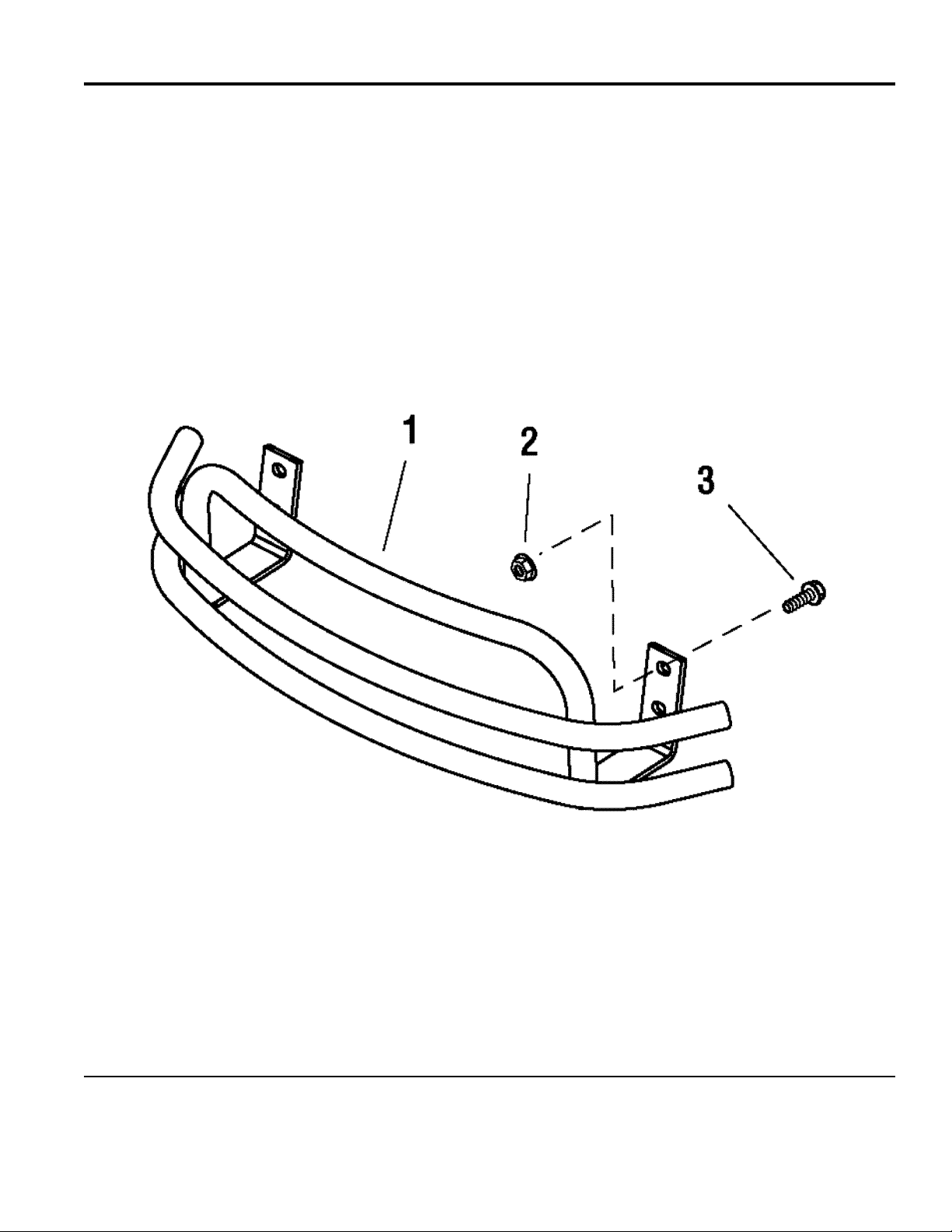
Front Bumper Group
NOTE: Unless noted otherwise,
use the standard hardware torque
specification chart.
1694923
The above parts group applies to the following Mfg. Nos.:
1694923 - Front Bumper
Briggs and Stratton Yard Power Products Group
2007Copyright © by Briggs and Stratton Corporation
Milwaukee, WI, USA. All rights reserved
4
TP 400-4570-00-AT-SMA
Page 5

Front Bumper Group
PART NO. DESCRIPTIONREF NO QTY.
Bumper Assembly 1 1731989ASM 1
Nut, Hex, Flange Lock, 5/16-18 2 1931277SM 4
Capscrew, Flange Lock, 5/16-18 x 3/4 3 1930591SM 4
Footnotes
The above parts group applies to the following Mfg. Nos.:
1694923 - Front Bumper
Briggs and Stratton Yard Power Products Group
2007Copyright © by Briggs and Stratton Corporation
Milwaukee, WI, USA. All rights reserved
5
TP 400-4570-00-AT-SMA
Page 6

Hardware Identification & Torque Specifications
Common Hardware Types
Hex Head Capscrew
Carriage Bolt
Standard Hardware Sizing
When a washer or nut is identified as 1/2”, this is the
Nominal size
second number is present it represent the
When bolt or capscrew is identified as 1/2 - 16 x 2”, this
means the
second number represents the
example, and the final number is the
bolt or screw (in this example 2 inches long).
, meaning the
Nominal size
inside diameter
, or
body diameter
threads per inch
body length
Washer
Lockwasher
Hex Nut
is 1/2 inch; if a
threads per inch
is 1/2 inch; the
(16 in this
of the
The guides and ruler furnished below are designed to
help you select the appropriate hardware and tools.
0
1/4 3/4
1/2
Nut, 1/2”
Inside
Diameter
1
1/4 3/4
1/2
Screw, 1/2 x 2
2
1/4 3/4
1/2
3
1/4 3/4
1/2
4
Body
Diameter
Body
Length
Torque Specification Chart
FOR STANDARD MACHINE HARDWARE (Tolerance ± 20%)
Hardware
Grade
Size Of
Hardware ft/lbs Nm. ft/lbs Nm. ft/lbs Nm.
8-32
8-36
10-24
10-32
1/4-20
1/4-28
5/16-18 11 15.0 17 23.1 25 34.0
5/16-24 12 16.3 19 25.8 27 34.0
3/8-16 20 27.2 30 40.8 45 61.2
3/8-24 23 31.3 35 47.6 50 68.0
7/16-14 30 40.8 50 68.0 70 95.2
7/16-20 35 47.6 55 74.8 80 108.8
1/2-13 50 68.0 75 102.0 110 149.6
1/2-20 55 74.8 90 122.4 120 163.2
9/16-12 65 88.4 110 149.6 150 204.0
9/16-18 75 102.0 120 163.2 170 231.2
5/8-11 90 122.4 150 204.0 220 299.2
5/8-18 100 136 180 244.8 240 326.4
3/4-10 160 217.6 260 353.6 386 525.0
3/4-16 180 244.8 300 408.0
7/8-9 140 190.4 400 544.0 600 816.0
7/8-14 155 210.8 440 598.4 660 897.6
1-8 220 299.2 580 788.8 900 1,244.0
1-12 240 326.4 640 870.4 1,000 1,360.0
1. These torque values are to be used for all hardware
excluding: locknuts, self-tapping screws, thread forming
screws, sheet metal screws and socket head setscrews.
2. Recommended seating torque values for locknuts:
a. for prevailing torque locknuts - use 65% of grade 5
torques.
b. for flange whizlock nuts and screws - use 135% of
grade 5 torques.
3. Unless otherwise noted on assembly drawings, all torque
values must meet this specification.
No
Marks
SAE Grade 2 SAE Grade 5 SAE Grade 8
in/lbs in/lbs
19
2.1
20
2.3
27
3.1
31
3.5
66
7.6 8 10.9 12 16.3
76
8.6 10 13.6 14 19.0
30
31
43
49
NOTES
3.4
3.5
4.9
5.5
in/lbs
41
43
60
68
420 571.2
4.6
4.9
6.8
7.7
Wrench & Fastener Size Guide
1/4
1/4” Bolt or Nut
Wrench—7/16”
5/16
5/16” Bolt or Nut
Wrench—1/2”
3/8
3/8” Bolt or Nut
Wrench—9/16”
7/16
DIA.
7/16” Bolt or Nut
Wrench (Bolt)—5/8”
Wrench (Nut)—11/16”
1/2
DIA.
1/2” Bolt or Nut
Wrench—3/4”
 Loading...