

Simplicity LTH series, Massey Ferguson 2600 series, AGCO Allis 1600 series, Broadmoor series, LTG series Service Manual
Page 1

Service & Repair Manual Broadmoor Series
Page 2

MANUFACTURING, INC.
500 N Spring Street / PO Box 997
Port Washington, WI 53074-0997 USA
© Copyright 1997 Simplicity Manufacturing, Inc.
All Rights Reserved. Printed in USA.
Page 3

1 - 1
1 General Information
Table of Contents
SECTION CONTENTS
Models Covered
Models & Identification................................................................. 1-2
Introduction
Introduction .................................................................................. 1-3
Manual Content ........................................................................... 1-3
Safety Rules
Safety Rules - General Operation................................................ 1-4
Safety Rules - Service And Maintenance .................................... 1-6
General Repair Information
Bearings & Bushings ................................................................... 1-9
Belts & Pulleys............................................................................. 1-9
Electrical Parts............................................................................. 1-9
Fasteners & Hardware............................................................... 1-10
Genuine Replacement Parts...................................................... 1-10
Hydraulic Parts .......................................................................... 1-10
Paint........................................................................................... 1-10
Required Tools & Equipment..................................................... 1-10
Systems Checks ........................................................................ 1-10
Specifications..............................................................................1-11
Torque Specifications ................................................................ 1-13
SECTION 1. GENERAL INFORMATION
Page 4
Mfg. No.
1 General Information
Models Covered In This Manual
1 - 2
MODELS COVERED &
IDENTIFICATION NUMBERS
This manual contains service information for the models
listed below. Consult the Identification Tag located on
the tractor frame for the manufacturer’s identification
number and serial number.
Always use the manufacturer’s identification number and
serial number when ordering parts or documentation.
Attachments are not covered in this manual. Refer to the
attachment operator’s manual or authorized dealer for
service information.
Transmissions are identified by identification number
tags located on the transmission casing.
1691795 12.5LTH
1691807 16LTH
1691817 1613H
1691819 1616H
1691886 12.5LTH
1691888 1613H
1691891 12.5LTG
1691893 1613G
1692071 16LTH
1692073 12.5LTH
1692075 1616H
1692076 1613H
1692182 Broadmoor
1692184 1614H
1692261 Broadmoor
1692265 1613H
1692279 Broadmoor
1692281 1614H
1692283 Broadmoor
Tractors
Description
Description
Mower Decks
1691704 38” Mower Deck
1691705 44” Mower Deck
1691815 38” Mower Deck
1691816 44” Mower Deck
Mfg. No.
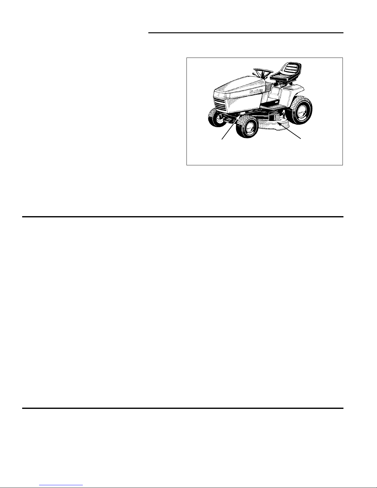
Figure 1. Tractor & Mower Identification Tags
Mower
Identification Tag
(Typical Location)
Tractor
Identification Tag
(Typical Location)
1692285 1616H
1692287 Broadmoor
1692289 1615G
1692414 Broadmoor
1692416 Broadmoor
1692416 Broadmoor
1692418 Broadmoor
1692420 Broadmoor
1692430 1614VH
1692432 1614H
1692434 1615G
1692436 1616H
1692497 2614H
1692499 2616H
1692528 Broadmoor
1692530 1615H
1692609 Broadmoor
1692613 1615H
Mfg. No.
Description
Page 5

1 - 3
1 General Information
Introduction
INTRODUCTION
This manual is divided into eight major sections of service information required for the models specified.
These sections are:
Section Title
1. General Information
2. Troubleshooting
3. Maintenance
4. Adjustments
5. Electrical
6. General Repair
7. Transmission Removal & Repair
8. Mower Deck repair
1. General Information
Contains general information such as models and manufacturing numbers, general repair instructions for components, and important safety instructions for operating and
servicing the units.
2. Troubleshooting
Provides troubleshooting information pertaining to unit
operation.
3. Maintenance
Contains basic service information for normal maintenance and off-season storage.
4. Adjustments
Contains basic service information and procedures for
adjustments.
5. Electrical
Contains information and service procedures for troubleshooting and repairs of electrical systems.
6. General Repair
Covers disassembly, inspection, and repair of all major
assembly groups except transmissions.
7. Transmission Removal & Repair
Covers removal, disassembly, inspection, and repair of
Simplicity serviceable transmissions.
8. Deck Repair
Covers common mower deck service procedures.
Since part numbers are subject to change and may vary
by model year and manufacturing number, all parts in
this manual are referred to by general description.
Specific part number information may be found in the
respective Parts Manual for the unit being serviced.
Always use the manufacturing number that appears on
the Identification Tag of the unit you are servicing to
identify component part numbers.
MANUAL CONTENT
This manual is intended primarily for use by dealer service personnel as a technical reference manual or as a
compliment to normal service training.
While the information in this manual has been developed
to permit mechanics and service technicians to perform
most service procedures quickly and effectively, it is
assumed that those using this manual will have some
outdoor power equipment service experience or other
basic power equipment service training with similar types
of products.
In addition, it is assumed that all those performing service on these units are familiar with the general principles of operation of these units, and understand all operating controls, safety instructions, and normal handling
precautions for servicing large, high horsepower riding
tractors and mowers.
Engine information is available from the appropriate
engine manufacturer in a separate service manual.
General engine information and basic engine troubleshooting information is provided, but is intended for
general guidance only. The engine manufacturer’s manual should be always be consulted first before making
any major adjustments, part changes, or other major
repairs.
This manual includes all relevant service information for
model years 1990 through 1995, and whenever necessary, includes inset illustrations or other references to
help identify previous part designs and alternative service procedures.
The service techniques in this manual also assume that
the person providing service has access to a standard
assortment of mechanic’s hand tools, and approaches
most disassembly and repair procedures with availability
of these basic tools in mind. Whenever specialized or
custom tools are available to save time, reduce effort, or
improve overall service efficiency, the most effective safe
repair method available should be utilized.
Page 6

1 General Information
Safety Rules
1 - 4
Read these safety rules and follow them closely. Failure to obey these rules could result in loss of control of
rider, severe personal injury or death to you, or bystanders, or damage to property or equipment. This
mowing deck is capable of amputating hands and feet and throwing objects. The triangle in text
signifies important cautions or warnings which must be followed.
GENERAL OPERATION
• Read, understand, and follow all instructions in the
manual and on the unit before starting.
• Only allow responsible adults, who are familiar with
the instructions, to operate the unit.
• Clear the area of objects such as rocks, toys, wire,
etc., which could be picked up and thrown by the
blade(s).
• Be sure the area is clear of other people before mowing. Stop unit if anyone enters the area.
• Never carry passengers.
• Do not mow in reverse unless absolutely necessary.
Always look down and behind before and while travelling in reverse.
• Be aware of the mower discharge direction and do
not point it at anyone. Do not operate the mower
without either the entire grass catcher or the deflector
in place.
• Slow down before turning.
• Never leave a running unit unattended. Always
disengage the PTO, set parking brake, stop engine,
and remove keys before dismounting.
• Turn off the PTO switch to disengage the blades
when not mowing.
• Stop engine before removing grass catcher or
unclogging chute.
• Mow only in daylight or good artificial light.
• Do not operate the unit while under the influence of
alcohol or drugs.
• Watch for traffic when operating near or crossing
roadways.
• Use extra care when loading or unloading the unit
into a trailer or truck.
SLOPE OPERATION
Slopes are a major factor related to loss-of-control and
tip-over accidents, which can result in severe injury or
death. All slopes require extra caution. If you cannot
back up the slope or if you feel uneasy on it, do not mow it.
Do
• Follow manufacturer’s recommendations of wheel
weights or counterweights to improve stability.
• Mow up and down slopes, not across.
• Remove obstacles such as rocks, tree limbs, etc.
• Watch for holes, ruts, or bumps. Uneven terrain could
overturn the unit. Tall grass can hide obstacles.
• Use slow speed. Choose a low gear so that you will
not have to stop or shift while on the slope.
• Use extra care with grass catchers or other attachments. These can change the stability of the unit.
• Keep all movement on the slopes slow and gradual.
Do not make sudden changes in speed or direction.
Do Not
• Do not start or stop on a slope. If tires lose traction,
disengage the blade(s) and proceed slowly straight
down the slope.
• Do not turn on slopes unless necessary, and then,
turn slowly and gradually downhill, if possible.
• Do not mow near drop-offs, ditches, or embank-
ments. The mower could suddenly turn over if a
wheel is over the edge of a cliff or ditch, or if an edge
caves in.
• Do not mow on wet grass. Reduced traction could
cause sliding.
• Do not try to stabilize the unit by putting your foot on
the ground.
• Do not use grass catcher on steep slopes.
WARNING - SLOPE OPERATION
Never operate on slopes greater than 30 percent (16.7°)
which is a rise of three feet vertically in 10 feet horizontally. When operating on slopes that are greater than 15
percent (8.5°) but less than 30 percent use front counterweights and rear wheel weights (see your dealer). Select
slow ground speed before driving onto slope. In addition
to front and rear weights, use extra caution when operating on slopes with rear-mounted grass catcher. Mow UP
and DOWN the slope, never across the face, use caution
when changing directions and DO NOT START OR STOP
ON SLOPE.
Page 7

1 - 5
1 General Information
Safety Rules
CHILDREN
Tragic accidents can occur if the operator is not alert to
the presence of children. Children are often attracted to
the unit and the mowing activity. Never assume that children will remain where you last saw them.
• Keep children out of the mowing area and under the
watchful care of another responsible adult.
• Be alert and turn unit off if children enter the area.
• Before and when backing, look behind and down for
small children.
• Never carry children. They may fall off and be seriously injured or interfere with safe unit operation.
• Never allow children to operate the unit.
• Use extra care when approaching blind corners, shrubs,
trees, or other objects that may obscure vision.
TRANSPORTING AND STORAGE
• Always observe safe refueling and fuel handling practices when refueling the tractor after transportation,
service, or storage.
• Always follow the engine manual instructions for
storage preparations when preparing the tractor for
both short and long term periods.
• Always follow the engine manual instructions for
proper start-up procedures when returning the unit to
service.
• Never store the unit or fuel container inside where
there is an open flame or pilot light, such as in a
water heater, gas furnace, or stove. Allow unit to cool
before storing.
GENERAL SAFETY
All WARNING, CAUTION, and instructional messages
appearing in decals on the tractor and mower being serviced must be carefully read and obeyed. Severe personal injury can result when these instructions are not
followed. The information is for your safety, as well as
those who operate the equipment, and it is important!
If any of these decals are lost or damaged, replace them
at once. See your Parts Manual for replacement information.
These labels are easily applied and will act as a constant
visual reminder to you, the operator, and others who may
use the equipment, to follow the safety instructions necessary for safe, effective operation.
Page 8

1 General Information
Safety Rules
1 - 6
SERVICE AND MAINTENANCE
The service information provided in this manual is intended to provide you with the knowledge required to perform
a wide range of service procedures on the listed equipment.
While appropriate safety reminders and safety warnings
have been included here and elsewhere in this manual to
help promote the use of safe service techniques, you
must also observe all appropriate shop safety rules
whenever performing these procedures.
No single manual, including this one, can include every
possible warning or safety instruction necessary to guarantee complete safety - you must apply your common
sense and knowledge of shop and power equipment
safety whenever performing service, whenever working
around others who are operating, servicing, or handling
equipment, and whenever you are present in a work
environment where hand or power tools, shop equipment, or outdoor power equipment may be present.
This includes taking the necessary safety precautions to
help ensure a safe workplace, exercising reasonable
care to avoid unsafe acts, and being alert for potential
hazards as you move about the workplace or engage in
various service activities.
If you encounter a service situation involving the use of
an unfamiliar tool, procedure, or part, and rereading the
appropriate section of this manual does not provide the
information you want, contact your Simplicity dealer
before proceeding. Never attempt a repair that you’re
not sure about, since help is usually never more than just
a phone call away.
Practicing safe service procedures not only helps protect
you and those you work around, it also contributes to
providing safe, reliable equipment .
Personal Protective Equipment
• Wear protective safety glasses whenever using hand
or power tools, shop equipment, and whenever working under power equipment to protect your eyes from
falling debris and small parts.
• Wear safety goggles or full face protection when handling battery electrolyte fluid, or when performing
grinding or sharpening operations that produce
sparks or flying debris. Extensive grinding may
require the use of protective sleeves and an apron.
• Wear work gloves when handling sharp surfaces
such as mower blades, or when working around
sharp edges. Never wear gloves that are loose fitting
or that have tie straps, as these could cause your
hands to get caught by rotating parts, resulting in
serious injury. Chemical-resistant Rubber gloves are
recommended when handling or pouring battery electrolyte.
• Steel-toe safety shoes are highly recommended to
protect feet from falling tools, heavy parts, and other
shop equipment.
Fuel Handling Safety
• Always use extra care when handling gasoline gasoline is highly flammable, and gasoline vapors
are explosive as well as toxic if inhaled.
• Never store fuel indoors, or refuel a unit indoors.
Gasoline vapors can easily travel unseen to distant
sources of ignition such as pilot lights or open flames
on water heaters, furnaces, stoves, or other gas
operated appliances, sparks from electric motors or
other electrically-operated tools and equipment, welding equipment, grinders, or burning smoking materials. Contact with these or any other sources of ignition will cause an explosion and/or fire, serious personal injury, and damage to property and equipment.
• Never transfer gasoline from one container to another
unless the containers are connected by an approved
grounding strap. Hand or power operated transfer
pumps can generate a static charge of electricity,
causing dangerous sparking and ignition of fuel or
fuel vapors. Always follow the pump manufacturer’s
safety and operating instructions.
• Use only approved containers for fuel, and always
handle the container with extreme care to avoid
spillage or leaking of explosive vapors.
• Never smoke or allow others in the area to smoke
while refilling the fuel tank, or when handling gasoline cans. Make sure any smoking materials that had
been in use in the area are fully extinguished before
opening a fuel can or starting refueling .
Page 9

1 - 7
1 General Information
Safety Rules
Exhaust Gas Safety
• Internal combustion engines produce and exhaust
Carbon Monoxide (CO), an odorless, colorless, gas
that causes dizziness, nausea, flu-like symptoms,
unconsciousness, or even brain damage or death, if
breathed for prolonged periods.
• If exposed to Carbon Monoxide gas, get to a fresh air
source immediately and seek medical attention. CO
can build up in your blood, and can cause lingering
symptoms or permanent damage if left untreated.
• Operate the unit outdoors or in a well ventilated area,
or pipe exhaust gases out of the work area to an outside location where the exhaust can be dissipated
safely away from doors, windows, air conditioners, or
other potential sources of outside-air intake that could
permit reentry of hazardous fumes.
• Never enter an enclosed area where an engine has
been running and exhaust gases have been allowed
to collect. Open adjacent windows or doors first to
permit outside air to ventilate the area, and allow sufficient time for a complete air exchange to occur.
Battery/Electrolyte Safety
• Lead-Acid batteries use an electrolyte containing sulphuric acid, a highly corrosive liquid that can cause
severe chemical burns if allowed to come into contact
with skin, or blindness if allowed to contact your eyes.
Always wear approved eye goggles or a full face
shield and protective gloves when handling electrolyte or filling the battery.
• Lead-acid batteries also produce hydrogen, a colorless, highly explosive gas that can be easily ignited
by a single spark. Charging the battery incorrectly or
hooking up jumper cables improperly can cause
sparking, and must be avoided. Always follow recommended battery charging and jumper cable procedures.
• When removing or installing battery cables, disconnect the negative cable FIRST, and reconnect it
LAST. If not done in this order, the positive terminal
could be accidentally shorted to the frame by a tool,
creating a dangerous spark that can ignite nearby
fuel vapors or escaping hydrogen gas from the battery.
• Keep battery securely fastened in position with vent
tube directed down and out of battery compartment.
Replace battery if electrolyte leakage occurs. Make
sure the battery vent tube is properly installed, and is
not plugged with clippings or other debris. Replace
the vent tube if cracked, damaged, or missing from
unit.
• Old batteries should be disposed of by recycling.
Electrical System Safety
• Loose connectors, worn wires, damaged wire insulation, and loose termination hardware can cause
sparks, short-circuits, and erratic equipment operation. Always check wiring for damage, and make
appropriate repairs before placing unit back into operation.
• Use care when working around exposed terminals to
prevent short-circuiting the electrical system.
Sparking, electric shocks, and damage to the system
may result from accidental contact between terminals
and metal hand tools.
Elevation Of Unit Safety
• Always support unit on approved jack stands when
working on an elevated unit, and keep unit from
rolling by engaging parking brake and placing wheel
chocks behind wheels still on floor or work table.
• Secure unit to work-surface of scissor-lift worktables
or other powered lift tables in accordance with the
manufacturer’s instructions. Unsecured units may
roll unexpectedly while work is being done, causing
injuries.
• Never work under an elevated unit unless it is properly supported by jack stands, locked from rolling with
wheel chocks or equivalent, and you can quickly
escape from under the unit in an emergency using a
rolling device such as a mechanic’s creeper.
• Always protect your eyes from falling debris or small
parts by wearing approved safety glasses or goggles.
• Remove the ignition key and disconnect the spark
plug wires before working under a unit. Accidental or
inadvertent starting could result in serious injuries.
Proper Tool Use
• Use power and hand tools only for the use that they
were designed. Never alter or modify tools, or improvise using tools that are not suitable for the job at
hand.
• Keep all hand and power tools in good repair, and put
them away when done to avoid cluttering the work
area. Use extra care when using corded tools
around moving or rotating parts such as belts and
pulleys, since the cord could get caught and suddenly
pull the tool, or you, into the area of moving parts.
• Always check the unit to ensure that all hand and
power tools and tool attachments have been
removed from the unit after use. Small tools and tool
attachments left on the equipment can fall into the
cutting path when the unit is placed into service, and
become a hazard to bystanders if struck by mower
blades.
Page 10

1 General Information
Safety Rules
1 - 8
Work Area Safety
• Always keep the work area clear of clutter from discarded parts, and debris from parts boxes or packaging materials. Small parts, hardware items, and other
debris or refuse left lying around can become slip,
trip, and fall hazards if not removed and discarded of
properly.
• Always observe general shop safety rules for housekeeping, and tend to oil spills and other spilled fluids
promptly to prevent slip and fall injuries.
• Allow sufficient work area around the equipment you
are working on to permit comfortable working positions. Never put yourself in a position that would prevent you from escaping quickly in the event of emergencies such as sudden shifts in equipment position,
fire, or other situations requiring an immediate reaction on your part.
Compressed Air Safety
• Always use care when using compressed air to blow
dirt and debris off equipment - always direct the air
blast away from yourself and others in the area, and
protect your eyes with safety glasses to prevent injury
from particles that may blow back toward your face.
• Never use high pressure air directly against your skin
to clean dirt and debris - the air pressure could actually force foreign material or fluids into your skin,
causing serious injuries.
• Use care when filling tires - lawn and garden tractors
utilize low pressure tires, and over-pressurization is
hazardous to you and anyone who operates the
equipment with improper tire pressures. Always consult the air pressure recommendations for the unit
involved before adding additional air to the tires.
Grease & Lubricant Safety
• Normal service and maintenance involves the use of
oils and greases that could present a fire hazard if
not handled properly. Always dispose of oily rags
properly to prevent fires caused by spontaneous
combustion.
• Spilled lubricants pose dangerous slip hazards and
must be taken care of immediately. Wipe up spills
carefully, or use absorbent materials to soak up
spilled fluids. Always dispose of rags, paper towels,
and other saturated absorbents properly.
• Store oils and greases away from flame or other ignition sources. Petroleum-based fluids can be ignited
by smoking materials and sparks - always treat oils
and greases as potentially flammable materials.
Always cap oil and grease containers when done
using, and store or dispose of properly.
General Servicing Safety
• Always check safety devices and switches for proper
operation - never alter these devices or make temporary or makeshift repairs. Use only factory-authorized parts and procedures, and check newlyinstalled parts for proper operation.
• Make sure all hardware items are properly tightened,
especially blade attachment bolts. Replace any hardware that appears damaged.
• Check brake operation, and adjust or repair as
required. Always comply with factory specifications
on settings and adjustments.
• Check grass catcher components for wear, damage,
or deterioration, and replace with factory authorized
parts if necessary.
• Always make repairs using factory authorized
replacement parts only. Using parts that don’t meet
factory specifications can result in sudden or premature failures, poor or erratic equipment performance,
and potential safety hazards to operators and
bystanders.
• Always comply with factory specifications on settings
and adjustments when installing new parts, making
repairs, or performing routine service procedures.
• Always test repairs before releasing units to customers, paying special attention to any items that are
safety-related. Correct any problems noted, and recheck to ensure that the problems have been fully
remedied.
• Make sure all safety and operating instruction decals
are legible, properly located, and securely attached.
Replace any decals that can’t be read or are in danger of falling off.
• Always advise equipment owners of any potential
operating or safety problems that may be arising due
to anticipated wear, and request that the owner
address the problem before a hazard develops.
• Never allow a unit to be placed back into service if a
serious safety or operating problem is evident.
Advise the owner of the problem and the possible
hazards associated with the problem, and request
permission to correct the deficiencies.
• Use extreme care when working on older models that
do not have all of the latest safety devices and
switches. Disengage the PTO and transmission
before starting the unit, or commencing repairs.
• Always use care when removing or installing parts to
prevent damage from dropping or rough handling.
Support heavy parts properly to prevent damage or
personal injury to yourself and others.
Page 11

1 - 9
1 General Information
Repair Information
GENERAL REPAIR INFORMATION
In addition to providing specific repair procedures for the
equipment listed at the beginning of this section, this
manual provides the following additional general instructions for dealing with repairs to various types of components.
This information is designed to help you deal more effectively with these components by providing basic service
knowledge and other useful tips.
Bearings & Bushings
Roller bearings, ball bearings, and bushings are used to
provide support to rotating shafts and other parts such as
gears, pulleys, and sprockets that are used to transmit
rotary motion. Over time, bearings and bushings may
require additional lubrication to transmit this rotary
motion with minimal friction, or may need replacement
due to normal operation and wear. Normal service for
bearings and bushings includes removal, cleaning,
inspection, lubrication, and replacement.
REMOVAL
Most bearings and bushings used on the listed equipment can be easily removed by following the appropriate
detailed procedures found throughout this manual. Care
should always be exercised to avoid scratching or damaging the bearing or bushing, the mounting shaft, and
surrounding components. Bearing or bushing removal is
usually necessary when excessive play or wobble is
noticed on the part it supports, when unusual noise or
vibration is apparent, or when a burning smell is present
at the bearing location.
CLEANING
Sealed bearings and bushings can be cleaned by careful
wiping with a cloth. Bearings with one-sided or removable shields and plain bushings can be cleaned by
immersion in safety solvent, and brushing with a part
cleaning brush. Oil-impregnated bushings, and bushings
made of nylon or other synthetic materials, can be
cleaned with safety solvents, or wiped clean, but should
not be immersed in solvent for periods longer than that
necessary to remove heavy or caked-on build-ups of
grease. All petroleum-based solvents are flammable, so
appropriate precautions regarding flames, sparks, and
other ignition sources should always be observed.
Gasoline should never be used because of its volatility
and its highly toxic nature.
INSPECTION
Once cleaned, bearings can be properly inspected for
wear, scratches, visible damage such as corrosion,
cracked seals or scorching, and rough, or noisy, operation. Bushings can be visually checked for scratches,
uneven wear, or other visual damage.
LUBRICATION
After passing inspection, bearings and bushings should
be lubricated in accordance with factory specifications,
and reinstalled according to the appropriate installation
instructions. New bearings and bushings must also be
properly lubricated before use. For optimal performance,
and as a practical preventive maintenance measure,
bearings and bushings used in pairs or multiple sets
should all be replaced at the same time.
Belts & Pulleys
Belts and pulleys transmit rotary motion from power
sources to work components, providing the force needed
to drive transmissions, operate mower decks, and power
various attachments. This continual use eventually
causes belts to wear out, and over time may also require
the replacement of pulleys and pulley bearings.
Belt wear and various types of damage are easily
checked by visual examination, which is covered in
greater detail elsewhere in this manual. Pulleys may
also be checked visually for wear or apparent damage,
but pulley bearings usually require removal, cleaning,
and inspection to determine if replacement is required.
Belt and pulley life can be optimized by making sure that
proper belt tension and alignment are observed when
belts are installed. Proper belt tension and alignment
should also be maintained by performing periodic checks
and adjustments. In addition, only factory authorized
replacement belts will minimize problems caused by
size, thermal instability, and variations in quality.
Electrical Parts
The electrical parts used on these units has been specifically engineered for outdoor power equipment, and is
designed to provide years of reliable operation. As with
all electrical components and systems, electrical contacts must be kept clean and dry, and all terminations
must be securely fastened or connected. Also, all electrical components, wiring, and connectors should be periodically inspected for corrosion, signs of excessive heat
build-up, or other damage that signals that it is time to
repair or replace the item.
Specific procedures for electrical troubleshooting and
most common repairs is covered in separate sections of
this manual.
Page 12

1 General Information
Repair Information
1 - 10
Fasteners & Hardware
All hardware and fasteners used in this equipment must
meet factory specifications for SAE grade, size, and
torque, and must be kept securely tightened. Locking
hardware that degrades with use should be replaced
when service is performed in affected areas. Always
observe factory specifications for torque, or consult the
torque chart for torque information.
Genuine Replacement Parts
Only factory authorized replacement parts should be
used when making repairs or performing routine maintenance. The use of parts that do not meet stringent factory specifications can cause poor performance, premature
failures, and lead to potential safety hazards. In addition,
the use of non-factory authorized replacement parts will
void your warranty.
Hydraulic Parts
Hydraulic parts are adversely affected by dirt and contamination, and care must be exercised when performing
service on these parts to prevent foreign material from
entering. Specific service information appears elsewhere in this manual, and all precautions and procedures must be followed when repairing or servicing these
parts.
Paint
The paint on outdoor power equipment provides for an
attractive appearance, as well as a barrier to corrosion
caused by exposure to moisture in the environment.
Scratches, abrasions, and other damage to painted surfaces should be repaired promptly to prevent the formation of rust and premature part failure. Factory supplied
paints are available that provide both an accurate color
match and superior corrosion resistance.
Required Tools & Equipment
All repairs in this manual can be accomplished with standard mechanic’s hand tools. The use of appropriate
power tools such as impact wrenches and power drivers
may aid in part removal and replacement, but care must
be exercised to avoid causing damage to components
from excessive tightening. Transmission service, steering service, tire and wheel service, and service to components located under the frame also requires the use of
a jack with suitable capacity, and jack stands to support
the unit being worked on.
Systems Checks
In addition to performing individual component service,
components affected by related parts changes should
also receive attention at the time service is performed.
Examples of this include part replacements that are part
of a safety device, electrical components, transmission
components, and pulleys that are part of the same power
delivery system. Giving attention to related parts will
help ensure that the parts most likely to be affected by
the wear of similar or nearby parts, or parts subjected to
the same amount of stress or wear, are given appropriate attention before a failure can occur.
Page 13

1 - 11
1 General Information
Specifications
Capacity: 4 Gallons (15.1 L)
Muffler Quiet Compact, Low Back Pressure
15 HP Briggs & Stratton
Make Briggs & Stratton
Model Vanguard
Horsepower 15 HP @ 3600 rpm
Cylinders 1
Bore 3.44 In. (87.3 mm)
Stroke 3.06 In. (77.7 mm)
Displacement 29.3 Cu. In. (480 cc)
Construction Overhead Valve, Cast Iron Sleeves,
Aluminum Crankcase
Electrical 12 Volt, 9 Amp Alternator Regulated
System Battery: 340 Cold Cranking Amps, 41 min.
Reserve Capacity, Industrial Rated
Starter Motor
Ignition Magnetron Electronic Ignition
Air Cleaner Ducted Paper Cartridge and Foam
Precleaner large 325 sq. in. Air Filtering
System
Lubrication Splash Lube with Circulating Pump & Filter
Oil Capacity 3.5 Pints w/Filter (1.6 L)
Fuel Tank Material: Non-Corrosive Polyethylene
Fuel Tank Gauge Built Into Filler Cap
Capacity: 4 Gallons (15.1 L)
Muffler Quiet Compact, Low Back Pressure
TRANSMISSION
Gear Models
Type Spur Gear
Material Gear: Heat Treated
Shaft: Hardened and Ground
Bearings: Needle Roller, Sealed Ball
and Bushings
Lubrication Bentonite Grease
Speeds Five Forward, One Reverse
@ 3400 rpm 1st: 1.1 MPH (1.8 km/h)
2nd: 2.2 MPH (3.5 km/h)
3rd: 3.4 MPH (5.5 km/h)
4th: 4.2 MPH (6.8 km/h)
5th: 5.1 MPH (8.2 km/h)
Reverse: 2.4 MPH (3.9 km/h)
Differential Spur Gear Type
Hydro Models
Type Hydrostatic
Pump Variable Displacement Piston
Specifications
ENGINE
14 & 16 HP Briggs & Stratton
Make Briggs & Stratton
Model Vanguard V-Twin
Horsepower 14 & 16 HP @ 3600 rpm
Cylinders 2
Bore 2.68 In. (68 mm)
Stroke 2.60 In. (66 mm)
Displacement 29.3 Cu. In. (480 cc)
Construction Overhead Valve, Cast Iron Sleeves,
Aluminum Crankcase
Electrical 12 Volt, 16 Amp Alternator Regulated
System Battery: 340 Cold Cranking Amps, 41 min.
Reserve Capacity, Industrial Rated
Starter Motor
Ignition Magnetron Electronic Ignition
Air Cleaner Ducted Paper Cartridge and Foam
Precleaner large 325 sq. in. Air Filtering
System
Lubrication Full Pressure Lube w/Oil Filter
Oil Capacity 3.5 Pints w/Filter (1.6 L)
Fuel Tank Material: Non-Corrosive Polyethylene
Fuel Tank Gauge Built Into Filler Cap
Capacity: 4 Gallons (15.1 L)
Muffler Quiet Compact, Low Back Pressure
14 HP Kohler
Make Kohler
Model Command™
Horsepower 14 HP @ 3600 rpm
Cylinders 1
Bore 3.43 In. (87 mm)
Stroke 2.64 In. (67 mm)
Displacement 24.3 Cu. In. (398 cc)
Construction Overhead Valve, Cast Iron Sleeves,
Aluminum Crankcase
Electrical 12 Volt, 15 Amp Alternator Regulated
System Battery: 340 Cold Cranking Amps, 41 min.
Reserve Capacity
Ignition High Energy Electronic Ignition
Air Cleaner Ducted Paper Cartridge and Foam
Precleaner
Lubrication Full Pressure Lube w/Oil Filter
Oil Capacity 4.0 Pints w/Filter (1.9 L)
Fuel Tank Material: Non-Corrosive Polyethylene
Fuel Tank Gauge Built Into Filler Cap
Page 14

1 General Information
Specifications
1 - 12
Motor Fixed Displacement Piston
Hydraulic Fluid 3.5 Quarts (3.3 L) SAE 20W-50 Premium
Control Single Lever Release
Lever for Manual Tractor Movement,
Continuously Variable, Forward &
Reverse, without Braking
Speeds Forward: 0-5.5 MPH (0-8 km/h)
@ 3400 RPM Reverse: 0-1.7 MPH (0-2.7 km/h)
Differential Automotive Type
CONTROLS
Steering Full Circle Steering Wheel System Gear
and Sector
Clutch/Brake Location Right Front
Pedal Combination Clutch/Brake/Parking Brake
Pedal Standard Equipment
Location -Mower Lift Lever Right Side, Lower Dash
Tower
-PTO Clutch Electric, Dash Mounted
-Ground Speed Lever Dash Mounted
-Ignition Key Switch on dash panel
-Throttle Lever and Choke Lever on dash
panel
-Light Switch on dash panel
-Separate Indicator Lights for Safety
-Interlock Switch Operator Present
-Transmission Neutral, PTO Disengaged
-Clutch/Brake Pedal Depressed
-Low Oil Pressure Warning Light
CHASSIS
Frame Heavy Gauge Steel Channel
Power Take-Off Point Front
Engine Mounting Above Front Axle
Pivot Point Location Front Axle
Rear Wheels Tire Size 20 x 8.00-10 Turf Type
Pneumatic Inflation Pressure 6-8 psi
(41-55 kPa)
Front Wheels Tire Size 15 x 6.00-6
Pneumatic Inflation Pressure 12-15 psi
(82-103 kPa)
Front Axle 1-3/4” x 3” 12 Ga. Fabricated Rectangular
Tube
Accessibility Hood Tips Forward
Seat Type Bucket, High Back, Adjustable w/
Spring Suspension; Adjustable to Suit
Different Size Operators
Turning Radius Inside Rear Tire 16 In. (40.6 cm)
DIMENSIONS
Tractor
Overall Length 67 In. (170.2 cm)
Overall Width 35 In. (88.9 cm)
Height To Top of Steering Wheel 40 In. (101.6 cm)
To Top of Engine Cover 34 In. (86.7 cm)
Wheel Base 48 In. (121.9 cm)
Weight Net: 455 lbs. (206 kg)
(approx.) w/o Shipping: 575 lbs. (261 kg)
mower
Mower - 38"
Effective
Cutting Width 38 In. (96.5 cm)
Overall Width
with Deflector 49.5 In. (125.7 cm)
Weight 100 lbs. (45 kg)
Variable
Cutting Ht. 1-3.6 in. (2.5 to 91 cm)
Blade
Arrangement Two Blades
Mower Drive V-Belt From Tractor PTO Pulley
Spindle
Bearings Lubricated and Sealed Ball Bearings
Mower - 44"
Effective
Cutting Width 44 In. (111.8 cm)
Overall Width
with Deflector 56 In. (142.2 cm)
Weight 115 lbs. (52 kg)
Variable
Cutting Ht. 1-3.6 In. (2.5 to 91 cm)
Blade
Arrangement Three Staggered Blades
Mower Drive V-Belt From Tractor PTO Pulley
Spindle
Bearings Lubricated and Sealed Ball Bearings
Page 15

1 General Information
Torque Specifications
1 - 13
SIZE SAE GRADE #2 SAE GRADE #5 SAE GRADE #8
in/lbs in/lbs
in/lbs
ft/lbs Nm. ft/lbs Nm. ft/lbs Nm.
8-32 19 2.1 30 3.4 41 4.6
8-36 20 2.3 31 3.5 43 4.9
10-24 27 3.1 43 4.9 60 6.8
10-32 31 3.5 49 5.5 68
7.7
1/4-20 66 7.6 8 10.9 12 16.3
1/4-28 76
8.6 10 13.6 14 19.0
5/16-18 11 15.0 17 23.1 25 34.0
5/16-24 12 16.3 19 25.8 27 34.0
3/8-16 20 27.2 30 40.8 45 61.2
3/8-24 23 31.3 35 47.6 50 68.0
7/16-14 30 40.8 50 68.0 70 95.2
7/16-20 35 47.6 55 74.8 80 108.8
1/2-13 50 68.0 75 102.0 110 149.6
1/2-20 55 74.8 90 122.4 120 163.2
9/16-12 65 88.4 110 149.6 150 204.0
9/16-18 75 102.0 120 163.2 170 231.2
5/8-11 90 122.4 150 204.0 220 299.2
5/8-18 100 136 180 244.8 240 326.4
3/4-10 160 217.6 260 353.6 386 525
3/4-16 180 244.8 300 408.0 420 571.2
7/8-9 140 190.4 400 544.0 600 816.0
7/8-14 155 210.8 440 598.4 660 897.6
1-8 220 299.2 580 788.8 900 1,244.0
1-12 240 326.4 640 870.4 1,000 1,360.0
NOTES
1. These torque values are to be used for all hardware excluding: locknuts,
self-tapping screws, thread forming screws, sheet metal screws and socket
head setscrews.
2. Recommended seating torque values for locknuts:
a. for prevailing torque locknuts - use 65% of grade 5 torques.
b. for flange whizlock nuts and screws - use 135% of grade 5 torques.
3. Unless otherwise noted on assembly drawings, all torque values must meet
this specification.
TORQUE SPECIFICATIONS FOR
STANDARD MACHINE HARDWARE
(Tolerance ± 20%)
Page 16

1 General Information
Notes
1 - 14
Page 17

2 - 1
2 Troubleshooting
Table of Contents
SECTION CONTENTS
Troubleshooting
Troubleshooting the Tractor ......................................................... 2-2
Troubleshooting the Mower.......................................................... 2-3
SECTION 2. TROUBLESHOOTING
Page 18

2 Troubleshooting
Tractor Troubleshooting
2- 2
TROUBLESHOOTING
The troubleshooting guide below lists some common
problems, their causes, and remedies.
See the repair information on the following sections for
instructions on how to perform most of these minor
repairs yourself. If you prefer, all of these procedures
can be performed for you by your local authorized dealer.
WARNING
Never attempt to perform repairs while the engine
is running.
Always turn the engine off and remove the key.
FAILURE TO COMPLY WITH THIS, AND OTHER,
SAFETY REQUIREMENTS CAN RESULT IN SERIOUS PERSONAL INJURY.
TROUBLESHOOTING THE TRACTOR
Engine will not turnover or start. 1. Ground speed control lever Shift into neutral.
not in neutral-start position.
2. PTO (electric clutch) switch Place in OFF position.
in ON position.
3. Out of fuel. If engine is hot, allow it to cool, then refill
the fuel tank.
4. Engine flooded. Push choke knob in (twin cylinder models)
or move throttle control out of CHOKE
position (single cylinder models).
5. Circuit breaker tripped. Wait one minute for automatic reset.
Replace if defective.
6. Battery terminals require See Electrical Troubleshooting Section.
cleaning.
7. Battery discharged or dead. Recharge or replace.
8. Wiring loose or broken. Visually check wiring & replace broken or
frayed wires. Tighten loose connections.
9. Solenoid or starter motor faulty. Repair or replace. See Electrical
Troubleshooting Section.
10. Safety interlock switch or Replace as needed. See Electrical
module faulty. Troubleshooting Section.
11. Spark plug(s) faulty, fouled Clean and gap or replace.
or incorrectly gapped. See engine manual.
12. Water in fuel. Drain fuel & refill with fresh fuel.
13. Gas is old or stale. Drain fuel & replace with fresh fuel.
14. Foot pedal not depressed. Depress pedal.
Engine starts hard or runs poorly. 1. Fuel mixture too rich. Clean air filter. Check choke adjustment
(engine speed control).
2. Carburetor adjusted incorrectly. See engine manual.
3. Spark plug(s) faulty, fouled, or Clean and gap or replace.
incorrectly gapped. See engine manual.
Engine knocks. 1. Low oil level. Check/add oil as required.
2. Using wrong grade oil. See engine manual.
Excessive oil consumption. 1. Engine running too hot. Clean engine fins, blower screen and
air cleaner.
2. Using wrong weight oil. See engine manual.
3. Too much oil in crankcase. Drain excessive oil.
Engine exhaust is black. 1. Dirty air filter. Replace air filter. See engine manual.
2. Engine speed control Change engine speed.
is in choke position.
Engine runs, but tractor will 1. Ground speed control lever Shift in forward or reverse.
not drive. in neutral.
2. Transmission release lever Move into drive position.
in “push” position.
(Hydro models only)
3. Belt is broken. See Drive Belt Replacement.
4. Drive belt slips. See problem and cause below.
5. Brake is not fully released. See Brake Adjustment.
Page 19

2 - 3
2 Troubleshooting
Mower Troubleshooting
Tractor Troubleshooting Cont.
Tractor drive belt slips. 1. Clutch is out of adjustment. See Adjustments Section.
2. Pulleys or belt greasy or oily. Clean as required.
3. Belt stretched or worn. Replace with correct belt.
4. Idler pulley pivot bracket Remove idler pulley, clean and lubricate.
“frozen” in declutched position.
Brake will not hold. 1. Brake is incorrectly adjusted. See Brake Adjustment.
2. Internal brake disc on See Brake Adjustment and
transaxle worn. Transmission Repair Sections.
Tractor steers hard or 1. Steering linkage is loose. Check and tighten any loose connections.
handles poorly. See Steering Gear Adjustment.
2. Improper tire inflation. Check and correct.
3. Spindle bearings dry. Grease spindles. See Lubricating the
Tractor.
Drive belt does not stop when 1. Belt stops or belt tension See Adjustments Section.
clutch/brake pedal depressed. out of adjustment.
TROUBLESHOOTING THE MOWER
Mower will not raise. 1. Lift link not properly attached Attach or repair.
or damaged.
Mower cut is uneven. 1. Mower not leveled properly. See Mower Adjustment.
2. Tractor tires not inflated See Maintenance Section.
equally or properly.
Mower cut is rough looking. 1. Engine speed too slow. Set to full speed.
2. Ground speed too fast. Slow down.
3. Blades are dull. Sharpen or replace blades.
See Mower Blade Service.
4. Mower drive belt slipping Clean or replace belt as necessary.
because it is oily or worn.
5. Check PTO (Electric Clutch) See Adjustments Section.
Adjustment.
6. Blades not properly fastened See Servicing the Mower Blades.
to arbors.
Engine stalls easily with 1. Engine speed too slow. Set to full throttle.
mower engaged. 2. Ground speed too fast. Slow down.
3. Carburetor improperly adjusted. See Engine Manual.
4. Cutting height set too low. Cut tall grass at maximum cutting
height during first pass.
5. Discharge chute jamming Cut grass with discharge pointing toward
with cut grass. previously cut area.
Excessive mower vibration. 1. Blade mounting screws Tighten to 50-70 ft.lbs. (74 N.m.).
are loose.
2. Mower blades, arbors, Check and replace as necessary.
or pulleys are bent.
3. Mower blades are out Remove, sharpen, and balance blades.
of balance. See Servicing the Mower Blades.
4. Belt installed incorrectly. Reinstall Correctly.
Excessive belt wear or breakage. 1. Belt tension too tight. Adjust belt tension.
2. Bent or rough pulleys. Repair or replace.
3. Using incorrect belt. Replace with correct belt.
Mower drive belt slips 1. Idler pulley spring broken or not Repair or replace as needed.
or fails to drive. properly attached.
2. Belt stops out of adjustment. Check belt stops.
3. Mower drive belt broken. Replace drive belt.
Page 20

2 Troubleshooting
Notes
2- 4
Page 21

3 - 1
3 Maintenance
Table of Contents
SECTION CONTENTS
A. Storage
Temporary .............................................................................. 3-2
Long Term .............................................................................. 3-2
Starting After Storage ............................................................. 3-3
B. Preventive Maintenance Chart .................................. 3-3
C. Maintenance & Adjustments
Engine Oil Level ..................................................................... 3-4
Engine Oil Filter ...................................................................... 3-4
Engine Air Filter ...................................................................... 3-4
Fuel Filter ............................................................................... 3-5
Spark Plug .............................................................................. 3-6
Battery Maintenance .............................................................. 3-6
Mower Blade Service ............................................................. 3-7
Lubricating Tractor ................................................................. 3-8
Lubricating Mower .................................................................. 3-10
Tire Pressure .......................................................................... 3-10
SECTION 3. MAINTENANCE
Page 22

3- 2
3 Maintenance
Storage
WARNING
Never store a tractor, with gasoline in engine or fuel tank, in a heated shelter or in an enclosed, poorly
ventilated enclosure. Gasoline fumes may reach an open flame, spark or pilot light (such as a furnace,
water heater, clothes dryer, etc.) and cause an explosion.
Handle gasoline carefully. It is highly flammable and careless use could result in serious fire damage to
your person or property.
Drain fuel into an approved container outdoors away from open flame or sparks.
A. STORAGE
Temporary Storage
(30 Days Or Less)
Remember, the fuel tank will still contain some gasoline,
so never store the tractor indoors where fuel vapor could
travel to any ignition source. Fuel vapor is also toxic if
inhaled, so never store the tractor in any structure used
for human or animal habitation.
Here is a checklist of things to do when storing your tractor temporarily or in between uses:
• Do not store the tractor in an area where children
may come into contact with it. If there is any
chance of unauthorized use, remove the ignition
key and keep it in a safe place.
• If the tractor cannot be stored on a reasonably
level surface, block the wheels.
• Clean all grass and dirt from the mower.
NOTE: If storing your tractor between winter snow
removal jobs in a cold area, we suggest that you fill the
fuel tank at the completion of each job to prevent water
condensation in the fuel tank. Wait for the engine to cool
before filling the tank.
Long Term Storage
(Longer Than 30 Days)
Before you store your tractor for the off-season, read the
Maintenance and Storage instructions in the Safety
Rules section, then perform the following steps:
1. Drain crankcase oil and refill with a grade of oil that
will be required when tractor is used again.
2. Prepare the mower deck for storage as follows:
a. Remove mower deck from the tractor. (See
Operators Manual)
b. Clean underside of mower deck.
c. Coat all bare metal surface with paint or light coat
of oil to prevent rusting.
3. Clean external surfaces and engine.
4. Prepare engine for storage. See engine owner’s
manual.
5. Clean any dirt or grass from cylinder head cooling
fins, engine housing and air cleaner element.
6. Cover air cleaner and exhaust outlet tightly with plastic or other waterproof material to keep out moisture,
dirt and insects.
7. Completely grease and oil tractor as outlined in the
Lubrication section.
8. Clean up tractor and apply paint or rust preventative
to any areas where paint is chipped or damaged.
9. Be sure the battery is filled to the proper level with
water and is fully charged. Battery life will be
increased if it is removed, put in a cool, dry place and
fully charged about once a month. Do not allow the
battery to freeze. If the battery is left in the tractor,
disconnect the negative cable.
10. Drain the fuel system completely or add a gasoline
stabilizer to the fuel system. If you have chosen to
use a fuel stabilizer and have not drained the fuel
system, follow all safety instructions and storage precautions in this manual to prevent the possibility of
fire from the ignition of gasoline fumes. Remember,
gasoline fumes can travel to distant sources of ignition and ignite, causing risk of explosion and fire.
NOTE: Gasoline, if permitted to stand unused for extended periods (30 days or more), may develop gummy
deposits which can adversely affect the engine carburetor and cause engine malfunction. To avoid this condition, add a gasoline stabilizer to the fuel tank or drain all
fuel from the system before placing unit in storage.
11. Transport the tractor to a suitable, dry, indoor location. If the tractor is to be stored 6 months or longer,
block the tractor up off the wheels to relieve weight
and also to keep the tires off a damp floor. Protect
tires from prolonged exposure to direct sunlight.
Page 23

3 - 3
3 Maintenance
Storage
Starting After Long Term Storage
Before starting the tractor after it has been stored for a long period of time, perform the following steps:
1. Remove the blocks from under the tractor.
2. Install the battery if it was removed.
3. Unplug the exhaust outlet and air cleaner.
4. Fill the fuel tank with fresh gasoline. See engine manual for recommendations.
5. Check crankcase oil level and add proper oil if necessary.
6. Inflate tires to proper pressure.
7. Check all fluid levels.
8. Start the engine and let it run slowly until warm. DO NOT run at high speed immediately after starting. Be sure to
run engine only outdoors or in well ventilated areas.
B. PREVENTIVE MAINTENANCE CHART
The following schedule should be followed for normal care of your tractor and mower. You will need to keep a record
of your operating time. Determining operating time is easily accomplished by multiplying the time it takes to do one
job by the number of times you’ve done the job, or you can install the optional hour meter.
Safety Items Before Before Every Every Every 100 Spring
First Use Each Use 5 Hours 25 Hours Hours & Fall
Check safety interlock system. ••
Check tractor brakes. ••
Check mower blade stopping time. •After adjustment or service of electric PTO clutch •
Normal Care Items
Check tractor for loose hardware.
•••
Check engine oil level.
••• •
Check engine air filter. ***•
Change engine oil & filter.** ***50 hrs ***•
Lubricate tractor & mower. ***•
Check fluid levels & tire pressure. •• **•
Change transmission fluid. (hydro)**** Only if transaxle is serviced.
Check fuel filter. •
Clean battery & cables. •
Clean/sharpen blades. •
Inspect spark plug(s). •
* See the engine manufacturer’s owner’s manual.
** Change original engine oil after first 5 hours of operation.
*** More often in hot (over 85° F: 30° C) weather or dusty operating conditions.
**** Some transaxles are sealed units and do not require regular interval fluid changes.
Page 24
3- 4
3 Maintenance
Engine
C. MAINTENANCE & ADJUSTMENTS
ENGINE OIL LEVEL
Engine oil level must be checked at regular intervals to
ensure that engine oil is maintained at a level that will
provide for adequate lubrication of internal components.
Operating the engine with insufficient oil in the oil sump
will cause engine components to wear prematurely, and
prolonged use with low oil levels may cause engine overheating, permanent damage, and voiding of the engine
manufacturer’s warranty.
In addition to following the engine manufacturer’s instructions for checking oil level, the recommendations for oil
type and viscosity must also be followed. These recommendations vary based on the season during which the
unit is being operated, and may require that the oil be
changed to suit different operating conditions.
The location of the oil level indicator and oil fill tube are
indicated in the engine manufacturer’s manual shipped
with each unit. In general, the oil fill tube is marked with
an oil can symbol or the word “OIL”, and is located next
to the engine to permit easy access (See Figures 1
through 3).
The engine oil fill tube is usually also the location of the
engine oil level dipstick, allowing oil level checks and filling to be performed using the same tube.
ENGINE OIL FILTER
The engine oil filter should be changed in accordance
with the engine manufacturer’s recommendations, which
is generally every 50 hours of operation, or more frequently when operating conditions are hot (over 85°), or
dusty.
The oil filter removes abrasive particles and other contaminants from the oil, keeping it clean for maximum lubrication efficiency, and should only be replaced with the
type of filter recommended by the engine manufacturer.
The oil filter is located at the base of the engine, and is
removed by unscrewing the filter from the filter base
using an oil filter wrench (See Figures 1 through 3).
ENGINE AIR FILTER
The engine air filter filters out dust and dirt from the air
intake of the engine, and must be cleaned or replaced
every 25 hours of operation, or more frequently when
operating conditions are dusty.
Follow the engine manufacturer’s recommendations for
removal, cleaning, and replacement. See Figures 1
through 3 for air filter locations.
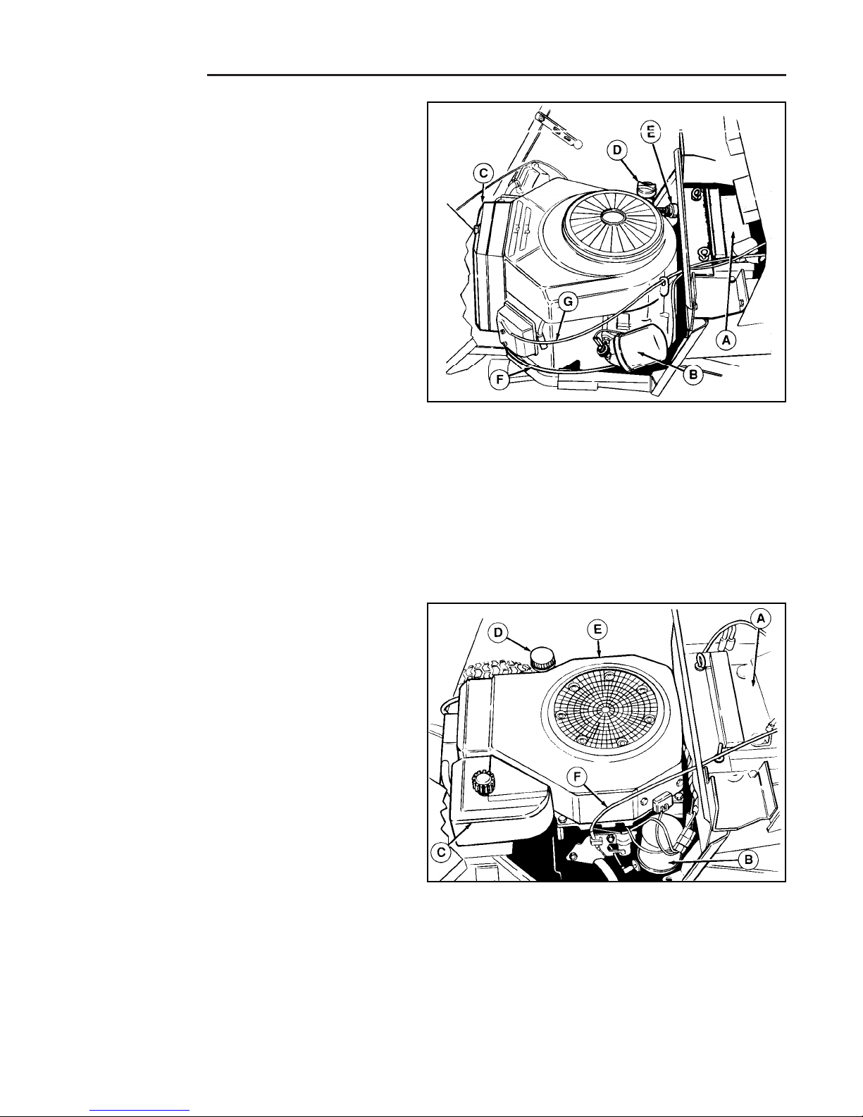
Figure 1. Engine Compartment - 14 / 16HP
Briggs & Stratton Twin Cylinder Engine
A. Battery
B. Oil Filter
C. Air Filter
D Oil Fill/Dipstick
E. Fuel Filter
F. Throttle Cable
G. Choke Cable
Figure 2. Engine Compartment - 14 HP Kohler Single
Cylinder Engine
A. Battery
B. Oil Filter
C. Air Filter
D Oil Fill/Dipstick
E. Fuel Filter
F. Throttle/Choke Cable
Page 25
3 - 5
3 Maintenance
Engine
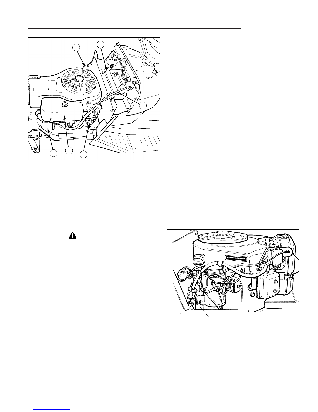
Figure 3. Engine Compartment - 15 HP Briggs &
Stratton Single Cylinder Engine
A. Battery
B. Oil Filter
C. Air Filter
D Oil Fill/Dipstick
E. Fuel Filter
F. Throttle Cable
A
C
B
D
F
E
FUEL FILTER
The fuel filter is located in the engine compartment and
is installed in the rubber fuel line between the fuel tank
and the fuel pump (See Figures 1 through 4). The fuel
filter should be checked every 100 hours of operation, or
sooner and replaced if it appears to be dirty or clogged.
A dirty or clogged filter may cause erratic engine operation, hard starting, or loss of power.
Before removing the hoses from the fuel filter, place a
small container under the filter to catch the gasoline in
the hoses and filter that will drain out as the filter is
removed.
1. Squeeze the tabs on the hose clamps together using
a pliers, and slide the clamps away from the fuel filter.
2. Note the fuel flow direction indicated on the filter, and
remove the filter by pulling the hoses away from the
filter with a twisting motion. Be prepared for fuel in
the hoses and fuel filter to drain out as the hoses are
disconnected, and catch the fuel in the container.
3. Observing the same fuel filter flow direction noted
during removal, install the new fuel filter in the fuel
line by sliding the hoses onto the filter.
4. Squeeze the tabs on the hose clamps together, and
slide the clamps into place over the fuel filter tubes to
secure the fuel lines to the fuel filter.
NOTE: The hose clamps must connect the fuel line
hoses to the fuel filter securely to prevent fuel leakage
and the possibility of engine compartment fire. Replace
the hose clamps if they do not provide a secure, leakproof attachment to the fuel filter.
NOTE: Replace old, brittle, hard, or cracked fuel line.
Figure 4. Fuel Filter Location - Right Side Of
Engine - Twin Cylinder Engine
Fuel Filter
DANGER
Do not remove fuel filter when engine is hot, as
spilled gasoline may ignite. Follow all precautions for the safe handling of gasoline when
removing and installing the fuel filter. DO NOT
spread hose clamps more than necessary.
Replace clamps if they do not provide a secure,
leak-proof attachment to the fuel filter when reinstalled.
Page 26
3- 6
3 Maintenance
Engine / Battery
BATTERY MAINTENANCE
Checking the Battery Fluid
1. Raise the hood.
2. Remove battery filler cap. Fluid must be even with split
ring full mark. If not, add distilled water.
3. Reinstall filler cap.
Cleaning the Battery and Cables
1. Disconnect the cables from the battery, negative
cable first (B, Figure 6).
2. Remove the battery clamp, then remove the battery.
3. Scrub the battery, cables and battery compartment
with baking soda and water.
4. Clean the battery terminals and cable clamps with a
wire brush and battery post terminal cleaner.
5. Reinstall battery and clamp.
6. Connect cables, positive cable first.
7. Coat battery cable clamps and battery terminals with
a protective anti-corrosive coating such as grease or
petroleum jelly.
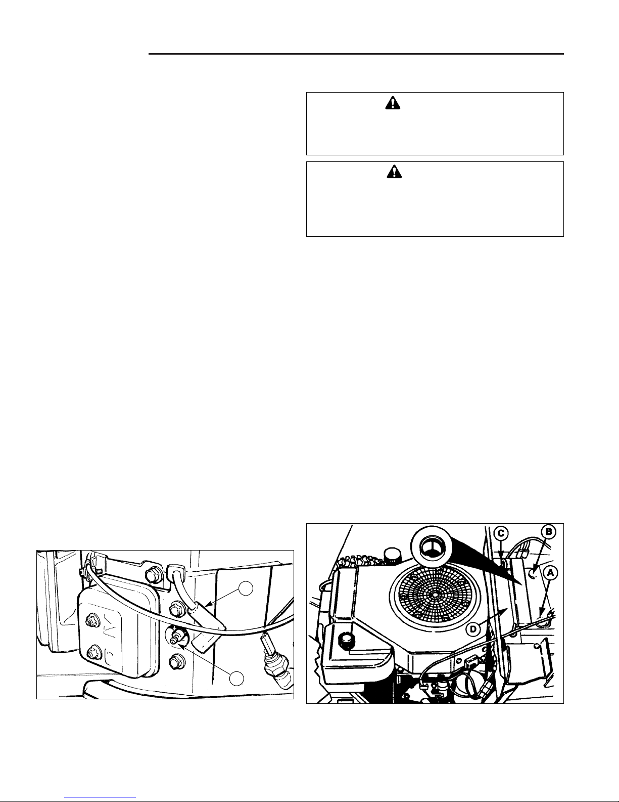
Figure 6. Battery
A. Positive Battery Terminal C. Hold Down Rod
B. Negative Battery Terminal D. Battery Clamp
WARNING
Be careful when handling the battery. Avoid
spilling electrolyte. Keep flames and sparks
away from the battery.
WARNING
When removing or installing battery cables, disconnect the negative cable FIRST and reconnect
it LAST. If not done in this order, the positive terminal can be shorted to the frame by a tool.
SPARK PLUG
The spark plug(s) should be inspected at the regular
intervals specified in the engine manufacturer’s owner’s
manual and cleaned or replaced as required.
Dirty, worn, or fouled spark plugs may cause hard starting, rough engine operation, or loss of power, and may
contribute to premature starter failure from excessive
cranking of the engine.
The spark plug(s) can be found by looking for the thick
black spark plug cable(s) at the engine head, and removing the spark plug boot(s) that connect(s) the cable to the
spark plug.
The spark plug boot can be removed from the spark plug
by pulling the boot away from the spark plug with a slight
side-to-side motion.
To remove the spark plug(s) from the engine for inspection or replacement:
1. Turn the ignition off and remove the key.
2. Raise the hood.
3. Locate the spark plug cable and boot, and pull the
boot off the spark plug (Figure 5).
4. Using a spark plug socket and socket wrench or
equivalent spark plug removal tool, unscrew the
spark plug from the engine by turning the spark plug
counter-clockwise.
5. Inspect the spark plug in accordance with the engine
manufacturer’s instructions, and clean, re-gap, or
replace the spark plug as required.
6. When reinstalling the spark plug, start the plug into
the engine by first turning it clockwise by hand to prevent cross-threading and possible damage to the
spark plug port. Tighten as instructed in engine manufacturer’s manual.
Figure 5. Typical Spark Plug Location
A. Spark Plug
B. Spark Plug Cable & Boot
A
B
Page 27
3 - 7
3 Maintenance
Mower Blade Service
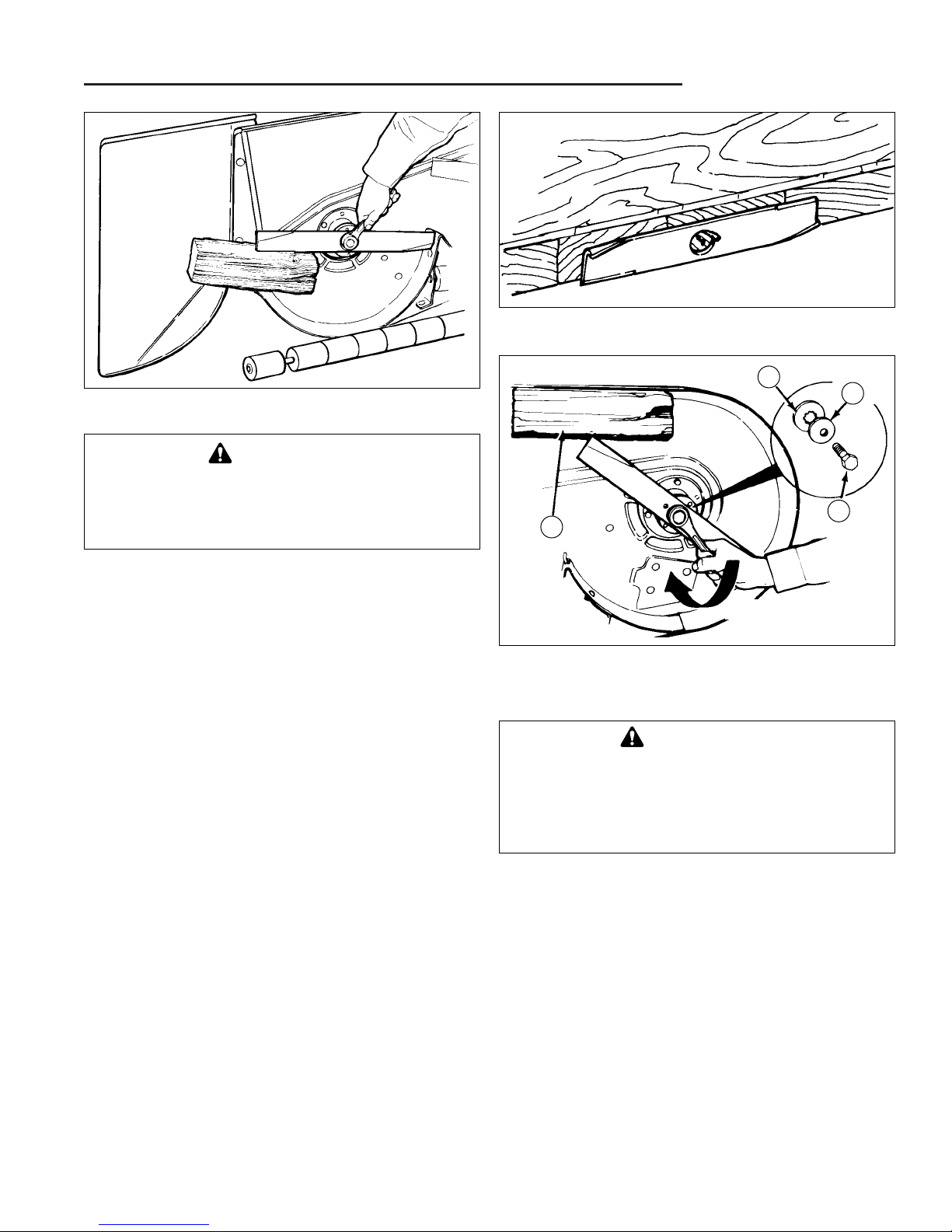
MOWER BLADE SERVICE
1. Remove mower from the tractor. See Operators
Manual.
2. Blades should be sharp and free of nicks and dents.
If not, sharpen blades as described in following steps.
3. To remove blade for sharpening, use wooden block
to hold blade while removing the blade mounting capscrew (Figure 7).
4. Use a file to sharpen blade to fine edge. Remove all
nicks and dents in blade edge. If blade is severely
damaged, it should be replaced.
5. Balance the blade as shown in Figure 8. Center the
blades’ hole on a nail lubricated with a drop of oil. A
balanced blade will remain level.
6. Reinstall each blade with the tabs pointing up toward
deck as shown in Figure 9. Secure with a capscrew
(D), cup washer (C) and spline washer (B). Use a
wooden block to prevent blade rotation and torque
capscrews to 50-70 ft.lbs. (67-95 N.m.).
Figure 7. Removing The Blade
Figure 8. Balancing The Blade
Figure 9. Installing The Blade
A. 4X4 Wooden Block C. Cup Washer
B. Spline Washer D. Capscrew
TIGHTEN
A
B
D
C
WARNING
Blade mounting capscrews must each be
installed with a cup washer and spline washer,
then securely tightened. Torque blade mounting
capscrew to 50-70 ft.lbs. (67-95 N.m.)
WARNING
For your personal safety, do not handle the
sharp mower blades with bare hands. Careless
or improper handling of blades may result in
serious injury.
Page 28
3- 8
3 Maintenance
Lubrication
LUBRICATION
Lubricating the Tractor
Lubricate the tractor as shown in Figures 10 through
17. When a grease gun is shown, wipe the fitting clean,
apply two or three pumps of lithium base automotive
grease, and wipe off excess grease. When an oil can is
shown, wipe the area clean, apply a few drops of SAE 30
weight oil, then wipe up drips or spills.
In general, linkage connections and other parts that have
partial rotational or sliding movement (pedal pivot points,
steering links, etc.) should be lubricated periodically with
SAE 30 weight oil. Avoid applying excessive amounts of
oil since this may cause a build-up of dirt and grass clippings around the lubricated area, making subsequent
lubrication more difficult to accomplish.
Roller bearings, bushings, axles, rotating assemblies
with grease fittings, and mechanisms with exposed gear
teeth (steering gears) require periodic lubrication with
lithium grease.
When grease fittings are present, a manual or pneumatic
pressure-feed grease gun should be utilized to inject
enough grease through the fitting to fully permeate the
enclosed area containing the bearings or other moving
parts.
Plain bushings, bearings, axles without grease fittings,
and exposed gear teeth require the direct application of
grease to all wear surfaces. Use a small, clean applicator
brush or other means of applying and spreading the
grease evenly.
Special care should be taken with ball and roller bearings
to ensure that a liberal application of grease is applied to
the bearing rollers or balls, and both inner and outer
races or bearing and bearing cups.
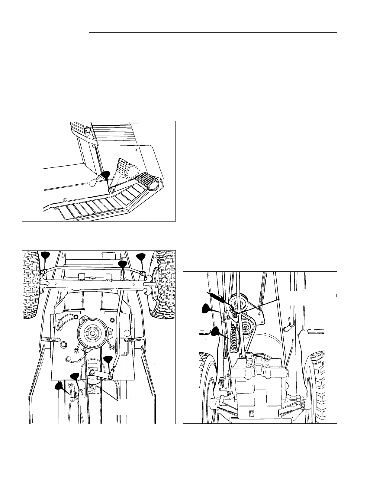
Figure 10. Brake Pedal Pivot Point
Figure 12. Tractor Lubrication Points - Rear Half
(Gear Models)
Apply parking brake
to lube idler pulley.
Lubricate
With Grease
Figure 11. Tractor Lubrication Points - Front Half
Page 29
3 - 9
3 Maintenance
Lubrication
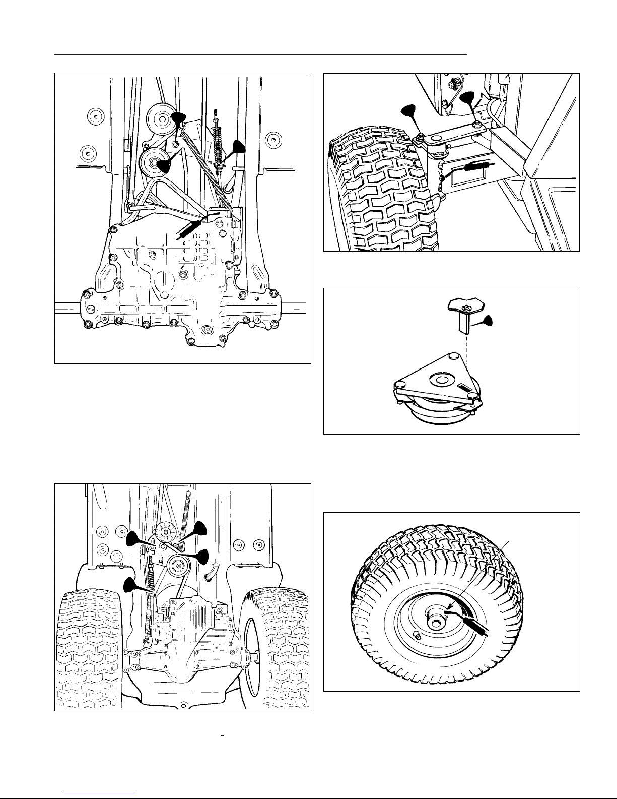
Figure 14. Tractor Lubrication Points - Rear Half
(Later Hydro Models Tuff Torq K60)
Figure 15. Front Axle Lubrication Points
Figure 13. Tractor Lubrication Points - Rear Half
(Early Hydro, Eaton 750/751)
Figure 17. Front Wheel Bushing Lubrication Grease Fitting Location (Inside hub of wheel). Wheel
shown removed from axle for visual clarity.
Front Wheel
Grease
Fitting
Figure 16. PTO (Electric clutch) Lubrication Lubricate tab welded to the underside of frame lightly whenever the electric clutch is removed for service, replaced, or when a squeaking sound develops.
Page 30
Tire Pressure
Front 12-16 psi (82-103 kPa)
Rear 6-8 psi (41-55 kPa)
TIRE PRESSURE
Front and rear tires should be checked periodically to
ensure that proper tire pressure is maintained. Note that
these pressures differ slightly from the “Max Inflation”
stamped on the side-wall of the tire. Keeping the tires
properly inflated to these settings helps provide proper
traction, extend tire life, and improved cut quality.
3- 10
3 Maintenance
Lubrication
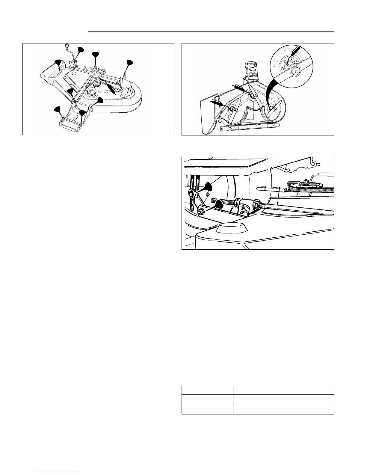
Figure 18. Mower Lubrication Points
Figure 19. Arbor Lubrication Points
LUBRICATING THE MOWER
Lubricate the mower as shown in Figures 20 through 22.
Be sure to include the grease fittings on the mower idler
pulley and arbors, which are located underneath the
mower deck. Always wipe the grease fittings clean
before adding grease to help prevent forcing dirt and
other wear-causing contaminants into the lubrication area.
When oil is indicated, use SAE 30 weight oil. Brush any
dirt and grass from the area to be lubricated, and wipe
lubrication points clean before applying oil. This will
ensure that oil can get into the area where it is required.
Avoid getting grease or oil on belts and pulley when
applying lubricants, and always wipe away excess oil
and grease to prevent a rapid build-up of dirt and debris
from accumulating.
Figure 20. Lubricate Lift Arm Pivot Points
Page 31

4 - 1
4 Adjustments
Table of Contents
SECTION CONTENTS
Electric Clutch Adjustment ......................................... 4-2
Neutral & Return to Neutral Adjustments
Hydro-Gear 311-0750 & 0800Transaxle ........................... 4-3
Eaton 750 Hydrostatic Transaxle
Early Models w/ Welded Support Bracket .................. 4-5
Eaton 750 Hydrostatic Transaxle
Later Models w/ Plastic Support Bracket.................... 4-6
Eaton 751 Hydrostatic Transaxle ...................................... 4-7
Tuff Torq K60 Hydrostatic Transaxle ................................ 4-8
Peerless 801-059B............................................................ 4-9
Clutch / Brake Adjustment
Hydro-Gear 311-0750 & 311-0800.................................... 4-10
Eaton 750/751................................................................... 4-10
Tuff Torq K60 .................................................................... 4-11
Peerless 801 ..................................................................... 4-11
Purging Air From Transaxle ........................................ 4-12
Steering Gear Adjustment ........................................... 4-12
Mower Adjustments ....................................................... 4-13
SECTION 4. ADJUSTMENTS
NOTE: This section contains service information involving minor service procedures and external
adjustments that can be performed without requiring extensive disassembly. See the “REPAIR” section for detailed disassembly and repair information.
Page 32

4 Adjustments
Electric PTO
4 - 2
Electric PTO Clutch
Adjustment
Adjustment of the PTO clutch is usually not necessary on
new units.
1. Remove key from ignition switch and disconnect
spark plug wires to prevent the possibility of accidental starting while the PTO is being adjusted.
2. See Figure 1. Note the position of the 3 adjustment
windows (A) in the side of the brake plate, then rotate
the pulley so that each of the three rivet joints (visible
inside the gap between the pulley and the brake
plate) is positioned approximately midway between
the three adjustment windows.
3. Insert a .012” feeler gauge through each window,
positioning the gauge between the rotor face and the
armature face as shown in Figure 2.
4. With all three feeler gauges in place, alternately tighten the adjustment nuts (B, Figure 1) until the rotor
face and armature face just contact the gauges.
5. Check the gauges for an equal amount of tension
when inserted and removed, and make any necessary adjustments by tightening or loosening the
adjustment nuts.
6. Remove the feeler gauges.
NOTE: The actual air gap between the rotor and armature may vary even after performing the adjustment procedure. This is due to dimensional variations on component parts, and is an acceptable condition.
8. Check the mower blade stopping time. The mower
blades and mower drive belt should come to a complete stop within five seconds after the electric PTO
switch is turned off.
Figure 1. PTO Clutch Adjustment
A. Adjustment Window (Qty. 3, one shown)
B. Adjustment Nut (Qty. 3, two shown)
Rivet
Rivet
Rivet
Window
Adjustment Nut
Figure 2. Feeler Gauge Position
.012”
Feeler
Gauge
(3) Req’d
B
Page 33

4 - 3
4 Adjustments
Neutral Adjustment - Hydro-Gear
NEUTRAL ADJUSTMENT
Broadmoor (Hydro-Gear 311-0750 and 3110800 Transaxle Models)
Perform the following adjustment if the shift lever must
be moved out of the neutral gate to prevent forward or
reverse tractor movement. With the clutch/brake pedal
released, a small amount of travel in the shift lever may
be required to fully stop tractor.
1. Position tractor on flat level ground. Make sure the
ground speed control lever is seated securely in the
neutral gate.
2. Raise the rear of tractor off the ground . See
Elevating Rear End for Safe Service.
3. Loosen nut (A, Figure 3) securing the front shift rod to
the idler pivot assembly (B). The carriage bolt must
be free to move in the shift rod slot.
4. Start the tractor and rotate the hydro cam lever (C)
until rear wheels stop moving. Shut off tractor engine.
5. Tighten nut (A) securely.
6. Check operation of tractor for any movement with shift
lever in neutral gate. Perform the return-to-neutral
adjustment (refer to the following page).
WARNING
When making adjustment, keep hands, hair,
clothing, and tools away from rotating belts.
Grasp cam lever at base to keep hand several
inches below belt rotating around idler pulley
assembly. Careless or improper attention may
result in serious injury.
Figure 3. Neutral Adjustment
A. Nut
B. Idler Pivot Assembly
C. Hydro Cam Lever
Page 34

4 Adjustments
Return-to Neutral - Hydro-Gear
4 - 4
Figure 4. Return-to-Neutral Adjustment
A. Nut
B. Rear Shift Rod
C. Return-to-Neutral Cam
D. Front Clutch Rod
RETURN-TO-NEUTRAL ADJUSTMENT
Broadmoor (Hydro-Gear 311-0750 & 0800
Transaxle Models)
Perform the following adjustment if the shift lever does
not return to the neutral gate when the clutch/brake
pedal is fully depressed.
1. Make sure the Neutral Adjustment is correct (refer to
preceding paragraph).
2. Loosen the nut (A, Figure 4) that secures the rear
shift rod (B) to the return-to-neutral cam (C).
3. Hold the clutch/brake pedal fully down against the
right footrest. Pedal can be clamped in this position
with large C-clamp if required. Do not apply parking
brake as pedal will not be held against footrest without free play.
4. Rotate the return-to-neutral cam (C) securely against
the front clutch rod (D). There should be no gap
between the clutch rod and cam.
5. Tighten nut (A) with pedal held down against footrest.
6. Start tractor and check return-to-neutral operation.
With pedal released, a small amount of travel in the
shift lever may be required to fully stop tractor.
Page 35

4 - 5
4 Adjustments
Neutral Adjustment - Eaton
NEUTRAL ADJUSTMENT
LTH/Broadmoor (Eaton 750 Hydrostatic
Transaxle - Early Models with Welded
Support Bracket “H” - See Figure 5).
NOTE: Perform the Clutch/Brake Adjustment before
doing the Neutral Adjustment.
1. Park tractor on level surface. Shut off PTO switch
and engine. Do not apply parking brake. Make sure
transmission control lever is in neutral and has activated neutral switch light (ignition switch on).
2. Raise the rear of tractor off the ground . See
Elevating Rear End for Safe Service..
3. Loosen nut (A, Figure 5), which secures transaxle
shift rod to speed control lever, (B).
4. Loosen nut (C), which secures the ball retainer (G) to
the welded support bracket.
5. Rotate shift cam (D) so that neutral detent is aligned
with roller ball (E).
6. Start engine and increase to full throttle. If wheels
rotate, continue with adjustment. If wheels do not
rotate, go to step 8.
7. Place a 1/4” rod or #2 Phillips screwdriver into hole
(F) in eccentric ball retainer (G). Rotate ball retainer
until wheels stop moving.
8. Tighten nut (C) securing ball retainer (G).
9. Make sure dash transmission control lever is in neutral position and has activated neutral switch light
(ignition switch) before tightening nut (A).
10. Check the “Return-To-Neutral” by following these
steps:
a. Shift transmission lever into forward (drive) posi-
tion and fully depress clutch/brake pedal.
b. Lever should return to neutral slot.
c. If lever does not return to neutral, repeat above
steps 1 - 9.
11. Shut off engine and remove tractor from jackstands.
Figure 5.
A. Nut
B. Speed Control Lever
C. Nut
D. Shift Cam
E. Roller Ball
F. Adjustment Hole
G. Eccentric Ball Retainer
H. Support Bracket (Welded)
Page 36

4 Adjustments
Neutral Adjustment - Eaton
4 - 6
NEUTRAL ADJUSTMENT
Broadmoor (Eaton 750 Hydrostatic
Transaxle with Plastic Support Bracket “H” See Figure 6).
1. Park tractor on level surface. Shut off PTO switch
and engine. Do not apply parking brake. Make sure
transmission control lever is in neutral and has activated neutral switch light (ignition switch on).
2. Raise rear of tractor off ground with a suitable hoist
or floor jack. Install jackstands underneath transaxle
and block front wheels.
3. Loosen nuts (A, Figure 6) on both left side and right
side of speed control lever (B). (Left side nut is located next to spring and not shown in illustration.)
4. Loosen nut (C) which attaches ball retainer (G) to
plastic support bracket (H).
5. Rotate shift cam (D) so that neutral detent is aligned
with roller ball (E).
6. Start engine and increase to full throttle. If wheels
rotate, continue with adjustment. If wheels do not
rotate, go to step 8.
7. Place a 1/4” rod or #2 Phillips screwdriver into hole
(F) in eccentric ball retainer (G). Rotate ball retainer
until wheels stop moving.
8. Tighten nut (C) securing ball retainer (G).
9. Shut off engine and make sure dash transmission
control lever is in neutral position, and has activated
neutral light (ignition switch on).
10. Pull right end of speed control lever (B) fully forward.
Tighten the left side 1/4” nut (not shown).
11. Push the right end of speed control lever B fully rearward and tighten the right side 5/16” nut (A).
12. Check the “Return-To-Neutral” by following these
steps:
a. Shift transmission lever into forward (drive).
b. Lever should return to neutral slot.
c. If lever does not return to neutral, repeat above
steps 1 - 11, and make necessary adjustments.
d. Recheck following steps 12a - 12c.
13. Remove tractor from jackstands.
Figure 6.
A. Nut
B. Speed Control Lever
C. Nut
D. Shift Cam
E. Roller Ball
F. Adjustment Hole
G. Eccentric Ball Retainer
H. Support Bracket (Plastic)
Page 37

4 - 7
4 Adjustments
Neutral Adjustment - Eaton
NEUTRAL ADJUSTMENT
Broadmoor (Eaton 751 Hydrostatic
Transaxle)
1. Park Tractor on level surface. Shut off PTO switch
and engine, and remove key. Do not apply parking
brake. Make sure transmission control lever is in
neutral and has activated neutral.
2. Raise the rear of tractor off the ground . See
Elevating Rear End for Safe Service.
3. Loosen nuts (A, Figure 7) on both left side and right
side of speed control lever (B). (Left side nut is located next to spring and not shown in illustration.)
4. Rotate shift cam (D) so that neutral detent is aligned
with roller ball (E).
5. Start engine and increase to full throttle. If wheels
rotate, continue with adjustment. If wheels do not
rotate, go to step 9.
6. Loosen nut (C) which secures the ball retainer (G) to
the plastic support bracket (H).
7. Place a 1/4” rod or #2 Phillips screwdriver into hole
(F) in eccentric ball retainer (G). Rotate ball retainer
downward (looking from right hand side) until wheels
rotate forward. Rotate ball retainer slowly upward
(from right hand side) until wheels stop moving.
NOTE: Neutral must be obtained coming from forward.
8. Tighten nut (C) securing b all retainer (G).
9. Shut off engine and make sure dash transmission
control lever is in neutral position against rear edge of
neutral slot in dash.
10. Pull right end of speed control lever (B) fully forward.
Tighten the left side 1/4” nut (not shown).
11. Push the right end of the speed control lever (B) fully
rearward, and tighten right side 5/16 nut (A).
12. Start the engine and run at full throttle. Check for
neutral by moving the control lever into forward and
reverse and back into neutral gate. Control lever can
be moved a small amount forward or backward in
neutral gate to avoid tractor movement. Continue
with adjustments if neutral cannot be obtained.
Figure 7.
A. Nut
B. Speed Control Lever
C. Nut
D. Shift Cam
E. Roller Ball
F. Adjustment Hole
G. Eccentric Ball Retainer
H. Support Bracket
13. Shut off engine. Loosen 1/4” nut at left hand end of
speed control lever. Position transmission control
lever out of neutral slot toward reverse to the point
where notched out portion of lever is even with rear
edge of neutral slot. Pull speed control lever toward
right. Retighten 1/4” nut.
14. Repeat step 12.
15. Shut off engine. Loosen 1/4” nut at left hand end of
speed control lever. Position transmission control
lever out of neutral slot toward reverse to the point
where notched out portion of lever is even with rear
edge of neutral slot. Pull speed control lever toward
right. Retighten 1/4” nut.
16. Repeat step 12.
17. Return-To-Neutral Adjustment is correct when the
above adjustment steps are followed.
18. Remove the unit from the jackstands.
Page 38

4 Adjustments
Neutral Adjustment - Tuff Torq
4 - 8
NEUTRAL ADJUSTMENT
Broadmoor (Tuff Torq K60 Hydrostatic
Transaxle)
NOTE: Perform this adjustment procedure only if tractor
moves forward or reverse when ground speed control
lever is in neutral gate.
1. Place jackstand under each side of rear drawbar.
Adjust jackstand height until rear wheels are off the
ground.
2. Hydro transmission has pre-set internal neutral
adjustment. If tractor creeps when control lever is in
neutral, first loosen nut (A, Figure 8) that attached
shift rod lever (B) to shift pivot assembly (C).
Directional cam (E) will return to factory pre-set
neutral. If wheels continue to move with control lever
in neutral, a problem exists with internal adjustment.
See the repair section of this manual for detailed service instructions. If wheels do not move, perform the
following steps to align cams.
3. Loosen nut (D) securing lever assembly pivot.
4. With nut (A) loosened, make sure ground speed control lever is in neutral slot on dash.
5. Push spring-loaded directional cam (E) side-to-side
and allow cam to return-to-neutral.
6. With cam (E) stationary, move shift pivot assembly
(C) until 1/4” hole in cam and pivot assembly line up.
Insert 1/4” positioning pin F or 1/4” rod through both
parts. Cam (E) must remain in neutral position.
7. With positioning pin in place, tighten nut (D), and then
tighten nut (A).
8. Remove positioning pin and move ground speed control lever through forward and reverse ranges and
return lever to neutral.
9. Check to see if positioning pin can be freely inserted
(from bottom side) through directional cam (E), and
lever assembly (C). If alignment is good, go to step
10. If pin cannot be inserted, repeat steps 2 - 8.
10. With ground speed control lever in neutral position,
start unit (with rear wheels off the ground), and check
for wheel movement. Wheels should not move due
to internal neutral adjustment. If wheels move,
recheck that positioning pin can be inserted freely
through directional cam (E) and lever assembly (C)
with ground speed control lever in neutral position. If
neutral cannot be found, a problem exists with the
unit’s shift linkages.
11. After neutral adjustment, move the ground speed
control lever to forward range and depress the
clutch/brake pedal. The control lever should return to
the neutral position in dash, and wheels should not
move. Move ground speed control lever to reverse
range and repeat check. Return-To-Neutral
Adjustment is correct when the above adjustment
steps are followed.
Figure 8.
A. Nut, 1/4
B. Shift Rod Lever
C. Shift Pivot Assembly
D. Nut, 5/16
E. Cam
F. Positioning Pin
Page 39

4 - 9
4 Adjustments
Neutral Adjustment - Peerless
NEUTRAL ADJUSTMENT
Peerless 801-059B
If the tractor moves forward or backward with the transmission control speed lever positioned in the neutral
gate, perform the following adjustment.
1. Raise the rear of the tractor off ground with suitable
hoist or floor jack. Install jackstands underneath
transaxle and block the front wheels.
2. Start the engine and use the transmission control
speed lever to find neutral, even if control lever is not
in the neutral gate. Shut off engine.
3. See Figure 9. Loosen the nut (A) so that the transmission control rod (B) is free to move.
4. Shift the transmission control lever firmly into the neutral gate on the dashboard. Retighten nut (A).
5. Remove tractor from jackstands.
Figure 9 Neutral Adjustment - Gear Model
A. Nut
B. Transmission Control Rod
Page 40

4 Adjustments
Brake Adjustment
4 - 10
CLUTCH / BRAKE ADJUSTMENT
Brake Spring: Approximate Compressed Spring
Length:
Hydro-Gear 0750/0800 2-7/8”
Tuff Torq K60 2-7/8
Eaton 750 1-3/4
Peerless 801 2-7/8”
Figure 10. Brake Adjustment – Hydro Models
A. Brake Cam D. Brake Rod Spring
B. Transaxle Housing E. Adjustment Nut
C. Adjusting Nut
Figure 12. Eaton 750/751 Clutch/Brake Rod
Adjust nut (A) to provide correct spring length.
Eaton 750 & 751 Transmission
1. Engage the parking brake.
2. The brake spring should be compressed to a length
of 1-3/4”. Turn the adjustment nut (A, figure 12) to
increase or reduce spring tension until the correct
spring length is reached.
A
Hydro-Gear 311-0750 & 311-0800
1. See figure 10. With parking brake released, rotate the
brake cam (A) forward until it stops. There should be
5/16" gap between transaxle housing (B) and rear
point of brake cam.
2. If adjustment is required, remove cotter pin (early
models had an “elastic nut” instead of a cotter pin)
and turn adjusting nut (C) until proper 5/16" clearance
is achieved. Turning the nut in will decrease clearance, and turning the nut out will increase clearance.
Install cotter pin (or nut) after adjustment.
3. Fully depress the clutch/brake pedal and lock the
parking brake by pulling up on the parking brake
knob.
4. The brake rod spring (D) should measure 2-7/8"
when compressed. Turn the adjustment nut (E) as
necessary to obtain correct spring length.
Page 41

4 - 11
4 Adjustments
Brake Adjustment
Figure 13. Tuff Torq K60 Clutch/Brake Rod
Adjust nut (A) to provide correct spring length.
Tuff Torq K60 Transmission
1. Engage the parking brake..
2. The brake spring should be compressed to a length
of 2-7/8”. Turn the adjustment nut (A, Figure 13) to
increase or reduce spring tension until correct spring
length is reached.
A
Peerless 801
1. Place the transmission in gear and release the parking brake.
2. See Figure 11. Move the brake rod (A) back and
forth to be sure there is no tension on the brake pads.
3. Push the cam lever (B) forward (toward front of tractor) to take out any slack. The gap between lever (B)
and stop (C) should be 1/8" (0.3mm). Use a feeler
gauge to measure. if adjustment is required, proceed
to step 4.
4. Loosen or tighten the adjustment nut (D) to obtain the
correct dimension.
5. Fully depress the clutch/brake pedal and lock the
parking brake by pulling up on the parking brake
knob.
6. The brake rod spring should measure 2-7/8" when
compressed. Turn the adjustment nut (E) as necessary to obtain correct spring length.
7. With spring compressed to 2-7/8", adjust set collar (F)
1/4" from brake arm assembly (if present).
Figure 11. Brake Adjustment – Gear Model
A. Brake Rod D. Adjustment Nut
B. Brake Cam Lever E. Spring Adjustment Nut
C. Stop F. Set Collar
2-7/8”
2-7/8”
Page 42

4 Adjustments
Purging Transaxle / Steering Adjustment
4 - 12
STEERING GEAR ADJUSTMENT
If there is excessive back-lash in the steering system, the
steering gear can be adjusted to the steering shaft gear
for better engagement. Refer to Figure 15. Loosen two
capscrews (A) and adjust bracket so that gear teeth are
more closely meshed. Retighten nuts after adjustment.
Figure 15. Steering Gear Adjustment
A. Capscrews
A
PURGING AIR FROM TRANSAXLE
Air may become trapped in the inlet hydraulic filter or
closed loop passages of the hydro transaxle during
assembly or shipment of the tractor. It is very important
for proper operation to release any trapped air that may
cause damage to the internal transaxle parts.
1. Park the tractor on a flat, level surface.
2. Place the hydro release lever (A, Figure 14) in the
“PUSH” position by pulling rearward on the lever. The
lever is located under the rear left-hand corner of the
frame.
3. Start the tractor engine and run at a low idle.
4. Move the ground speed control lever from the neutral
position to the full forward position for five seconds.
Move lever to the full reverse position for five seconds. Repeat this procedure three times in forward
and reverse direction.
5. Return the control lever to the neutral gate.
6. Place the hydro release lever (A) in the “DRIVE” position by pushing lever fully forward.
7. Drive the tractor at least five feet in the forward and
reverse directions with full throttle and full ground
speed. Repeat this procedure three times in the forward and reverse directions.
8. Check oil level (if applicable)
Repeat the above steps if tractor has noisy or erratic
operation, lack of performance after transmission warmup, or oil leakage from the transaxle vent tube.
Figure 14. Release Lever
Release Lever
Page 43

4 - 13
4 Adjustments
Mower Adjustment
MOWER ADJUSTMENT
Leveling The Mower
If the cut is uneven, the mower may need leveling.
Unequal or improper tire pressure may also cause an
uneven cut. Make sure tire pressure is correct as specified in Checking Tire Pressure.
1. With the mower installed, place the tractor on a
smooth, level surface such as a concrete floor. Turn
the front wheels straight forward.
2. Check for bent blades and replace if necessary.
3. Disengage the PTO. Place the mower in mid-cutting
height position. Arrange the mower blades so that
they are pointing from side-to-side.
4. Measure the distance between the outside tips of
each blade and the ground. If there is more than 1/8”
(3mm) difference between the measurements on
each side, proceed to step 5. If the difference is 1/8”
(3mm) or less, proceed to step 6.
5. See Figure 16. Loosen the outside nut (A). Turn the
eccentric nut (B) to raise or lower left-hand side of
mower. When mower is level, hold the eccentric nut
while tightening the outside nut.
TURBO COLLECTION SYSTEM NOTE:
When using a turbo collection system, raise the discharge side of the mower approximately 1/4” to compensate for turbo assembly weight. Check the level of
the cut grass and adjust the 1/4” measurement as
necessary for a smooth, even cut.
6. Arrange the blades so they face front-to-back.
7. On 38" deck, measure the distance from the ground
to front tip of the right blade and from the ground to
the rear tip of the left blade.
On 44" decks, measure the distance from the ground
to the front tip of the center blade, and from the
ground to rear tips of left-hand and right-hand blades.
Front tips on either deck should be 1/4" higher. If not,
proceed with steps 8 - 10.
Figure 16. Leveling The Mower Side-to-Side
A. Outside Nut B. Eccentric Nut
Figure 17. Leveling The Mower Front-To-Back
A. Front Nut C. Mower Bracket
B. Rear Nut D. Adjustment Rod
WARNING
Before checking mower, shut off PTO and
engine. Allow all moving parts to stop. Remove
ignition key, then disconnect the spark plug wire
and fasten it away from the spark plug.
8. See Figure 17. To raise front of mower deck, loosen
front nut (A) and turn rear nut (B) against bracket (C).
9. To lower front of mower deck, loosen rear nut (B) and
bracket (C) will move backwards to lengthen rod.
10. Re-check measurement before tightening front nut
(A) against bracket.
Page 44

4 Adjustments
Notes
4 - 14
Page 45

5 - 1
5 Electrical Troubleshooting
Table of Contents
SECTION 5. ELECTRICAL TROUBLESHOOTING
SECTION CONTENTS
Introduction
Tools Needed .....................................................................................5-2
System Description ............................................................................5-2
Principals Of Operation
Ignition System...................................................................................5-2
Charging System................................................................................5-2
Cranking System ................................................................................5-2
Safety Interlock System......................................................................5-2
Operation............................................................................................5-2
Checking Out The System
General...............................................................................................5-3
Test Series .........................................................................................5-3
Lower Wire Harness Explosion Diagram ...............................5-4
Upper Wire Harness Explosion Diagram................................5-6
1. Checking the Power Supply
A. Wiring.............................................................................................5-8
B. Battery Tests..................................................................................5-8
C. Battery Cables ...............................................................................5-9
2. Isolate Starting and Safety Systems ..................................5-10
3. Checking the Cranking System
A. Test Circuit Breaker .......................................................................5-10
B. Test Power to Ignition Switch.........................................................5-11
C. Test Ignition Switch........................................................................5-11
D. Test Power to Solenoid..................................................................5-12
E. Test Solenoid .................................................................................5-13
F. Solenoid Bench Test ......................................................................5-13
G. Test Power To Starter ...................................................................5-14
4. Test Safety Interlock System
A. PTO Interlock Switch .....................................................................5-15
B. Seat Switch (Mechanical) ..............................................................5-15
C. Seat Switch (Electrical)..................................................................5-16
D. Clutch/Brake Switch (Mechanical) ................................................5-16
E. Clutch/Brake Switch (Electrical)....................................................5-16
F. Neutral Safety Switch (Mechanical) ...............................................5-17
G. Neutral Safety Switch (Electrical) ..................................................5-17
H. Interlock Module ............................................................................5-18
5. Misc. Tests
A. Headlights ......................................................................................5-18
B. Power to Headlights.......................................................................5-18
C. Headlight Switch ............................................................................5-19
D. Hour Meter.....................................................................................5-19
E. Power to Hour Meter......................................................................5-20
F. Inspect and Replace Dash Lights ..................................................5-20
G. Test Electric PTO Clutch ...............................................................5-21
6. Wiring Diagrams..........................................................................5-22
Page 46

5 Electrical Troubleshooting
General Information - Theory
5 - 2
INTRODUCTION
Tools Needed
• VOM (Volt-Ohm meter, multi-meter, or equivalent)
• Test Light.
• Jumper wires with clips at both ends.
Electrical System Changes
Early and later model Broadmoors may have different
electrical components. However, the basic configurations and troubleshooting procedures given in this section still apply. For instance: If the troubleshooting procedure instructs you to test the clutch / brake pedal
switch, and your tractor doesn’t have a clutch / brake
pedal switch, simply skip that step.
System Description
The tractor has four basic electrical systems: ignition,
charging, cranking, and the safety interlock system.
• The ignition system, contained in the engine, is connected through a harness from the magneto to the
ignition switch and interlock module.
• The charging system replenishes lost power to the
battery. The alternator supplies power through a
wiring harness that is connected to a circuit breaker,
and then to the battery.
• The cranking system provides the high energy needed to start the engine. Current is drawn from the battery, through the solenoid, to the starter when the
ignition switch is activated.
• The safety interlock system incorporates safety circuits for safe starting, operation, and shutdown under
unsafe conditions. It consists of the neutral safety
switch, PTO switch, "Operator present" seat switch,
clutch/brake switch, and the interlock module.
PRINCIPALS OF OPERATION
Ignition System
When the ignition switch is turned to OFF, the ignition
circuit closes and grounds the ignition coil stopping the
engine by terminating spark
When the ignition switch is in the RUN position, the ignition circuit is open, allowing the engine to run.
Charging System
While the engine is running, current flows from the alternator through a rectifier to the positive battery post and
charges the battery. The circuit breaker, normally
closed, opens if the circuit is shorted.
Cranking System
Battery voltage is present at the "B" terminal of the ignition switch at all times (see Figure 8). Turning the ignition switch to START supplies 12 volts to one of the solenoid coil terminals. Current is then passed through the
other solenoid coil post to the safety ground circuit. If all
safety switches are closed, the solenoid coil is grounded
engaging the solenoid and sending power to the starter.
If the PTO, transmission, or clutch/brake pedal is
engaged, or if the operator present seat switch is open-the solenoid will not be grounded and the starter will not
crank the engine.
Safety Interlock System
The safety system can be divided into two sub-systems.
The first grounds the engine ignition module if the operator leaves the seat with the transmission engaged or the
PTO engaged.
If the operator leaves the seat, the engine will run only if:
-the PTO is disengaged, AND
-the the parking brake is ON, AND
-the ground speed control lever is in the neutral
gate.
The second sub-system prevents the engine from cranking if the operator is not in the seat with the transmission
disengaged and the PTO disengaged.
The engine will crank only if::
-the operator is in the seat, AND
-the PTO is disengaged, AND
-the clutch / brake pedal is depressed, AND
-the groundspeed control lever is in the neutral
gate.
Operation
If the seat switch system is functioning properly, the following statements are true:
1. The engine will not start unless an operator is in the
seat.
2. The engine will stop running if the operator leaves his
seat while:
a.) the parking brake off, or
b.) the PTO is engaged, or
c.) the ground speed control lever is outside the neutral gate.
3. If the operator is in the seat, the operator can engage
and disengage the transmission and PTO while
engine continues to run.
Page 47

5 - 3
5 Electrical Troubleshooting
General Information - Testing
CHECKING OUT THE SYSTEM
General
Both the ignition and charging systems are internal to the
tractor engine. Follow the Troubleshooting Guide,
Section 2, or refer to your engine manual for information.
See an authorized dealer or appropriate service manual
for additional engine troubleshooting information.
The cranking and safety start systems have interconnected components. The testing of these components
and troubleshooting procedures is covered in detail in
this section.
The testing procedures contained in this section are
intended to be performed as a series. Skipping a step or
leaving it uncompleted can create a dangerous situation
and produce incorrect test results.
Unless otherwise instructed, all tests must be performed
with the ground speed control lever in the neutral gate
with the parking brake engaged, the operator present
seat switch activated, and the PTO switch off.
Reattach components after each test and touch only
points mentioned in the test procedure to avoid possible
damage to testers or components.
Basic Electrical Terms:
“Ground” is the negative battery post or any other conductive part of the frame. For best results, use the negative battery post as ground.
“VOM” is a volt-ohm meter, multi-meter, or equivalent.
“VDC” is volts of direct current or the VOM setting used
to measure DC voltage.
“Ohms” are units of resistance or the VOM setting used
to measure resistance.
“Continuity” is an continuous, unbroken circuit. In this
manual continuity is determined with a VOM set to measure Ohms. Zero Ohms is true continuity. However, due
to contact point corrosion and resistance within wires,
continuity may measure several Ohms.
“No Continuity” is a broken circuit. In this manual no
continuity is determined with a VOM set to measure
Ohms. No continuity will register as infinite Ohms.
“Battery Voltage” is the approximate voltage output of the
battery. Keep in mind that “battery voltage” tested at any
component will be slightly lower than “battery voltage”
tested at the battery terminals due to resistance within
connections and wires.
Test Series
CHECKING THE POWER SUPPLY
1. Wiring
2. Battery Tests
• Check fluid level
• Clean battery and terminals
• Hydrometer (charge) test
• Heavy load test
3. Battery Cables
ISOLATE STARTING AND SAFETY SYSTEMS
CHECKING THE CRANKING SYSTEM
1. Test Circuit Breaker
2. Test Power to Ignition Switch
3. Test Ignition Switch
4 Test Power to Solenoid
5. Test Solenoid
6. Solenoid Bench Test
7. Test Power To Starter
TEST SAFETY INTERLOCK SYSTEM
1. PTO Interlock Switch
2. Seat Switch (Mechanical)
3. Seat Switch (Electrical)
4. Clutch/Brake Switch (Mechanical)
5. Clutch/Brake Switch (Electrical)
6. Neutral Safety Switch (Mechanical)
7. Neutral Safety Switch (Electrical)
8. Interlock Module
MISC. TESTS
1. Headlights
2. Power to Headlights
3. Headlight Switch
1. Hour Meter
2. Power to Hour Meter
1. Inspect and replace Dash Lights
1. PTO Clutch
Page 48

5 Electrical Troubleshooting
Lower Wiring Harness
5 - 4
**2044
8
3
7
9
2
1
15
11
5
13
4
10, 12
16
14
6
To engine fuel shut-off,
jumper wire (Ref. No. 16) used
on 15HP Briggs & Stratton only
Ground to R.H.
front engine
mounting bolt
To oil pressure
sending unit,
Briggs & Stratton
units only.
To oil pressure
sending unit,
Kohler units only.
Kohler units
only
Electric
Clutch
Briggs & Stratton
units only
Grommet - see Hood,
Grille & Dash Group
Kohler units
only
To Upper
Harness
See Engine
Group
To engine fuel
shut-off, Briggs &
Stratton Vanguard only
(not used on single
cylinder engines).
Location of engine
kill wire on
single cylinder
Briggs & Stratton
models only
Location of
engine kill wire
on twin cylinder
Briggs & Stratton
models only
NOTE: Unless noted otherwise, use the
standard hardware torque specification
chart. See Table of Contents.
Figure 1. Lower Wiring Harness
Page 49

5 - 5
5 Electrical Troubleshooting
Lower Wiring Harness
1 1 WIRE ASSY., Headlight
2 2 SOCKET, Bulb
3 2 BULB, Headlight, 12.8V
4 2 TIE, Cable
5 2 BUSHING, Snap, Small
6 1 LENS, Headlight
7 1 BEZEL, Headlight
8 1 HEADLIGHT ASSY. (Incl. Ref. Nos. 2, 3, 6, 7 & 9)
9 2 HEAT SHIELD
10 1 HARNESS ASSY., Lower
(14, 15 & 16 HP Briggs & Stratton)
11 1 WIRE ASSY., Seat Switch
12 1 HARNESS ASSY., Lower (14 & 15 HP Kohler)
13 1 BUSHING, Snap, Large (14 & 15 HP Kohler only)
14 1 WIRE ASSY., Engine Ground
15 1 SWITCH, Seat, Operator Present
16 1 WIRE ASSY., Jumper (15 HP Briggs & Stratton only)
REF.
NO. QTY. DESCRIPTION
LOWER WIRING HARNESS
Page 50

5 Electrical Troubleshooting
Main Wiring Harness
5 - 6
**2045
18
21
8
5
4
11
33
25
34
2
26
12
35
33
15
24
20
1
31
7
6
33
19
14
8
13
33
22
3
32
31
27
28
16
17
9
10
30
29
29
30
Clutch / Brake Pedal
Interlock Switch (Later
Models Only)
Circuit Breaker
Transmission
Switch
Headlight
Switch
To Engine
Starter
To Lower Harness
Not used on 15 HP
Gear Model
Battery groundmount using right
front engine mounting hole
NOTE: Unless noted otherwise, use the
standard hardware torque specification
chart. See Table of Contents.
P.T.O. Switch
23
Figure 2. Main Wiring Harness
Page 51

5 - 7
5 Electrical Troubleshooting
Main Wiring Harness
1 1 COVER, Terminal
2 1 CABLE, Battery to Solenoid
3 1 HOSE, Battery, Drain
4 1 WIRE ASSY.
5 1 CIRCUIT BREAKER
6 1 CABLE, Solenoid to Starter
7 1 HOLD DOWN, Battery
8 5 BULB, Indicator Light (Qty. 4 used on 15 HP models)
9 1 BOOT, Insulator
10 1 BATTERY
11 1 SOLENOID
12 1 IGNITION SWITCH ASSY. (Incl. Ref. Nos. 25, 26 & 35)
13 1 SWITCH, Transmission, Neutral Start
14 1 SWITCH, Headlight
15 1 MODULE
16 1 TRAY, Battery
17 2 NUT, Plastic, 1/4-20
18 1 SWITCH, Interlock, Clutch / Brake Pedal
19 1 STRAP, Wire Retainer
20 2 ROD, Battery Hold Down
21 1 WIRE ASSY.
22 1 CABLE, Battery to Ground
23 1 SWITCH, PTO Electric Clutch
24 1 HARNESS, Upper
25 2 KEY, Ignition
26 1 NUT
27 2 NUT, Hex, Full, 1/4-20 (15 HP models only)
28 2 LOCKWASHER, 1/4
29 2 LOCKWASHER, 5/16
30 2 NUT, Hex, 5/16-24
31 6 WASHER, Plain, 9/32
32 2 CAPSCREW, Hex, 1/4-20 x 3/4
33 7 SCREW, Plastite, #8-16 x 1/2
34 2 SCREW, Plastite, 1/4-20 x 1/2
35 1 LOCKWASHER, Internal Tooth, 5/8
REF.
NO. QTY. DESCRIPTION
MAIN WIRING HARNESS
Page 52

5 Electrical Troubleshooting
Battery & Cable Tests
5 - 8
1. CHECKING THE POWER SUPPLY
A. Check Wiring Condition and Tightness
1. Check all wires for cracked or worn insulation.
2. Check all connectors, terminals, and receptacles for
looseness or corrosion. See Figures 1 and 2.
B. Battery Tests
GENERAL
If the battery is producing 12 volts and the battery cables
have continuity, the rest of the cranking system can be
systematically tested. However, a full test of the battery
includes cleaning, testing battery charge (hydrometer
test) and testing its ability to deliver current (heavy load
test).
NOTE: Before testing, check the battery for any damage
such as a loose post or cracks. Damaged batteries must
be replaced.
CHECK ELECTROLYTE LEVEL
1. Remove the battery vent cap/caps and make sure the
breather holes are open.
2. Check that fluid is even with the bottom of the split
rings (see Figure 3). If not, fill with distilled water.
TEST BATTERY VOLTAGE
1. Test the battery voltage: set VOM to VDC.
2. Place one test probe of the VOM on the battery’s
positive post and one probe on the negative post.
Note and record the battery voltage as it will be referenced in later tests.
HEAVY LOAD TEST
1. Follow the load tester manufacturer's instructions;
connect the battery tester to the battery.
2. Discharge the battery under a fixed load at three
times the ampere-hour rating for approximately 15
seconds, then read the terminal voltage.
Figure 3. Battery Location and Checking Electrolyte
Level
WARNING
TO PREVENT ACCIDENTAL STARTING, DISCONNECT AND SECURE THE SPARK PLUG
WIRES BEFORE CONDUCTING ANY ELECTRICAL TESTS.
WARNING
UNLESS OTHERWISE INSTRUCTED, ALL
TESTS MUST BE PERFORMED WITH THE
GROUND SPEED CONTROL LEVER IN NEUTRAL, THE PARKING BRAKE ENGAGED, AN
OPERATOR IN THE SEAT, AND THE PTO
SWITCH OFF.
CAUTION
REATTACH COMPONENTS AFTER EACH
TEST.
DO NOT PROBE COMPONENTS UNLESS
SPECIFICALLY INSTRUCTED TO DO SO.
TO AVOID A SHORT CIRCUIT AND THE POSSIBILITY OF SPARKS, DO NOT TOUCH THE
TERMINALS EXCEPT AS DIRECTED.
CAUTION
BATTERY ACID CAUSES SEVERE BURNS
Page 53

5 - 9
5 Electrical Troubleshooting
Battery & Cable Tests
Figure 5. Testing Cable Continuity
HYDROMETER TEST
1. Check each cell using a hydrometer.
All cells should have a specific gravity of 1.27 or better.
If the cells vary by more than . 050 points, charge the
battery and recheck.
If one or more cells reads below 1.265 charge at 5 Amps
checking hourly. If the low cell or cells do not improve
within 3 hours of charging, replace the battery.
CLEAN BATTERY
1. Disconnect the negative battery cable, then the positive. See Figure 4.
2. Remove the battery from the battery compartment.
3. Replace the vent cap and remove dirt and corrosion
with a solution of 1 part baking soda and 7 parts
water.
4. Clean the posts with a wire brush until the metal is
shiny.
5. After the battery is reinstalled coat the terminals with
petroleum jelly to prevent corrosion.
C. Clean and Test Battery Cables
NOTE: Be sure to label record where and to which posts
each cable is connected.
1. Remove the negative battery cable from the battery
and from the ground. Clean the cable terminals and
the engine ground with a wire brush until the metal is
shiny.
2. Remove the positive cable from the battery and solenoid. Clean the terminals and solenoid post with a
wire brush until the metal is shiny.
3. Remove the cable going from the solenoid to the
starter. Clean the cable terminals, solenoid post, and
starter post with a wire brush until the metal is shiny.
4. Clean the terminal connecting the circuit breaker to
the solenoid.
5. Set the VOM to Ohms and check the cables for continuity. Replace any cable that has more than 2 Ohms
of resistance or is damaged in any way.
6. Reconnect all cables and terminals to their original
connections.
CAUTION
BATTERY ACID CAUSES SEVERE BURNS
WARNING
FOLLOW BATTERY CHARGER MANUFACTURER’S INSTRUCTIONS.
BATTERY ACID FORMS EXPLOSIVE
GASSES, KEEP FLAMES AND SPARKS
AWAY.
WARNING
ALWAYS DISCONNECT THE NEGATIVE BATTERY CABLE FIRST AND RECONNECT IT
LAST TO PREVENT SPARKS IF THE POSITIVE TERMINAL IS ACCIDENTALLY
GROUNDED TO THE FRAME BY A TOOL
Figure 4. Battery Cable & Hardware Removal
Positive (+)
Negative (-)
Front
Page 54

5 Electrical Troubleshooting
System Isolation / Cranking System Tests
5 - 10
Figure 7. Circuit Breaker Location
A. Circuit Breaker
Figure 6. Isolating the Cranking and Safety System
A. Black/Yellow & Green/Black Connector
2. ISOLATE CRANKING AND SAFETY
SYSTEMS
1. Disconnect the spark plug wire(s) from the spark
plug(s) to prevent accidental starting.
2. Remove the black/yellow and green/black connector
(A, Figure 6) from the small solenoid post.
3. Connect a jumper lead from the small solenoid post
to good ground.
4. With an operator in the seat, the PTO switch off, the
parking brake engaged, and the ground speed control lever in the neutral gate, attempt to crank the
engine.
a.) If the starter turns the engine over, proceed to part
4 TESTING THE SAFETY INTERLOCK SYSTEM.
b.) If the starter does not turn the engine over, proceed to part 3 TESTING THE CRANKING SYSTEM.
5. Remove the jumper and reconnect the black/yellow
and green/black connector to the solenoid.
3. TESTING THE CRANKING SYSTEM
For the following tests it is assumed that the battery is
fully charged and all connections and wires are good.
A. Test Circuit Breaker
The circuit breaker (A, Figure 7) is connected to the posi-
tive post of the battery through the positive battery
cable connected at the large post of the solenoid.
1. Set the VOM to VDC.
2. With the negative probe, touch ground.
3. Touch the positive probe to one post of the circuit
breaker, and then, the other. Both posts should have
close to full battery voltage going to them. If not,
replace the breaker.
4. Set VOM to Ohms.
5. See Figure 8. Probe both circuit breaker terminals. If
the VOM reads 5 Ohms or more, replace the circuit
breaker.
Figure 8. Testing the Circuit Breaker
A
A
Page 55

5 - 11
5 Electrical Troubleshooting
Ignition Switch Tests
Figure11. Testing the Ignition Switch
Figure 9. Ignition Switch Wire Harness (As Viewed
From Engaging End)
Figure 10. Testing the Ignition Switch
B. Test Power to Ignition Switch
1. Pull plug off ignition switch.
2. Set VOM to VDC
3. Probe ground. Probe the "B" receptacle (see Figure
9) on the ignition switch plug. The VOM should show
battery voltage. If not, check the battery, circuit
breaker, and all connections.
4. Reinstall the ignition plug.
C. Test Ignition Switch
1. Remove the plug from the ignition switch.
2. Remove the ignition switch from the dash board.
3. Set VOM to Ohms.
4. With key switch in the OFF position connect test
leads to terminals G and M. There should be a reading of 0.3-3 (continuity) on multi-meter.
5. Check all other connection combinations for no continuity. G to M should be the only combination that
has continuity; all other connection combinations
should have no continuity.
6. With the key switch in the RUN position, connect the
VOM to terminal B and terminal L. There should be a
reading of 0.3-3 Ohms (continuity) on the VOM.
7. Check all other connection combinations for no continuity. B to L should be the only combination that has
continuity; all other connection combinations should
have no continuity.
B
G
L
M
S
M
OFF
G
OFF
B
RUN
START
RUN
START
L
Page 56

5 Electrical Troubleshooting
Ignition Switch / Solenoid Tests
5 - 12
Figure 12. Testing the Ignition Switch
Figure 13. Testing the Ignition Switch
Figure 14. Testing the Ignition Switch
8. Hold switch in START position. Test the following
connections for continuity: B to L, B to S, L to S.
There should be a reading of 0.3-1.0 ohms (continuity) on the multi-meter (see Figures 12-14).
9. Check all other connection combinations for no continuity. B to L, B to S, and L to S should be the only
combinations that have continuity; all other connection combinations should have no continuity.
Replace a switch that does not meet all of the above test
results.
10. Reinstall the ignition switch and reattach the plug.
D. Test Power to Solenoid
1. Unplug the blue / white wire (A, Figure 15) from solenoid post 1 (see Figure 15).
2. Probe ground. Probe the blue / white wire plug.
3. Turn the ignition switch to START. The VOM should
show battery voltage. If not, recheck the key switch,
circuit breaker, and all connections.
Figure 15. Solenoid Location
A. Blue/White Wire & Plug
A
S
B
OFF
RUN
START
OFF
RUN
START
B
L
S
L
OFF
RUN
START
Page 57

5 - 13
5 Electrical Troubleshooting
Solenoid Tests
Figure 18. Testing Solenoid Short
Figure 16. Solenoid Location
A. Green/Black & Black/Yellow Plug
B. Blue/White Plug
Figure 17. Testing Solenoid Resistance
E. Test Solenoid
For this, and all tests, the ground speed control lever
must be in neutral, the parking brake set, and the PTO
switch must be OFF. Unplug and secure all spark plug
wires. Read completely through the instructions before
performing this and all tests.
1. Disconnect the Green/Black & Black/Yellow plug (A,
Figure 16) and Blue/White plug (B, Figure 16) from
the small posts of the solenoid.
2. Connect a jumper lead from one small post to
ground.
3. Connect a jumper lead to the other small post and
then touch it to the positive battery post. The lead
may arch to the battery post–this is normal.
There should be a single audible “click” heard as the
solenoid engages and the engine should turn over. If no
click is heard, proceed to SOLENOID BENCH TEST. If
the solenoid clicks but the starter does not turn the
engine over, check the starter cable and the starter itself.
If the solenoid “clicks” rapidly or repeatedly, recheck the
battery and all connections for corrosion.
F. Solenoid Bench Test
Replace a solenoid that does not pass all of the following
tests.
1. Identify and remove all wires from the solenoid.
Remove the solenoid.
2. Set the VOM to the Ohms setting. Probe the small
posts of the solenoid (Figure 17). The VOM should
read less than 10 Ohms.
3. Connect the VOM probes to the large posts (Figure
18). The meter should read no continuity.
A
B
Page 58

5 Electrical Troubleshooting
Solenoid / Starter Tests
5 - 14
Figure 21. Testing Power to Starter
Figure 19.Testing for Solenoid Short
Figure 20. Testing Solenoid Continuity
4. Probe the mounting base of the solenoid. Probe
small post #1 and observe the VOM. Probe post #2
and observe the VOM. The VOM should read no
continuity in both cases.
5. Apply 12 VDC to the two small posts. There should
be an audible click as the solenoid engages.
6. With the solenoid engaged (12 VDC to the small
posts), measure the resistance at the two large posts.
The VOM should read less than 10 ohms (continuity).
7. Correctly reinstall the solenoid and all related wires
and connectors.
G. Test Power to Starter
For this, and all tests, the ground speed control lever
must be in the neutral gate, the parking brake set, and
the PTO switch must be OFF. Unplug and secure all
spark plug wires.
1. Set VOM to VDC.
1. Probe ground. Pull the boot back and probe the
starter post (see Figure 21).
2. Turn the ignition switch to start.
The VOM should read battery voltage.
12 VDC
Starter Post, Probe Here
Page 59

5 - 15
5 Electrical Troubleshooting
Safety Interlock System Tests
Figure 26. Test Seat Switch (Mechanical)
Figure 22. PTO Switch Testing
A. PTO Switch
4. TESTING THE SAFETY INTERLOCK
SYSTEM
A. Test PTO Interlock Switch
When a switch is replaced, test the new switch to make
sure it works correctly.
1. Turn the PTO switch (A, Figure 22) OFF.
2. Remove the PTO switch wire harness plug.
3. Set VOM to Ohms ( ). Touch one probe to each of
the back row of terminals. The VOM should show no
continuity. (Terminals closer together)
4. Touch one probe to each of the front row of terminals. The VOM should show continuity (Terminals
further apart)
5. Move PTO switch to the ON position.
6. Touch one probe to each of the back row of terminals. The VOM should show continuity
7. Touch one probe to each of the front row of terminals. The VOM should show no continuity.
B. Test Seat Switch (Mechanical)
1. Tilt the seat forward and rest it against the steering
wheel. The switch button should should not be
depressed.
2. Tilt the seat down to operating position and have
someone sit in the seat. The weight of the operator
should depress the switch button.
Seat Switch
Button
Figure 25. PTO Switch Testing
Figure 23. PTO Switch Testing
Figure 24. PTO Switch Testing
Pull-Type Switch
Rocker-Type Switch
A
Page 60

5 Electrical Troubleshooting
Seat Switch / Clutch / Brake Switch Tests
5 - 16
Figure 27. Test Seat Switch (Electrical)
Figure 28. Test Clutch / Brake Switch (Mechanical)
C. Test Seat Switch (Electrical)
1. Raise seat and disconnect the harness plug.
2. Set VOM to Ohms.
3. Connect probes to seat switch terminals. The VOM
should read no continuity.
4. Depress seat switch. The meter should show continuity.
D. Test Clutch / Brake Interlock Switch
(Mechanical, Later Models Only)
1. Release the parking brake.
2. Check the clutch / brake switch. The switch button
should not be depressed.
3. Set the parking brake.
4. Check the clutch / brake switch. The switch button
should be depressed.
E. Test Clutch / Brake Interlock Switch
(Electrical, Later Models Only)
1. Release the parking brake.
2. Remove the plug from the clutch/brake pedal interlock switch.
3. Set the VOM to Ohms and probe the terminals of the
switch. It should read no continuity.
4. Set the parking brake. The VOM should show continuity.
Clutch /
Brake
Switch
Figure 29. Test Clutch / Brake Switch (Electrical)
Clutch /
Brake
Switch
Page 61

5 - 17
5 Electrical Troubleshooting
Neutral Safety Switch Tests
Figure 30. Test Neutral Safety Switch (Mechanical)
Figure 31. Test Neutral Safety Switch (Electrical)
A. Neutral Safety Switch
F. Test Neutral Safety Switch (Mechanical)
NOTE: When a switch is replaced, test the new switch to
make sure it works correctly.
1. Move ground speed control lever out of the neutral
gate.
2. Move ground speed control lever slowly back into the
neutral position while observing switch through the
dashboard. The lever should depress the switch
when in the neutral gate.
G. Test Neutral Safety Switch (Electrical)
NOTE: When a switch is replaced, test the new switch to
make sure it works properly.
NOTE: The neutral safety switch is located under the
dashboard and may be easier to test if removed. Use a
1/4” drive ratchet, a 1” extension, and 1/4” shallow socket to remove the two plastite screws that secure the
switch to the dashboard.
1. Remove the wire harness plug.
2. Place the ground speed control lever in neutral
(depress the switch).
3. Set the VOM to Ohms. Touch one probe to each of
the top row terminals and then the bottom row terminals as shown. With the ground speed control lever
in neutral (switch depressed) both rows should have
continuity.
4. Move the ground speed control lever out of neutral
(switch not depressed).
5. Touch one probe to each of the top row terminals and
then the bottom row terminals as shown in Figure 33.
With the ground speed control lever in forward
(switch not depressed) both rows should have no
continuity.
Neutral Safety
Switch
Figure 32. Neutral Safety Switch Testing
Figure 33. Neutral Safety Switch Testing
A
Page 62

5 Electrical Troubleshooting
Interlock Module / Headlight Tests
5 - 18
Figure 36. Headlight Switch Location
A. Headlight Switch
Figure 34. Interlock Module Location
A. Interlock Module
Figure 35. Headlight Assembly
H. Interlock Module
If all other switches, connectors, wires, and cables have
tested OK, the interlock module is at fault and must
be removed and replaced. The module is not
testable. However, if available, a known-good module can be used to test the system.
1. Unplug and remove the old module (A, Figure 34).
2. Substitute the know-good module for the old module.
3. Turn the ignition switch to START. If the engine turns
over, the old module is bad and must be replaced.
5. MISCELLANEOUS TESTS
A. Test Headlight Bulbs
1. Remove the headlights from the headlight assembly
by twisting the socket counterclockwise and pulling it
out of the reflector assembly.
2. Visually inspect the bulb. If the element is burned
out, replace the bulb.
B. Test Power to Headlight Circuit
1. Turn the ignition switch to ON (RUN) and the headlight switch OFF.
2. Set VOM to VDC. Touch the negative probe to
ground. Use the positive probe to probe the white /
black wire of the headlight switch plug (see Figure
36). The VOM should read battery voltage. If not,
check the ignition switch and all connections and
wires.
3. Turn the headlight switch ON.
4. Probe ground and the white/green plug on the back
of the switch. The VOM should read battery voltage.
If not, check the headlight switch (see TEST HEADLIGHT SWITCH).
A
A
Page 63

5 - 19
5 Electrical Troubleshooting
Headlight / Hour Meter Tests
Figure 39. Hour Meter Location
A. Hour Meter
Figure 37. Test Power to Headlights
Figure 38. Headlight Switch Location
A. Headlight Switch
5. Keep the headlight switch ON. Probe ground and
probe the terminal at the headlight connection. The
VOM should read battery voltage. If not, check the
switch and the continuity of all wires and connectors.
C. Test Headlight Switch
1. Remove the plugs from the headlight switch.
2. Set the VOM to Ohms.
3. With the switch OFF probe both terminals. The VOM
should read no continuity.
4. Turn the switch to ON. The VOM should read continuity.
D. Test Hour Meter (Where Applicable)
The hour meter (A, Figure 39) can be easily tested by
turning the ignition switch to RUN and observing the
meter. The meter should register the passage of time.
Probe Here
A
A
Page 64

5 Electrical Troubleshooting
Hour Meter / Dash Light Tests
5 - 20
Figure 41. Dash Light Assembly Location
A. Dash Lights
E. Test Power to Hour Meter (Where
Applicable)
1. Turn the ignition switch to RUN.
2. Set VOM to VDC.
3. Probe ground. Probe the white/blue wire at the hour
meter terminal. The VOM should read battery voltage. If not, check the key switch and all wires and
connections.
4. Probe ground. Probe the blue/white wire at the hour
meter terminal. The VOM should read battery voltage. If not, check the ignition switch, all wires and
connections, and the hour meter.
F. Inspect and Replace Dash Lights
1. Open the hood.
2. Remove the dash lights (A, Figure 41) by twisting the
socket counterclockwise and pulling it out of the dash
assembly.
3. Visually inspect the bulb and replace if burned out.
Figure 40. Hour Meter Location
A. Hour Meter
A
A
Page 65

5 - 21
5 Electrical Troubleshooting
PTO Clutch Tests
Figure 42. PTO CLutch Terminals
G. Test Electric PTO Clutch
TEST PTO CLUTCH RESISTANCE
1. Set VOM to Ohms.
2. Unplug the PTO clutch connector.
3. Probe PTO clutch connector terminals.
The VOM should read approximately 2-3 Ohms. If the
clutch has more resistance than 3 Ohms, replace the
field assembly or clutch assembly.
TEST ELECTRIC PTO CLUTCH FOR SHORT CIRCUITS
1. Set VOM to Ohms.
2. Probe the clutch body with the negative test lead.
3. Probe one of the connector terminals with the positive lead. The VOM Should show no continuity.
4. Probe the other connector terminal with the positive
lead. Again, the VOM should show no continuity.
If the VOM shows continuity to the clutch body from
either terminal, the clutch has an internal short and
should be replaced.
TEST ELECTRIC PTO CLUTCH ENGAGING
1. Connect the PTO clutch terminals to a 12 VDC power
supply.
An audible “click” should be heard as the clutch
engages. If the clutch does not engage, replace the field
assembly or clutch assembly.
Reconnect the clutch wire connector after testing.
Terminals
Clutch Body
Page 66

5 Electrical Troubleshooting
Wiring Diagram
5 - 22
BLUE
RED / BLACK
WHITE / BLACK
WHITE / BLACK
RED / BLACK
BROWN
BROWN
BROWN / WHITE
BROWN / WHITE
BROWN
RED / WHITE
RED / WHITE
RED / WHITE
ORANGE / BLACK
ORANGE
ORANGE
TAN
TAN
TAN / BLACK
TAN / BLACK
TAN / BLACK
TAN
GREEN
GREEN
GREEN
GREEN / WHITE
GREEN / WHITE
GREEN / WHITE
GREEN / WHITE
BLUE / WHITE
BLUE / WHITE
BLUE / WHITE
BLACK / WHITE
BLACK /
RED
PURPLE / WHITE
PURPLE / WHITE
BLACK / WHITE
BLACK / YELLOW
YELLOW / BLACK
YELLOW / BLACK
GREEN / BLACK
YELLOW
BLACK
BLACK
BLUE
BLUE
SOLENOID
STARTER
ALTERNATOR
HEADLIGHTS
OIL PRESSURE
FUEL
SHUT OFF
16 HP ONLY!
BATTERY
OIL LIGHT
CIRCUIT
BREAKER
IGNITION
SWITCH
FOOT
SWITCH
PTO LIGHT
TRANS. LIGHT
SEAT LIGHT
HEADLIGHT
LIGHT
PTO
SWITCH
TRANS
SWITCH
IGNITION
MODULE
HARNESS
PLUG
(UPPER)
HARNESS
PLUG
(LOWER)
INTERLOCK
MODULE
HEADLIGHT
SWITCH
ELECTRIC
CLUTCH
SEAT
SWITCH
4
1
2
3
4
1
2
3
4
1
23
5
6
7
8
5
6
7
8
56 78
SPLICE "D"
SPLICE "A"
SPLICE "B"
SPLICE "C"
PURPLE
PURPLE
BLACK
BLACK
BLACK
BLACK
BLACK
BLACK
WHITE
WHITE
WHITE
WHITE
RED
RED
RED
RED
RED
B
LA
C
K
LOWER
HARNESS
PTO
START
START
A
LIGHT
C
ED
S
B
M
L
G
S
B
M
L
G
R
S
IGNITION SWITCH
POSITION CIRCUIT MAKE
1.OFF
2. RUN
3. START
G & M
B & L
B & L & S
NOTE:
SPLICE "A" 5.2" FROM HARNESS PLUG.
SPLICE "B" 6.5" FROM HARNESS PLUG.
SPLICE "C" 8.3" FROM HARNESS PLUG.
SPLICE "D" 12.0" FROM HARNESS PLUG.
-
+
UPPER HARNESS
(BACK VIEW
OF SWITCH)
Broadmoor, 1600.
& 1600 Series -
Typical
Page 67

5 - 23
5 Electrical Troubleshooting
Safety System Diagram
BROWN
BROWN / WHITE
BROWN / WHITE
ORANGE / BLACK
TAN / BLACK
TAN / BLACK
TAN / BLACK
GREEN / WHITE
BLUE / WHITE
BLUE / WHITE
BLACK / YELLOW
YELLOW / BLACK
GREEN / BLACK
BLACK
SOLENOID
STARTER
BATTERY
CIRCUIT
BREAKER
IGNITION
SWITCH
FOOT
SWITCH
PTO
SWITCH
TRANS
SWITCH
HARNESS
PLUG
(UPPER)
HARNESS
PLUG
(LOWER)
INTERLOCK
MODULE
SEAT
SWITCH
4
1
2
3
4
1
2
3
4
1
23
5
6
7
8
5
6
7
8
56 78
SPLICE "A"
SPLICE "C"
BLACK
BLACK
BLACK
WHITE
WHITE
RED
RED
RED
B
LA
C
K
LOWER
HARNESS
PTO
START
START
A
LIGHT
C
ED
S
B
M
L
G
S
B
M
L
G
R
S
IGNITION SWITCH
POSITION CIRCUIT MAKE
1.OFF
2. RUN
3. START
G & M
B & L
B & L & S
NOTE:
SPLICE "A" 5.2" FROM HARNESS PLUG.
SPLICE "B" 6.5" FROM HARNESS PLUG.
SPLICE "C" 8.3" FROM HARNESS PLUG.
SPLICE "D" 12.0" FROM HARNESS PLUG.
-
+
UPPER HARNESS
(BACK VIEW
OF SWITCH)
Broadmoor, 1600.
& 1600 Series -
Typical
Page 68

5 Electrical Troubleshooting
Notes
5 - 24
Page 69

6 - 1
6 General Repair
Table of Contents
SECTION 6. GENERAL REPAIR
SECTION CONTENTS
6A. Steering & Front Wheel Repair
General.................................................................................... 6-2
Elevating Front of Unit For Safe Service................................. 6-2
Front Wheel Repair ................................................................. 6-4
LH Spindle Repair ................................................................... 6-6
RH Spindel / Steering Arm Repair........................................... 6-8
Tie Rod Repair ........................................................................ 6-10
Steering Wheel Removal......................................................... 6-12
Steering Shaft Removal .......................................................... 6-13
Steering Gear / Pitman Arm Service ....................................... 6-14
Drag Link Removal.................................................................. 6-15
6B. Hand Controls Repair
General.................................................................................... 6-17
Parking Brake Rod .................................................................. 6-20
Parking / Shift Knob Removal ................................................. 6-20
Shift Lever Assm. Service ....................................................... 6-21
Lift Lever Assm. Service.......................................................... 6-28
Choke Control Service ............................................................ 6-29
Throttle Control Service........................................................... 6-31
6C. Foot Controls Repair
General.................................................................................... 6-33
Clutch / Brake Pedal Arm Assm. Service................................ 6-35
Clutch Rod Service.................................................................. 6-36
Idler Arm Assm. Service.......................................................... 6-40
Lockout Lever Assm. Service.................................................. 6-41
Shift Lever Pivot Assm. Service .............................................. 6-42
Rod Guide / Brake Rod Service .............................................. 6-46
6D. Hood, Grille & Dash Repair
General.................................................................................... 6-51
Hood & Grille Removal............................................................ 6-51
Dash Removal......................................................................... 6-53
6E. Seat, Deck & Fuel Tank Repair
Seat Removal.......................................................................... 6-59
Seat Deck Removal................................................................. 6-60
Fuel Tank Removal ................................................................. 6-60
6F. Rear Wheel Repair
General.................................................................................... 6-61
Elevating Rear End For Safe Service...................................... 6-62
Rear Wheel Removal .............................................................. 6-62
Page 70

6 General Repair
6A Steering & Front Wheel Repair
6 - 2
DANGER
PREVENT SERIOUS INJURY OR
DEATH FROM FALLING UNIT
Always use a properly working lifting device with
a capacity suitable for the weight of the unit
being serviced.
Always use a jack stand to support the unit while
performing service, and chock remaining wheels
to prevent the unit from rolling off the supports.
Never work under or around an elevated unit that
is not properly supported and secured in position with wheel chocks.
Figure A–1. Elevate Front End Of Unit
GENERAL
Servicing the lower steering mechanism and front wheel
spindles should be performed with the front end of the
unit elevated and supported evenly on both sides with
jackstands.
Although service can be performed with the mowing
deck and hood assembly on the unit, removing the deck
and hood assembly provides clear access to all lower
steering mechanism components and helps simplify the
job.
REQUIRED TOOLS & EQUIPMENT
Tools required for performing disassembly and assembly
in these areas include:
• socket wrench set
• open end wrench set
• Flat blade screwdriver
• Metal striking hammer
• Claw hammer, or pry bar
• Center punch or carbide scribe
• Torque wrench (0 - 75 ft. lbs.)
Specialized equipment required for servicing these areas
include:
• Jackstands (2)
• Scissor jack or hydraulic jack
• Wheel blocks (2)
• Grease gun w/Lithium-base automotive grease
• Oil can (use SAE 30 weight oil)
ELEVATING FRONT OF UNIT FOR
SAFE SERVICE
1. Remove the ignition key, and disconnect the spark
plug wire to prevent accidental starting while working
on unit.
2. Remove mowing deck. See Operator’s Manual.
3. Remove the hood assembly as described in Section
6D. Hood, Grille & Dash Repair.
4. Engage parking brake, block the rear wheels, and
using a hydraulic or scissors jack positioned at the
center of the front axle assembly, carefully jack the
unit up until the front tires are approximately 1" - 2"
off the ground (Figure A–1-1).
NOTE: For overall unit stability during service, do not
jack front end higher than required for adequate access
to steering and spindle components. Excessive elevation may result in fuel leakage from gas tank or electrolyte leakage from battery vents.
5. Position jackstands at each end of front axle assembly and lower the unit slowly until jack stands fully
support unit. Make sure the jackstands engage the
bottom of the front axle assembly so that weight is
evenly distributed on each of the jackstands.
6. Check the rear wheel blocks and make sure that they
are tight against the rear wheels to prevent rolling.
DANGER
Do not begin work on the unit unless it is stable
and you are sure wheels are chock to prevent
rolling.
Page 71

6 - 3
6 General Repair
6A Steering & Front Wheel Repair
*AGCO Allis, Massey Ferguson
& early Simplicity models
** Later Simplicity models
A. Valve Stem & Cap
B. Grease Fitting
C. Ring
D. Tube
E. Cap*
F. Retainer*
G. Tire
H. Bearing (See Inset)
I. Wheel
J. Washer
K. Hubcap**
A
G
J
H
B
I
C
K
E
Grease front wheel assemblies
Figure A–2. Front Wheel Assembly
"H" - Later Models
"H" - Early Models
F
D
H
Page 72

6 General Repair
6A Steering & Front Wheel Repair
6 - 4
Figure A–3. Front Wheel Retaining Ring - Broadmoor
Front Wheel Repair
BROADMOOR MODELS
NOTE: Illustrations show AGCO Allis, Massey-Ferguson,
and earlier Simplicity model style of hubcap and hardware. Later model Simplicity units have a large snap-on
hubcap cover that must be removed for access to the
wheel retaining ring.
1. Using a flat blade screwdriver, pop off the plastic hub
cap to gain access to the retaining ring.
2. Insert the tip of the flat blade screwdriver into the
area at the open end of the retaining ring, and twist
the blade against the retaining ring to force the retaining ring out of the groove (Figure A–3).
3. With the retaining ring partially out of the groove,
insert the blade tip between the retaining ring and
spindle shaft, and pop the retaining ring out of the
groove.
4. Slide the wheel off the spindle shaft (Figure A–4).
Note that the tire air valve and axle grease fitting are
located on the inside of the wheel.
5. Removal of the wheel provides an opportunity to
inspect the inside of the tire for sidewall damage, as
well as to check inflation pressure. Also, visually
check wheel bushings for wear or damage before
reinstalling the wheel on the unit, and replace as
required. Wheel bushings are pressed into the wheel
hub with a press fit and may be removed by pressing
or driving out. Align the flat on the bushing with the
grease fitting before pressing in the bushing. When
installing new bushings, measure the I.D. of the
wheel hub to determine the correct bearing O.D. size.
See inset illustration in Figure A–2 for sizes.
Retaining ring
Hubcap
retainer
Figure A–4. Wheel And Assembly Hardware - Broadmoor
A. Air Valve D. Hubcap Retainer
B. Grease Fitting E. Hubcap
C. Retaining Ring
A
C
B
D
E
Page 73

6 - 5
6 General Repair
6A Steering & Front Wheel Repair
Lower Steering Group
Upper Steering Group
Figure A–5. Broadmoor Steering Group - Typical Assembly
(Frame & Dash Shown For Component Position Reference)
Frame
Dash
Lower Dash
STEERING GROUP ASSEMBLIES
Page 74

6 General Repair
6A Steering & Front Wheel Repair
6 - 6
LOWER STEERING GROUP
G
Q
A
B
D
E
F
G
H
H
I
D
E
J
K
K
L
F
C
A
B
P
O
N
M
A. Clip Ring, 5/8
B. Washer
C. Capscrew
D. Spacer
E. Rod End
F. Washer
G. Nut, Flange, 3/8-16
H. Jam Nut, 1/2-20
I. Drag Link
J. Washer, 49/64
K. Spindle Assy.
L. Tie Rod
M. Carriage Bolt
N. Spacer
O. Arm Assy.
P. Nut, Flange Lock, 3/8-16
Q. Steering Arm Assy.
EARLY STYLE DRAG LINK
S. Nut
T. Ball Joint Assy.
U. Nut
V. Drag Link
EARLY STYLE SPINDLE ASSY
W. Key, Hi Pro
X. Set Screw, Sq. Hd.
Torque to
17-23 ft. lbs.
(2 places)
Early Style Drag Link
Figure A–6. Lower Steering Assembly
Figure A–7. Remove Clip Ring
LH Spindle Repair
1. Remove the wheels as described previously under
Front Wheel Repair.
2. Using a flat blade screwdriver, position the tip of the
screwdriver blade at the open end of the steering arm
clip ring, and twist the blade against the clip ring to
force the ring partially out of the groove (Figure A–7).
3. Insert the tip of the screwdriver blade in the gap
between the inside edge of the clip ring and the spindle shaft, and pop the clip ring completely out of the
groove.
NOTE: To index steering
wheel, loosen nuts (H),
adjust drag link (I) so that
full left hand turn and full
right hand turn have
equal play (full turn must
hit spindle stop). Torque
nuts to 13 ft. lbs.
K
K
W
X
*
Early Style Spindle Assembly
* Torque Item "X" to
13-19 ft. lbs. (4 Places)
S
T
U
V
U
Clip Ring
Steering Arm
Assembly
To Pitman Arm
Page 75

6 - 7
6 General Repair
6A Steering & Front Wheel Repair
Figure A–10. Remove Spindle Shaft Bushings
Punch marks
Figure A–8. Remove Rod End
Figure A–9. Inspect Rod End
4. Using a 9/16" socket and 9/16" open end or box
wrench, remove the capscrew/washer and flanged
hex nut that secure the steering arm assembly to the
rod end (Figure A–8).
NOTE: A spacer is located over the capscrew threads in
the rod opening to permit rotation of the steering arm.
Damage to the spacer or washer caused by excessive
tightening or wear may adversely affect steering, so be
sure to inspect these parts and replace them if necessary before reassembly.
5. The rod end is screwed onto the drag link arm and is
secured in place with a 1/2-20 jam nut.
Rod
End
Drag Link
Steering
Arm
Steering
Arm
Rod
End
Steering
Arm
Bushing
6. Inspect the rod end for free movement/rotation of the
rod end bearing, and replace the rod end if necessary
(Figure A–9).
7. To remove the rod end, loosen the jam nut by turning
it clockwise (looking at the end of the drag link shaft)
one or two turns with a 3/4" open-end wrench, and
then unscrew the rod end by turning it counter-clockwise.
NOTE: When reinstalling the rod end, be sure to adjust
the length of the drag link arm so that the left and right
spindle stops stop against the axle assembly with full left
and right turns respectively. See the adjustment procedures section for complete details.
8. Tap the left hand steering arm assembly up off the
spindle shaft with a hammer to remove it from the
axle/spindle shaft assembly.
NOTE: It will be helpful to mark the relative positions of
the steering arm, splined spindle shaft, and shaft housing
with punch marks to simplify realignment later (See
Figure A–10).
9. Tap the top of the splined spindle shaft down with a
few light hammer blows, and remove the spindle
shaft from the bottom of the axle assembly housing,
noting alignment.
10. With the spindle shaft removed, the bushings can be
removed and inspected for signs of wear (Figure
A–10). Use a brass drift or punch to tap out the
bushings from opposite ends of the housing.
Replace the bushings if worn, scored, or cracked.
Page 76

6 General Repair
6A Steering & Front Wheel Repair
6 - 8
RH Spindle/Steering Arm Repair
1. Remove right front wheel using same procedure as
used for left front wheel. (Figure A–11)
2. Use a center punch to mark the relative assembled
positions of the right hand steering arm, right hand
spindle assembly, and the right side of the front axle
assembly (Figure A–11 and A–12).
3.Remove the hex nut and carriage bolt securing the
right hand steering arm to the tie rod (Figure A–12).
Figure A–12. Disassemble Tie Rod From RH Steering
Arm
Figure A–11. Right Front Spindle Assembly
Figure A–13. Remove Retaining Ring
4. Using a flat blade screwdriver, position the tip of the
screwdriver blade at the open end of the steering arm
clip ring, and twist the blade against the clip ring to
force the ring partially out of the groove (Figure
A–13).
5. Insert the tip of the screwdriver blade in the gap
between the inside edge of the clip ring and the spindle shaft, and pop the clip ring completely out of the
groove.
6. Slide the right hand spindle assembly straight down
to remove it from the front axle assembly. Inspect
parts and replace as required. Grease spindle bushings as described earlier in left side disassembly
instructions.
Clip Ring
Page 77

6 - 9
6 General Repair
6A Steering & Front Wheel Repair
Figure A–15. Grease Wheel Bushings
Figure A–14. Lubricate Rod End Spacer
Rod End Spacer
Rod End
Reassembly
1. Reassemble parts in the reverse order of disassembly, using particular care to realign the steering arm
assembly, spindle assembly, and axle housing.
2. Observe torque specifications on Figure A–6.
NOTE: If alignment marks are obscured during service
or if parts are replaced, proper steering alignment can be
performed later with wheels installed using the distance
between tires as a guide. The distance between tires at
the front should be 1/8" less than the distance between
tires at the rear (measured at the the outer edge of the
tire tread) when the wheels are pointed straight ahead.
This slight toe-in is permanently set by the tie rod, and is
not adjustable.
3. Before reassembling rod end hardware to left hand
steering arm, squirt a few drops of SAE 30 weight oil
on the outer surface of the spacer (Figure A–14).
4. Before reinstalling the wheel and related hardware,
grease the spindle bushings using the grease fitting
on the front axle assembly (Figure A–15). Use a lithium-base, automotive-quality grease such as that provided with the optional Grease Gun Kit.
Page 78

6 General Repair
6A Steering & Front Wheel Repair
6 - 10
Tie Rod Repair
1. The tie rod can be removed by disassembling the
flanged hex lock nuts and carriage bolts that secure
the tie rod to the left and right steering arm assemblies (Figure A–16). Use care when removing the
hardware to prevent the internal spacers from falling
out.
2. Check the spacer for signs of excessive wear, damage, or flattening due to over-tightening of the assembly hardware, and replace if required. (The spacer
allows the steering arms to pivot freely at the tie rod
joint.)
3. Check the tie rod for cracks or other damage at the
rod ends, and replace if necessary. Also the center
portion of the tie rod must be straight to provide the
correct center-to-center distance for wheel alignment.
If the tie rod is bent, replace the tie rod.
4. Reassemble the tie rod to the steering arms using
new spacers or hardware if required. Before
installing the flanged lock nut, squirt a few drops of
SAE 30 weight oil around the spacer (Figure A–17).
5. Tighten the lock nut securely, but do not over-tighten
as this will damage the spacer and may prevent free
rotation of the steering arms.
Figure A–17. Lubricate Tie Rod/Steering Arm Spacer
Figure A–16. Tie Rod/ LH Steering Arm Assembly
A. Flanged Hex Lock Nut C. Carriage Bolt
B. Spacer
C
B
A
Spacer
Page 79

6 - 11
6 General Repair
6A Steering & Front Wheel Repair
A. Cap
B. Steering Wheel
C. Pin, 5/16 x 2
D. Tube
E. Steering Shaft
F. Cotter Pin
G. Washer, 49/64
H. Washer
I. Carriage Bolt, 3/8-16 x 1
J. Nut, Flange Lock, 3/8-16
K. Bushing
L. Capscrew, 5/16-18 x 1-1/2
M. Spacer
N. Nut, 5/16-18
O. Capscrew, 3/8-16 x 1-3/8
P. Pitman Arm
Q. Key
R. Screw, Taptite, 5/16-18 x 1
S. Sector Mounting Plate
T. Steering Gear Assy. Hub
U. Square Head Set Screw
UPPER STEERING GROUP ASSEMBLY
I
G
J
K
G
F
E
L
K
T
K
S
R
Q
O
P
N
M
C
D
B
A
NOTE 4
(gear teeth) Apply Loctite
#271. Torque
to 20-30 ft.lbs.
Torque to 17-23
ft.lbs. (2 places)
Early models used a
capscrew, washer & nut
in place of a roll pin (C).
Figure A–18. Upper Steering Assembly
To Rod End - See Figure 4A–8
NOTES:
1. Unless specified, use torque specifications shown on standard hardware torque specification chart.
2. Grease locations indicated by grease gun symbol:
3. Oil locations indicated by oil can symbol:
4. Pitman arm shaft (P) should protrude 9/16" above top of steering gear assembly hub (T).
Grease
bushings "K"
(3 places)
H
U
Page 80

6 General Repair
6A Steering & Front Wheel Repair
6 - 12
Figure A–19. Remove Steering Wheel Hardware
Earlier Models
Steering Wheel Removal
EARLIER MODELS
1A.Remove the steering wheel by disassembling the hex
head bolt and hex nut that secure the steering wheel
to the steering shaft assembly (Figure A–19).
Figure A–20. Remove Steering Wheel Spring Pin
Later Models
Figure A–21. Remove Steering Wheel
CURRENT MODELS
1B.Later-model steering wheels are attached to the
steering shaft assembly with a long spring pin. Use a
pin punch and hammer to drive the spring pin out of
the steering wheel and steering shaft assembly
(Figure A–20).
2. Slide steering wheel up to remove from steering shaft
assembly, and note positioning of mounting holes for
later reassembly (Figure A–21).
3. Inspect steering wheel and hardware for wear or
damage, and replace as required. Reassemble
steering wheel to steering shaft assembly, or proceed
to next step if steering shaft is to be serviced.
Page 81

6 - 13
6 General Repair
6A Steering & Front Wheel Repair
Figure A–22. Remove Cotter Pin
A. Cotter Pin
A
Steering Shaft Removal
NOTE: Unit must eventually be tipped up to remove the
shaft.
1. Remove the steering wheel as shown in the steering
wheel removal section.
2. Remove the cotter pin from the steering shaft (A,
Figure A–22) just above bushing in the frame support.
3. Locate the washers that were held in place by the
cotter pin. Slide the washers off the shaft.
Figure A–23. Steering Mounting Plate
A. Nuts
A
4. Loosen the nuts securing the steering mounting plate
(A, Figure A–23).
5. Slide the steering shaft assembly down and out of
the bottom of the unit to remove for replacement.
Note: Unit must be tipped up at this point to remove
the shaft.
6. Inspect steering shaft assembly and bushings for
excessive wear or damage. Replace if required.
7. Install the steering shaft assembly in the reverse
order of removal and apply a liberal coating of grease
to the steering shaft and drive gear.
Page 82

6 General Repair
6A Steering & Front Wheel Repair
6 - 14
Figure A–26. Remove Steering Arm Assembly
90°
4. Turn the steering arm assembly mounting plate 90*
to allow the assembly to be removed as a unit. Pull the
assembly straight out. See Figure A–26.
5. The steering arm assembly may be disassembled
by removing the the two square head bolts (U, Figure
A–18) from the gear assembly.
6. Inspect all parts for excessive wear or damage and
replace as required.
7. Reassemble in reverse order of disassembly. Apply
a grease to the pitman arm shaft, bushings, and gear
teeth. Note the placement of the shaft key for correct
gear orientation.
Figure A–24. Disconnect Drag Link Ball Joint
Drag Link
Pitman Steering Arm
Steering Gear / Pitman Steering
Arm Service
1. Tilt the unit up or place on an elevated work stand for
access to the underside of the frame.
2. Disassemble the drag link from the pitman arm by
removing the capscrew, washers, spacer, and
flanged hex lock nut (Figure A–24).
Figure A–25. Remove Hex Capscrews
Pitman Steering Arm
3. Remove taptite hex head capscrews that secure pitman steering arm/assembly to underside of unit
(Figure A–25).
Page 83

6 - 15
6 General Repair
6A Steering & Front Wheel Repair
Figure A–27. Disassemble Rod End From Steering
Arm
Figure 4A–29. Disassemble Rear Drag Link Rod End
From Pitman Steering Arm
Drag Link Removal
1. See Figure A–27. Using a 9/16" socket and 9/16"
open end or box wrench, remove the capscrew,
washer and flanged hex nut that secure the steering
arm assembly to the front rod end on the drag link.
(For units equipped with early style drag links, see
Figure A–6 for correct hardware and assembly).
2. Disassemble rear drag link rod end from pitman arm
by removing capscrew, washers, spacer, and flanged
hex lock nut (Figure A–28).
3. Remove the drag link rod ends by first loosening the
jam nuts. Turn the jam nuts clockwise (looking at the
end of the drag link shaft) one or two turns with a 3/4"
open-end wrench, and then unscrew the rod end by
turning it counter-clockwise.
4. Check the drag link for cracks or other damage, and
replace if required. If the drag link is being replaced,
position the jam nuts on the new drag link in the
approximate positions utilized on the old drag link.
5. Inspect the rod ends for free movement/rotation of
the rod end bearing, and replace the rod ends if necessary.
6. Reassemble the rod ends to the drag link, and
reassemble the drag link to the unit in the reverse
order of disassembly. Do not tighten the jam nuts
until final spindle stop adjustments have been made.
NOTE: When reinstalling the rod ends, be sure to
adjust the overall length of the drag link arm so that the
left and right spindle stops stop against the axle assembly with full left and right turns respectively. See the
adjustment procedures section for complete details.
Drag Link
Drag Link
Pitman Steering Arm
Steering Arm
Page 84

6 General Repair
6A Steering & Front Wheel Repair - Notes
6 - 16
Page 85

6 - 17
6 General Repair
6B Hand Controls Repair
GENERAL
The hand controls group consists of the following major
components (also see Figures B–1 and B–2):
• Shift Lever
• Throttle Lever
• Choke Lever
• Parking Brake
• Lift Lever
The hand controls group assemblies can often be serviced without elevating the unit, but servicing these components requires removal of the hood assembly, dash
assembly, and disconnecting several related parts, as
well as disconnecting the battery cables and removing
the battery. In general, removing the mower deck also
makes service access much easier.
Inspecting parts for wear or breakage, or minor service,
such as lubrication or tightening hardware, may, in some
cases, be accomplished by simply removing the steering
wheel and dash attachment hardware, and pulling the
dash assembly up as far as slack in the wiring and control cables permits.
Required Tools & Equipment
Tools required for performing service on the hand controls group include:
• Hammer or rubber mallet
• Small flat blade screwdriver
• Phillips screwdriver
• Long-nose pliers
• 1/2" deep socket
• 3/8" Nut Driver or 3/8" socket w/6" min. extension
• 3/8" & 7/16" box or combination wrenches
• 3/8" & 7/16" open end wrench
DANGER
Always obey all safety precautions for working
around battery hazards such as electrolyte, hydrogen gas, and live battery terminals when removing and reinstalling the battery. Always disconnect the negative terminal cable first, and reconnect it last, to help prevent dangerous sparking caused by accidental tool contact between
the positive terminal of the battery and the
frame. Keep the battery level when handling to
prevent leakage of electrolyte.
Figure B–1. Hand Controls
Throttle
Figure B–2. Hand Controls - Dash View (Steering
Wheel Removed For Clarity)
Shift Lever
Lift Lever
Choke
Shift Lever
Lift Lever
Parking Brake
Page 86

6 General Repair
6B Hand Controls Repair
6 - 18
EARLY MODEL SHIFT LEVER ASSEMBLY
A. Knob
B. Shift Lever
C. Cotter Pin
D. Washer
E. Torsion Spring
F. Plastic Bushing - 1/2" Dia.
G. Nylon Bushing - 3/4" Dia.
H. Tension Bracket
I. Hex Head Capscrew - 5/16-18 x 1-3/4"
J. Washer - 5/16"
K. Spacer
L. Washer - 5/8"
M. Washer - 1/2"
N. Spring
O. Hex Locknut - 5/16-18
P. Shift Lever Assembly
LATER MODEL SHIFT LEVER ASSEMBLY
A. Knob
B. Shift Lever
C. Cotter Pin
D. Washer
E. Torsion Spring
F. Plastic Bushing - 1/2" Dia.
G. Nylon Bushing - 3/4" Dia.
H. Washer - 1/2"
I. Hex Locknut - 5/16-18
J. Washer - 5/16"
K. Spring
L. Hex Nut 5/16-18
M. Lockwasher - 5/16"
N. Washer - H.T.
O. Spacer
P. Stud - 5/16-18 x 3-1/4"
Q. Carriage Bolt 1/4-20 x 3/4"
R. Washer - 21/64 x 1-1/4"
S. Tension Bracket
T. Washer - 1/4"
U. Lockwasher - 1/4"
V. Hex Nut 1/4-20
W. Shift Lever Assembly
Figure B–3. Typical Shift Lever Assemblies
A
B
G
F
E
F
C
D
C
P
L
N
J
O
M
L
K
H
J
I
B
G
F
F
H
C
O
N
M
L
K
J
I
A
E
D
C
W
P
Q
R
S
R
T
U
V
M
Install washer
with rounded
edge down.
Grease
Grease
Grease
Grease
Grease
Grease
Grease
Grease
EARLY MODEL
LATER MODEL
Torque To 75-100 in.-lbs.
L
Page 87

6 - 19
6 General Repair
6B Hand Controls Repair
A. Knob
B. Lift Handle Rod
C. Carriage Bolt - 5/16-18 x 1-1/2"
D. Washer - 13/32 x 1-1/2"
E. Spacer
F. Washer - 5/16"
G. Hex Locknut - 5/16-18
H. Upper Lift Link
I. Upper Transport Lift Link
J. Cotter Pin
K. Lift Link
L. Lift Assembly Cam
M. Washer 21/64" x 1-1/4"
N. Spacer
O. Cotter Pin
P. Washer - 9/32"
Q. Parking Brake Cam
R. Parking Brake Rod
S. Plastic Knob
*T. Lift Handle Rod
*U. Carriage Bolt 5/16-18 x 1"
Figure B–4. Broadmoor Lift Handle Assembly
Early Style Lift
Lever Assembly
A
B
C
D
E
F
G
H
I
J
K
U
D
G
T
L
M
G
N
C
Q
O
P
S
R
Later Style Lift
Lever Assembly
Later Style Lift Lever Assembly
*Early Style Lift
Lever Assembly Only
Lower Dash
Frame
Grease
Page 88

6 General Repair
6B Hand Controls Repair
6 - 20
Shift Knob Removal
3. Remove the shift lever knob from the shift lever as
follows.
a. Plastic knob - unscrews from shift lever by turning
knob counterclockwise.
b. Rubber knob - is pressed onto end of shift lever
and may be removed by placing a 7/16” open end
box wrench under the knob and tapping the
wrench outward with a hammer or rubber mallet.
(Figure B–7) Knobs that resist removal with this
method may be heated with a heat gun or blow
dryer to expand the I.D. of the knob slightly and
separate it from the end of the shift lever.
NOTE: Do not overheat the knob as this may distort the
part or cause melting, and could prevent a secure fit
when reattaching the knob. Use a low heat setting when
using a heat gun, and keep the gun 4-6’’ away from the
knob while moving back and forth to provide even heating.
4.Slide the knob off the shift lever, and check for cracks
or excessive wear, and replace as necessary.
Parking Brake Knob Removal
1. The parking brake rod is threaded. Unscrew the
parking brake knob from the parking brake rod.
(Figure B–6)
WARNING
Never use a heat gun or blow dryer if flammable
vapors are present, as the heating element could
ignite the vapor and cause a fire or explosion.
Figure B–7. Remove Shift Lever Knob (Later Model
With Rubber Knob)
Figure B–6. Unscrew Parking Brake Knob
Shift Lever
Knob
Figure B–5. Remove Cotter Pin From Parking
Brake Rod & Disengage From Brake
Cam
Parking Brake Rod Service
1. See Figure B–5. Remove the cotter pin from the
lower end of the parking brake rod, and after noting
the correct installation position of the rod, disengage
it from the parking brake cam. Lift the parking brake
rod up and out of the lower dash/frame area, and inspect for wear or damage. Replace as necessary.
Reassemble in reverse order of removal.
Cotter Pin
Page 89

6 - 21
6 General Repair
6B Hand Controls Repair
Figure B–8. Broadmoor Hydro Shift/Lift Lever
Access Area
Shift Lever Assembly Service
Shift lever assembly service requires that the dashboard
be removed. Refer to the Hood, Dash, and Grill Repair
section for dashboard removal instructions.
After the dash assembly is fully separated from the unit,
set it aside carefully to prevent damage to electrical components.
The lift lever, and shift lever assemblies are now fully accessible, as is the steering column shaft, and front transmission shift rod connection to the shift lever assembly.
(Figure B–8).
Figure B–9. Adjust Spring Tension
Shift Lever Spring Adjustment
Tension on the shift lever may be increased or decreased by adjusting the tension on the shift lever compression spring (K, Figure B–3 Later Model Shift Lever
Assembly). The correct tension for proper shift lever operation should be obtained when the adjustment locknut
(I, Figure B–3) is torqued to 75 - 100 in./lbs.
1. Using a 1/2 deep socket with a 4" - 6" extension bar,
remove the tension adjustment locknut and compression spring (Figure B–9). Inspect spring and surrounding parts for signs of wear or breakage, and replace as needed.
2. Reassemble parts in position as shown in Figure
4B–4, and torque to 75 - 100 in./lbs.
Figure B–10. Disengage Torsion Spring
Shift Lever Replacement
1. Release tension on the shift lever by disengaging the
torsion spring’s (E, Figure B–3) hooked end from the
shift lever shaft. (Figure B–10)
Torsion
Spring
Tension Spring
Tension Spring
Page 90

6 General Repair
6B Hand Controls Repair
6 - 22
Figure B–11. Remove End Cotter Pin
2. Using a long-nose pliers, remove the cotter pin from
the end of the shift lever. (Figure B–11)
Figure B–12. Slide Shift Lever Out Of Mounting
3. Slide the shift lever out of the shift lever mounting
bushings, and inspect for damage. (Figure B–12)
Replace as necessary.
4. Apply a light application of grease to the end of the
shift lever before reinstalling it into the plastic mounting bushings.
5. Secure the shift lever in place with the cotter pin, and
re-engage the hooked end of torsion spring to the
shift lever.
6. Check the shift lever for smooth operation.
Figure B–13. Shift Lever Assembly Removal
Shift Lever Assembly Replacement
The shift lever assembly should be replaced if damaged
or worn.
1. Remove the steering wheel and steering shaft. See
Steering Wheel Removal and Steering Shaft
Removal sections.
2. From the underside of the unit, remove the two steering gear adjustment locknuts (Figure B–13) that secure the steering mounting plate and lower nylon
bushing to the frame. Removal of the locknuts allows
the two mating carriage bolts to be removed from the
inside, near the base of the shift lever assembly.
3. Disassemble the shift lever and related parts as previously shown in the Shift Lever Service section.
Cotter Pin
Shift Lever
Page 91

6 - 23
6 General Repair
6B Hand Controls Repair
Figure B–14. Disassemble Tension Bracket From
Lower Dash
4. Using a 7/16" socket and a short extension bar, remove the two sets of hex nuts, lockwashers, flat
washers, and carriage bolts that attach the tension
bracket to the inside wall of the lower dash (Figure
B–14).
Figure B–15. Disconnect Shift Rod Linkage From
Shift Lever Assembly Arm
Cotter Pin
Tension Bracket
5.Remove the cotter pin connecting the shift lever assembly arm to the front transmission shift rod linkage
(Figure B–15).
6. The shift lever assembly may now be removed from
the unit and inspected for wear or damage. Replace
parts as required. Refer to Figure B–3 for proper assembly sequence of parts.
7. Reassemble parts in reverse order of disassembly.
Apply a light coating of grease to the inside diameter
of all bushings before reinstalling the shift lever assembly in the unit.
NOTE: On later models with adjustable tension, attach
tension bracket (S, Figure B–3) against lower dash before tightening hex nut (L) on stud (P). Adjust tension on
adjustment nut (I) to 75 - 100 in./lbs.
8. If no additional service is to be performed in this area,
reassemble dash and related parts in reverse order
of disassembly.
9. If lift lever parts are to be serviced, proceed to the Lift
Lever Assembly Service section.
Page 92

6 General Repair
6B Hand Controls Repair
6 - 24
Figure B–16. Front Shift Lever Rod/Shift Lever
Assembly Attachment (Broadmoor
Model Shown)
Shift Lever Rod Service
BROADMOOR LATE MODEL HYDROS
1. Remove battery from unit to provide access to front
shift lever rod assembly at base of shift lever assembly (Figure B–16)
2. Remove cotter pin that secures front shift lever rod to
shift lever arm, and set spacer aside for reuse when
reassembling rod.
Figure B–17. Idler Arm Assembly Area - Underside
Of Unit
3. Safely elevate and support unit (mower deck removed) for working access to idler arm assembly
area and related shift linkage parts (Figure B–17)
Figure B–18. Remove Cotter Pin
4. After noting assembly position of front and rear clutch
rods (to ensure proper assembly when reassembling
parts), remove cotter pin and washer from clutch rod.
5. Disengage the drive spring from the underside of the
frame to release tension on the idler arm assembly,
and remove.
Cotter Pin
Shift Lever
Assembly Arm
Idler Arm
Assembly
Front Shift
Lever Rod
Rear Shift
Lever Rod
Cotter Pin
Washer
Clutch Rod
Page 93

6 - 25
6 General Repair
6B Hand Controls Repair
Figure B–19. Loosen V-Pulley
3. See Figure B–19. Note the position of the belt stop
relative to the v-pulley, and then loosen the lock nut
that secures the v-pulley to the idler. Slide the drive
belt out of the gap between the pulley and belt stop.
Figure B–20. Remove Clip Ring And Idler Arm
Assembly
4. See Figure B–20. Slide the clip ring out of the groove
on the pivot shaft, and remove the idler arm assembly from the unit by pulling it straight out and off the
shaft. (See Foot Controls section 6C for
specific idler arm assemblies and components used
on various models.)
Figure B–21. Lockout Lever/Shift Pivot Assembly
5. See Figure B–21. Remove the hex nut that secures
the lockout lever to the shift pivot assembly. (See
Figure B–21 for complete hardware details.)
6. Lift the rear shift rod off the screw threads and move
it aside, and slide the lockout lever off the pivot shaft.
Belt Stop
Clip Ring
Lockout
Lever
Shift Pivot
Rear Shift Rod
Page 94

6 General Repair
6B Hand Controls Repair
6 - 26
Figure B–23. Disassemble Shift Pivot/Front Shift
Rod Assembly
7. See Figure B–23. Unscrew the hex nut and related
hardware used to connect the shift pivot assembly to
the front shift rod.
8. The shift pivot assembly may now be removed from
the shaft, allowing the front shift rod to be removed.
9. Inspect the shift pivot assembly for wear, corrosion,
or other damage, giving particular attention to the inside surface of the pivot tube. Replace the shift pivot
assembly if worn or corroded.
10. Check the front shift rod for cracks, corrosion, or
other damage, and replace if necessary.
J
L
M
B
B
F
D
C
C
A
F
D
E
INH
G
E
E
K
M
C
B
Figure B–22. Front/Rear Shift Rod Assembly
- Hydro
Parts List
A. Rear Shift Rod
B. Spacer
C. 11/32 x 1-1/8 Washer
D. 5/16 Lockwasher
E. 5/16-18 Hex Nut
F. 5/16 Plain Washer
G. Spacer
H. Control Lever (Transmission)
I. 5/16-18 x 1-3/4 Hex Capscrew
J. 17/32 x 1-1/4 x 5/64 Thk. Washer
K. Cotter Pin
L. Front Shift Rod
M. 5/16-18 x 1-1/4 Carriage Bolt
N. 5/16-18 X 1 Carriage Bolt
Figure B–24. Disassemble Rear Shift Rod From
Transmission Shift Lever
11. If no additional service is required, reassemble parts
in reverse order of assembly, and make neutral and
return-to-neutral adjustments as shown in the adjustments section of this manual.
12. See Figure B–24. If necessary, the rear shift rod may
also be removed and replaced at this point. Remove
the hex nut and related hardware that secure the rear
shift rod to the speed control lever on the transmission.
Front Shift Rod
Shift Pivot
Rear Shift Rod
Page 95

6 - 27
6 General Repair
6B Hand Controls Repair
BROADMOOR GEAR SHIFT ROD - PEERLESS TRANS.
1. Remove battery from unit to provide access to front
shift lever rod assembly at base of shift lever assembly (See preceding Broadmoor Hydro shift rod service section.)
2. Remove cotter pins that secure front shift lever rod to
shift lever arm, and set washers aside for reuse when
reassembling rod.
3. Safely elevate and support unit (mower deck removed) for working access to transmission shift lever
area.
4. See Figure B–26. Remove capscrew, hex nut, washers and spacers connecting shift rod to shift lever,
and remove shift rod from unit. Inspect shift rod for
wear or damage, and replace as required.
5. Reassemble parts in reverse order of disassembly,
applying grease to pivot points as indicated.
6. Adjust transmission as required for proper operation see "Adjustments" section of manual for specific procedures.
G
F
A
F
C
B
I
D
H
J
I
E
Figure B–26. Broadmoor Gear Shift Rod
Peerless Transmission
Parts List
A. Shift Lever
B. 5/16 Washer
C. 5/16 Lockwasher
D. 5/16-18 Full Hex Nut
E. Spacer
F. Washer
G. 5/16 x 1-1/4 Capscrew
H. Shift Rod
I. 1/2 Washer
J. 3/32 x 3/4 Cotter Pin
Figure B–25. Broadmoor Hydro Shift Rod
Eaton Transmission
Parts List
A. 5/16-18 x 1-1/4 Carriage Bolt
B. Speed Control Lever
C. Spacer
D. Plain Washer
E. 5/16 Lockwasher
F. Full Hex Nut
G. Shift Rod
H. 1/2" Washer
I. Cotter Pin
BROADMOOR HYDRO SHIFT ROD - EATON TRANS.
1. Remove battery from unit to provide access to front
shift lever rod assembly at base of shift lever assembly (See preceding Broadmoor Hydro shift rod service section.)
2. Remove cotter pins that secure front shift lever rod to
shift lever arm, and set washers aside for reuse when
reassembling rod.
3. Safely elevate and support unit (mower deck removed) for working access to transmission shift lever
area.
4. See Figure B–25. Remove carriage bolt, hex nut,
washers and spacers connecting shift rod to shift
lever, and remove shift rod from unit. Inspect shift
rod for wear or damage, and replace as required.
5. Reassemble parts in reverse order of disassembly,
applying grease to pivot points as indicated.
6. Adjust transmission as required for proper operation see "Adjustments" section of manual for specific procedures.
I
H
G
A
B
D
C
D
E
F
Page 96

6 General Repair
6B Hand Controls Repair
6 - 28
Figure B–27. Remove Locknut From Lift Handle
Rod Pivot Spacer
Lift Lever Assembly Service
Access for lift lever service may be achieved by removing the battery from the lower dash area, or for a greater
access area, by removing the dash assembly and related
parts as shown in the Hood, Dash, and Grill Repair
Repair section. See Figure B–4 for a complete exploded
view of all parts.
LIFT HANDLE ROD/LINK SERVICE
1. Using a 1/2" socket, remove the locknut securing the
lift handle rod to the pivot spacer inside of the lower
dash (Figure B–27).
Figure B–28. Twist Lift Handle Rod 90° To
Disengage From Upper Lift Link
2. Slide the lift handle rod off the spacer, and twist 90°
to disengage from the upper lift link (Figure B–28).
The lift handle rod can be removed through the slot
in the lower dash. Inspect for wear or damage, and
replace as required.
3. The upper lift link and lift link (H, K, Figure B–4) can
be removed and inspected for wear and damage by
disengaging them from the lift assembly cams under
the unit. Replace links as necessary.
Figure B–29. Remove Upper Transport Lift Link &
Lift Cam
4. See Figure B–29-Top. If necessary, the upper transport lift link can be removed from the lift assembly
cam by removing the cotter pin. Inspect the upper
transport lift link and replace as required.
5. To remove the lift lever cam, use a box wrench and
unscrew the hex nut securing it to the carriage bolt
and unit frame. Inspect for wear or damage, and replace if required. Apply grease to the pivot spacer
during reassembly.
6. Reassemble parts in reverse order of disassembly.
Refer to Figure B–4 for correct part locations.
Page 97

6 - 29
6 General Repair
6B Hand Controls Repair
Figure B–30. Engine Choke Control Location
Engine Choke Control Service
(Twin Cylinder Units Only)
On units with a dash-mounted engine choke control, the
control is a push-pull button mounted on the lower left
portion of the dash assembly (Figure B–30). For easiest
service access, the battery should be removed from the
unit.
Figure B–31. Disconnect Choke Cable At Engine
1. Loosen the choke cable clamp on the engine using a
phillips head screwdriver, and after noting the en-engagement of the cable end with the choke lever, remove the cable end from the choke lever (Figure
B–31).
Figure B–32. Choke Cable Assembly
2. From inside the dashboard area, unscrew the hex nut
that secures the choke cable assembly to the dash,
and slide the choke cable and handle assembly out
of the front of the dash. See Figure B–32.
3. Inspect all parts for wear or damage, and replace as
required.
4. Reassemble parts in reverse order of disassembly.
5. Check the engine choke linkage for proper engagement with the cable and smooth operation of choke.
See the engine manufacturer's instructions for complete choke adjustment instructions.
Engine Choke Control
Choke Cable
Choke Handle
Lockwasher
Hex Nut
To
Engine
Choke Lever
Cable End
Page 98

6 General Repair
6B Hand Controls Repair
6 - 30
Figure B–33. Throttle Control Assemblies
B
C
D
F
N
M
O
THROTTLE CONTROL ASSEMBLY PARTS
A. Throttle Cable
B. Truss head Screw #10-32 x 1/2"
C. Carriage Bolt 5/16-18 x 1-3/4"
D. Throttle Handle
E. Throttle Knob
F. Nylon Washer
G. Throttle Mounting Bracket
H. Washer
I. Esna Light Hex Locknut
J. Plain Washer 5/16"
K. Spring
L. Plastite Screw 1/4-20 x 5/8"
M. Nut Assembly #10-32
N. Bowden Wire Clip
O. Throttle Knob
P. Plastite Screw 1/4-10 x 1/2"
Q. Throttle & Cable Assembly
"One Piece" Throttle Assembly
(Later Models)
"Multi-piece" Throttle Assembly
Throttle (Engine Speed Control)
Throttle (Engine Speed Control) Assembly
G
E
A
F
H
I
L
P
Q
K
J
Page 99

6 - 31
6 General Repair
6B Hand Controls Repair
Figure B–34. Remove Wire Clip & Throttle Cable
From Throttle Lever
Throttle (Engine Speed) Control Service
The throttle control is attached to the underside of the
dashboard and may be accessed by raising the unit's
hood. For greater access and improved work area, the
battery may be removed from the unit.
THROTTLE LEVER TENSION (MULTI-PART LEVER
ASSEMBLY UNITS ONLY)
Note: Later models use a “one piece” non-adjustable
throttle control that is replaced as an assemble.
1. Increase Tension - Tighten the locknut (I, Figure
B–33) by turning clockwise.
2. Decrease Tension - Loosen the locknut (I, Figure
B–33) by turning counterclockwise.
NOTE: When properly adjusted, the throttle lever will
allow positioning with light force, and will maintain the selected position without slippage while the unit is being
operated.
THROTTLE LEVER KNOB REPLACEMENT
1. Remove the throttle lever knob:
a. Round throttle knob - Unscrew the knob from the
throttle lever by turning the knob counterclockwise.
b. "Flat" style knob - Remove the knob by pulling it
straight off the throttle lever.
2. Inspect the knobs for cracks or other damage, and
replace if required.
MULTI-PIECE THROTTLE LEVER ASSEMBLY REPAIR
1. Remove the wire clip securing the throttle cable (N,
Figure B–33) to the throttle lever by removing the
truss head screw and nut assembly (B & M)
2. Disengage the throttle cable from the throttle lever,
and loosely reinstall the screw and nut on the clip to
avoid loss during service (Figure B–34).
3. Remove the throttle lever from the throttle mounting
bracket by unscrewing the hex locknut (I, Figure
B–33) from the carriage bolt (C). (Keep the head of
the carriage bolt against the throttle lever to keep the
bolt from turning while the locknut is being removed.)
4. Slide the carriage bolt and throttle lever out of the
throttle lever mounting bracket, catching the spring
and washers as the carriage bolt is removed from the
assembly.
5. Check the throttle lever mounting bracket (G, Figure
B–33) for wear or damage. Remove and replace if
necessary by unscrewing the three plastite screws
securing the bracket to the underside of the dashboard.
6. Reassemble parts in reverse order of disassembly,
using care to position the nylon washers on both
sides of the throttle lever mounting bracket, and the
metal washers on both sides of the spring , as shown
in Figure B–33.
7. Adjust spring tension to provide secure positioning of
lever while allowing smooth operation of lever.
ONE-PIECE THROTTLE LEVER REPAIR
1. Remove the throttle knob by pulling it straight off the
the throttle lever.
2. Unscrew the plastite screws (P, Figure B–33) securing the one-piece throttle assembly (Q) to the underside of the dashboard, and remove the one-piece
throttle/cable assembly.
3. Inspect the assembly for wear or damage and replace as required. (Consult engine manufacturer's
manual for throttle cable connection to engine throttle
linkage, if necessary.)
4. Reassemble in reverse order of disassembly.
Page 100

6 General Repair
6B Hand Controls Repair - Notes
6 - 32
 Loading...