

Page 1
MODEL LC 3 H.P. TRACTOR
PACKING LIST
The complete tractor is shipped in two cartons. One
contains the frame, wheels, engine and gear case as-
semblies, and the othp.r contains the handles, clutch rods
and levers.
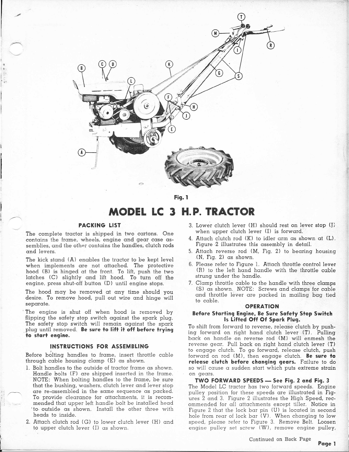
The kick stand (A) enables the tractor to be kept level
when implements are not attached. The protective
hood (8) is hinged at the front. To lift, push the two
latches
engine, press shut-off button (D) until engine stops.
The hood may be removed at any time should you
desire. To remove hood, pull out wire and hinge will
separate.
. The engine is shut off when hood is removed by
flipping the safety stop switch against the spark plug.
The safety stop switch will remain against the spark
.plug unUl removed.
to start engine.
Before bolting handles to frame, insert throttle cable
through cable housing clamp (E) as shown.
1. Bolt handles to the outside of tractor frame as shown.
.to· outside as shown. Install the other three with
2. Attach clutch rod (G) to lower clutch lever (H) and
(C)
slightly and lift hood. To turn off the
Be sure to lift it off before trying
INSTRUCTIONS FOR ASSEMBLING
Handle bolts (F) are shipped inserted in the frame.
NOTE: When bolting handles to the frame, be sure
that the bushing, washers, clutch lever and lever stop
are re-assembled in the same sequence as packed.
To provide clearance for attachments, it is recom-
mended that upper left handle bolt be installed head
heads to inside.
to upper clutch lever (1) as shown.
3. Lower clutch lever (H) should rest on lever stop
when upper clutch lever (I) is forward.
4. Attach clutch rod (K) to idler arm as shown at (L).
Figure 2 illustrates this assembly in detail.
5. Attach reverse rod (M, Fig. 2) to bearing housing
(N, Fig. 2) as shown.
6. Please refer to Figure 1. Attach throttle control lever
(R) to the left hand handle with the throttle cable
strung under the handle.
7. Clamp throttle cable to the handle with three clamps
(S) as shown. NOTE: Screws and clamps for cable
and throttle lever are packed in mailing bag tied
to cable.
OPERATION
Before Starting Engine, Be Sure Safety Stop Switch
Is Lifted Off Of Spark Plug.
To shift from forward to reverse, release clutch by push-
ing forward on right hand clutch lever (T). Pulling
back on handle on reverse rod (M) will enmesh the
reverse gear. Pull back on right hand clutch lever (T)
to engage clutch. To go forward, release clutch, push
forward on rod (M), then engage clutch.
release clutch before changing gears.
so will cause a sudden start which puts extreme strain
on gears.
TWO FORWARD SPEEDS - See Fig. 2 and Fig. 3
The Model LC tractor has two forward speeds. Engine
pulley position for these speeds are illustrated in Fig-
ures 2 and 3. Figure 2 illustrates the High Speed, rec-
ommended for all attachments except tiller. Notice in
Figure 2 that the lock bar pin (U) is located in second
hole from rear of lock bar (V). When changing to low
speed, please refer to Figure 3. Remove Belt. Loosen
engine pulley set screw (W), remove engine pulley,
Be sure to
Failure to do
(J)
Page 2

Identification
•
Groove
Beveled Edge
for Identification
AD AB
~ ..J,;AC
AA
y
y
~d ~
\t'
::IJ
Z R ~
Page 3

Ref.
Letter
A
B
C
D
E
F
G
H
J
K
Part
No.
121139
121107
153094
121118
121163
Description
Lock Plate
Spacer
Shield
Pinion, Reverse
Spacer
121184 Bolt
153106 Cover, Gear Case
153056
8151063
121119
Gear, Drive
Ring, Retainer
Gear Assy., Intermediate
(Available only as two gears,
assembled)
L
121115 Pinion and Pulley Shaft Assy.
M 153078 Bearing, Intermediate Pinion
N
153079 Washer
P
153124
Ring, Retainer
Q 153080 Shaft, Intermediate
725501 Key, Hi-Pro, HP-608
R
153113 Axle
S
153115 Gasket, Gear Case
T
153095
U
153105 Case, Gear
V
153039 Hub, Wheel
W
153088
X
153077
Y
153051 Cage Assy., Ratchet
Z
153093 Spring, Axle
AA
153002 Ratchet
AB
153081
AC
153065
AD
151048.
AE
153008
AF
717513 Nut, Hex, Full, Lock, '/4-20 N.C.
AG
153007
AH
153005
AI
152011 Stand Assy.
AK
152006 Spring, Stand
AL
153006 Pin, Hood
AM
153010
AN
153018 Hood Assy.
AP
AQ 717011
153123 Holder, Belt Stop
AR
AS
8081035
8191047
AT
8021073
AU
153026
AV
151038
AW
AX
8221042
153091 V-Belt, 44"
AY
153151
AZ
727004
BA
BB
8051037
8051505
BC
BD 153069
BE
8151028
Spring, Drag
Washer
Washer, Axle
Spacer
Cover Assy., Ratchet Cage
Latch, Stub
Latch
Bracket Assy. Hood
Pin, Hinge
Spring, Hood
Nut, Hex, jam, 5/16-18 N.C.
Stop, Belt
Spring
Stop, Felt
Screw, Holder
Pulley, Engine
Key, Engine Pulley
Plate, Serial No.
Fitting, Grease, Alemite #1911
Pin, Idler Pulley
Pulley Assy., Idler
Lever Assy., Idler
Extension, Idler Lever
Weight
Lbs.
2
3
5
7
3
1
10
3
4 8
2
4
4
2
7
7
1
2
Oz.
Ref.
Letter
3
3
6
BF 8021073 Stop, Belt
BG 8061058 Spacer, Idler Lever
BH 153108 Housing Assy., Axle
Part
No.
Weiqht
Lbs. Oz.
Bj 153118 Base
6
6
BK 717510 Nut, Hex, Full, Lock,
BL 153073 Spacer, Lock Bar
3/a-16 N.C.
BM 153119 Bar, Lock
BN 153114 Gasket, Bearing Housing
2
8
BP 8161045 Clip, Spring
BQ 153009 Handle
BR 153058 Pin, Lock
BS 717011 Nut, Hex, jam, 5/16-18 N.C.
BT 153116 Pivot
6
2
3
BU 153121 Spring, Reverse Lever
BV 153011 Extension, Spring
BW 153044 .Housing Assy., Bearing
BX 8051038 Bearing
4
8
10
6
BY 727002 Fitting, Grease, Alemite #1641
BZ 153097 Plate
CA 153079 Washer
CB 153124 Ring, Retainer
CC 153096 Pulley, Transmission
CD 725003 Key, Woodruff, #9
4
4
CE 153117 Tube, Rubber
CF 153089 Bearing, AxlE'
CG 8061055 Washer, Retainer
6
8
6
CH 8081503 Clutch Rod, Guide Assy.
Cj 8191045 Spring
CK 8191022 Collar, Set
CL 8061502 Pin Assy., Hitch
10
5
2
CM 153084 Rod, Clutch
CN 153083 Rod, Reverse
CP 153017 Grip, Reverse Rod
CQ 153085 Shaft, Lever
4
6
6
4
3
8
2
8
3
2
8
8
8
2
8
6
I
1
10
12
CR 153074 Guide, Reverse Rod
CS 8021507 Lever Assy., R.H.
eT 8021050 Ball, Clutch Lever
CU 153040 Handle Assy.
CV 153043 Grip, Handle
CW 8061087 Control, Throttle
CX 153087 Wire, Throttle
CY 153086 Cable, Throttle
CZ 8061108 Clip, Throttle
DA 8051506 Lever Assy., L.H.
DB 153082 Rod, Upper Idler
DC8021091! Lever, Lower Clutch
DD 8161215 Busbing
D;
,II
815°120111521
D
r Rod, Lower Clutch
III
Stop, Lever
DG 80611171 Clamp, Cable
DHI8161518ISocket Assy, Rod
Dj
I'
15::'0'4
I
Frame Assy
DK 8261100iHub. Bolt
6
D1. 82620241 Wheel
,---1-.__..__
Page 4

There are four high pressure grease httings on the
tractor, one grease fitting on the idler pulley, one
the main axle housing, one on the gear case and one
on the bearing housing.
designated with letter (G).
ery 4 to 6 hours of use. Grease the main axle housing
every 12 to 15 hours of use. The gear case housing
will require a few shots of grease every 40 to 50 hours
01
use. Lubricate the bearing housing every 5to 6 hours
of operation. Use a general purpose semi-solid grease
Be sure to check level of oil in air filter as recommended
in engine manual.
For shipping purposes, tractor tires are inflated to
approximately 38 lbs. When tractor is assembled and
ready for use, deflate tires to 8 to 10 lbs. of pressure.
They are located in
Grease the idler pulley ev~
TIRE PRESSURt:
Fie).
on
3 aIJd
turn it around and replace with large pulley to outside
as shown in Figure 3.
Make visual alignment of engine, idler and transmission
pulleys, then tighten engine pulley set screw.
Remove spring clip (X) and lock bar pin (U). Pull
transmission slightly to the rear so that pin (U) will enter
rear hole as shown in Figure 3. To facilitate this adjust-
ment, a convenient handle (Y) is provided. Replace
spring clip (X) to hold pin. Replace tractor drive belt.
After changing from one speed to another, adjust set
collar on spring (Z) so spring is compressed approxi-
mately
over center. To avoid damaging belt, use minimum
tension required to drive the tractor. To avoid creeping
and to afford proper declutching of tractor, belt stops
should be adjusted to
is tight.
Miles per hour at rated RPM in each speed:
The tractor but not the engine (see Engine Instruction
Book) is fully lubricated and ready for use when
received.
Sfa"
when clutch lever (T, Fig. 1) is pulled back
!fa"
of the belt when the belt
High .__. .__._..__. .__.. ... __... 2
Low . . ._..__ . 1.5
LUBRICATION
TREAD ADJUSTMENT
Above picture illustrates the position of the mllllmum
and maximum width of the tractor wheels. To obtain
maximum position, remove the hub bolts and wheel
from the hub, and place on opposite side of the tractor.
(Tire is lug type and proper setting of tire lug is neces-
sary for cleaning. Be sure tires are mounted as shown
in illustration).
PATENTED QUICK·HITCH
All front attachments to the tractor use the patented
Quick-Hitch shown above.
INSTRUCTIONS FOR ATTACHING
After loosening T-nuts (A), push the tractor forward until
slots (B) engage at (El between the sideplates and hitch
clamp on the attachment. Push down on the tractor
handles until shaft (el fits in slot Wl. Tighten T-nuts
(Al. To remove attachment, loosen T-nuts (A) suffi-
ciently so side plate can be pulled over catch (X) on
side of frame.
 Loading...