

Page 1

OPERATOR’S
MANUAL
LANDLORD
SOVEREIGN
MFG. NO. 655
MFG. NO. 654
MFG. NO. 657
MFG. NO. 653
Page 2
Safety
.
carefully. Be thoroughly familiar with the
controls and the proper use of fhe equipment.
Never allow children to operate the machine.
Do not allow adults to operate it without
.
proper instruction.
Do not carry passengers.
Keep the area of
persons, particularly small children.and pets.
When using any attachments, never direct
discharge of material toward bystanders nor
allow anyone near the vehicle while in
operation.
Make sure
a. tractor and attachments are in good
operating condition,
b. all safety devices and shields are in place
and in good working
c. all adjustments (cutting height, etc.), have
been made.
Preparation . Handle gasoline with care
it is highly
l
Clear the work area of objects which might
flammable. be picked up and thrown.
a. Use approved gasoline container.
b.
remove the cap of
fuel tank or
add gasoline to a running or hot engine,
Wipe up
spilled gasoline.
l Do not run the engine indoors:‘Exhaust
fumes are dangerous.
l Disengage all attachment clutches and shift
into neutral before attempting to start the
engine.
l
Wear heavy footwear. Do not operate tractor
when barefoot or when wearing open sandals
or
shoes.
l Disengage power to attachments and stop
engine before unclogging attachment chutes.
l Disengage
the
engine before leaving the operatorP position.
.
. Disengage power fo attachment(s) Ind stop the
engine before making any repairs or adjustments. .
. When
the vehicle wirh mower. proceed
as
a. Mow onlv in davliqht or in aood artificial
light.
.
b. Never make a cutting
while the engine is running.
c. Check the blade mounting bolts for proper
tightness at frequent intervals.
l Do not stop or start suddenly when going
uphill or downhill. Mow up and down the face
of steep slopes; never across the face. .
l Reduce speed on slopes and in sharp turns to
prevent tipping or loss of control. Use .
extreme caution when changing direction on
slopes.
l Stay alert fbr holes in The terrain and other
hidden hazards. Be extra careful when
operating on wet or slippery surfaces. .
l The vehicle and attachments should be
stopped and inspected for damage after
striking a foreign objecr. and the damage
should be repaired before restarting and
operating the equipment.
Watch out for traffic when crossing or near
roadways.
If equipment begins to vibrate abnormally
disengage power to atrachments and stop
engine at once. Inspect for damage and correct
before starting up tractor.
Use care when pulling loads or using heavy
equipment.
a. Use only
b. Limit loads to those you can safely control.
c. Do not turn sharply. Use care when backing.
d. Use weights when suggested in the owner’s
manual.
Disengage
to atrachment(s) when
Take all possible precautions when leaving
the vehicle unattended, such as disengaging
the power take-off, lowering the attachment(s).
shifting into neutral,
the parking brake,
stopping the engine. and removing the key.
Keep the vehicle and attachments in good
operating condition, and keep safety devices
in place.
Maintenance
and Storage
. Keep all nuts. bolts, and screws tight to be
l
To reduce fire hazard. keep the engine free of
sure the equipment is in safe working
grass. leaves, or excessive grease.
condition.
l Never
the equipment with gasoline in the
l Do not change the engine governor settings
tank inside a building where fumes may reach
or overspeed the engine.
an open flame or spark. Allow the engine
cool before
in any enclosure.
Page 3
Congratulations on your
of the Simplicity
and garden work easier. You bought the right machine to
do it. So that
chase, we would consider it a personal favor if you would
take time to study this manual before using your tractor
and its attachments. It will increase the chance of adding
you to our long list of satisfied customers. Also, before al-
lowing others to operate your tractor, be
they read
and understand the safety precautions and operation
family and friends, periodically review the safety tips
found on the inside front cover and page two of this man-
SIMPLICITY’S NEW EQUIPMENT WARRANTY
The Company warrants Simplicity products to be free from
in material and workmanship, except
the Company makes no warranty, express or implied, with respect to tires, engines, generators and voltage
regulators, which
warranted by their
manufacturers. Any part
by this warranty which
is
defective within one year (45 days for equipment used for rental, municipal or commercial
purposes) under normal
from date of purchase, will be replaced without charge, provided such
is
returned to the factory, (if requested), and is found to be defective upon examination at the factory. This
does not apply to any Simplicity products altered outside of the Simplicity factory. THE
FOREGOING WARRANTY IS IN LIEU OF ALL OTHER WARRANTIES, EXPR ESS OR IMPLIED. OF
MERCHANTABILITY, FITNESS FOR A PARTICULAR PURPOSE, PERFORMANCE, OR OTHERWISE.
The Company’s obligation under its warranty is
parts,
in no
shall the Company be liable for any other damages, whether direct. immediate,
incidental, special, or consequential. Simplicity Manufacturing Company, Inc.,
the right to modify
description of any Simplicity product.
TABLE OF CONTENTS:..
OWNER’S MANUAL
LANDLORD
SOVEREIGN
MFG. NO. 855
MFG. NO. 854
MFG. NO.
MFG. NO. 653
WARRANTY
SAFETY INFORMATION
FEATURES
OPERATION
CONTROLS AND HOW TO USE THEM
BEFORE STARTING
STARTING THE ENGINE
STOPPING THE ENGINE
CONTROLLING TRACTOR GROUND SPEED
STOPPING
TROUBLE SHOOTING
ADJUSTMENTS
STARTER-GENERATOR
SEAT
SAFETY INTERLOCK
P.T.O. CLUTCH
VARIABLE SPEED DRIVE
HYDROSTATIC TRANSMISSION
BRAKE ADJUSTMENT, FOOT PEDAL
BRAKE ADJUSTMENT, PARKING
MAINTENANCE
EVERY 5 HOURS
EVERY 25 HOURS
EVERY 100 HOURS
SERVICE
GENERAL REPAIRS
OFF SEASON STORAGE
STARTING AFTER STORAGE
REPLACEMENT PARTS
SPECIFICATIONS
ACCESSORIES
1
2
3
4
4
8
9
9
9
10
11
11
11
11
12
12
13
13
14
15
15
15
18
18
18
18
19
19
20
24
1
Page 4

PROTECT YOURSELF AND OTHERS
n Know the controls and how to stop quickly -- READ THE
OWNER’S MANUAL.
. Do not allow children or young teenagers
Ve
. Do not carry passengers. Keep children and pets a safe
distance
. Clear work area of objects which might be picked
and
thrown.
Disengage all clutches and shift into neutral before Starting
engine.
leaving operator position.
n Disengage power to implement
and
engine
making any repairs or adjustments.
. Disengage power to implement
when transporting or
not in use.
. Take precautions, such as disengaging power take-off.
lowering implements, shifting into neutral, setting parking
brake. stopping engine and removing key when leaving vehicle unattended.
n Don’t stop
suddenly when going uphill or downhill.
n Reduce speed on slopes and in sharp turns to prevent tip-
ping or loss of control.
. Stay alert for holes in terrain and other hidden hazards.
n Use care when pulling loads or using heavy equipment.
A. Use only approved
hitch points.
Limit loads to those you can safely control.
C. Don’t turn too sharp, and use care when backing.
D. Use counterweight
or wheel weights when
in owner’s manual.
Watch out for traffic when crossing or near roadways.
n When using any attachments, never direct discharge of ma-
terial toward bystanders nor allow anyone near vehicle
while in
A. Use approved gasoline container.
Never remove cap or add gasoline to a running or
hot engine or fill fuel tank indoors. Wipe up spilled
gasoline.
C. Replace gasoline cap securely.
D. Open doors if engine is run in garage exhaust
are dangerous.
n Keep vehicle and attachments in good operating condition
and keep safety devices in place. Use guards as instructed
in owner’s manual.
Do not operate equipment when barefoot or wearing
sandals. Always wear substantial footwear.
Do not put hands or feet near or under rotetins parts.
Keep clear of discharge opening at all times.
n Before cleaning, inspecting, adjusting, or repairing the trac-
tor or any attachments stop the engine,
the igni-
tion key (electric start models) and be sure all blades and
other moving parts have stopped.
n
Stop blade
when crossing gravel drive, walks or roads.
n After striking a foreign object stop the mower and
the ignition key. Thoroughly inspect the mower for any
damage, and repair the damage before restarting and
operating the mower.
If your equipment should start to vibrate abnormally, stop
the engine and check immediately for the cause. Vibration
is generally a warning of trouble.
Do not run the engine indoors.
n Look to be
that children are not behind the tractor,
before backing up.
n When mowing with a tractor mounted mower, mow
and-down on slopes, never across or horizontally. To prevent the danger of overturning, exercise extreme caution
when stopping, starting or changing direction.
n Check blade and engine mounting bolts for proper tight-
ness at frequent intervals.
n Keep all nuts. bolts, and screws tight to be sure equip-
ment is in safe working condition.
n Never store equipment with gasoline in the tank inside of
a building where fumes may reach an open flame or spark.
Allow engine to cool before storing in any enclosure.
n To reduce fire hazard keep engine free of grass, leaves or
n Never operate any attachment without all guards, deflec-
tors, and other protective covering in place.
n Keep the area of operation
all persons, particularly
small children, and pets.
n Thoroughly inspect the area where the equipment is to be
used and remove all stones, sticks, wiie, bones and other
foreign
objects.
n Check fuel before starting engine. Do not fill gasoline tank
when engine is running or while engine is still hot. Wipe
off any spilled gasoline before starting engine. Do not
smoke when fueling engine or around open gasoline containers.
n Mow only in daylight or in good artificial light.
n Do not change engine governor, settings or overspeed
engine.
Page 5
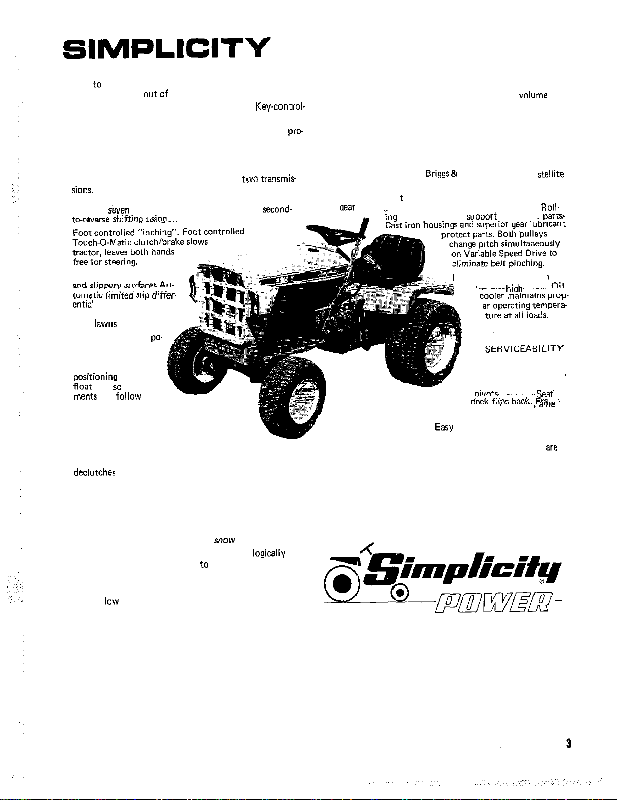
OFFERS YOU-
OPERATION
Easy to get on and off. Full length foot rest is convenient
step. Controls are
the way.
Quick, simple starting. High capacity battery. Key-control-
led electric starter/generator.
Easy steering. Large steering wheel and gear reduction
vide low steering effort.
Simple control of engine speed. Single lever has adjustable
friction lock.
Choice of ground speed control. Pick from
Hydrostatic Drive for full range of ground speeds in
forward or reverse without clutching. Variable Speed Drive
provides
speeds in each gear plus flip shift
shiftinn
clutch.
Comfortable foot support Large area foot rests permit
changing foot position without resting feet on mower.
Reduced noise and vibration, Enclosed, large
muffler lowers engine noise. Synchro-balanced engine
(Sovereign) and massive frame (Sovereign and Landlord)
minimizevibration.
RELIABILITY
Increased engine life.
Stratton engine has
valves with rotators.
Durable power t
rain. Transmission differential and bevel
housing are all of hardened gear construction. Roll-
Good traction on sidehills
At,.
provides traction on
sidehills and ice, yet doesn’t
scuff
on turns.
Precise attachment po-
sitioning. Standard
manual lift has notched sector for fixed
cam
attach-
can follow
ground contour.
SAFETY
Single action stopping. Large clutch/brake
pedal has outer lip, retains foot even when icy;
in first half of travel and applies brake
when depressed further.
Protection from hazardous parts. Belts and drives are
shielded. Muffler and exhaust pipe are enclosed by hood
and grill.
Unobstructed view. Low profile hood. Headlights illumi-
nate wide area, do not reflect from
thrower.
Easily identified control action. Controls are logicallv
grouped and clearly marked as to function and direction.
COMFORT
Soft, comfortable ride. Double bead rim wheels retain
tires at
air pressure.
Comfortable Seat. Position is adjustable to match opera-
tor’s size.
Hydrostatic transmission
handler
loads,
Simple access to en-
gine and power train.
Hood unlatches and
forward.
is open at bottom.
to change oil. Optional e-
lapsed time meter indicates when oil
change is required. Oil fill and drain pipes
readily accessible.
No fuse replacement, Automatic reset circuit breaker
eliminates fuses.
Differential needs no adjustment. Eight springs and hard-
ened wear plates automatically adjust limited slip action.
EQUIPMENT
Page 6

OPERATION
CONTROLS AND HOW TO USE THEM
Picture yourself seated on your Landlord or Sovereign
tractor. ‘Before starting the engine, lets learn how to use
each of the safe, easy to reach controls. (The numbers on
figures
1 thru 7 correspond to the paragraph numbers be-
low.
1. Ignition Switch: When turned clockwise to the first po-
sition, the ignition is turned “ON”. Turn past the “ON”
position to
the starter. (If the starter does not ac-
tuate, be sure the transmission shift lever on variable speed
or the hydrostatic control lever on hydrostatic
models is in the neutral position). Release the key as
as the engine starts. Return the key to the vertical position
to stop the engine. ALWAYS REMOVE THE IGNITION
KEY WHEN CLEANING, ADJUSTING OR
THE TRACTOR OR ANY ATTACHMENT OR WHEN
LEAVING THE VEHICLE UNATTENDED.
FIGURE 1
2. Engine Speed Control Lever. The engine speed control
lever should be moved forward toward the FAST position
to increase engine speed and back toward the SLOW position to decrease engine speed.
3. Choke Control Knob: Pull the choke control knob all
the way out when starting the engine. As
as the en-
gine starts, push the control knob all the way in. The
4
choke control should be pushed all the way in whenever
the engine is running.
4. Generator Warning Light: The generator light will
you if the generator or voltage regulator on your tractor is
not functioning properly. It is normal for the generator
light to come on when the ignition switch is in the ON position and the engine is stopped
The light should go out when the engine is running at
higher speeds. If it does not, the generator a voltage regulator, is not functioning properly. Check the generator
belt adjustment (see
dealer if the light will not go out after the belt is adjusted.
FIGURE 2
5. Light Switch: (Standard equipment on Sovereign
Optional on Landlord). Place the toggle switch in the “UP”
position to turn on lights. To avoid the battery being
cidentally run down, the ignition switch must also be in
the “ON” position for the lights to work. DO NOT OPER-
Page 7
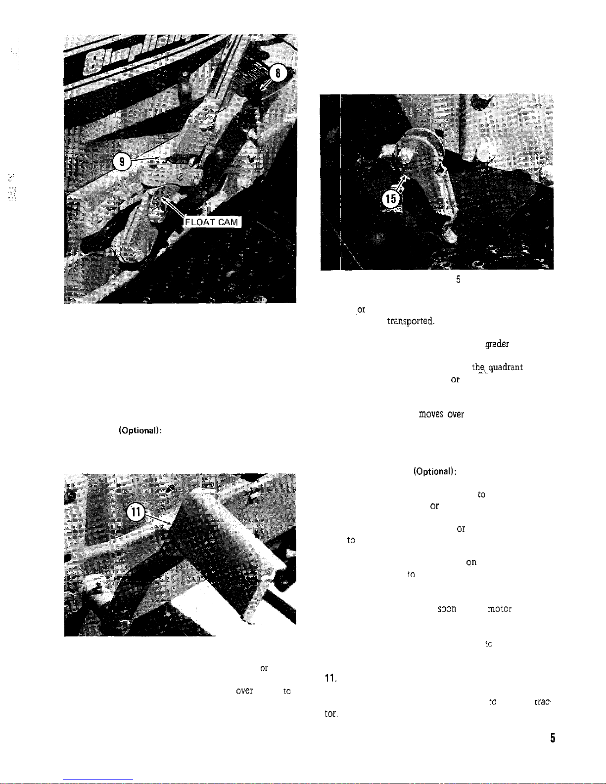
FIGURE 3
ATE THE LIGHTS FOR OVER 10 MINUTES WHEN
THE GENERATOR LIGHT IS ON OR THE BATTERY
MAY DISCHARGE ENOUGH SO IT WILL NOT START
THE ENGINE.
6. Fuel Gauge and Filler Cap: The gauge measures the level
of fuel in the tank. Turn the cap counterclockwise to remove for adding gasoline.
7. Hourmeter IOptional): The hourmeter is used to record
the number of hours the engine runs, though it will operate any time the ignition switch is ON even if the engine
isn’t running.
FIGURE 4
8. Power Take-Off Control Lever: The power takeoff lever
controls power to attachments such as a mower
sickle
bar which are driven by the center power take-off unit.
Pull the lever up and forward until it snaps
engage the P.T.O. Pull it back and down to disengage. The
tractor engine should be running at 112 to full engine
speed when the power take-off is engaged to absorb the
initial effort of the added load. ALWAYS DISENGAGE
THE P.T.O. AND WAIT UNTIL ALL ATTACHMENTS
HAVE STOPPED MOVING BEFORE LEAVING THE
TRACTOR SEAT.
FIGURE
9. Lift Lever: The lift lever is used for lifting the rotary
mower
other attachments out of the operating position
so they can he
By using the notches and pin
holes provided in the quadrant, you can regulate the operating height of attachments such as the grader blades and
snow throwers. The thumb button on top of the handle is
pressed to disengage the latch from
lever can be moved forward or back as required and
locked in position. Placing the float cam in the “UP” position will allow the lift lever to “float” through any position as an attachment
over rough surfaces. SEE
THE ATTACHMENT BOOK FOR SPECIFIC INFORMATION ON HOW THE LIFT LEVER SHOULD BE USED
WITH YOUR ATTACHMENTS.
10. Power Lift Switch (Optionall: The Power Lift Switch
controls the electrically operated power lift unit. Push the
toggle switch forward when you wish
raise a center or
rear mounted attachment
tachment. Pull it back toward you to raise a front mounted attachment or lower a center
rear mounted attach-
ment
the operating position. The power lift will immed-
iately stop and hold in any position when you release the
toggle switch. The height indicator qn the left side of the
tractor can be used
in. The lift motor will ratchet when it has reached the end
of its travel. It is not harmful to the unit, but you should
release the toggle switch as
as the motor begins to
ratchet to prevent unnecessary wear. If the motor is allowed to ratchet for an extended period of time, a circuit
breaker will open disconnecting power
the lift motor.
It will automatically reset itself after a few minutes.
Clutch and Brake Pedal: Depressing the pedal will first
disengage the tractor drive clutch. As you continue to depress the pedal the brakes will be applied
stop the trae
CAUTION: ON HYDROSTATIC TRACTORS THE
Page 8
BRAKES WILL NOT FUNCTION IF THE GEAR SHIFT
LEVER AT THE REAR OF THE TRACTOR IS
IN THE
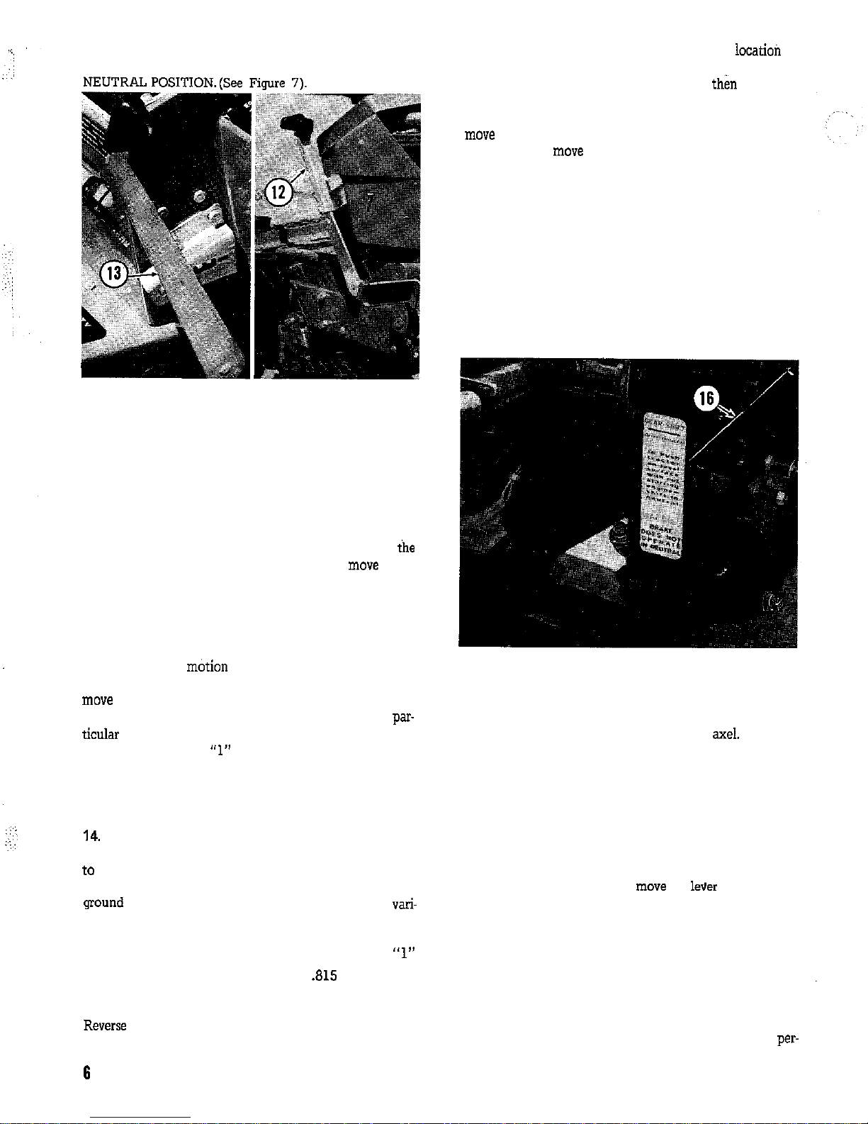
FIGURE 6
12. Hydrostatic Speed Control: (Tractors With Hydrostatic
Transmission): Travel speed of the hydrostatic equipped
tractors is controlled by the control lever at the right of
the instrument panel. Place your hand on top of the control and squeeze the lever so the control can be moved. It
must be in the notched “NEUTRAL” position to start the
engine. The further it is moved forward from this position,
the greater the tractor ground speed forward will be in relation to the engine speed. Moving the lever back from
“NEUTRAL” position will allow the tractor to
in reverse. THE GEAR SHIFT LEVER AT THE REAR OF
THE TRACTOR MUST BE IN THE DRIVE POSITION.
13. Variable Speed Control (Tractors With Variable Speed
Transmission): Tractor ground speed can be changed while
the tractor is in
Control Lever. Place your hand on top of the control and
it to the desired position. Pushing it all the way for-
ward to position 7 will give the greatest speed in any
transmission gear (see item 14). Pulling it all the
way back to position “1” the lowest speed. NEVER ATTEMPT TO MOVE THE VARIABLE SPEED LEVER
UNLESS THE ENGINE IS RUNNING AND THE FOOT
PEDAL IS RELEASED.
Transmission Shift Lever (Tractors with Variable
Speed Transmission): The transmission shift lever is used
There are three forward and one reverse position. The
able speed lever discussed in paragraph 13.
Gear
Variable Control at “7” Variable Control at “1”
First 1.56 MPH .815 MPH
Second
3.65 MPH 2.04
MPH
Third
6.1 MPH 3.36 MPH
3.14 MPH 1.73
MPH
The diagram printed on the panel shows the
of
each position. To shift the transmission into reverse or second, pull the shift lever back toward you,
the way to the right or left into the desired position. To
shift into first or third, push the shift lever forward and
it left or right all the way to the desired position. Do
not attempt to
the shift lever unless the foot pedal
(item 11) is depressed and tractor motion is stopped. The
shift lever must be in the neutral “Start,” position for the
engine to start.
15. Parking Brake Lock: To lock the parking brake, grasp
the lock and pull it upward and back until the handle rests
against the footrest. To release, pull the top portion away
from the footrest and down. The parking brake is located
on the right side of tractors equipped with Hydrostatic
Transmission and on the left side of those with Variable
Speed Transmission.
FIGURE 7
16. Gear Disconnect Lever (Hydrostatic Models Only):
The gear disconnect lever located at the right rear of tractors equipped with the hydrostatic transmission is used to
disengage the transmission from the rear
lever in the NEUTRAL position the tractor may be moved
without engine power. WHEN THE GEAR DISCONNECT
LEVER IS MOVED TO THE NEUTRAL POSITION, THE
BRAKES WILL NOT FUNCTION. NEVER DISENGAGE
DISCONNECT LEVER WHEN TRACTOR IS ON AN INCLINE UNLESS TIRES ARE PROPERLY BLOCKED. Be
sure the hydrostatic control lever is in the NEUTRAL position before attempting to engage or disengage the Gear
Disconnect Lever. To engage,
the lever to the vertical
position until it snaps into the spring clip. Disengage by
pulling the spring lock up and moving the disconnect as far
as possible to the right.
BEFORE STARTING
Though your Simplicity dealer may have performed the
before starting checks listed below, we suggest you
Page 9
with them and also to insure that your tractor is ready to
go the first time you use it.
1. Tire Inflation: The tractor is shipped with all tires in-
flated to 25 PSI. Before operating, reduce pressure in all
tires. The front tires 12 to 15 PSI and rear to 6 to 8 PSI.
2. Engine Oil: Be
the oil in the crankcase is at the
proper level. Remove the dipstick, wipe it clean, and turn
it back in. When removed again, oil should show up to the
full mark. See figure 8.
your
and Stratton
manual and page 15 of this’manual for grade and weight of
oil to use.
FIGURE 8
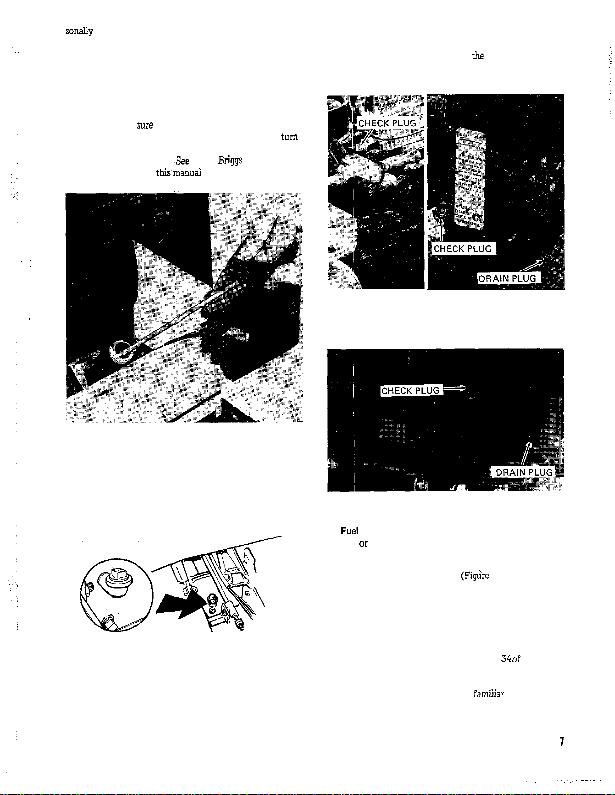
3. Transfer Gear Case Oil: Remove the pipe plug from the
elbow at the rear of the gear case. Oil should be present at
the top of the filler elbow. If it is not, fill with 90 weight
transmission oil.
FIGURE 9
4. Transmission Oil (Hydrostatic Models): Remove the in-
spection plug at the side of the reservoir to check the oil in
the hydrostatic pump. Oil should be level with the bottom
edge of this hole. If it is not see page 17 under Maintenance. Remove the pipe plug from
elbow on the axle
housing. Oil should be level with the top of the elbow. If
it is not see page 17 under Maintenance.
FIGURE 10
(Variable Speed): Remove the fill plug on the right side of
the transmission. Oil should be level with the bottom edge
of this hole. See page 17 of Maintenance.
FIGURE 11
5.
Supply: Fill fuel tank completely with clean, fresh,
leaded or non-leaded “Regular” grade automotive gasoline.
(DO NOT MIX OIL WITH GASOLINE) Store gasoline in
small quantities as prolonged storage produces gum. See
page 9 item 6 of this manual.
6. Battery: Be sure the battery is filled to the proper level
with electrolyte and the vent holes on each cap are open.
See page 18.
7. Lubrication: Lubricate all grease fittings and oil lubri-
cation points shown in figures 32 through 346f the Main-
tenance section of this manual.
8. Attachments: Read and become famiiiar with the AT-
TACHMENTS MANUAL which refers to attachments you
will be using with your tractor. IMPORTANT: If you are
Page 10

:
using
rotary mower with your tractor, the front to rear
height adjustment must be checked.
STARTING THE ENGINE
1. Insure that the power take-off is
by moving
the lever to the rear and down. If your tractor has attachments mounted, be sure the power drives to them are disengaged. (See figure 14).
FIGURE 14
2. Place the transmission shift lever
in neutral. THE ENGINE WILL NOT START UNLESS
THE TRANSMISSION LEVERS ARE IN NEUTRAL.
(See figure 15).
3. Depress the clutch
pedal all the way and hold it
down. (See figure 16).
FIGURE 12
NE
FIGURE 13
FIGURE 15
Page 11

FIGURE 17
5. Pull the choke lever out all the way. (See figure 17).
6. Turn the ignition key clockwise (See figure 17) and hold
until the engine starts, then release. If the engine does not
crank, move the shift lever or hydrostatic control lever forward and back to insure the
switch is making contact. When the engine starts, push the choke in all the way.
If the engine does not start after about half a minute, it
may be flooded. Push the choke in and crank to clear the
engine of excess
lever to fast or slow as needed for the operation. DO NOT
ALLOW THE ENGINE TO RUN IN AN ENCLOSED
BUILDING WHERE CARBON MONOXIDE
AC-
CUMULATE.
STOPPING THE ENGINE
1. Move the speed control lever to the slow position. To
idle for about a minute if the tractor has been
under full load. Stopping a hot engine too
can
damage to engine parts.
2. Turn the ignition key counter clockwise to the vertical
position and remove the key to prevent unauthorized “se
of the tractor.
FIGURE 16
4. Move the engine speed control lever forward about
of the way. (See figure 17).
CONTROLLING TRACTOR GROUND SPEED
Tractor ground speed can be controlled by the
the transmission controls, by adjusting the engine speed
control or by inching (slipping) the clutch. When moving
the tractor from one area to another, be sure all attachments are in the raised “transport” position. When beginning travel set the engine speed at about
to
of
full speed.
(Hydrostatic Drive): The hydrostatic equipped tractor is
designed so forward and reverse movement can be completely controlled without the “se of the clutch. Simply
squeeze the control handle and move it forward to start
the tractor moving ahead. To slow the tractor, move the
control to the rear. As the control is moved further away
from the neutral the tractor ground speed will increase.
The brake pedal may be depressed to stop the tractor at any
time. It is also very handy to use the clutch to slow down
for turns or when moving in tight areas when both, hands
are needed for steering.
(Variable Speed): The variable speed drive has two con-
trols. The three speed gear transmission is used to determine the direction of travel and the forward speed range.
Always depress the clutch-brake pedal and bring the trac-
tor to a complete stop before attempting to shift
See item 11 on page 5.. If the
do not engage easily,
it may be helpful to let the clutch out for an instant and
then depress it again to rotate the gears slightly. The vari-
able speed control can be moved
vary the tractor ground speed in any of the transmission
gears. (See item 13 on page 6
NEVER ATTEMPT TO
MOVE THE VARIABLE SPEED CONTROL UNLESS
THE CLUTCH IS RELEASED AND THE ENGINE
RUNNING.
STOPPING
7. Before applying load to the tractor, allow it to warm up
for about a minute, then move the engine speed control
1. Slowly depress the clutch-brake pedal until the tractor
stops. (Tractors equipped with hydrostatic transmission
can be stopped without depressing the pedal by moving
the hydrostatic control to the “Neutral” position.)
2. Place the tractor in neutral and set the parking brake.
Page 12

3. Disengage the power-take-off clutch and lower any attachments to the ground.
4. If the engine has been working under full load, allow
the engine to idle about a minute before turning the ignition key counterclockwise to the off position.
5. Remove the key to prevent unauthorized use of the
tractor.
TROUBLE SHOOTING
IF THE ENGINE FAILS TO TURN OVER
ELECTRIC
START MODELS, ONLY, check the following:
1. The shift lever must be in Neutral. Move the lever around to be
the safety switch is contacted.
2. The battery cable clamps must be clean and tight.
3. The starter-generator belt must be tight enough to
rotate the engine.
4. The power take-off must be disengaged.
5. The battery may not be charged.
IF THE ENGINE TURNS, BUT WILL NOT START,
check the following:
1. Wiring connection at the switch, regulator, and
2. The engine speed control lever must be about I/3
open and the choke lever pulled out.
IF BELT SLIPPAGE OCCURS, check the following:
1. Belts may be stretched or excessively worn.
2. Pulleys may be greasy or oily.
3. Insufficient belt tension due to a broken or
tension spring.
IF A BELT BREAKS, check the following:
1. Look for sharp edges or rough spots on the pulleys.
2. Pulleys may be misaligned.
3. Belt tension may be too tight.
IF HANDLING IS DIFFICULT, check the following:
1. Controls or drive systems may be out of adjustment,
2. Tires may be under-inflated, or not of equal
sure. Inflate tires to
REAR
PSI FRONT
PSI.
3. Wheels spinning on slopes. Wet
is very slippery
try to work in the late afternoon after it has dried.
Wheel weights may be added to provide additional
traction. See Accessories section of this manual.
IF THE POWER LIFT WILL NOT WORK:
1. Check the ignition switch to be sure it is “ON”.
2. The circuit breaker may have cut out. Wait a few
minutes for it to reset.
3. The spark plug cable must be tightly connected.
4. The fuel tank must have a good
gasoline in it.
5. The power take-off must be in “Neutral”.
10
Page 13

The Landlord and Sovereign tractors have been designed
for easy accessability to areas which need to be reached in
making adjustments and performing maintenance. The underside of the frame has been left open to provide easy ac-
cess to areas requiring lubrication, adjustment or repairs.
The tractor hood is hinged at the front by two spring loaded bolts. It may be easily opened by releasing the two rubber straps which are located one on each side at the rear of
the hood. Pull down and out on the straps to release them.
See figure 18. The tractor seat deck is hinged at the back
by two bolts. To raise the seat deck, reach under the front
of the deck from each side and pull the two locking levers
to the outside. As you hold the locks out, raise the seat
deck. See figure 18.
REAR LOCKS
Starter-Generator Belt: If the starter turns but the engine
does not rotate, the starter-generator belt may need tightening. The belt tension may be adjusted by slightly
loosening the two generator mounting bolts and the two
adjustment arm bolts. A wooden handle or bar approxi-
mately one foot long and
placed between the generator and engine block to tighten
the
in position where the belt is snug, tighten the belt at the
slotted end of the adjustment arm. Actuate the starter to
bolt and apply more tension to the
bolts securely when the adjustment has been completed.
SEAT: The tractor seat may be adjusted from front to rear
in any of four positions. To change position, remove the
two capscrews and two nuts from the underside of the seat
deck
line the seat up with the deck holes in the desired position. When the seat is in the two forward positions, two rubber spacers are used between the seat and
seat deck at the front of the seat. They are not required
when the seat is in the rear position. When the seat is positioned as desired, replace the lockwashers,
and
nuts and tighten securely.
FIGURE 20
Safety Interlock: The safety interlock switch prevents the
starter from actuating if the transmission lever is not in
neutral. It may need adjustment if the starter fails to
check the safety interlock adjustment if movement of the
transmission shift lever or hydrostatic control becomes dif-
ficult. To adjust the safety switch, place the transmission
shift lever in the neutral “START” position. On hydro-
static drive models move the control to the neutral
tion where the back of it just rests against the neutral “Z”
stop on the quadrant. Move the safety switch up or down
as required by rotating the two hexigon nuts on either side
of the bracket. See figure 21 and 22. Position it so the
11
FIGURE 19
Page 14

starter will actuate. If difficulty is experienced in moving
the shift lever through the neutral position, raise the
switch until the shift lever
easily. Place a film of
grease on the end of the safety interlock to reduce friction
and wear.
VARIABLE SAFETY INTERLOCK
FIGURE 21
Power Take-Off Clutch and Belt Stops: The power take-off
clutch can be correctly adjusted only when the attachment
such
a mower or sickle bar is mounted and the drive belt
connected. The clutch adjustment is made by moving the
set collar located
screw on the collar and adjust it so there is about
clearance between the
and the end of the rod guide
when the clutch is engaged. BE SURE, THE SPRING TEN-
SION LEVER AT’TtiE LEFT REAR OF THE TRACTOR
IS PULLED BACK IN THE TIGHTENED POSITION. Set
the clutch only tight enough to drive the attachment without belt slippage. Unnecessary belt tension will cause rapid
wear of the belt and pulleys. See figure 22.
The power take-off belt stop should be adjusted after the
clutch has been adjusted and with the attachment. Loosen
the mounting bolt and adjust the belt stop so it is
from the belt when the clutch is engaged. See figure 22.
Tighten the mounting bolt securely and check the
di-
mension again.
The belt guard located at the top of the power take-off unit should be adjusted so there is
clearance between
the guard and the belt when the power take-off clutch is
engaged. Loosen the mounting bolt and
the belt
guard as required. See figure 22. Tighten the mounting
bolt securely.
12
22
Variable Speed
ALWAYS HAVE’THE
RUNNING
AND THE CLUTCH ENGAGED.‘(RE-
LEASED) WHEN ATTEMPTING TO MOVE THE,VARI-
ABLE SPEED CONTROL LEVER. Adjust the variable
speed drive as follows.
reference numbers correspond
to the numbers on figure
1. With the engine running and the transmi&ion in neutral
place the variable control in the fast (7) position.
2. Remove the spark plug wire and place it at least
inch away from the spark plug.
3. Loosen slightly, the bolt which holds the control arm to
the variable lever.
4. Rotate the engine with the starter and
the variable arm until the belt runs flush with tlie top of the small
pulleys. This may be
easily done by using a bar about
2 to 3 feet long and about
inch in diameter to
the flat variable
See
23.
5. Tighten the bolt loosened in step 3, being careful not to
either the control lever or the variable arm.
6. While rotating the engine with the
the
control lever to the slow (1) position. Loosen the lock nut
at the tumbuckle and alternately adjust the turnbuckle
and rotate the engine. Adjust the turnbuckle so the belt
will ride
below the top of the large pulley when the
engine is rotated.
Page 15

FIGURE 23
7. Replace the spark plug wire and start the engine. Move
the control lever from slow to fast and check your adjustments. Repeat steps 1 through 6 if not correct.
8. Place the variable speed lever in the high (7) position
and adjust the
locknuts so there is
clearance between the
hold the forward one while turning the rear one counterclockwise. Tighten the nuts securely against each other after completing the adjustment. See figure 23.
9. With the variable control in the high (7) position ad-
just the belt guard to obtain a
clearance between
the belt and the guard. See figure 23.
10. Loose” the nut at inside of the clutch idler and adjust
belt stop so the distance between its front edge and the
forward side of the axle is
See figure 23.
tighten the nut and check the adjustments.
Hydrostatic Transmission: If the tractor tends to creep
(move slightly forward or backward) when the hydrostatic
speed control lever is in the Neutral position, the turn-
buckle may need adjusting. See figure 24. To adjust, place
the control lever in the neutral position. THE HYDROSTATIC LOCKOUT AT THE REAR OF THE TRACTOR
MUST BE IN THE “DRIVE” POSITION. Loosen the nuts
at each end of the turnbuckle. Start the engine. If the tractor creeps forward turn the top of the turnbuckle toward
the tractor. If the tractor creeps backward,
the top
of the turnbuckle away from the tractor. When the tum-
buckle is adjusted so the tractor will not creep, tighten the
nuts at each end.
FIGURE 24
The tractor clutch should be adjusted
there is I/8 inch
clearance between the nuts and the rod guide when the
clutch is completely released. See figure
Loosen the
nuts by holding the forward one while turning the rear one
counterclockwise. Retighten the nuts against each other
when the adjustment has been completed.
TIC BRAKE
ADJUSTMENT
FIGURE 25
Brake Adjustment, Foot Pedal: The foot pedal brake ad-
justment is at the right rear of tractors equipped with hy-
drostatic transmissions and at the left rear of those with
the variable speed. See
to loosen the two nuts. Hold the front one and turn the
rear nut counterclockwise to loosen. Turn the forward nut
clockwise to
and counterclockwise, to
loosen. Tighten only enough so the brake will stop the
tractor. Further tightening of the brake may cause the
brake to drag when moving the tractor. When the brake is
adjusted
it works properly, tighten the rear nut up a-
gainst the forward one to lock them in place. Hold the for-
ward one with a wrench so you do not
the adjust-
ment when tightening the nuts together.
13
Page 16

VARIABLE SPEED BkAKE ADJUSTMENT
FIGURE 26
Brake Adjustment, Parking: The parking brake is actuated
and adjusted independentally of the foot brake. It is found
at the rear of the left footrest on tractors with variable
speed transmissions and the right footrest on tractors equipped with hydrostatic transmission. To adjust the parking brake, loosen the nut located behind the footrest. See
figure
the brake lever clockwise to tighten and
FIGURE 27
counterclockwise to loosen the brake. The brake should be
tight enough so it will hold, yet be easily placed in the
“locked” position. Before retightening the locking nut, be
sure the brake lever is positioned so it is in the 1 o’clock
position as viewed from the front on tractors equipped
with variable speed transmission and in the 11 o’clock po-
sition on tractors equipped with hydrostatic transmission.
Page 17

Regular maintenance of your Simplicity tractor will greatly increase its useful life and reduce repair costs. A wide
variety of attachments and accessories permit use of your
tractor throughout the year. BECAUSE YOUR TRACTOR
IS A MULTI-SEASON TOOL, IT IS VERY IMPORTANT
TO SERVICE THE ENGINE FOR THE SEASON IN
WHICH IT WILL BE OPERATED. Be
to change to
winter grade oil before making cold temperature starts.
Fuel refiners change the volatility of gasoline for each season of the year. Using the proper fuel for the season of op
Stratton manual for engine maintenance in addition to the
steps listed here.
EVERY 5 HOURS
Before starting the engine and at least once every five
hours check the oil level in the engine crankcase. Turn the
inspection-fill plug counterclockwise to remove. Maintain
the oil at the FULL line on the engine dipstick. See
figure 28.
FIGURE 28
EVERY 25 HOURS
Every 25 hours or oftener under extremely dusty conditions,
tor and the following maintenance procedures performed:
1. Clean the Cooling System: Continued operation with
a clogged cooling system causes
overheating and
possible engine damage. Remove all grass and chaff from
the engine shrouds and fins, and the flywheel screen at the
lower rear of the tractor.
2. Change Engine Oil: Drain the crankcase when the en-
gine is warm. Remove the oil drain plug found on the left.
See figure 29. After the oil has completely drained
replace the plug and tighten securely. Refill the crankcase
with four pints of a high quality detergent oil classified
MS. It is essential to long engine life that the crankcase oil
remain free of contaminants. Use a clean funnel and clean
the top of the oil can before opening to insure foreign material does not get in the crankcase when you are adding
Winter (Below 400F) Summer (Above 400F)
Use SAE
Use SAE 30
If not Available
If not Available
use SAE
use SAE
30
FIGURE 29
IT IS VERY IMPORTANT TO SERVICE THE ENGINE
ACCORDING TO THE SEASON AND TEMPERATURE
IT WILL BE USED IN.
3. Service the Air Cleaner: Turn the
at the top
center of the air cleaner counterclockwise and remove. Remove the
and foam element. Remove the screen
from inside the foam element. Wash the element in kerosene or liquid detergent and water to remove dirt. Wrap
foam in cloth and squeeze dry. Saturate the foam in engine oil and squeeze to remove excess. Put the screen inside the foam element, being sure the sealing lip is
end of the screen at both the top and bottom. Replace the
element, cover and
and tighten securely.
15
Page 18

FIGURE 31
4. Lubricate Grease Fittings: There are six grease zerks on
the tractor located as follows: two on the front spindles
and one on the steering bearing housing, power take-off,
right
and clutch. Give each zerk about 3 shots of
automotive type grease every 25 hours. See figures 32
through 36.
FIGURE 35
6. Lubricate Pivot Points: Place a few drops of engine oil
on all pivot points to reduce wear and provide for easier
operation. See figures 36 through 38. Be careful not to get
oil on belts or pulleys as it may cause slippage. Place a film
of grease on the steering gear sector. See figure 36.
FIGURE 32
FIGURES 33
36
FIGURE 34
5. Check the Oil Level in the gear box located above the
power take-off. Turn the pipe plug counterclockwise to
The oil should be level with the top of the elbow at
the rear of the gear box. If necessary, add SAE 90 wt.
transmission oil. Reinstall the plug securely. See figure 35.
Page 19

FIGURE 37
FIGURE 38
7. Check the Transmission Oil Level (Variable Speed
Transmission): Remove the plug at the right rear of the
transmission. See figure 39. The oil should be level with
the bottom of this hole. If necessary add SAE 90
mission oil. Replace the plug and tighten securely. It is not
FIGURE 39
normally necessary. but if you wish
drain oil from the
transmission; the drain plug is located at the lower right
side of the transmission.
(Hydrostatic Transmission): Check the oil level of the hy-
drostatic unit with the engine stopped
the plug in the
reservoir. (See figure
to remove. The oil should be level with the bottom of the
threads. If it is not. remove the capscrew and cover from
the top of the reservoir and add Dexron automotive trans-
mission fluid which is available locally from
oil companies. Replace the cover. capscrew and mrpection
plug and tighten
m the
bottom of the reservoir has
be changed only when dirt
gets into the hydraulic oil in the reservoir or the hydrostatic transmission is removed for repair.
essary to change the filter, rern~ve the nut and covet from
the top of the reservoir. Disconnect one of the hoses at the
bottom of the reservoir to drain the oil. Raise the end of
the hose and tie it up so oil will not run out of the
mission. Remove the filter and replace with a new one. Replace the hose and add Dexron Automatic Transmission
Fluid to the reservoir up to the level of the inspection
plug. Replace the
FIGURE 40
Remove the snap out rubber plug from the fan and oil
cooler housing and clean fan and
air or water
under pressure. Replace the plug by pressing it into the
hole.
Check the oil level in the axe1 housing at the elbow located
at the rear of the housing. Remove the pipe plug from the
elbow. Oil should be level with the top of the elbow. If
necessary, add SAE 90 wt. transmission oil. Replace the
plug and tighten securely ( See figure 40).
8. Check the Battery Water Level to insure it is maintained
at the battery ring
inch above the
plates. See figure 41. If water is needed, add distilled water
17
Page 20

just before charging to mix the solution. DO NOT OVER
FILL THE BATTERY.
FIGURE 41
9. Check the Air Pressure on Tires: Front
PSI and
Rear 6-8 PSI.
EVERY 100 HOURS OR ONCE A YEAR
SERVICE
1. Remove the Spark Plug. clean or replace and set the gap
at
DO NOT SAND BLAST PLUGS, AS THE ABRASIVE PARTICLES LEFT ON THE PLUG MAY DAMAGE THE ENGINE. Plugs may be cleaned by scraping or
wire brushing and washing in a solvent.
2. Remove the Battery Cables. ALWAYS REMOVE THE
NEGATIVE “GROUND” CABLE FIRST AND REPLACE
it last. Clean the battery with soap and water to remove all
dirt, oil and corrosion from battery surface. DO NOT ALLOW FOREIGN MATERIAL OR CLEANING SOLUTION
cable clamps with a wire brush. Replace and tighten snugly. After tightening, coat the terminals and clamps liberally
with grease or
Clean and Repack the Front Wheel Bearings. Before at-
tempting to remove the wheel, block or jack the front
of the tractor so the
you are to work on is not
supporting the tractor. Remove the grease cup by pry
the set collar. Remove the set collar, outer bearing, wheel,
and inner bearing. It is best to keep the two bearings separ-
ate, so you can put them back in their original place. Wash
the bearings, shaft and wheel bearing housing with a suit-
able solvent and wipe dry. Inspect the seal at the inner
wheel. Replace it if damaged. Using the palm of your hand
force a good quality wheel bearing grease into the bearings.
‘Place a
where the seal will
turn. Replace the inner bearing and the seal and slide the
wheel on the axel. Replace the outer bearing and the set
collar. Spin the wheel slowly and press in on the set collar
to set the bearings. Be sure the seal on the inside of the
wheel is properly seated. Hold in on the set collar and
tighten the
18
FIGURE 42
Battery Replacement: A dead battery or one too weak to
start the engine may not necessarily mean the battery
needs to be replaced. The voltage regulator or generator
may not be charging it properly. If there is any doubt what
is causing the problem, see your
need to replace the battery, proceed as follows:
1. Disconnect the battery cables, (REMEMBER TO RE.
MOVE THE NEGATIVE “GROUND” CABLE FIRST),
and remove the old battery from the tractor.
2. Wash the battery mounting area and clamps with soap
and water. Remove corrosion from cable ends with a wire
brush. Check the new battery to be sure it is filled with the
special electrolyte to the rings or marks and the vent holes
in the filler caps are open.
3. Carefully place the new battery in the tractor. Fasten
the battery hold down clamp and connect the cables.
CONNECT THE ( + ) POSITIVE CABLE FIRST.
4. After tightening the cable clamps, put a liberal coat of
grease or
To prevent rusting, sand off and paint any parts which become chipped or damaged. Apply a good rust preventative
to all bare metal parts. Keep all
and guards tight-
ened securely.
OFF SEASON STORAGE
When the tractor is to be stored without use for a period
of one month or longer, the
precautions should
Page 21

1. Drain the
tank completely by cunning the tractor
until it stops. This may be easily done by removing the gas
line at the carburetor, and draining the tank through this
hose. If you desire, fuel may be stored in the tank or a
used. This
prevents formation
gum and varnish for up to one year,
providing easier starting and a clean fuel system.
2. Drain and refill the crankcase when the engine is warm.
See “Maintenance”.
3. Remove spark plug,
one ounce of low-30 oil into
cylinder through plug hole. Crank engine a few times to
distribute oil and reinstall the plug.
4. Clean dirt and chaff from cylinder head fins and engine
housing.
5. Grease all zerks and apply oil to all points shown in
“Maintenance”.
6.. Block the machine up off the wheels to relieve weight
and keep tires off a damp floor. Protect the tires from prolonged exposure to direct sunlight.
7. Store the machine in a dry place indoors.
STARTING AFTER STORAGE
1. Remove the spark plug and wipe dry. Crank the engine
a few times to blow the excess oil out of the plug hole.
install the plug.
2. Fill the fuel tank with fresh
a fuel stabilizer has been used.)
3. Service the air cleaner. See “Maintenance”.
4. Check the crankcase oil level and replenish if necessary.
See “Maintenance”.
5. Start the engine outdoors or in a well ventilated area.
DO NOT run the engine at high speed immediately after
starting.
6. Inflate the front
to 12.15 PSI and rear to
PSI.
REPLACEMENT PARTS
Replacement parts for your Simplicity equipment should
be purchased from your Simplicity dealer. Be prepared to
give him the tractor name, model and the ID number
found on the plate pictured below.
USE ONLY SIMPLICITY BELTS AND BLADES.
Page 22

ENGINE SPECIFICATIONS SOVEREIGN LANDLORD
MAKE
I
& Stratton
MODEL NO.
320421 243431
NUMBER OF CYLINDERS
One (Cast Iron)
CRANK SHAFT PLANE
Horizontal
HORSEPOWER (AT 3600 RPM)
14
10
PISTON DISPLACEMENT 32.4 Cu. In.
BORE
STROKE 3.114” 3.114”
CYLINDER MATERIAL Cast Iron
EXHAUST VALVE AND SEAT
VALVE ROTATORS
I
SYNCHRO BALANCED
Horizontally, 60% Vertiaally) Yes
Patented High Voltage Magneto
GOVERNOR TYPE
Adjustable Mechanical Fully Enclosed and Lubricated
1000-3600 1000.3600
LUBRICATION Splash, Capacity 4 Pints
STARTING (Key Controlled with Solenoid) Electric Starter Generator
VOLTAGE REGULATOR
3 Unit Type
BATTERY
PROTECTION (Electrical)
AIR CLEANER
MUFFLER
FUEL CAPACITY (Gage isstandard Equipment)
40 Ampere Hour, 12 Volt
20 Ampere Circuit Breaker and Warning Light
Reusable Oil Foam Type
Large, Quieter Enclosed
3 Gallons (Regular Grade Gasoline)
Page 23

HYDROSTATIC TRANSMISSION
TYPE
LUBRICATION AND WORKING FLUID
TEMPERATURE PROTECTION
IDENTIFICATION
DISCONNECT (PUSHING)
SPEEDS (STEPLESS HOLDS POSITION)
SOFT RIDE VALVE
PROTECTION
GEAR REDUCTION UNIT (HOUSING)
GEARS and BEARINGS
LUBRICATION
VARIABLE SPEED TRANSMISSION
Piston to Piston
Type A Automatic Transmission
Oil Cooler with Fan and Cold Weather By-Pass Valve
Pattern Control
Sliding Gear
V-Belt Idler Drive
O-7 MPH Forward, O-4 MPH Reverse
Fast Acting (No Spring Change Required for Tilling)
High Pressure Relief Valve: Filter
Cast Iron Housing ZF
Hardened Spur Gears, Rolling Contact Bearings
SAE 90 Gear Oil
Quarts
MAKE
TYPE
SPEED RANGE (7 STEPS EACH GEAR)
1st GEAR
2nd GEAR
3rd GEAR
REVERSE
CONSTRUCTION -HOUSING
GEARS
BEARINGS
LUBRICATION
Simplicity
Synchronized Variable Speed Sheaves and 3 Speed
Spur Gear Transmission
2.04 to 3.65 MPH
3.36 to 6.1 MPH
1.73 to 3.14 MPH
Cast Iron
Hardened Spur Gears
Rolling Contact
SAE 90, Capacity l-314 Quarts
21
Page 24

BEVEL GEAR HOUSING
(Hydrostatic and Variable)
MAKE
Simplicity
HOUSING MATERIAL
I
Cast Iron
Bevel Type, Hardened Steel
BEARINGS
Rolling Contact
LUBRICATION
SAE 90, Capacity 1 Quart
DIFFERENTIAL (Hydrostatic and Variable)
I
Simplicity
HOUSING MATERIAL
Drawn Steel
GEARS
LIMITED SLIP
Spur Type. Hardened Steel
8 Springs and Hardened Washers Automatically Transfer
Maximum Driving Force From Slipping Wheel Which is
Possible Without Scuffing Lawns On Turns.
CLUTCH/BRAKE (Single Pedal)
PARKING BRAKE
Clutch
V-Belt Idler. Brake Is Band Type. Cam Controlled
For Controlled Uphill Starts- Operat&lndependently
Of Foot Brake.
FRAME
I
Welded Deep Drawn Steel, Open Construction
FRONT AXLE PIVOT
I
Large Area Belt With “Wishbone” Support For Added Stability
STEERING
I
Bevel Gear Type, Ratio 4.66
1 .O
SEAT
I
Large High Back With Drain Slot. Black
Over
Thick Moulded Foam Rubber Cushion.
DIMENSIONS:’
OVERALL LENGTH (LessAttachments)
OVERALL WIDTH (Less Attachmenrs)
OVERALL HEIGHT TO TOP OF STEERING WHEEL
OVERALL HEIGHTTO TOP OF HOOD WHEEL
OVERALL HEIGHT TO TOP OF HOOD CLOSED
WHEEL BASE
SOVEREIGN
67”
35”
35”
LANDLORD
67”
35”
35”
48”
Page 25

GROUND CLEARANCE, FRONT AXLE
AT DIFFERENTIAL
CENTER OF FRAME
ATTACHMENT MOUNTING (Front and Center)
REAR
ATTACHMENT LIFT MANUAL (Standard)
POWER (Optional)
READ FRONT (Inside Tires)
TREAD REAR (Inside Tires)
TURNING RADIUS
TIRES,
TYPE AND INFLATION PRESSURE
TREAD
TIRES, REAR, Size
NET WEIGHT
SIDE HILL AND UPHILL OPERATION
30”
26”
I
8
Pneumatic, 6-8 psi Rear,
psi Front
Turf
12
20% Slope without Wheel Weights
40% Slope with Wheel Weights
9”
7”
Attachments Mount To And Tilt With Front Axle.
with 2 PinsAnd Spring Clips (No Tools Required)
Bar And Lower And Upper Pivoting Horizontal Mount-
ing
Standard. Movable Mast To Complete 3 Point Hitch Is
Lift Lever With Notched Sector Includes Float Position Cam
Electric Powered, Highly Efficient Recirculating Ball Screw,
Easily Installed. Stops Precisely (Includes Brake) And Holds
Position.
Page 26

MFG.
NO.
574
NO.
673
MFG.
NO.
504
MFG.
NO.
686
MFG.
NO.
685
MFG.
NO.
689
MFG.
NO.
466
MFG. NO. 280
MFG.
NO.
617
MFG.
NO.
536
MFG.
NO.
449
NO.
668
MFG.
NO.
182
MFG.
NO.
045
MFG.
NO.
658
MFG.
NO.
584
MFG.
NO.
690
MFG.
NO.
523
MFG.
NO.
315
MFG.
NO. 181
MFG.
NO.
635
MFG.
NO.
636
MFG.
NO.
632
24
SNOW TIRE AND WHEEL SET
SNOW CAB
540 RPM REAR PTO
SPLINE)
BALL HITCH FRONT
BALL HITCH REAR
FRONT LIGHT KIT (STANDARD EQUIPMENT ON SOVEREIGN)
REAR LIGHT KIT (REQUIRES 689 FOR LANDLORD)
HUB CAPS, SET OF 4
HUB CAPS, FRONT PAIR ONLY
WEIGHT, WHEEL, REAR
WEIGHT, WHEEL, FRONT
WEIGHT, FRONT
WEIGHT, REAR
WEIGHT, AUXILIARY (FITS ON 182)
POWER LIFT KIT
DUAL WHEEL SPACER (REQUIRES NO. 574)
REAR LIFT KIT
CHAINS, PAIR FOR THE SIZE
10.50 x 12)(SOVEREIGN)
CHAINS, PAIR FOR TIRE SIZE (23
8.50
12)(LANDLORD)
CHAINS, PAIR FOR TIRE SIZE (6
IS)(SNOW TIRES)
STORAGE COVER (TRACTOR AND MOWER OR GRADER BLADE)
STORAGE COVER (TRACTOR, MOWER &TILLER OR SNOW THROWER OR
DOZER BLADE.
Page 27

Page 28

 Loading...