

Page 1
Assisting the automation
industry since 1986
User manual
DATA RECORDER
SRD-99
•
Firmware: v.3.34 b1 or higher
•
Loggy Soft: v.1.9.0 or higher
•
S-Toolkit: v.2.0.23 or higher
Read the user's manual carefully before starting to use the unit or software.
Producer reserves the right to implement changes without prior notice.
2016.10.19 SRD-99_INSSXEN_v.3.06.005
Page 2

User manual - DATA RECORDER SRD-99 and cooperating software
CONTENTS
I. USER MANUAL FOR DATA RECORDER................................................................4
1. BASIC REQUIREMENTS AND USER SAFETY........................................................................................4
2. GENERAL CHARACTERISTICS................................................................................................................5
3. TECHNICAL DATA......................................................................................................................................7
4. DEVICE INSTALLATION..........................................................................................................................10
4.1. UNPACKING....................................................................................................................................10
4.2. ASSEMBLY......................................................................................................................................10
4.3. CONNECTION METHOD.................................................................................................................13
4.3.1.Connections of current type inputs ( I version ).......................................................................16
4.3.2.Connections of temperature type inputs ( RTD version ).......................................................17
4.4. MAINTENANCE................................................................................................................................18
5. FRONT PANEL DESCRIPTION................................................................................................................19
6. PRINCIPLE OF OPERATION...................................................................................................................20
6.1. MEASUREMENT MODE..................................................................................................................20
6.1.1.Measurement ranges definition of current inputs ( I version ).................................................20
6.1.2.Measurement ranges definition of voltage inputs ( U version )...............................................21
6.1.3.Measurement ranges definition of RTD inputs ( RTD version )..............................................21
6.1.4.Measurement ranges definition of TC inputs ( TC version )....................................................22
6.1.5.Recording momentary and averaged data...............................................................................22
6.2. MODES OF RESULT PRESENTATION..........................................................................................24
6.2.1. "Single channel" mode............................................................................................................25
6.2.2."Measurements list" mode.......................................................................................................26
6.2.3.”Graph” mode...........................................................................................................................29
6.2.4.”Channels List” mode...............................................................................................................31
6.3. PRINCIPLE OF OUTPUTS OPERATION........................................................................................33
6.3.1.Alarms......................................................................................................................................33
6.3.2.Outputs control.........................................................................................................................34
6.3.3.Example of output control........................................................................................................36
7. DEVICE PROGRAMMING.........................................................................................................................37
7.1. PARAMETERS EDITION.................................................................................................................39
7.1.1.Numeric and switching parameters ("LIST" - type)..................................................................39
7.1.2. Text parameters......................................................................................................................40
7.1.3.“SLIDER” - type parameters.....................................................................................................41
7.2. DESCRIPTION OF RESULTS PRESENTATION MODES MENU.................................................42
7.2.1."Measurements list options" menu...........................................................................................42
7.2.2.”Graph options” menu..............................................................................................................43
7.2.3.”Channels list options” menu....................................................................................................43
7.3. RESULTS PRESENTATION MODES MENU STRUCTURE..........................................................44
7.4. MAIN MENU DESCRIPTION...........................................................................................................45
7.4.1.”Device information” menu.......................................................................................................45
7.4.2.”Display options” menu............................................................................................................45
7.4.3.”Logging setup” menu..............................................................................................................46
7.4.4.“Temperature unit” parameter (RTD version)..........................................................................48
7.4.5.”Input settings” menu (common parameters)...........................................................................49
7.4.6.”Input settings” menu ( I version )............................................................................................50
7.4.7.”Input settings” menu ( U version )...........................................................................................51
7.4.8.”Input settings” menu ( RTD version )......................................................................................53
7.4.9.”Outputs settings” menu...........................................................................................................54
7.4.10.”Date & time settings” menu..................................................................................................55
7.4.11.”RS485 port settings” menu...................................................................................................56
7.4.12.”Access setup” menu.............................................................................................................57
7.4.13.”USB options” menu...............................................................................................................57
7.4.14.”Language” parameter............................................................................................................58
2
Page 3

User manual - DATA RECORDER SRD-99 and cooperating software
7.5. MAIN MENU STRUCTURE..............................................................................................................59
8. DOWNLOADING DATA FROM DATA LOGGER.....................................................................................61
8.1. MODBUS (RS485) DATA DOWNLOAD..........................................................................................61
8.2. USB FLASH DRIVE (PENDRIVE) DATA DOWNLOAD..................................................................61
9. THE MODBUS PROTOCOL HANDLING.................................................................................................64
9.1. LIST OF REGISTERS......................................................................................................................64
9.2. TRANSMISSION ERRORS HANDLING..........................................................................................69
9.3. EXAMPLES OF QUERY/ANSWER FRAMES.................................................................................70
10. USER'S SETTINGS LIST........................................................................................................................73
II. USER MANUAL FOR “LOGGY SOFT”.................................................................80
1. GENERAL CHARACTERISTICS..............................................................................................................80
2. INSTALLATION AND STARTUP..............................................................................................................80
3. USING THE PROGRAM............................................................................................................................83
3.1. „CURRENT MEASUREMENT” MENU.............................................................................................84
3.2. „REPORTS” MENU..........................................................................................................................84
3.2.1.„Table” tab................................................................................................................................85
3.2.2.„Graph” tab...............................................................................................................................87
3.3. „CONFIGURATION” MENU.............................................................................................................92
3.3.1.„Devices” tab............................................................................................................................93
3.3.2.„Groups” tab - group operations...............................................................................................97
3.3.3.„Settings” tab............................................................................................................................99
3.4. LIST OF ERRORS AND FAULT DIAGNOSTICS .........................................................................101
III. USER MANUAL FOR “S-TOOLKIT”..................................................................102
1. GENERAL CHARACTERISTICS............................................................................................................102
2. INSTALLATION AND STARTUP............................................................................................................102
3. USING PROGRAM..................................................................................................................................103
3.1. “INPUTS SETTINGS” TAB.............................................................................................................104
3.2. “OUTPUTS SETTINGS” TAB.........................................................................................................105
3.3. “LOGGING SETUP” TAB...............................................................................................................105
3.4. “INTERFACE OPTIONS” TAB......................................................................................................106
3.5. “DEVICE INFORMATION” TAB.....................................................................................................108
3.6. CONFIGURATION MODES...........................................................................................................109
3.6.1.Individual configuration of channels.......................................................................................109
3.6.2.Configuring selected channels...............................................................................................109
3.6.3.Configuring all channels.........................................................................................................109
3.7. UPDATING DEVICE FIRMWARE..................................................................................................110
3
Page 4
User manual - DATA RECORDER SRD-99 and cooperating software
Explanation of symbols used in the manual:
- This symbol denotes especially important guidelines concerning the installation and
operation of the device. Not complying with the guidelines denoted by this symbol
may cause an accident, damage or equipment destruction.
IF THE DEVICE IS NOT USED ACCORDING TO THE MANUAL THE USER IS
RESPONSIBLE FOR POSSIBLE DAMAGES.
- This symbol denotes especially important characteristics of the unit.
Read any information regarding this symbol carefully
I. USER MANUAL FOR DATA RECORDER
1. BASIC REQUIREMENTS AND USER SAFETY
-
The manufacturer is not responsible for any damages caused by
inappropriate installation, not maintaining the proper environmental
conditions and using the unit contrary to its assignment.
- Installation should be conducted by qualified personnel . During installation all
available safety requirements should be considered. The fitter is responsible for
executing the installation according to this manual, local safety and EMC
regulations.
- The unit must be properly set-up, according to the application. Incorrect
configuration can cause defective operation, which can lead to unit damage or
an accident.
- If the device is equipped with PE conntector, it should be connected to PE wire.
-
If in the case of a unit malfunction there is a risk of a serious threat to the
safety of people or property additional, independent systems and
solutions to prevent such a threat must be used.
-
The unit uses dangerous voltage that can cause a lethal accident. The unit
must be switched off and disconnected from the power supply prior to
starting installation of troubleshooting (in the case of malfunction).
- Neighbouring and connected equipment must meet the appropriate standards
and regulations concerning safety and be equipped with adequate overvoltage
and interference filters.
-
Do not attempt to disassemble, repair or modify the unit yourself. The unit
has no user serviceable parts. Defective units must be disconnected and
submitted for repairs at an authorized service centre.
4
i
!
!
Page 5

User manual - DATA RECORDER SRD-99 and cooperating software
2. GENERAL CHARACTERISTICS
• Multifunctional
Device is designed for recording, displaying current or averaged values and
presentation of technological parameter trends in graphic form.
• Large data storage capacity
The registered measurement results are recorded in the unit's memory. The
capacity of installed memory allows to store:
–
over 500 000 measurements (2MB) for units equipped with RS-485 interface
–
over 2 000 000 measurements (8MB) for units equipped with RS-485 interface
and USB Host port.
• Configurable measurement and control input
The unit has up to 8 channels (depending on version) of measurement signals and
one digital voltage input with programmable functions, e.g. control of the recording
process. Each signal can be freely configured and described. Depending on device
version all measured parameters must be available as current type signals
(0-20 mA or 4-20 mA standards) or resistance (Pt100, Pt500 or Pt1000 standards).
The internal analogue-digital converter has a 12 or 16 bit resolution (depending on
input type), which provides high measurement resolution results. Additionally,
individual alphanumeric description (text) of each of the recorded channels is
possible.
• Fast serial interface
The data logger is fitted with a galvanic isolation RS-485 interface, programmed
with ModBus RTU transmission protocol. This enables the connection of a number
of data recorders into the network, remote collecting of data from each unit and also
remote configuration. The application of the RS-485 interface instead of RS-232 is
due to the possibility of achieving high transmission speeds using transmission lines
of larger length than is possible with the RS-232 interface.
• Built-in USB Host interface (optional)
Optionally the device can be equipped with built-in USB Host interface, allowing for
data transfer to popular USB Flash Drives (PenDrives). This method allows for
significant simplification of unit application: it is no longer necessary to connect PC
and data logger via RS-485 interface.
Significant acceleration of data transfer is an additional advantage: data download
can be 10 times faster than using RS-485 interface.
WARNING!
Device should work properly with any standard Flash Drives, but
manufacturer can not guarantee proper cooperation with non-standard devices, or
with devices developed after data logger release.
5
Page 6

User manual - DATA RECORDER SRD-99 and cooperating software
• Wide range of power supply voltage and external sensor power supply
The built-in pulse power supply allows power to be supplied to the unit with
85...
230
...260V AC/DC voltage or 16...24...35 AC, 19...24...50 DC voltage
(depending on version). Data logger (version with current inputs only) is equipped
with voltage output for powering the sensor and converters: 24V DC ±5% / max.
200mA.
• Legible graphic display
The 128 x 64 points display with a backlight mounted on front of the unit is a big
advantage of the data recorder. It allows the display of trend graphs for each
channel separately. Different operation modes provide the possibility of selecting
and adjusting the method of data presentation depending on the user's
requirements. Data recording intervals are selected by the user from the menu
level. Additionally, it is possible to set the display to show one current value
measured for a selected channel.
• Easy configuration
There are 6 keys on the front of the data recorder that enable the configuration of
the unit. The menu assisted with full text descriptions makes the unit configuration
process quite easy. However, due to a significant number of configured parameters
it is advised to use the attached configuration software for PCs.
6
Page 7

User manual - DATA RECORDER SRD-99 and cooperating software
3. TECHNICAL DATA
Power supply voltage
(depending on version)
External Fuse (required)
Power consumption
85...
230
...260V AC/DC; 50 ÷ 60 Hz (separated)
or 19...24...50V DC and 16V...24...35V AC (separated)
T - type, max. 2 A
typically 7 VA; max. 12 VA
Measurement inputs
(depending on version)
I version:
RTD version:
up to 8 inputs 0-20 mA or 4-20 mA, common ground
up to 8 inputs Pt100, Pt500 or Pt1000 type with
automatic connection recognition (2 or 3-wires)
Digital input 1 input 24V DC, galvanic isolation
power consumption: 7,5 mA / 24V,
isolation: 1min @ 500V DC.
Digital outputs 2 electronic relays, NO type, 24V AC / 35V DC /
max. 200 mA, overload protection
Recording cycle 1 sec./ 2 sec. / 5 sec. / 10 sec. / 15 sec. / 20 sec. /
30 sec. /1 min. / 2 min. / 5 min. / 10 min. / 15 min. /
20 min. / 30 min. / 60 min.
Communication interface
Baud rate
RS-485, 8N1 / Modbus RTU, galvanic isolated:
1min @ 500V DC.
1200 bit/s ÷ 115200 bit/s
USB Host interface (optional) Cooperation with standard Flash Disks (USB 2.0)
Display
Data memory
LCD graphic display, 128 x 64 points, with backlight
2MB - version without USB Host
8MB - version with USB Host interface
Protection level
version without USB interface IP 65 (from front, after using waterproof cover)
IP 40 (from front)
IP 20 (housing and connection clips)
version with USB interface IP 54 (from front, after using waterproof cover)
IP 20 (housing and connection clips)
Housing type
Housing material
Housing dimensions
Mounting hole
Assembly depth
Panel thickness
panel
NORYL - GFN2S E1
96 x 96 x 100 mm
90,5 x 90,5 mm
102 mm
max. 5 mm
Operating temperature
Storage temperature
Humidity
Altitude
0°C to +50°C
-10°C to +70°C
5 to 90% no condensation
up to 2000 meters above sea level
Screws tightening max. torque 0,5 Nm
Max. connection leads diameter 2,5 mm
2
7
Page 8

User manual - DATA RECORDER SRD-99 and cooperating software
Safety requirements according to: PN-EN 61010-1
installation category: II
pollution degree: 2
voltage in relation to ground: 300V AC
insulation resistance: >20MΩ
insulation strength between power supply and
input/output terminal: 1min. @ 2300V (see
Fig. 3.1
)
EMC PN-EN 61326-1
Device described in this manual is available in two versions differed by
measurement inputs type. This manual contain following short descriptions:
I version - means device with current type inputs (0..20mA / 4..20mA)
RTD version - means device with RTD-type inputs (Pt100 / Pt500 / Pt1000)
Parameters of current type inputs (
I version
)
Input type 0-20 mA or 4-20 mA, common ground
Measurement range ± 9999 plus decimal point
Current measurement accuracy ± 0.1% @ 25°C; ± one digit (for 0-20 mA range)
Temperature stability 50 ppm / °C
Sampling rate 8 sps
Accepted prolonged input overload 20%
Measurement input resistance
100 Ω
Sensor power supply output 24V DC ± 5% / max. 50 mA,
Not insulated from measurement inputs
Parameters of RTD type inputs (
RTD version
)
Input type Pt100, Pt500 or Pt1000 type with automatic
connection recognition (2 or 3-wires)
Measurement range -100°C ÷ +600°C
-148°F ÷ +999,9°F
Measurement accuracy ± 0.15% @ 25°C; ± one digit
Temperature stability 100 ppm / °C
Sampling rate 1 sample per 2.5 sec
Measurement wires resistance
max. 20 Ω (every wire)
Cables connected to RTD inputs can not be longer than 30 meters and must be laid
completely in building.
Software (Windows environment)
•
S-Toolkit
, PC software for data logger easy configuring,
•
Loggy Soft
, PC software for moving, reporting, archiving and displaying recorded data.
8
i
!
Page 9

User manual - DATA RECORDER SRD-99 and cooperating software
This is a class A unit. In a residential or a similar area it can cause radio
frequency interference. In such cases the user can be requested to use
appropriate preventive measures.
Carefully check that the isolation used with the unit (
Fig. 3.1
) meets the
expectations and if necessary use appropriate measures of overvoltage protection.
Additionally, insure the appropriate air and surface insulation gaps when installing
(
Tab. 3.1
).
Range of operating voltage Air gap [mm] Surface gap [mm]
Up to 50V RMS or DC 0,2 1,2
Up to 100V RMS or DC 0,2 1,4
Up to 150V RMS or DC 0,5 1,6
Up to 300V RMS or DC 1,5 3,0
Tab. 3.1. Minimal insulation gaps according to EN 61010-1
Fig. 3.1. Schematic diagram showing the insulation between individual circuits of the unit.
9
!
!
Internal circuits
relay 2
relay 1
External sensor
supply output
Measurement inputs
RS 485
interface
Reinforced insulation 1min @ 2300V AC
Supplementary insulation 1min @ 1350V AC
Basic insulation 1min @ 500V AC
No insulation
Relay circuits
Power
supply
Page 10
User manual - DATA RECORDER SRD-99 and cooperating software
4. DEVICE INSTALLATION
The unit has been designed and manufactured in a way assuring a high level of user
safety and resistance to interference occurring in a typical industrial environment. In order to
take full advantage of these characteristics installation of the unit must be conducted correctly
and according to the local regulations.
- Read the basic safety requirements on page 4 prior to starting the installation.
- Ensure that the power supply network voltage corresponds to the nominal
voltage stated on the unit’s identification label.
- The load must correspond to the requirements listed in the technical data.
- All installation works must be conducted with a disconnected power supply.
- Protecting the power supply connections against unauthorized persons must be
taken into consideration.
4.1. UNPACKING
After removing the unit from the protective packaging, check for transportation damage.
Any transportation damage must be immediately reported to the carrier. Also, write down the
unit serial number located on the housing and report the damage to the manufacturer.
4.2. ASSEMBLY
- The unit is designed for mounting inside housings (control panel, switchboard)
inssuring appropriate protection against surges and interference. Metal housings
must be connected to ground in a way that complies with the governing
regulations.
- Disconnect the power supply prior to starting assembly.
- Check the connections are wired correctly prior to switching the unit on.
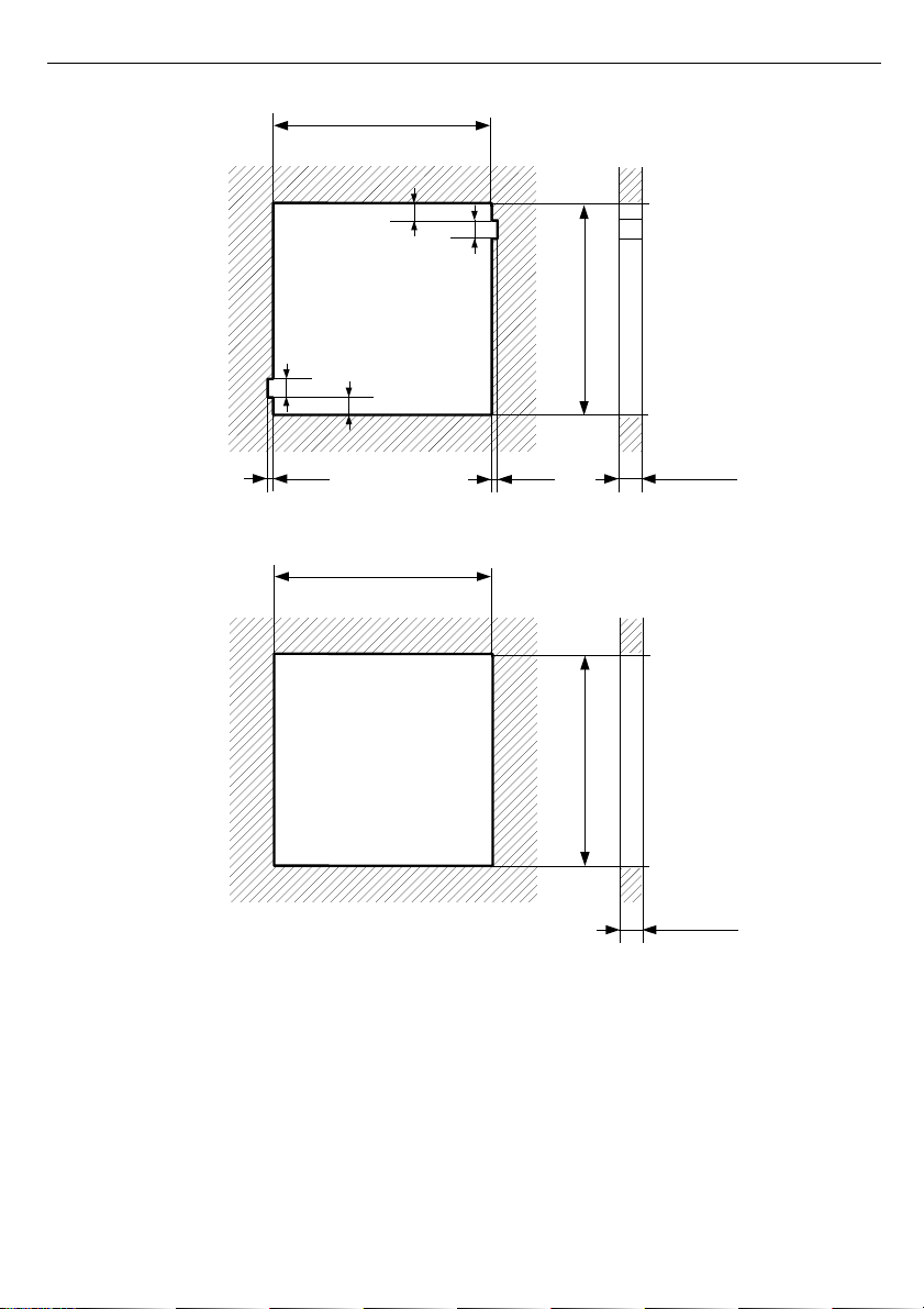
In order to install the unit, a 90,5 x 90,5 mm mounting hole (
Fig. 4.1
) must be
prepared. The thickness of the material of which the panel is made must not exceed
5mm. When preparing the mounting hole take the grooves for catches located on
both sides of the housing into consideration (
Fig. 4.1
). Place the unit in the
mounting hole inserting it from the front side of the panel, and then fix it using the
brackets (
Fig. 4.3
). The minimum distances between the center points of multiple
units - due to the thermal and mechanical conditions of operation - are 115 mm x
115 mm (
Fig. 4.5
).
10
!
!
Page 11
User manual - DATA RECORDER SRD-99 and cooperating software
Fig. 4.1. Recommended mounting hole dimensions
Fig. 4.2. Allowable mounting hole dimensions
11
92 mm
max. 5 mm
90,5 mm
90,5 mm
13 mm
8 mm
8 mm
13 mm
1 mm
max. 5 mm
90,5 mm
1 mm
Page 12
User manual - DATA RECORDER SRD-99 and cooperating software
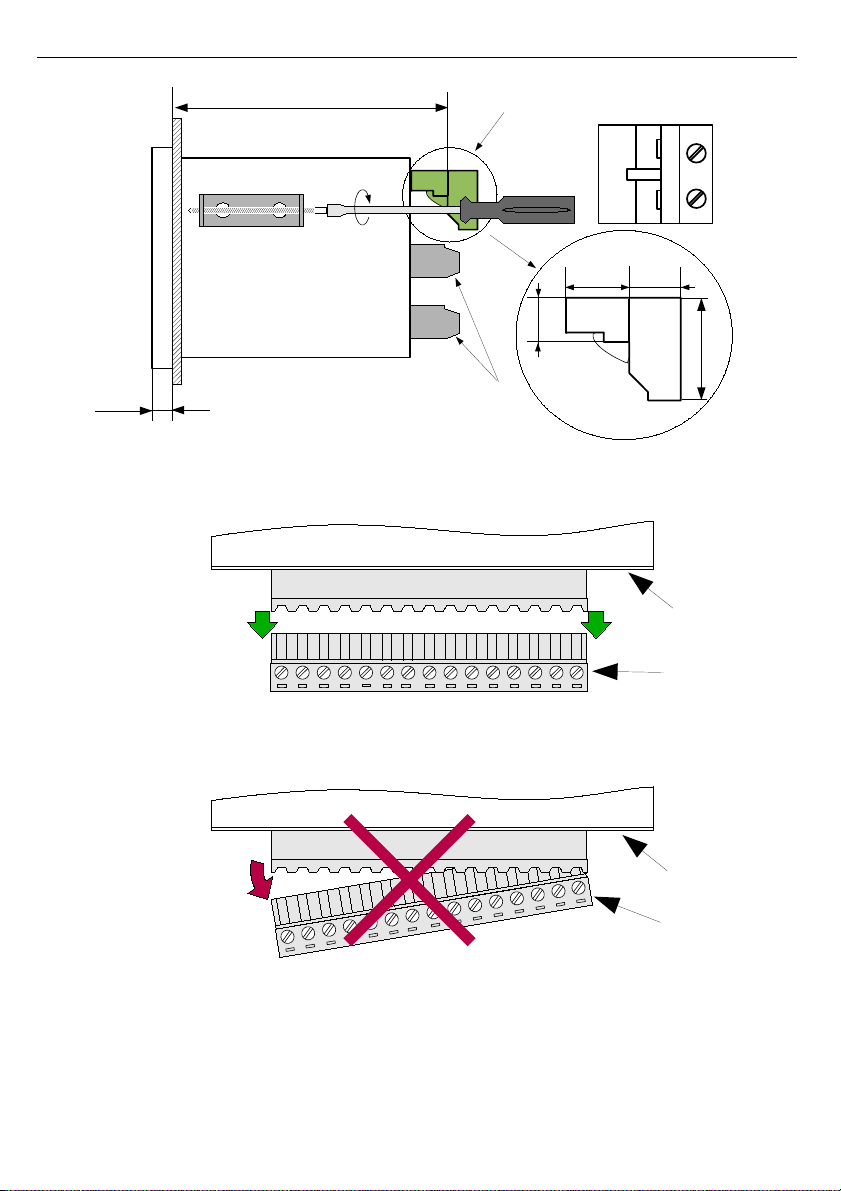
Fig. 4.3. Installing of brackets, and dimensions of connectors.
Fig. 4.4. Connectors removing method
12
back side
of device
connector
GOOD
back side
of device
connector
WRONG
92 mm
8 mm
12 mm
10 mm
8,5 mm
16 mm
removable terminals
NOTE:
I version - removable terminals
RTD version - immovable terminals
Page 13

User manual - DATA RECORDER SRD-99 and cooperating software
Fig. 4.5. Minimum distances when assembly of a number of units
4.3. CONNECTION METHOD
Caution
- Installation should be conducted by qualified personnel. During installation all
available safety requirements should be considered. The fitter is responsible for
executing the installation according to this manual, local safety and EMC
regulations.
- The unit is not equipped with an internal fuse or power supply circuit breaker.
Because of this an external time-delay cut-out fuse with a small nominal current
value must be used (recommended bipolar, max. 2A) and a power supply circuitbreaker located near the unit. In the case of using a monopolar fuse it must be
mounted on the phase cable (L).
- The power supply network cable diameter must be selected in such a way that in
the case of a short circuit of the cable from the side of the unit the cable shall be
protected against destruction with an electrical installation fuse.
- Wiring must meet appropriate standards and local regulations and laws.
- In order to secure against accidental short circuit the connection cables must be
terminated with appropriate insulated cable tips.
- Tighten the clamping screws. The recommended tightening torque is 0.5 Nm.
Loose screws can cause fire or defective operation. Over tightening can lead to
damaging the connections inside the units and breaking the thread.
- The separable clamps should be inserted into appropriate connectors in the unit,
even if they are not used for any connections.
- Unused terminals (marked as n.c.) must not be used for connecting any
connecting cables (e.g. as bridges), because this can cause damage to the
equipment or electric shock.
13
!
115 mm
115 mm
Page 14

User manual - DATA RECORDER SRD-99 and cooperating software
- If the unit is equipped with housing, covers and sealing to, protecting against
water intrusion, pay special attention to their correct tightening or clamping. In the
case of any doubt consider using additional preventive measures (covers, roofing,
seals, etc.). Carelessly executed assembly can increase the risk of electric shock.
- After the installation is completed do not touch the unit’s connections when it is
switched on, because it carries the risk of electrical shock.
Due to possible significant interference in industrial installations appropriate measures
assuring correct operation of the unit must be applied. To avoid the unit of improper
indications keep recommendations listed below.
-
Avoid running signal cables and transmission cables together with power supply cables
and cables controlling inductive loads (e.g. contactors). Such cables should cross at a
right angle.
-
Contactor coils and inductive loads should be equipped with interference protection
systems, e.g. RC-type.
-
Use of screened signal cables is recommended. Signal cable screens should be
connected to the earthing only at one of the ends of the screened cable.
-
In the case of magnetically induced interference the use of twisted pair of signal cables is
recommended. Twisted pair (best if shielded) must be used with RS-485 serial
transmission connections.
-
In the case of measurement or control signals are longer than 30m or go outside of the
building then additional safety circuits are required.
-
In the case of interference from the power supply side the use of appropriate interference
filters is recommended. Bear in mind that the connection between the filter and the unit
should be as short as possible and the metal housing of the filter must be connected to
the earth with the largest possible surface. The cables connected to the filter output must
not be run with cables with interference (e.g. circuits controlling relays or contactors).
Connections of power supply voltage and measurement signals are executed using the
screw connections on the back of the unit’s housing.
Fig. 4.6. Method of cable insulation replacing and cable terminals dimensions
All connections must be made while power supply is disconnected !
14
!
!
6-7 mm
max. 2 mm
Page 15
User manual - DATA RECORDER SRD-99 and cooperating software
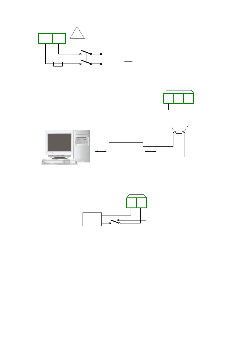
Depending on version:
85...230...260V AC/DC or
19...24...50V DC; 16...24...35V AC
Fig. 4.7. Connection of power supply
Fig. 4.8. Connection of RS-485 transmission signals
Fig. 4.9. Connection of digital input (depending on data recorder configuration)
15
9 10
24 V DC
recording enable
external switch
external
supply
digital
input
DIN- DIN+
!
FUSE
1 2
L N
N
L
12 13
RS-485
DATA-
GND-RS
14
DATA+
RS-232/485
interface
-
+
Page 16
User manual - DATA RECORDER SRD-99 and cooperating software
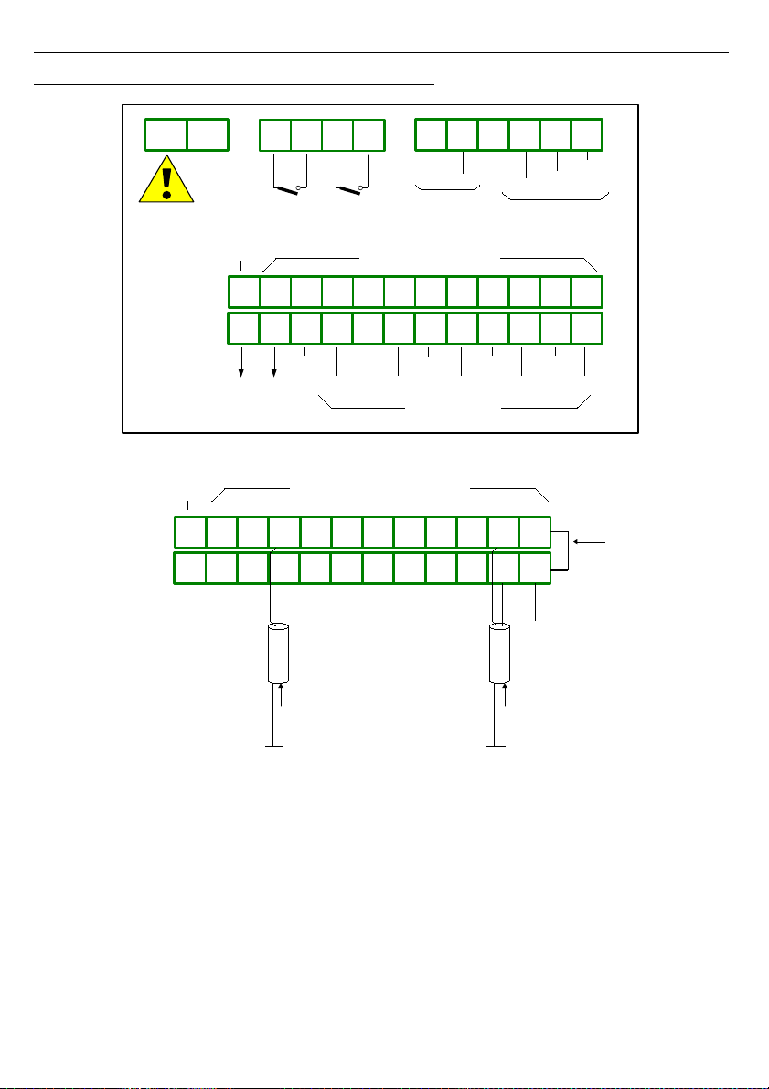
4.3.1.
Connections of current type inputs (
I version )
Fig. 4.10. Terminals description (
I version
)
Fig. 4.11. Connections of current signals of active sensors
(current signal 0-20 mA or 4-20 mA and ground)
16
additional terminals
(internally connected)
22 23 24 25 26
34 35 36 37 38
18 19 20 21
3328 29 30 31 3227
15 16 17
GND
AGND
external
GND
connection
input 1
4-20mA
input 8
4-20mA
. . . . .
1 2
22 23 24 25 26
34 35 36 37 38
Power supply
(depending
on version)
GND- RS
DATA+
DATA-
18 19 20 21
33
n.c.
28 29 30 31 3227
15 16 17
AGND
AIN8
AIN7
AIN6
AIN5
AIN4
AIN3
AIN2
AIN1
GND
+24V
GND
10 11 12 13 149
+24V
additional terminals
(internally connected)
current inputs
RS-485
Warning!
GND and AGND
internally connected
DIN+DIN-
digital input
6 754
ER1 ER2
Page 17
User manual - DATA RECORDER SRD-99 and cooperating software
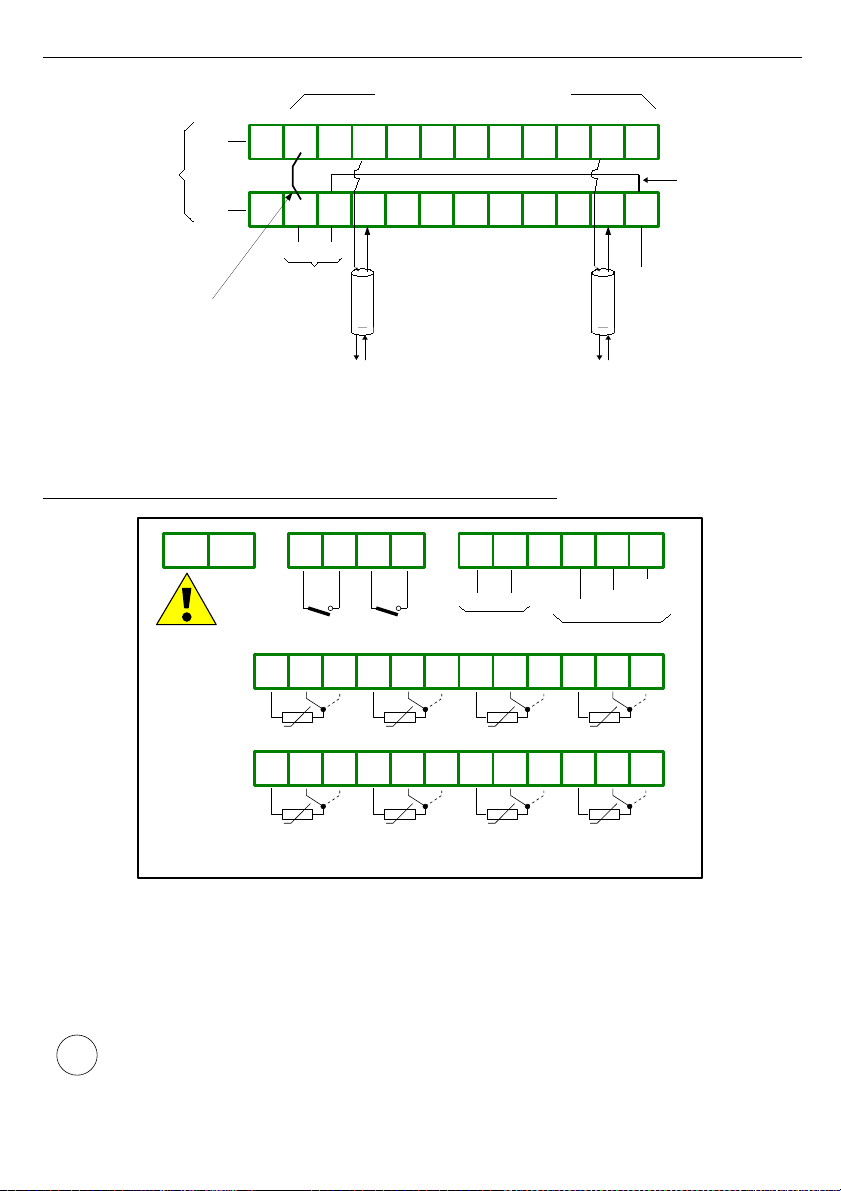
Fig. 4.12. Connections of current signals of 2-wire sensors
(sensor power supply voltage and 4-20 mA signal)
4.3.2.
Connections of temperature type inputs (
RTD version )
Fig. 4.13. Terminals description (
RTD version
)
The Pt100 / Pt500 / Pt1000 sensor can be connected to the device in typical 3-wire circuit
(
Fig. 4.14 a
) or 2-wire circuit (
Fig. 4.14 b
). Due to precision of measurement 3-wire circuit is
recommended.
If 2-wire circuit is used, the resistance of wires should be as small as possible, to
avoid of measurement errors. Measured value can be corrected (constant
correction) using „
Bias
” parameter from menu „
Input settings
”. Due to low
precision 2-wire connection is not recommended.
17
additional terminals
(internally connected)
22 23 24 25 26
34 35 36 37 38
18 19 20 21
3328 29 30 31 3227
15 16 17
GND
external
GND
connection
. . . . .
+
AGND
+
to sensor to sensor
external
sensor
supply
connection
+24V
sensor
supply
output
GND
+24V
sensor
supply
output
1 2
22 23 24 25 26
34 35 36 37 38
Power supply
(depending
on version)
18 19 20 21
3328 29 30 31 3227
15 16 17
AIN1÷AIN8: Pt100 / Pt500 / Pt1000 type inputs
AIN4AIN3AIN2AIN1
AIN8AIN7AIN6AIN5
6 754
GND- RS
DATA+
DATA-
n.c.
10 11 12 13 149
RS-485
DIN+DIN-
digital input
ER1 ER2
i
Page 18
User manual - DATA RECORDER SRD-99 and cooperating software
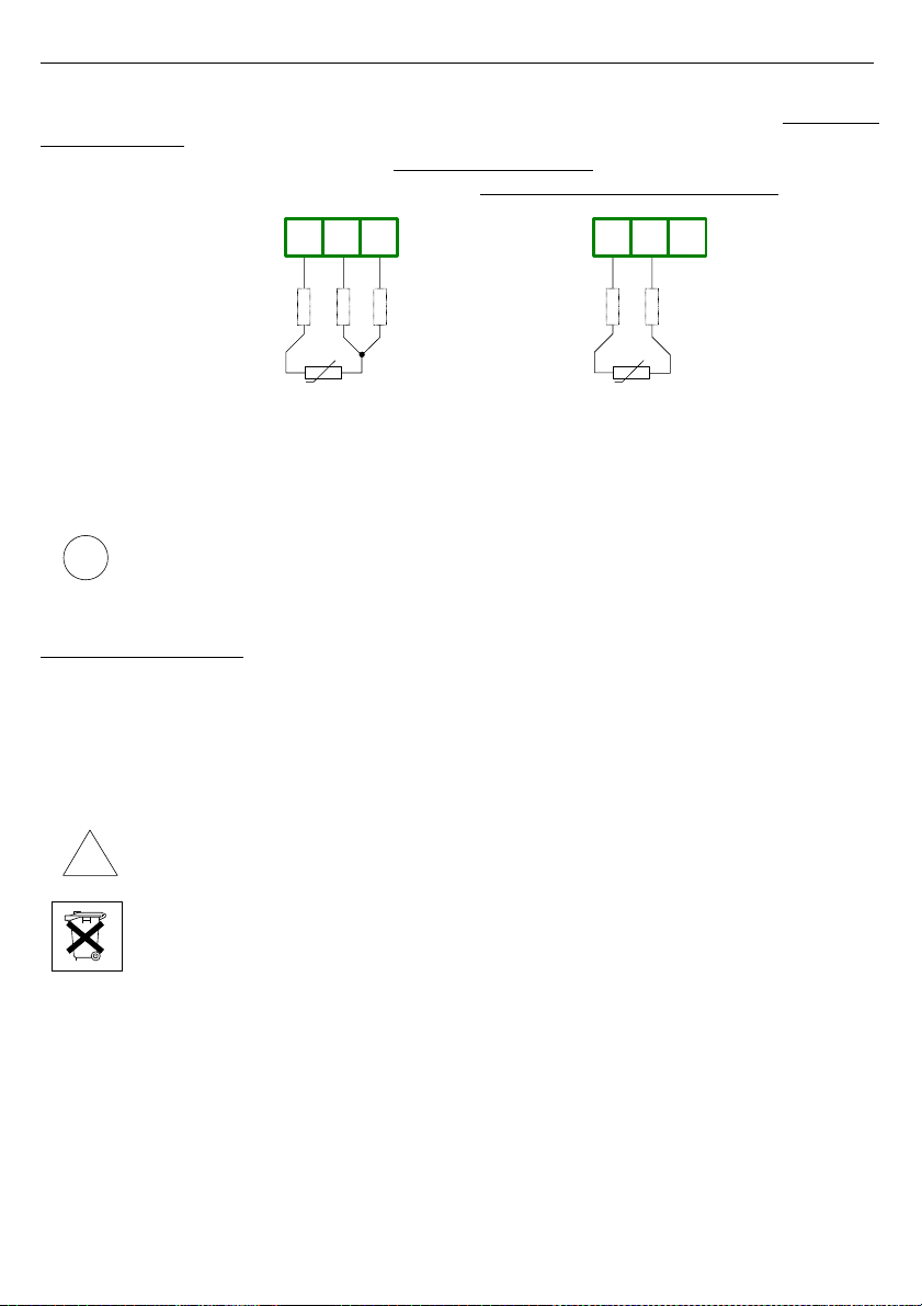
When 2-wires connection is used, the resistance of particular wires (Ra ÷ Rc)
NEEDN'T
BE DIFFERENT
(should be as small as possible) When 3-wires connection is used, the
resistance of particular wires (Ra ÷ Rc)
MUST BE IDENTICAL
to enable proper compensation
of it's resistance. The resistance of particular wire
should not be greater than 20
Ω
.
a) b)
Fig. 4.14. Connection of Pt100 sensors for channel no 1:
a) 3-wires circuit; b) 2-wires circuit;
The connection circuit should not be changed while unit is powered. Every change
of connection while the unit is powered causes measurement errors by several
seconds after change.
4.4. MAINTENANCE
The unit does not have any internal replaceable or adjustable components available to
the user. Pay attention to the ambient temperature in the room where the unit is operating.
Excessively high temperatures cause faster ageing of the internal components and shorten the
fault-free time of the unit's operation.
In cases where the unit gets dirty do not clean with solvents. For cleaning use warm water with
small amount of detergent or in the case of more significant contamination ethyl or isopropyl
alcohol.
Using any other agents can cause permanent damage to the housing.
Product marked with this symbol should not be placed in municipal waste. Please
check local regulations for disposal of electronic products.
18
!
i
Pt100
Ra Rb Rc
24 2625
Ra = Rb = Rc
Pt100
Ra Rb
24 25 26
Ra, Rb as small as possible
n.c.
Page 19
User manual - DATA RECORDER SRD-99 and cooperating software
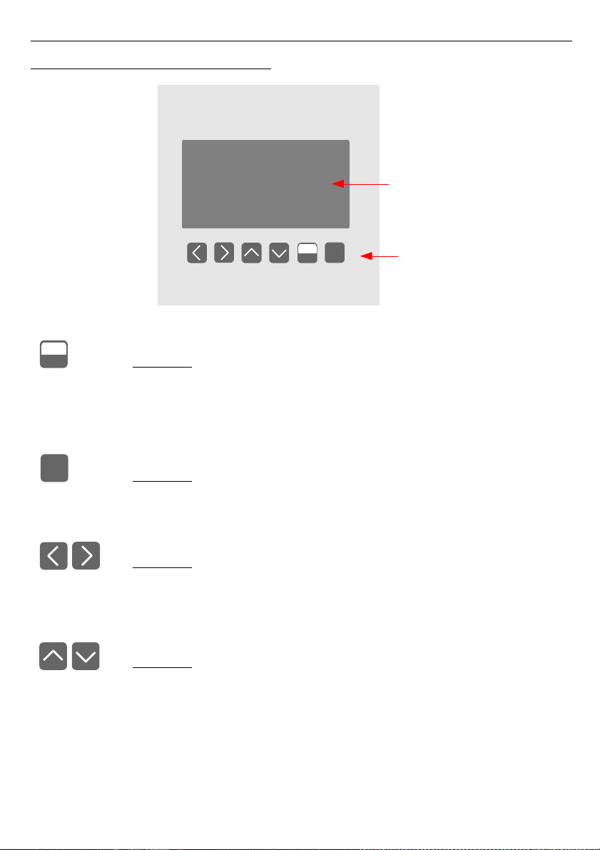
5. FRONT PANEL DESCRIPTION
Key designation and functions
Symbols used in the manual:
[ESC/MENU]
Functions:
• go to main menu (press and hold by at least 2 sec.),
• go to result presentation modes menu,
• exit the current level and return to previous menu (or to one of result
presentation modes),
• cancellation of changing the edited data logger parameter.
Symbols used in the manual:
[ENTER]
Functions:
• start editing parameter,
• go to submenu,
• confirm change of edited parameter.
Symbols used in the manual:
[<] [>]
Functions:
• change the horizontal cursor position,
• modify edited data logger parameter
• change of channel number in one of four result presentation modes and
during measurement channel configuration.
Symbols used in the manual:
[^] [v]
Functions:
• change the vertical cursor position,
• modify edited data logger parameter,
• change of channel result presentation mode.
19
MENU
ESC
ENTER
display
programming
pushbuttons
MENU
ESC
ENTER
Page 20
User manual - DATA RECORDER SRD-99 and cooperating software
6. PRINCIPLE OF OPERATION
After turning the power supply on, the logo and basic unit data are showed on the
display, then the unit goes to the measurement mode.
6.1. MEASUREMENT MODE
In the measurement mode the unit executes the measurement of values of signals
connected to measurement inputs, hereafter called measurement channels (the number of
available channels depends on the unit version). For each channel measurements are
conducted at the frequency of 8 times per second (I version
and
U version), 1 time per 2.5
seconds (RTD version) or 2 times per second (TC version). The results of the conducted
measurements are shown on the LCD display. The unit computes the measurement results
into indicated values proportionally (linear).
All available parameters of the unit’s operation can be configured in the main menu (see
DEVICE PROGRAMMING
) or using the RS-485 interface and software installed on your PC.
Configuration of the device (via menu or RS-485 interface)
do not stops the data
recording process .
Results of measurements conducted for active (selected by the user) channels of the unit are
displayed in one of the available result presentation modes (see
RESULT PRESENTATION
MODES
).
6.1.1.
Measurement ranges definition of current inputs
( I version )
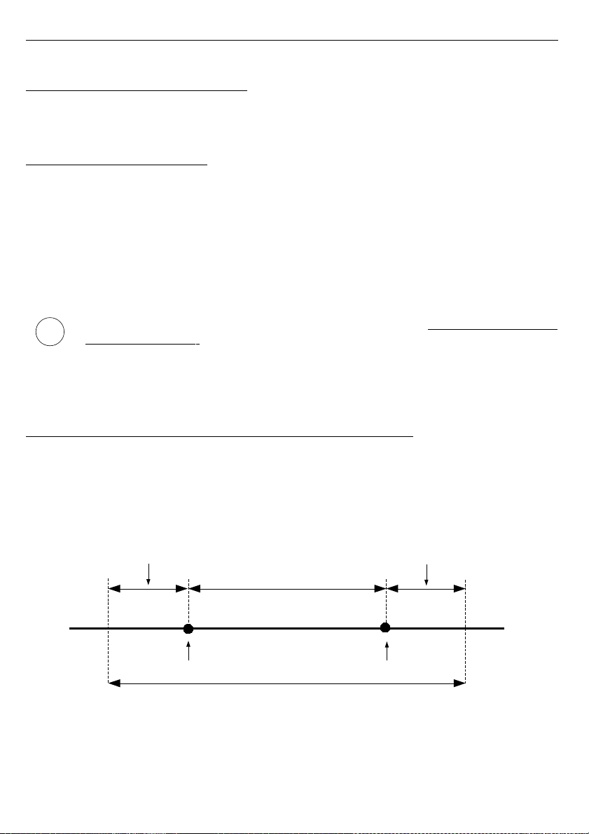
The nominal range of input current for each input is 0-20 mA or 4-20 mA and can be
extended to the maximum of 0-22 mA, independently to each measurement channel. The
range of measurement results corresponding to the nominal range of input current is defined
as
user defined range
. The range of measurement results corresponding to the range of input
current including the extensions is defined as
allowable measurement range
(
Fig. 6.1
). All
values presented as sliders are scaled due to
user defined range
. Graph is scaled due to
allowable measurement range
.
*
"Lower ext."
parameter is only significant for an input current range of 4-20 mA.
Fig. 6.1. Definition of measurement ranges (
I version
)
The range of displayed values, unit of measured value and position of the decimal point
(for presentation in numeric form) and name of channel are defined by the user.
20
user defined range
”Hi value” parameter
”Lo value” parameter
permissible measurement range
”Lower ext.” parameter
”Higher ext.” parameter
i
Page 21
User manual - DATA RECORDER SRD-99 and cooperating software
6.1.2.
Measurement ranges definition of voltage inputs
( U
version )
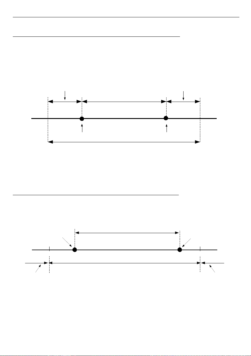
The nominal range of input current for each input is 0-5V, 1-5V, 0-10V or 2-10V and can
be extended to the maximum of 0-12 V, independently to each measurement channel. The
range of measurement results corresponding to the nominal range of input voltage is defined
as
user defined range
. The range of measurement results corresponding to the range of input
voltage including the extensions is defined as
allowable measurement range
(
Fig. 6.2
). All
values presented as sliders are scaled due to
user defined range
. Graph is scaled due to
allowable measurement range
.
*
"Lower ext."
parameter is only significant for an input current range of 1-5V and 2-10V.
Fig. 6.2. Definition of measurement ranges (
U version
)
The range of displayed values, unit of measured value and position of the decimal point
(for presentation in numeric form) and name of channel are defined by the user.
6.1.3.
Measurement ranges definition of RTD inputs
( RTD version )
The range of every input's measured signal is selectable, and user defined as
user
defined range
. All values presented in graphic form (graphs, sliders) are scaled due to
user
defined range.
The range of the results referred to maximum hardware performances is
defined as
allowable measurement range
(
Fig. 6.3
).
Fig. 6.3. Definition of measurement ranges (
RTD version
)
The range of the displayed values, type of input signal, scale bias, and name of the
channel are defined by the user.
21
”Hi value”
parameter
”Lo value”
parameter
user defined range
permissible measurement range
measurement result is displayed
regardless on nominal range exceeding
display
message ”-Lo-”
display
message ”-Hi-”
-100°C +600°C
user defined range
”Hi value” parameter
”Lo value” parameter
permissible measurement range
”Lower ext.” parameter
”Higher ext.” parameter
Page 22

User manual - DATA RECORDER SRD-99 and cooperating software
6.1.4.
Measurement ranges definition of TC inputs (
TC version )
The range of every input's measured signal is defined by selecting sensor type and
specified as
user defined range
. All values presented in graphic form (graphs, sliders) are
scaled due to
user defined range
. For thermocouple inputs there is no way to control this
range (
Fig. 6.4
).
Fig. 6.4. Definition of measurement ranges (
TC version
)
The range of displayed values, unit of measured value and position of the decimal point
(for presentation in numeric form) and name of channel are defined by the user.
6.1.5. Recording momentary and averaged data
Values corresponding to the results of current measurement conducted for each channel can
be recorded (stored in the non-volatile memory of the unit) for further analysis. The recording
of measurement results for all channels is performed with the same frequency, defined by the
user in the range between 1 record per second to 1 record per hour ("
Rec. period
"
parameter). Recording times are synchronized with the internal real time clock. Recording can
be stopped at any moment with selected status on digital input of the unit ("
Triggering
"
parameter).
In order to enable more advanced mathematical processing of recorded signals it is
possible to set the unit's options to record averaged measurement results. Setting the
recorded value type to
averaged value
(parameters "
Channel 1
"... "
Channel 8
", depending
on the number of channels in the unit) causes that instead of momentary values the unit
records in its memory values that constitute the average results of measurements conducted
during the set
recording period
. All measurements conducted by the unit shall be averaged,
irrespective of the set recording frequency.
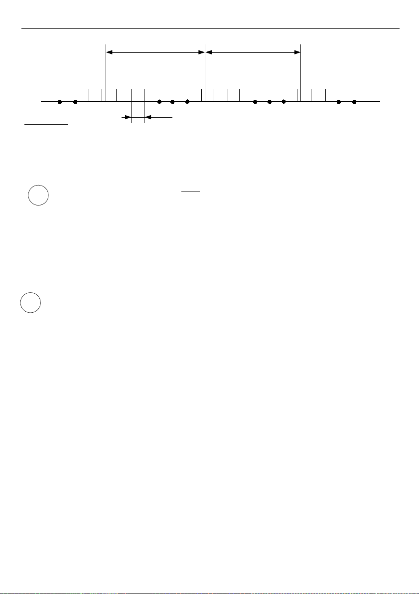
The principle of recording measurements is presented in
Fig. 6.5
. In the case of recording
momentary values
t(a), t(b), t(c)
designate the recording times of values corresponding to
current measurements
a
n
,
b
n
,
c
n
. In the case of recording averaged values
t(a), t(b), t(c)
designate the times of recording values corresponding to measurement averaging results,
a
1
…
a
n
,
b
1
…
b
n
,
c
1
…
c
n
correspondingly.
22
dopuszczalny zakres pomiarowy
Lo Hi
Page 23
User manual - DATA RECORDER SRD-99 and cooperating software
Explanation :
t(a), t(b), t(c) - recording points
a, b, c, d - measurement points
Δt - delay between measurements: 0.125s (
I version
) or 2.5s (
RTD version
)
Fig. 6.5. Principle of measurement recording
Averaging operation concerns
only
the type of recorded values; it does not concern
the method of presentation of current measurement. In all result presentation modes,
indications - described in the remaining part of the manual as results of
measurements not recorded in the unit's memory - correspond to the momentary
value of the measured signal.
Averaged values can be viewed in the data logger only in the "
Measurements list
" and
"
Graph
" results presentation mode, because these modes enable presentation of values
recorded in the unit's memory. Averaged values can also be viewed in the database
downloaded by the software working with the data logger.
In the case of multiple changes of type of recorded value (momentary values of
averaged values) there is no possibility to distinguish whether data recorded in the
memory concerns momentary measurement value or averaged measurement results.
Recording the measurement results in the non-volatile memory can be executed in two modes:
"
until full
" or "
cyclic
" ("
Write
" parameter). The first mode enables the recording of such
amounts of data as the unit's memory allows for, then the recording is stopped. In the second
mode, once the memory is full, the results are recorded from the starting address in the
memory, overwriting existing measurement results. The time remaining until the memory is full
is displayed once the unit is started and in the "
Device information
" menu, available in the
units main menu.
In the case of both modes, once the memory is full, a warning message is displayed (see
description of "
Write
" parameter in the "
Logging setup
" menu). The recorded data should be
periodically downloaded to a PC using appropriate software or USB FlashDrive (method
recommended for data loggers equipped with 8MB of memory).
All parameters concerning the recording m ode, the influence of digital input on the
recording method, the recording frequency and type of recorded value are available in the
"
Logging setup
" menu described in section
MAIN MENU DESCRIPTION
.
23
i
i
”Rec.period” parameter ”Rec.period” parameter
t(a)
t(c)
t(b)
a
n-1an
b
1
b
2
b
3
bnc
1
c2c
3
c
n
d
1
d
2
. . .
. . .
Δt
Page 24
User manual - DATA RECORDER SRD-99 and cooperating software
6.2. MODES OF RESULT PRESENTATION
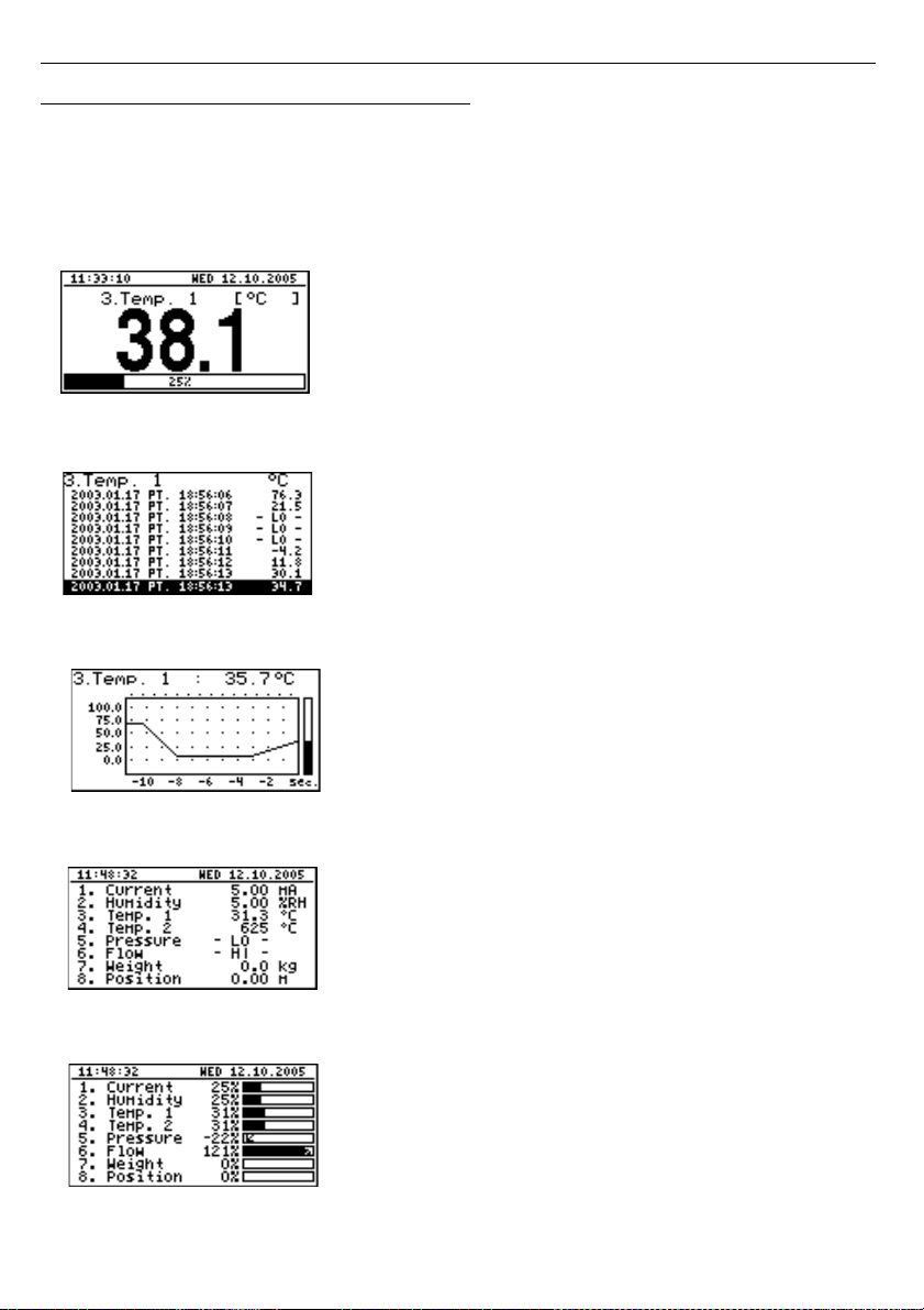
The results of measurements conducted for active channels are presented in numeric or
graphic (graph or bar) form. Selection of one of the available results presentation modes can
be made using the
[^]
and
[v]
keys in the measurement mode. Configuration of the method of
displaying in the selected results presentation mode can be made in the menu of the given
presentation mode (see
DESCRIPTION OF RESULTS PRESENTATION MODES MENU
). The
following presentation modes are available:
- "
Single channel
" mode (
Fig. 6.6
) enables the last
measurement for one of the measurement channels to be
viewed in the numeric and graphic form (bar).
Fig. 6.6. "Single channel" mode
- "
Measurements list
" mode (
Fig. 6.7
) enables the
momentary values recorded during the set period of time
or averaged values of the conducted measurements for
one of the measurement channels to be viewed in numeric
form.
Fig. 6.7. "Measurements list
" mode
- "
Graph
" mode (
Fig. 6.8
) enables the momentary values
or averaged values of measurements conducted for one of
measurement channels to be viewed in the form of a
graph.
Fig. 6.8. "graph" mode
- "
Channels list
" mode (
Fig. 6.9
,
6.10
) enables the
measurement results for all active measurement
channels to be viewed in numeric or graphic (bar) form.
Fig. 6.9. "Channels list" mode (values)
Fig. 6.10. "Channels list" mode (bars)
24
Page 25
User manual - DATA RECORDER SRD-99 and cooperating software
After starting the unit the result presentation mode and channel selected prior to
switching off the unit are active (this information is stored in the EEPROM memory)
6.2.1. "Single channel" mode
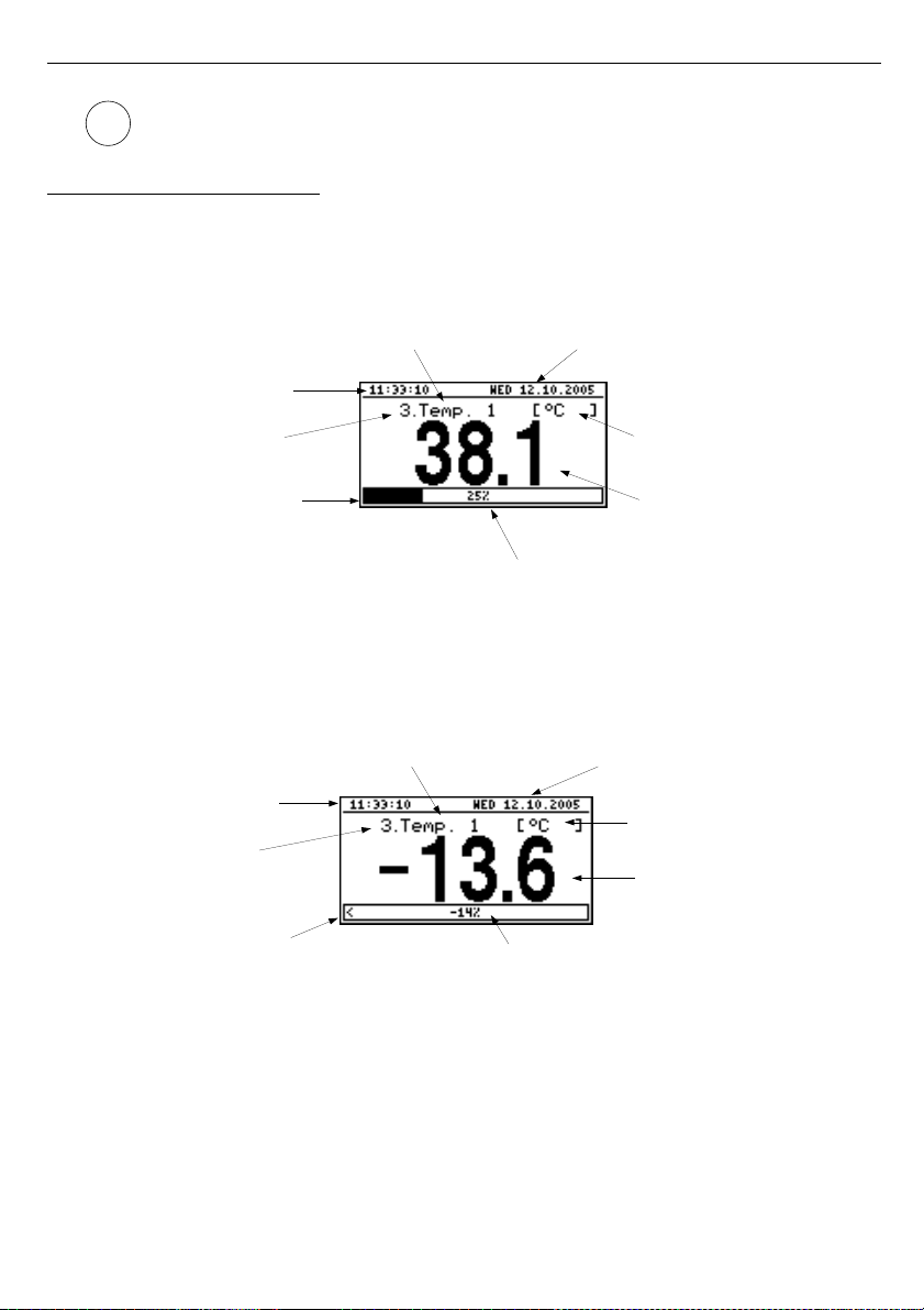
This mode (
Fig. 6.11
) displays the result of the last measurement for one of the active
channels in numeric form (in the middle part of the display) and in the form of a bar
(percentage, at the bottom of the screen). The graphical indicator (bar) always shows the
relation of the measurement result to the
user defined range
(see description of "
Hi value
",
"
Lo value
" parameters in the "
Inputs settings
" menu).
Fig. 6.11. Unit in ”Single channel” result presentation mode
Exceeding the user defined range (
Fig. 6.12
) is signalled on the bar with an arrow indicating
the direction of exceeding the range. If the measurement result for one channel exceeds the
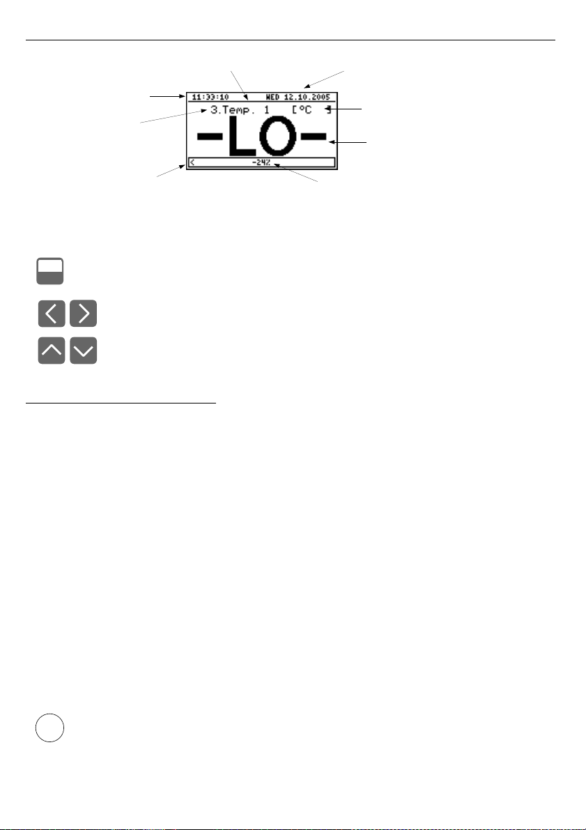
allowable measurement range (
Fig. 6.13
) instead of the result in numeric form the display
shows a
"-Hi-"
or
"-Lo-"
message (depending on the direction of exceeding).
Fig. 6.12. Exceeding user defined range in "Single channel" mode
25
i
channel name current date
unit name
measure result
in numerical mode
percentage rate of measure result to
user defined range
bargraph
channel number
current time
arrow indicates
exceeding
of user defined range
channel number
current time
percentage value of exceeding
unit name
measure result
in numerical mode
channel name current date
Page 26
User manual - DATA RECORDER SRD-99 and cooperating software
Fig. 6.13. Exceeding allowable range in "Single channel" mode
Functions of keys in "Single channel" mode:
• go to main menu (press and hold for approx. 2 seconds),
• change channel number,
• change results presentation mode.
6.2.2. "Measurements list" mode
The values displayed in this mode depend on the set type of recorded value (see
description of parameters "
Channel 1
"..."
Channel 8
" in the "
Logging setup
" menu).
In the case of recording momentary values in this mode (
Fig. 6.14
,
6.15
) the display shows
9 consecutive measurement results (including their execution time) in numeric form for one of
the active channels. It is possible to view the last recorded measurement results or results of
measurements recorded previously (depending on the "
List type
" parameter setting in the
"
Measurements list options
" menu). If the result of the measurement recorded for the given
channel exceeds
allowable measurement range
, instead of the result in numeric form the ”
-
Hi-
” or "
-Lo-
" message is displayed (depending on the direction of exceeding, see description
of "
Upper ext.
" and "
Lower ext.
" parameters in the "
Inputs settings
" menu). In order to go to
the "
Measurements list options
" menu press the
[ESC/MENU]
key.
If the "
List type
" parameter in the "
Measurements list options
" menu is set as "
current
"
(
Fig. 6.14
), the last of the displayed results (displayed in negative) concerns the current
measurement (not recorded). Above the result of the current measurement the display shows
the measurement recorded so far (stored in the non-volatile memory) for the given channel. If
there are no recorded measurements in the unit's memory at the moment, the list of recorded
measurements will be empty and only the result of the current measurement will be displayed.
Pressing the
[ENTER]
and
[^]
keys simultaneously allows list type to be switched from current
to historical.
Returning to the current list type is only possible from the "
Measurements list
options
" menu.
26
MENU
ESC
arrow indicates
exceeding
of user defined range
channel number
current time
channel name current date
percentage value of exceeding
unit name
warning message
informing that input allowable
range is exceeded
i
Page 27

User manual - DATA RECORDER SRD-99 and cooperating software
Fig. 6.14. Unit in “Measurements list” measurement results presentation mode.
“List type” parameter set as “current”.
If the "
List type
" parameter in the "
Measurements list options
" menu was set as "
historical
"
(
Fig. 6.15
), the last of the displayed results (displayed under the line) concerns the
measurement recorded at the time (or directly after it) defined by "
Date
" and "
Time
"
parameters in the "
Measurements list options
" menu. Above the line, the display shows
results of previously recorded measurements, i.e. before the time defined by "
Date
" and
"
Time
" parameters in the "
Measurements list options
" menu.
If there are no recorded measurements in the unit's memory, the list of recorded
measurements will be empty. Holding down the
[ENTER]
key and
[^]
or
[v]
key at the same
time allows the measurement list to be scrolled through.
Fig. 6.15. Unit in “Measurements list” measurement results presentation mode.
“List type” parameter set as “historic”.
When scrolling through the measurement list the "
List type
", "
Date
" and "
Time
" parameters in
the "
Measurements list options
" are set automatically depending on the time and date of the
currently displayed measurement results. The method of displaying shall be automatically
adjusted to the new values of these parameters.
If the setting of "
Date
" and "
Time
" parameters in the "
Measurements list options
"
menu shall be later than the current date and time defined by "
Date
" and "
Time
"
parameters in "
Date & time settings
" menu (calling parameters recorded "in future")
the display will only show the list of measurement results recorded so far and the
"
Date & time settings
" parameters shall be automatically reset to date and time
values of the latest measurement.
27
i
channel number
recording
date and time
date and time of
current measurement
(not recorded yet)
channel name
unit name
recorded overload
recorded
measurements
current measurement
(displayed in negative mode)
channel number
recording
date and time
measurement registered
at (or after) time point
defined by „Date“ and
„Time“ parameters
channel name
unit name
recorded overload
measurement registered
before time point
defined by ”Date” and
”Time” parameters
Page 28

User manual - DATA RECORDER SRD-99 and cooperating software
In the case of recording averaged values all indications in the "
Measurements list
" mode
concerning values recorded in the unit's memory, constitute averaged values of measurement
results. The current value indications concern only momentary measurement values.
During the recording of averaged values of measurement results, the exceeding of the
allowable measurement range
is understood as exceeding this parameter by at least one
from the current measurements incorporated into the averaging.
In the case of exceeding the upper limit, lower limit, or both limits of the measurement range in
the given
recording period
, values represented in the form of "
-Hi-
", "
-Lo-
" or "
-Hi/Lo-
"
messages will be recorded in the unit's memory instead of averaged results.
Fig. 6.16. Message displayed while downloading data to be displayed
During the download of data to be displayed from the unit's memory (recorded
measurement results), an appropriate message is displayed instead of the
measurement result (
Fig. 6.16
). "X" is displayed for data that has not been
downloaded yet.
Functions of keys in "Measurements list" mode:
• go to main menu (press and hold for approx. 2 seconds),
• go to "
Measurements list options
" menu, description on page 42.
• change channel number,
• change results presentation mode.
• scroll through measurement list (for historical list),
• switching list type from current to historic (for current list).
28
i
MENU
ESC
+
ENTER
message informing
that data is being
readed from memory
”X” signs displayed
for data not readed yet
Page 29
User manual - DATA RECORDER SRD-99 and cooperating software
6.2.3. ”Graph” mode
Values displayed in this mode depend on the set type of recorded value (see description
of parameters "
Channel 1
"..."
Channel 8
" in the "
Logging setup
" menu).
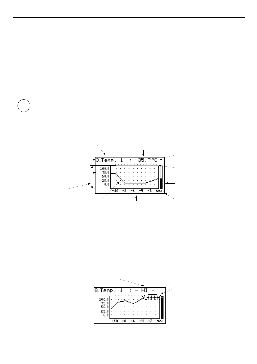
In the case of recording momentary values in this mode (
Fig. 6.17
) the display shows
measurement results in the form of a graph, numeric form and in the form of a vertical bar.
Numeric values (displayed over the graph) and vertical bar (displayed to the right of the graph)
indicate the value corresponding to the result of the current measurement, irrespective of the
set time scale of the graph. The graphical indicator (bar displayed to the right of the graph)
always indicates the measurement result to the
graph scale range
ratio (see description of
"
Hi value
" "
Lo value
" parameters in the "
Inputs settings
" menu).
Depending on measurement inputs type
graph scale range
is defined as:
• for I version -
graph scale range
=
allowable measurement range
• for U version -
graph scale range = allowable measurement range
• for RTD version -
graph scale range
=
user defined range
• for TC version
-
graph scale range = allowable measurement range
Fig. 6.17. Unit in "Graph" result presentation mode
Exceeding the
graph scale range
(
Fig. 6.18, 6.19
) is announced on the bar in the form of an
arrow indicating the direction of exceeding the range. If the measurement result for the given
channel exceeds the
graph scale range
(
Fig. 6.18, 6.19
) instead of the current numeric value
(displayed in the upper right corner) the display shows a "
-Hi-
" or "
-Lo-
" message (depending
on the direction of exceeding).
Fig. 6.18. Exceeding the upper limit of the graph scale range
29
warning message informing that input
graph scale range is exceeded
arows inform that
graph scale range
is exceeded
channel number
vertical axis (values)
graph scale
range
measure result
in graphical mode (graph)
horisontal axis (time)
time unit
bargraph
points of registration
unit name
channel name measure result
in numerical mode
i
Page 30
User manual - DATA RECORDER SRD-99 and cooperating software
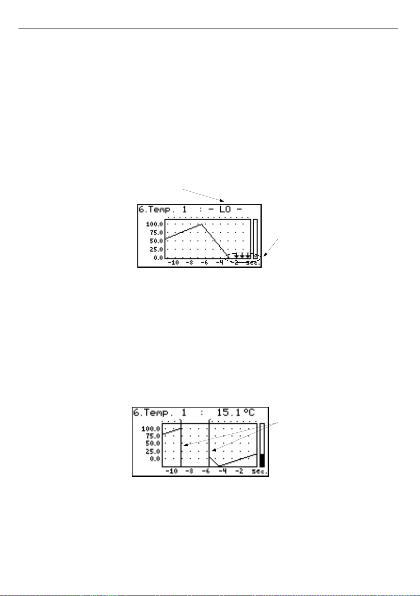
The display shows points corresponding to measurement results. Directly after switching
to the "
Graph
" mode the display shows points of the graph corresponding to measurement
results recorded so far. The points that are displayed next, correspond to the results of
conducted measurements. Therefore, if there are recorded measurement results in the unit's
memory, they shall be displayed directly after switching to the "
Graph
" mode, otherwise (no
recorded measurements) the graph points corresponding to measurements results shall be
plotted from the time this mode is switched on. If the measurement result for the given channel
exceeds the
graph scale range
, then instead of the graph point corresponding to the
measurement result, the display shows an arrow indicating the direction of exceeding the
range (
Fig. 6.18
,
6.19
). Above the upper limit of graph window the display shows points
corresponding to the measurement recording times.
The vertical scale of the graph covers the values defined for the
graph scale range
.
Fig. 6.19. Exceeding lower limit of the graph scale range
In the case of recording averaged values all points of the graph, concerning values recorded in
the unit's memory, constitute averaged measurement results. Indicators (numeric, bar) and
points of the graph, corresponding to current values refer to the momentary measurement
value.
When recording averaged measurement results exceeding the
allowable measurement
range
is understood as exceeding of this range by at least one of the measurements to be
averaged.
In the case of the upper limit, lower limit, or both limits of measurement range being exceeded
in the given
recording period
, values represented in the form of arrows indicating the
direction of exceeding (up, down, or both directions) will be recorded in the unit's memory
instead of the averaged results.
Fig. 6.20. Breaks in registration or change of configuration in "Graph" mode
Changes of settings configuring the operation of a given channel and operation stoppage are
signalled in the form of a vertical line (
Fig. 6.20
).
30
vertical line informs about breaks
in registration (power turn off) or
configuration change
warning message informing that input
graph scale range is exceeded
arows inform that
graph scale range
is exceeded
Page 31
User manual - DATA RECORDER SRD-99 and cooperating software
If the settings of the horizontal scale (time scale) will be too big (time/point) in relation
to speed of changes of the measurement signal, the graph can become illegible. If
this is the case, change the time scale settings. The horizontal scale settings (time
scale) can be changed in the "
Graph options
" menu. In order to go to the
"
Graph options
" menu press the
[ESC/MENU]
key.
Functions of keys in "Graph" mode:
• go to main menu (press and hold for approx. 2 seconds),
• go to "
Graph options
" menu, description on page 43,
• change channel number,
• change results presentation mode.
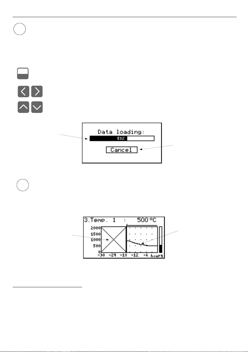
Fig. 6.21. Message displayed when loading data to be displayed on the graph
If downloading the data (recorded measurement results) necessary for displaying the
graph takes more than 1 second an appropriate message is displayed (
Fig. 6.21
).
Pressing
[ENTER]
will stop the data downloading process and display a graph made
on the basis of the data downloaded so far. "X" will be displayed instead of data that
was not downloaded (
Fig. 6.22
).
Fig. 6.22. Display in "Graph" mode in the case where data download was stopped.
6.2.4. ”Channels List” mode
In this mode (
Fig. 6.23, 6.24
) the display shows the results of the current measurements
for the active channels of the unit. The measurement results can be presented in numeric form
or in the form of a bar (percentage) depending on the settings in the "
Channels list options
"
menu. Graphic indicators (bars) always show the measurement result to the
user defined
range
ratio.
31
i
i
Progress bar
pressing of [ENTER] button
stops data downloading
”X” sign displayed
instead of data that was
not downloaded
graph created
from downloaded
data
MENU
ESC
Page 32
User manual - DATA RECORDER SRD-99 and cooperating software
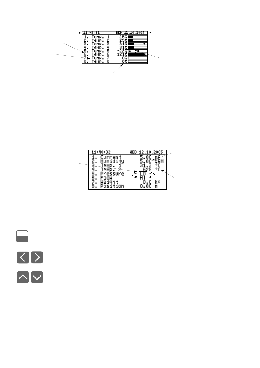
Fig. 6.23. Unit in "Channels list" results presentation mode.
"Channels list options" parameter set as "bar graphs".
Exceeding the
user defined range
is signalled on the bars in the form of an arrow
indicating the direction of exceeding the range. If the measurement result for a given channel
exceeds the
allowable measurement range
, instead of the current result in numeric form the
display shows a "
-Hi-
" or "
-Lo-
" message (depending on the direction of exceeding). Press the
[ESC/MENU]
key to go to "
Channels list options
" menu.
Fig. 6.24. Unit in "Channels list" results presentation mode.
"Channels list options" parameter set as "values".
Functions of keys in "Channels list" mode:
• go to main menu (press and hold for approx. 2 seconds),
• Go to "
Channels list options
" menu, description on page 43.
• change channel number,
• change results presentation mode.
32
MENU
ESC
current time
channel number
channel name
percentage rate of measure result to
user defined range
current date
measure result in graphical
mode (bargraph)
arrow informs about direction of
user defined range exceeding
warning message
informing that input allowable
range is exceeded
measure result in
numerical mode
unit name
Page 33
User manual - DATA RECORDER SRD-99 and cooperating software
6.3. PRINCIPLE OF OUTPUTS OPERATION
Device is equipped in electronic relay outputs that can be used to control external
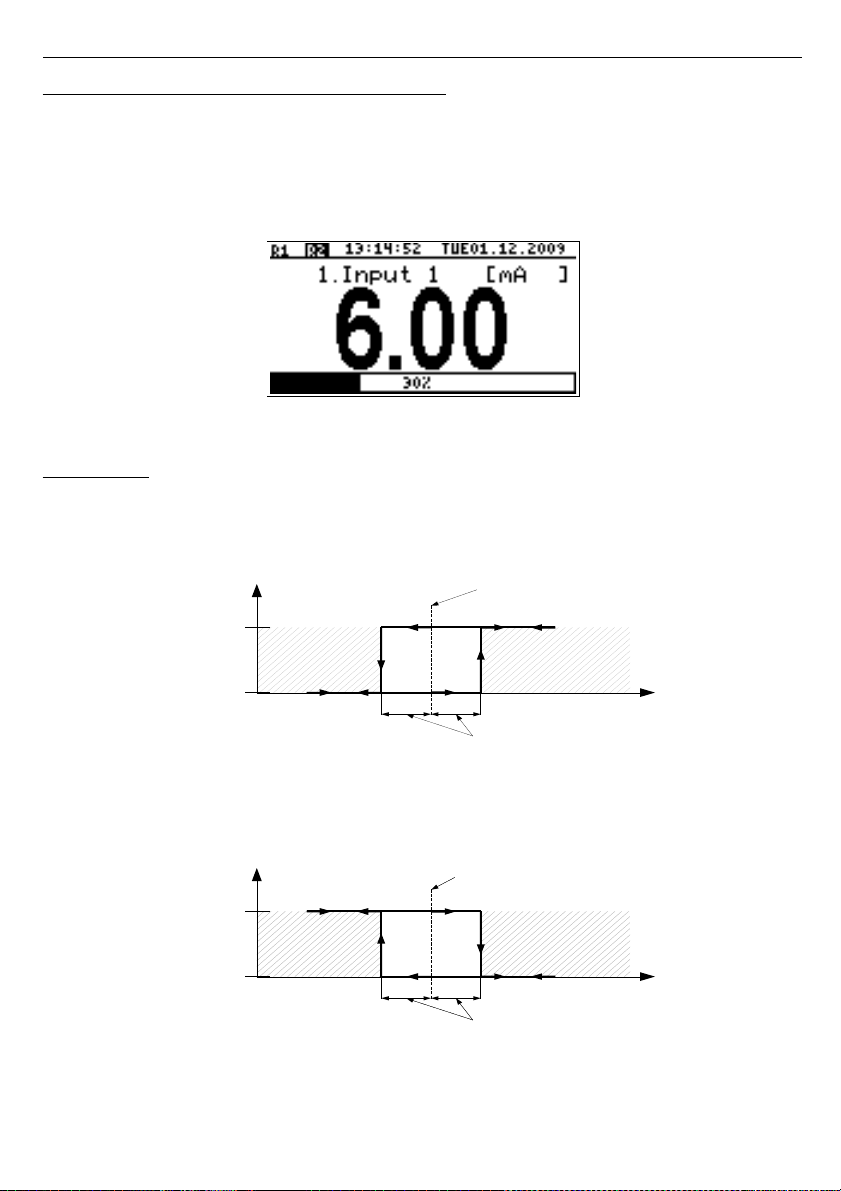
devices. Each output has own icon (in left upper corner
Fig. 6.25
) that shows the status of the
output.
Relays are controlled by alarms defined in ”
Inputs settings
” menu and additional
parameters in ”
Outputs settings
” menu.
Fig. 6.25. Screen with relay 1 open and relay 2 closed.
6.3.1. Alarms
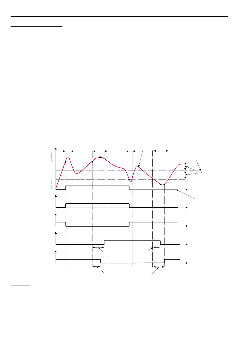
Each channel can generate two independent alarms. Particular alarm is present when
entered condition is met. Those conditions can be set in ”
Inputs settings
”.
Fig. 6.26. ”Over threshold” mode diagram. 0 means alarm not present, 1 alarm present
Fig. 6.27. ”Under threshold” mode diagram. 0 means alarm not present, 1 alarm present
33
Under
threshold
Over
threshold
1
0
Alarm state
”Threshold” parameter
”Hysteresis” parameter
Reading
Under
threshold
Over
threshold
1
0
Alarm state
”Threshold” parameter
”Hysteresis” parameter
Reading
Page 34
User manual - DATA RECORDER SRD-99 and cooperating software
6.3.2. Outputs control
Device outputs are controlled by logic function of channels alarms. There are two logic
functions: OR – closes (or opens, if output channel mode is set to N.C.) the relay when
any
of
attached channels is in alarm state, AND - closes (or opens, if output channel mode is set to
“
N.C.
”) when
all
of attached channels are in alarm state.
A particular channel is in alarm state when condition selected in ”
Outputs settings:
Source
” is met. For example when ”
alarm 2
” option is selected for channel 1 the channel 1 will
be in alarm state
if and only if
alarm 2 will be present, state of alarm 1 does not mater in this
case. If option „
alarm 1 and 2
” is selected, channel will be in alarm state
if and only if
alarm 1
and
alarm 2 will be present in the same time.
”
Mode
” parameter describes output mode. If ”
N.O.
” is selected then relay will be closed
when logic function is 1, and open in the other case. If ”
N.C.
” is selected then relay will be
open when logic function is 1 and closed in the other case.
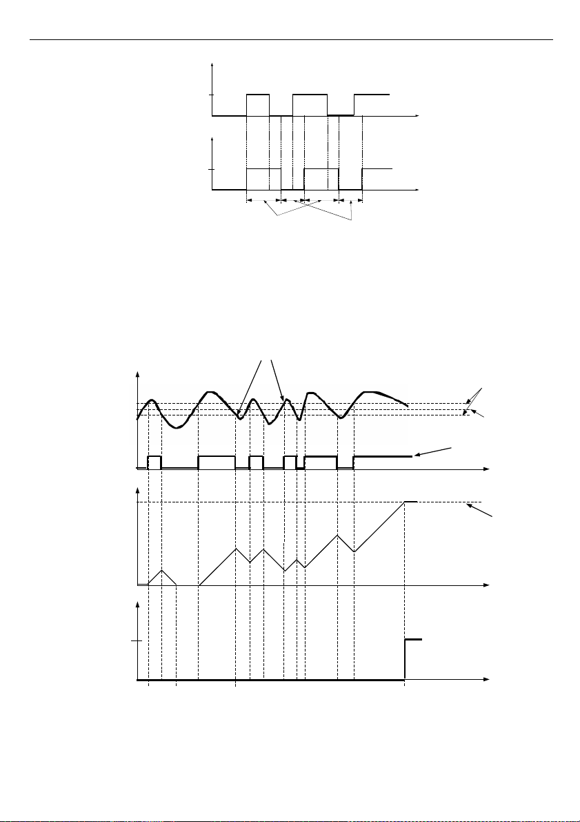
Fig. 6.28
shows example reading fallowed by rely state. Rely state can be changed only
when times (tA ,tB ,tC ,tD ) are greater than delays times. If those delays times are set to ”0” the
switch state is taken as soon as condition appears. If those delay parameters are set to value
greater than ”0” relay switch state is taken (point B
ON
, D
ON
, chart: a, d, e) when delay time is
elapsed.
Caption:
A, B, C, D, E –
signal border crossing points.
B
ON
,
B
OFF
,
C
ON
,
C
OFF
,
E
ON
,
E
OFF –
relay switch state moments for chart d and e
t
A
,
t
B
,
t
C
,
t
D
,
t
E –
times when displayed values are in measurement zones Over and Under threshold
Fig. 6.28. Relay controlled by one alarm ”Over threshold” mode
(”Closed hold time and ”Open hold time” set to 0).
34
”Threshold”
parameter
”Hysteresis”
parameter
Signal
Reading
time
A
B
C
D
Output state
mode = N.O.
Close delay=0
Open delay=0
t
A
t
B
t
C
t
D
B
ON
D
OFF
Open delay
Close delay
B
OFF
D
ON
a)
b)
c)
d)
e)
Over
threshold
closed
open
Under
threshold
Logic
function
Close delay
Open delay
time
time
time
Output state
mode = N.C.
Close delay=0
Open delay=0
Output state
mode = N.O.
Close delay>0
Open delay>0
Output state
mode = N.C.
Close delay>0
Open delay>0
closed
closed
closed
open
open
open
time
Page 35
User manual - DATA RECORDER SRD-99 and cooperating software
Fig. 6.29. Working relay diagram in ”N.O.” mode. ”Open hold time”
and ”Closed hold time” greater than 0, ”Open delay” and ”Close delay” equals 0.
Additional parameters shown in
Fig. 6.30
are ”
Closed hold time
” and ”
Open hold time
”.
Those parameters cause current output state to hold for desired time. When output is hold
alarms states are no consider therefore no delays times are counted until hold time elapsed.
Fig. 6.30. Working output controlled by single channel alarm with large reading oscillations.
Alarm mode - ”over threshold
”, ”
Open hold time
” and ”
Closed hold time” equals 0,
”Open delay
” and
”
Close delay
”
greater 0.
35
Relay
state
open
closed
time
Time
counter
”Open delay”
parameter
Overpass
A
B
C D
Threshold
Hysteresis
Reading
alarm/Logic
function state
time
time
Relay state
Logic
function
Close hold time
Open hold time
0
1
Open
Closed
time
time
Page 36

User manual - DATA RECORDER SRD-99 and cooperating software
In case of often threshold overpass (large readings oscillations) the ”
Close delay
” and
”
Open delay
” parameters in opposite to ”
Closed hold time
” and ”
Open hold time
” will delay
switching output state until internal time counter reaches entered value. The counter is
counting up (to the entered value) when logic function is 1 and counting down to 0 when logic
function is 0. The way how it works is described in
Fig. 6.30
.
6.3.3. Example of output control
Outputs have limited current rating.
Do not
use outputs to supply external
devices that requires a lot of power like heaters, motors or others. Instead, use
external supply devices like power relays or others that can be controlled by
output.
If simple temperature control in some room is required this device can be used to do this.
Assuming there is a heater and cooler that we can control by outputs and single temperature
sensor. We must connect a sensor to some input, output 1 to control the heater and output 2
to control the cooler. The input channel where temperature sensor is connected must be
configured correctly (in this example it is assumed reading is in Celsius degree).
If lower limit of the temperature when heater should be turned on is 18 degree and upper
limit when cooler should be turned on is 27 degree, alarm settings should be as follows
(assuming decimal point ”
0.0
”):
”
AL1 mode
” - ”
under threshold
”
”
Threshold 1
” -
19.0
”
Hysteresis 1
” -
1.0
”
AL2 mode
” - ”
over threshold
”
”
Threshold 2
” -
26.0
”
Hysteresis 2
” -
1.0
When alarm 1 is generated this means that the temperature reaches 18 degree (
19.0
–
1.0).
When temperature reaches 20 degree (
19.0+1.0
) alarm 1 will disappear. Similar, when
temperature reaches 27 degree (
26.0
+
1.0
) alarm 2 will appear and when temperature
reaches 25 degree (
26.0
–
1.0
) alarm 2 will disappear.
Now we have to configure outputs to use those alarms. In ”
Outputs settings
” menu
fallowing example parameters must be set:
Output 1 (heater control)
”
Mode
” - ”
N.O.
”
”
Logic funct.
” - ”
AND
”
”
Source:channel 1
” - ”
alarm 1
” - heater alarm
”
Close delay
” - ”
120.0
” - heater turning on delay
”
Open delay
” - ”
30.0
” - heater turning off delay
”
Closed hold time
” - ”
180.0
” - minimal time that heater should work
”
Open hold time
” - ”
150.0
” - minimal time that heater should be turned off
36
!
Page 37
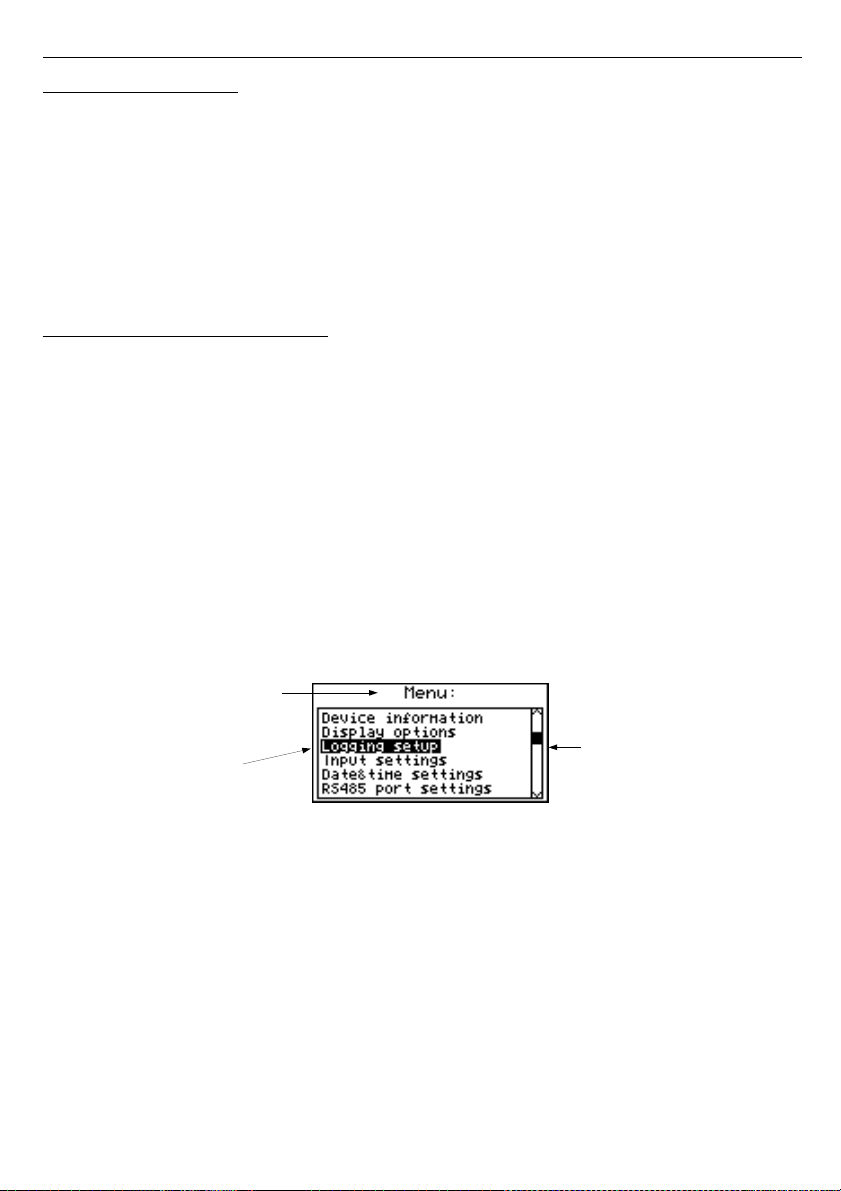
User manual - DATA RECORDER SRD-99 and cooperating software
Output 2 (cooler control)
”
Mode
” - ”
N.O.
”
”
Logic funct.
” - ”
AND
”
”
Source:channel 1
” - ”
alarm 2
” - cooler alarm
”
Close delay
” - ”
120.0
” - cooler turning on delay
”
Open delay
” - ”
30.0
” - cooler turning off delay
”
Closed hold time
” - ”
180.0
” - cooler time that heater should work
”
Open hold time
” - ”
150.0
” - cooler time that heater should be turned off
For those settings the heater and cooler will work as assumed.
7. DEVICE PROGRAMMING
Defining the method of displaying measurement results in the selected results
presentation mode can be done in the presentation mode menu. The meaning of individual
parameters available for selected modes of results presentation is described in the
DESCRIPTION OF RESULTS PRESENTATION MENU MODES
section. In order to get to the
configuration menu of selected results presentation mode, press the
[ESC/MENU]
key in the
current results presentation mode.
The unit's main menu (
Fig. 7.1
) enables necessary information about the unit to be
obtained and allows the setting of all parameters of the unit related to operation of
measurement channels, communications using the RS-485 interface, LCD display, access
settings, and other. The meaning of particular parameters of the unit is described in section
MAIN MENU DESCRIPTION
.
To access the main menu press down and hold for approx. 2 seconds the
[ESC/MENU]
key in any results presentation mode.
Fig. 7.1. Main menu of the unit
If the "
Password
" option in the "
Access setup
" menu was defined, then the user will
have to provide the password (
Fig. 7.2
) before proceeding to menu options (the password is
entered the same way as changing a numeric parameter, see
EDITING PARAMETERS
).
37
list position
indicator
presently selected
menu item (submenu)
current menu name
Page 38
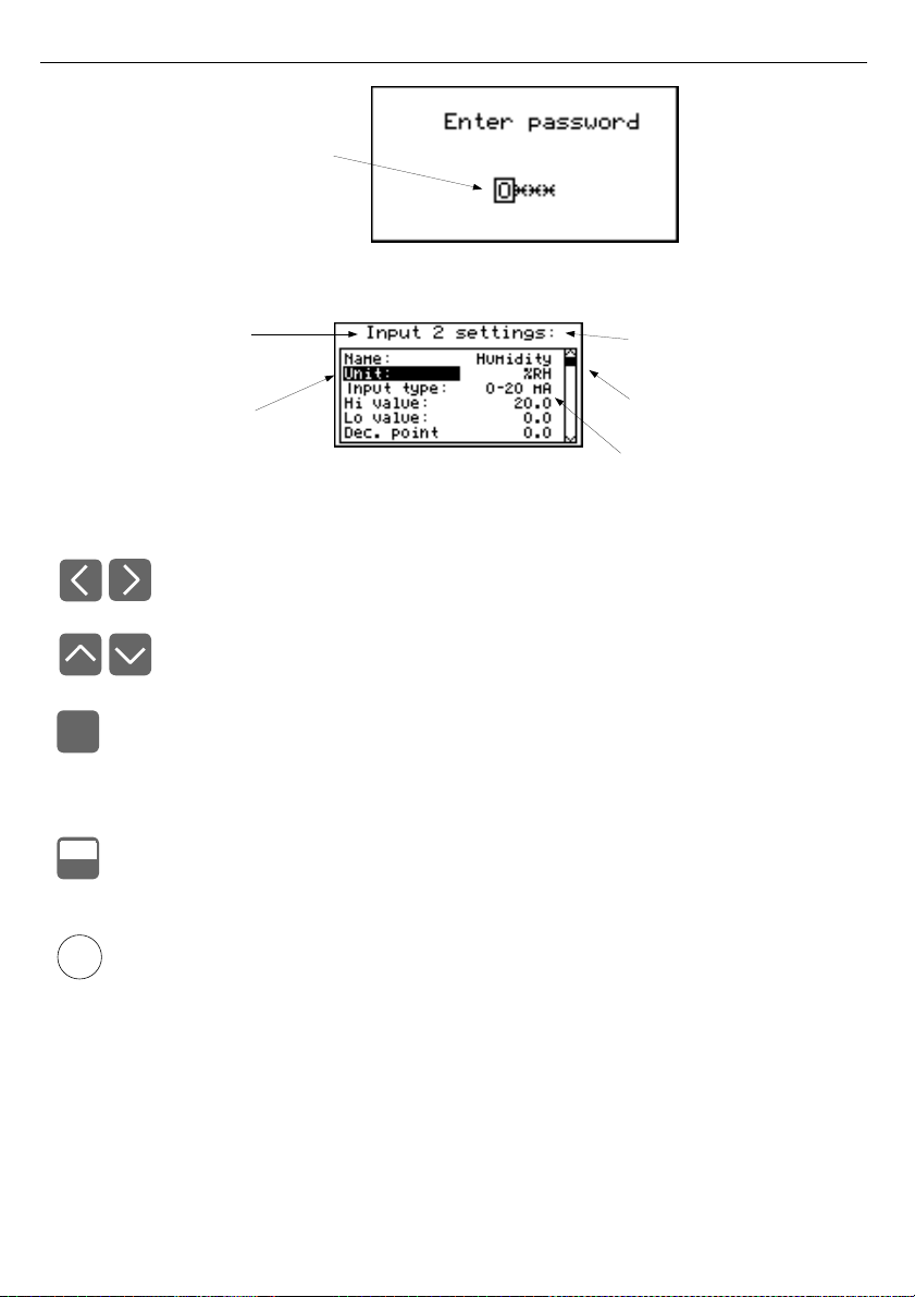
User manual - DATA RECORDER SRD-99 and cooperating software
Fig. 7.2. Password requested when accessing unit's main menu.
Fig. 7.3. Example of submenu
Functions of the buttons while sub-menu and parameters choice:
• Change the number of the configured channel (only in "
Inputs settings
"
submenu.
• Change of current item in the menu (selecting a lower level menu or
parameter for editing). The selected option is distinguished by displaying
the option name in negative (bright lettering on dark background).
The function of the
[ENTER]
key depends on the type of current menu item:
• if the menu item corresponds to one of the unit's parameters, pressing
[ENTER]
starts parameter editing,
• if the menu item selects a lower level menu, pressing
[ENTER]
activates
the new menu.
• The
[ESC/MENU]
key exits the current menu level and returns to a higher
order menu (to one of the results presentation modes).
After approximately 1 minute since the last activation of the keys, the unit returns from
any level to one of the results presentation modes (only if no parameters are in
editing mode).
38
i
ENTER
MENU
ESC
edited password position
is outlined and blinking
current submenu name
presently selected
item (edited parameter)
presently configured
measurement channel
number
list position
indicator
current settings
Page 39

User manual - DATA RECORDER SRD-99 and cooperating software
7.1. PARAMETERS EDITION
To start edition of any parameter user should select name of desired one using
[^] [v]
buttons and then
[ENTER].
7.1.1. Numeric and switching parameters ("LIST" - type)
Numeric parameters constitute a series of digits that form a number in decimal format.
Entering a new parameter value (
Fig. 7.4
) consists of changing the values of selected digits
within the allowable range (using the
[^]
,
[v]
keys). Some numeric parameters can take
negative values (e.g. "
Hi value
" parameter). In such cases the "-" mark can be selected on the
first decimal position of the parameter.
Switching parameters (
Fig. 7.5
) can be presented in the form of a list, out of which only
one of the options available on the list can be selected for the given parameter. Options of
switching parameter are selected using
[^], [v]
keys.
Fig. 7.4. Editing numerical parameter
Fig. 7.5. Editing "LIST" - type switching parameter
Functions of keys when editing numeric and switching parameters:
• Selecting the decimal position of the edited numeric parameter. Selected
item is distinguished with brackets and flashes. In the case of switching
parameters these keys are not used.
• Change of current value (i.e. flashing) of the digit (for numeric parameters)
or switching status (for switching parameters, e.g. "
Input type
").
• Confirm the changes and end parameter editing.
• Cancel changes.
39
ENTER
MENU
ESC
selected numerical
parameter
edited numerical parameter
position is outlined and blinking
selected LIST-type
parameter
edited switch parameter
is outlined and blinking
Page 40
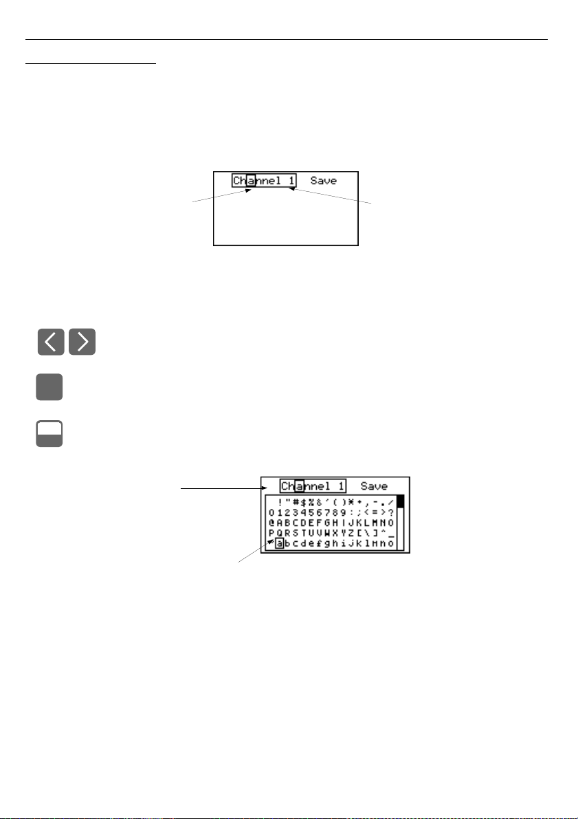
User manual - DATA RECORDER SRD-99 and cooperating software
7.1.2. Text parameters
Text parameters constitute a series of characters selected from the character table
(
Fig. 7.7
) stored in the unit's memory. Entering the new parameter value (
Fig. 7.6
,
7.7
)
consists of selecting consecutive characters of the text by indicating the position of the
character in the table displayed below edited text. The edited character is placed in brackets
and flashes; its source is indicated in the characters table with brackets surrounding the edited
character.
Fig. 7.6. Selection of character for editing
Functions of keys when selecting character for editing (characters table is not
displayed at that time):
• Selecting the position of edited character or option of saving text parameter.
The selected character (save option) is distinguished with brackets.
• Start editing the character for the selected position
• Confirm the changes and finish parameter editing (when option "
Save
" is
distinguished with brackets and flashes).
• Cancel changes (at any time).
Fig. 7.7. Character editing
40
ENTER
MENU
ESC
edited position is
outlined and blinking
edited text parameter (label)
edited position is outlined
and blinking
selected charakter is outlined
Page 41
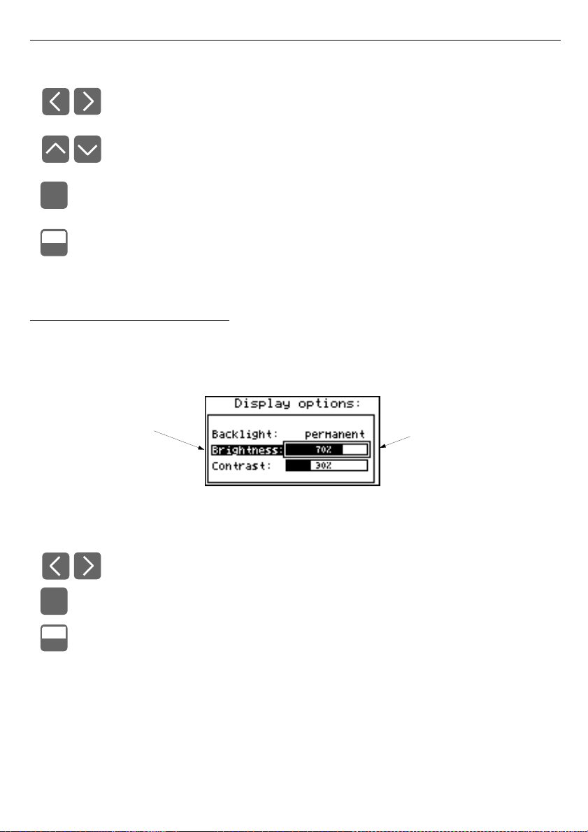
User manual - DATA RECORDER SRD-99 and cooperating software
Functions of keys when editing selected character
(at this time characters table is displayed below the edited parameter):
• Selecting the character from the given line of characters table for the edited
position of the text parameter.
• Selecting the character from the given column of characters table for the
edited position of the text parameter.
• Confirm the selected character from characters table for the edited position
and start editing next character or completing character editing (if the edited
character was the last one in the sequence).
• Cancel changes (at any time).
7.1.3. “SLIDER” - type parameters
The parameters of this type are presented graphically in the form of a bar that turns black
correspondingly to the ratio of the current value of the selected parameter to the maximum
value of this parameter. Entering the new parameter value (
Fig. 7.8
) consists of changing the
level of "blackening" the bar within the allowable range using the
[<], [>]
keys.
Fig. 7.8. Editing "SLIDER" - type parameter
Functions of keys when editing "SLIDER" - type parameters:
• Change the value of edited parameter. The edited parameter placed in
brackets and flashes.
• Finish editing parameter.
• Cancel changes (at any time).
41
ENTER
MENU
ESC
ENTER
MENU
ESC
SLIDER-type parameter
edited parameter is outlined
and blinking
Page 42

User manual - DATA RECORDER SRD-99 and cooperating software
7.2. DESCRIPTION OF RESULTS PRESENTATION MODES MENU
Press the
[ESC/MENU]
key in the current results presentation mode to go to the results
presentation mode configuration menu.
7.2.1. "Measurements list options" menu
This menu (
Fig. 7.9
) contains options configuring the method of displaying measurement
results for the "
Measurements list
" mode:
”List type”
- this option allows the establishing of which results of recorded measurements
are to be presented. The following options are available:
”current”
- the most recently recorded 8 (or less) measurement results and the
results of the current measurement shall be displayed. The value shown
in the lower part of the display (in negative) represents the result of the
current (not recorded yet) measurement. The measurement results
recorded so far (stored in the non-volatile memory) for the given channel
are shown above the current measurement.
Fig. 7.9. "Measurements list options" menu.
"List type" parameter set as "current".
”historical”
- the display will show 8 (or less) measurement results recorded before
and 1 measurement result (located in the lower part of display, under the
line) recorded at the time (or directly after it) defined by "
Date
" and
"
Time
" parameters in the "
Measurements list options
" menu. The
values shown above the line refer to measurements recorded before the
time defined by "
Date
" and "
Time
" parameters.
Fig. 7.10. "Measurements list options" menu.
"List type" parameter set as "historical".
42
numerical parameters
defining position of
horizontal line in relation to
registered measurements
Page 43
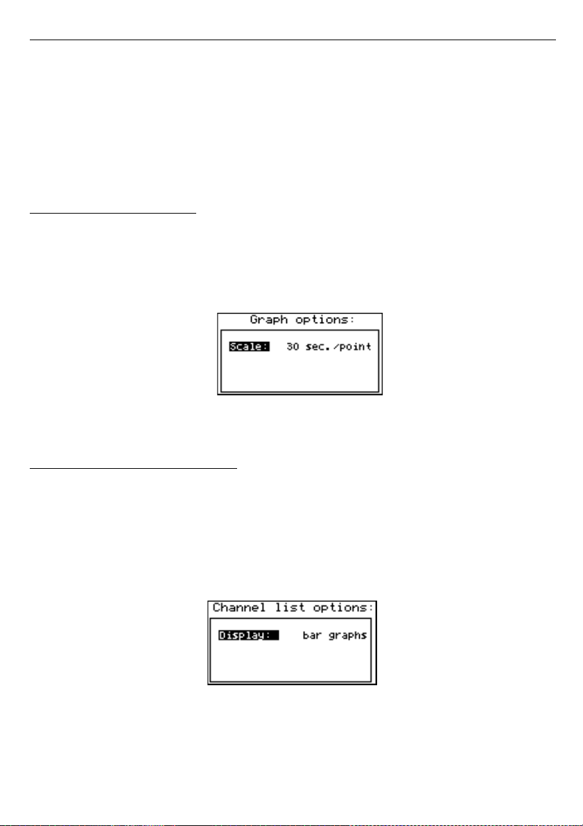
User manual - DATA RECORDER SRD-99 and cooperating software
”Date”,”Time”
- these options are available when the "
List type
" parameter was set as
"
historic
" and define the position of the horizontal line (located in the lower
part of the display) in relation to the recorded measurements results
displayed on the list. Above the horizontal line the display shows the results
of the measurement recorded before the time defined by "
Date
" and "
Time
"
parameters. Below the horizontal line display shows the result of the
measurement at the time (or directly after it) defined by "
Date
" and "
Time
"
parameters. The default values "
Date
" and "
Time
" parameters are the time
and date when the unit was switched on last.
7.2.2. ”Graph options” menu
This menu contains options configuring the method of displaying measurement results for
the "
Graph
" mode:
”Scale”
- this option allows time points corresponding to particular points on the horizontal
axis of the graph (time axis) to be defined. 16 options are available:
from
0.125 seconds/point
to
1 hour/point
.
Fig. 7.11. “Graph options” menu
7.2.3. ”Channels list options” menu
This menu contains options configuring the method of displaying measurement results for
the "
Channels list
" mode:
”Display”
- this option enables the selection of the method of displaying measurement
results. The following possibilities are available:
”values”
- measurement results displayed in numeric form
”bar graphs”
- measurement results displayed in the form of bars (percentage)
Fig. 7.12. "Channels list options" menu
43
Page 44
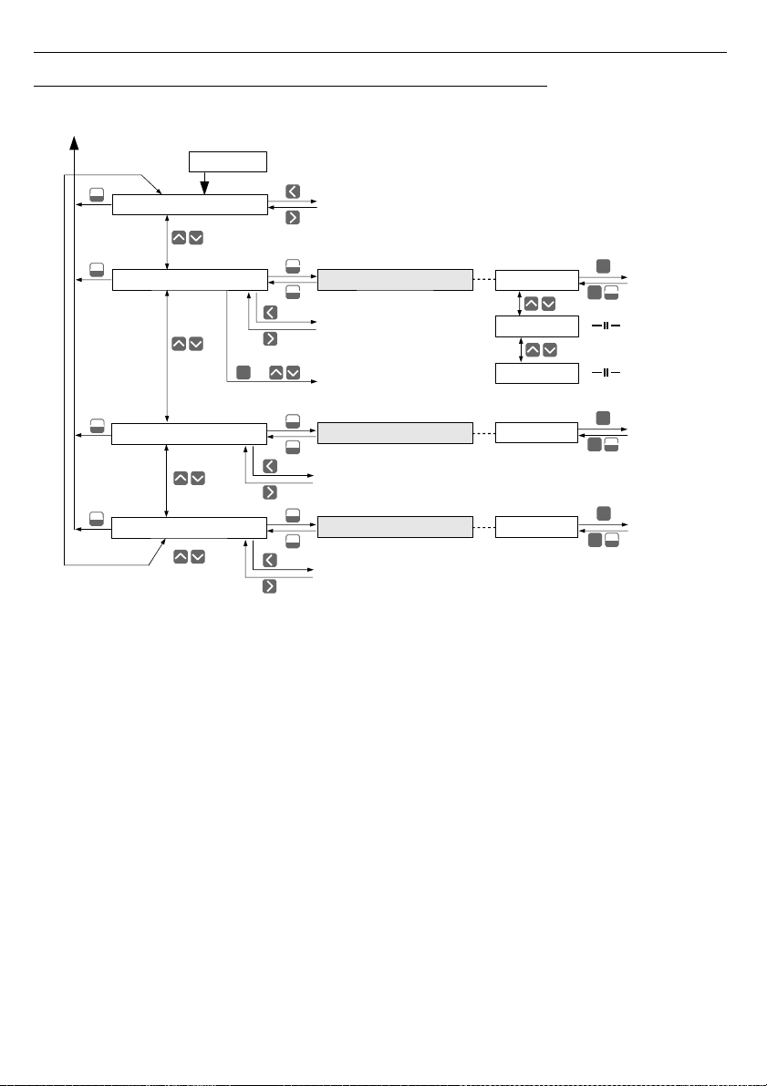
User manual - DATA RECORDER SRD-99 and cooperating software
7.3. RESULTS PRESENTATION MODES MENU STRUCTURE
44
Initialization
Power on
* Press and hold at least 2 seconds
Channels list options
Main menu
Channel selection
ENTER
MENU
ESC
ENTER
Display
Parameter
edition
Mode: ”Channels list”
Mode: ”Single channel”
MENU
ESC
*
MENU
ESC
MENU
ESC
Measurements list options
Date
MENU
ESC
*
Graph options
Scale
Mode: ”Graph”
MENU
ESC
MENU
ESC
ENTER
MENU
ESC
ENTER
Parameter
edition
ENTER
MENU
ESC
ENTER
Parameter
edition
+
Channel selection
MENU
ESC
*
Mode: ”Measurements list”
MENU
ESC
*
MENU
ESC
MENU
ESC
ENTER
List scrolling
Time
List type
Channel selection
Channel selection
Page 45
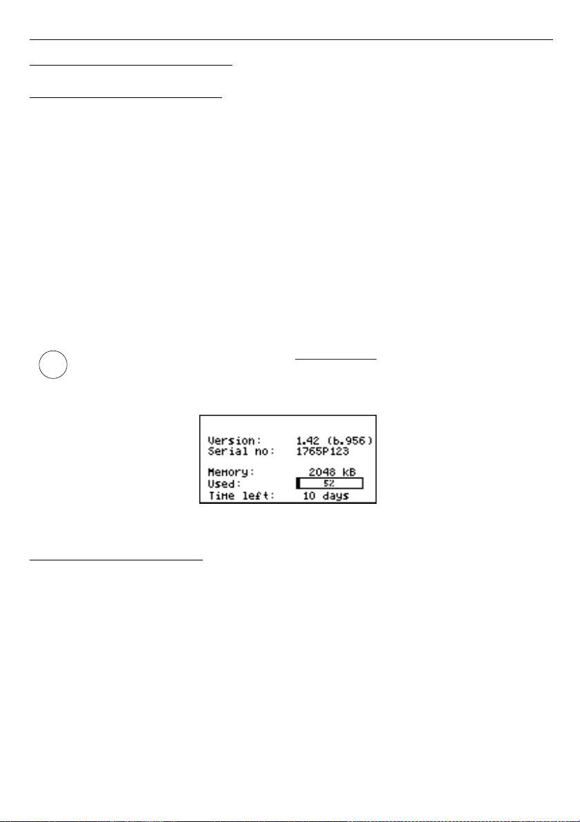
User manual - DATA RECORDER SRD-99 and cooperating software
7.4. MAIN MENU DESCRIPTION
7.4.1. ”Device information” menu
This menu contains information about the unit and cannot be edited:
”Version”
- version of unit firmware,
”Serial no”
- unit serial number,
”Memory”
- unit's memory size,
”Used”
- size of used memory,
”Time left”
- time remaining until memory will be filled with recorded values, established
on the basis of the currently set recording period and the number of recorded
channels. In the case of controlling the recording process using the digital
input, the value shown relates to the time, during which the voltage level on the
digital input allows the recording of measurements. If no measurement
channels are active the “
Logging disabled
” message is displayed.
Once the memory is filled with recorded measurement results, the
“
Data overwriting
” or “
Logging stopped
” message is displayed (depending
on the set value of the "
Write
" parameter in the "
Logging setup
" menu).
The calculated "
Time left
" time is an
approximated
value. Download the recorded
data to your PC before this time expires. The data downloaded to a PC remain in the
unit's memory, but is not taken into consideration when the "
Time left
" parameter is
established and can be deleted without warning at any moment.
Fig. 7.13. "Device information" menu
7.4.2. ”Display options” menu
This menu contains options that enable the displaying parameters of the LCD to be
changed:
”Backlight”
- this option allows one to define when the LCD backlight is to be switched on.
The following possibilities are available:
”permanent”
- backlight always On,
”temporary”
- backlight is turned on when any key on the unit is pressed and
switches Off after 1 minute since the last activation of the keys,
and turned on for approximately 10 seconds when the unit is
switched on.
”Brightness”
- brightness of display backlight as a percentage
”Contrast”
- contrast of the display as a percentage
45
i
Page 46
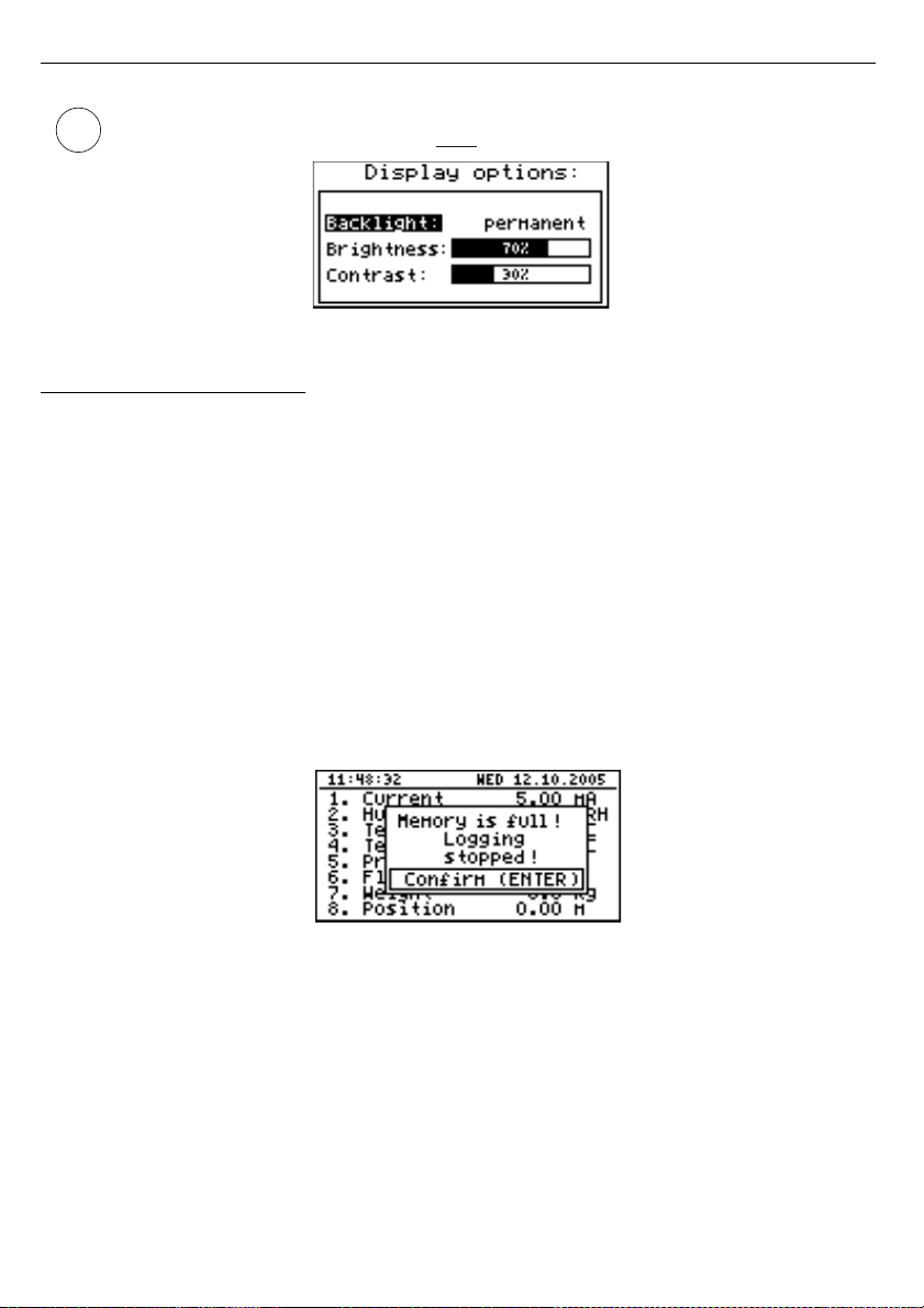
User manual - DATA RECORDER SRD-99 and cooperating software
If the display backlight is inactive and the “
Backlight
” option was set as
“
temporary
” pressing any key will
only
switch the backlight on.
Fig. 7.14. ”Display options”
menu
7.4.3. ”Logging setup” menu
This menu contains options defining the recording method and recorded channels:
”Write”
- this option defines the behaviour of the unit after writing all available memory with
the recorded measurement results. The following options are available:
”until full”
- once the entire available memory is filled with recorded measurement
results the recording will be stopped and a warning message (
Fig. 7.15
)
shall be displayed; this warning message must be confirmed with the
[
ENTER
] key.
This warning shall be repeated when the unit is switched on. Instead of
“
Time left
” parameter in the "
Device information
” menu the display will
show the “
Logging stopped
” message. The recording will be restarted
only when the collected measurement results are downloaded to a PC
(once unit's memory is free).
If the collected measurement results will be downloaded to a PC before
memory is full, the warning message will not be displayed.
Fig. 7.15. Warning in “until full” recording mode
”cyclic”
- after filling all the available memory with recorded measurement results, the
measurement results recorded next will be written from the starting address in
the memory, overwriting previously recorded data. During the first overwriting
operation a warning message (
Fig. 7.16
) will be displayed; this message must
be confirmed with the [
ENTER
] key. This warning shall be repeated when the
unit is switched on. Instead of “
Time left
” parameter in the
"
Device information
” menu the display will show the “
Data overwriting
”
message.
If the collected measurement results will be downloaded to a PC before
memory is full, the warning message will not be displayed.
46
i
Page 47
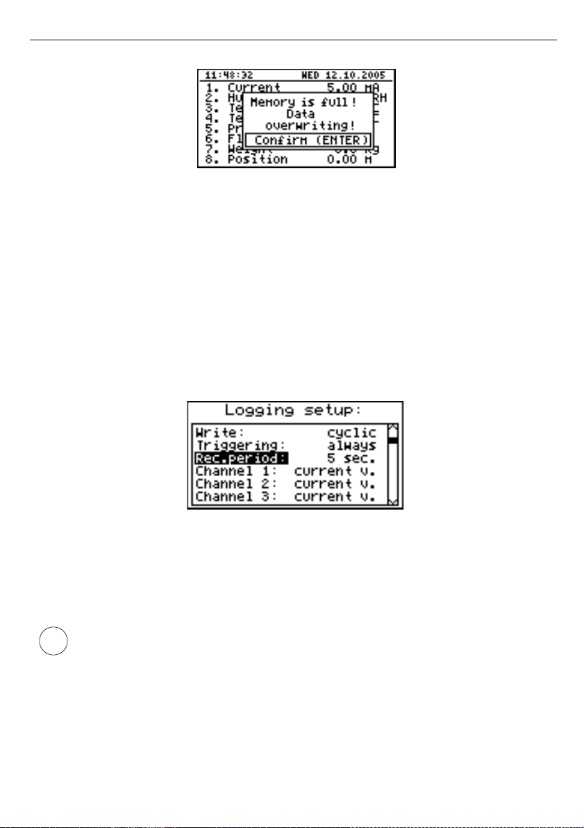
User manual - DATA RECORDER SRD-99 and cooperating software
Fig. 7.16. Warning in “cyclic” recording mode
”Triggering”
- method of recording measurement results. The following options are
available:
”always”
- measurements are recorded in time intervals defined by the
“
Recording period
”
parameter,
”high level”
- measurements are recorded in time intervals defined by the
“
Recording period
”
parameter, only when the voltage of digital input
is 24V,
”low level”
- measurements are recorded in time intervals defined by the
“
Recording period
”
parameter, only when the voltage of digital input
is 0V.
Fig. 7.17. “Logging setup” menu
”Rec.period”
- this parameter defines the interval for measurement recording. 15 options are
available:
1 sec./ 2 sec. / 5 sec. / 10 sec. / 15 sec. / 20 sec. / 30 sec. /
1 min. / 2 min. / 5 min. / 10 min. / 15 min. / 20 min. / 30 min. / 60 min.
Measurements are synchronized with the unit’s internal real time clock, therefore
when the “
Recording period
” parameter is set, for example, for 5 seconds the
measurements will be executed for the fifth, tenth, fifteenth (etc.) second of each
minute. If parameter ”
Rec. period
” is set to value lower than sampling period (2.5s
for RTD version), then the same measurements will be logged many times.
”Channel 1”
...
”Channel 8”
- these options allow the type of value recorded in unit’s
memory to be defined (the number of measurement channels
available on the list depends on the unit version).
The following values are available:
47
i
Page 48
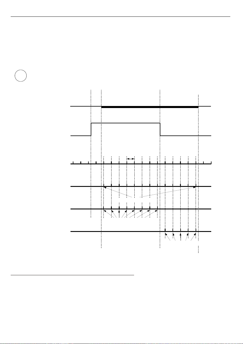
User manual - DATA RECORDER SRD-99 and cooperating software
”disabled”
- data from the selected measurement channel will not be recorded,
”current v.”
- current values (corresponding to the results of current measurements)
will be recorded for the selected measurement channel,
”average v.”
- averaged values will be recorded for the selected measurement channel
(see section
MEASUREMENT MODE
, point
6.1.5
).
If the
“Input type”
in the
“Inputs settings”
menu shall be set as
“disabled”
for a
given channel, then this channel will not be available on the list of recording
channels in the
“Logging setup”
menu.
Fig. 7.18.
Recording points depending on “Triggering” parameter value.
7.4.4. “Temperature unit” parameter (RTD version)
This parameter allows to change unit in which the measurements are made. Available
scales are Celsius and Fahrenheit.
48
i
„disabled“
„disabled“
„current v.“ or „average v.“
low (0V)
high (24V)
low (0V)
”Rec.period”
parameter
registered measurements
registered measurements
registered measurements
. . .
”Channel 1”...”Channel 8”
parameters settings
Didital input state
All possible points of data
registration synchronized to
internal clock
Points of data registration
for option
”Triggering”=”Always”
Points of data registration
for option
”Triggering”=”hi level”
Points of data registration
for option
”Triggering”=”lo level”
Page 49
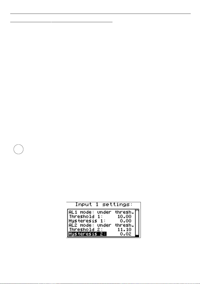
User manual - DATA RECORDER SRD-99 and cooperating software
7.4.5. ” Input settings ” menu (common parameters)
This menu enables the configuring of current inputs. The number of the configured input
is displayed in the upper part of the display (
Fig. 7.19
).
The following options are available in this menu:
”Name”
- name assigned for the given channel (9-character sequence enabling identification
of given channel),
”Filter”
- this option enables the level of the filtration of indications to be changed.
Permissible values: from 0 (no filtration) to 5 (filtration with maximum time constant
of approx. 2 seconds).
”
AL1 mode
”
”
AL2 mode
”
- those parameters describes the way of alarms generation. Each channel is
able to generate two independent alarms, used in control of the outputs (see
„
Outputs settings
”). The following options are available:
”
Under threshold
”
- alarm is generated when displayed value in this channel is
under entered value.
”
Over threshold
”
- alarm is generated when displayed value in this channel is
over entered value.
”
Threshold 1
”
”
Threshold 2
”
- the value entered in this field is constantly compared with the current
value. Outpassing this value (up or down, depends on mode setting)
causes alarm generation.
Entered values are not checked by the device. If value of the threshold is out range
of the current channel (e.g.: -10 when minimal value in the channel is 0) specific
alarm will not be generated (or will be generated continuously, depending on
„
AL1 mode
”, „
AL2 mode
” settings).
”
Hysteresis 1
”
”
Hysteresis 2
”
- the hysteresis values for the ”
Threshold 1
” and ”
Threshold 2
”
parameters. Those parameters can be configured to prevent generation of
short and often alarms. When this parameter is set to value greater than 0
the specific alarm is generated when displayed value exceeds threshold
+/- hysteresis.
Fig. 7.19. „Input settings” - alarms settings
49
i
Page 50

User manual - DATA RECORDER SRD-99 and cooperating software
7.4.6.
”Input settings” menu (
I version )
”Unit”
- 4-character sequence constituting the unit for the value measured on the given
channel.
Fig. 7.20. ”Inputs settings”
(part 1)
”Input type”
- type of input/sensor. The following options are available:
”inactive”
- input is not active
”0-20 mA”, ”4-20 mA”
- current inputs, displayed value is defined by “
Hi value
”,
“
Lo value
” and "
Dec. point
" parameters.
”Hi value”
”Lo value”
- these parameters define the values displayed for maximum (Hi), and
minimum (Lo) current of
user defined range
(0-20 mA or 4-20 mA). The
aforesaid parameters can be set in the range - 9999 ÷ 9999.
A negative number can be input by entering a
'–'
mark (using
[^], [v]
keys).
The value of the
“Lo value”
parameter can be higher than the value of
“Hi value”
parameter. In such a case, for an increasing value of input current the displayed
value decreases.
Fig. 7.21. ”Inputs settings” menu
(part 2)
”Dec. point”
- position of the decimal point for results displayed in numerical form.
The following options are available:
” 0”
” 0.0”
” 0.00”
”0.000”
The position of the decimal point is selected with
[^], [v]
keys.
50
i
Page 51
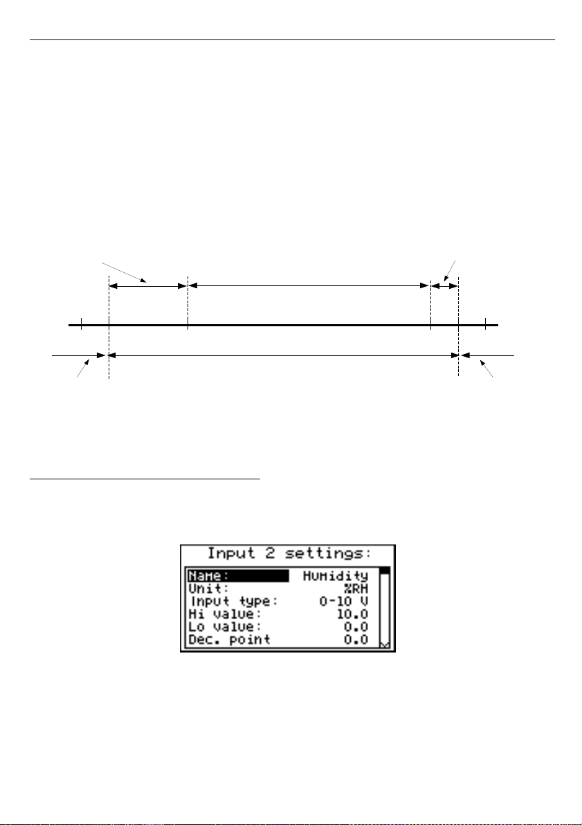
User manual - DATA RECORDER SRD-99 and cooperating software
”Upper ext.”
”Lower ext.”
- parameter defining the allowable range of input currents (
Fig. 7.20
).
If the input current lies within the defined range then the appropriate
measurement result shall be displayed despite exceeding the nominal
measurement value 0-20 mA or 4-20 mA. If the input current exceeds the
range defined by
“Upper extension”, “Lower extension”,
a "-Hi-" or "-Lo-"
message (depending on the direction of exceeding the range) shall be
displayed instead of the measurement result in numeric form. The
“Upper
extension”
and
“Lower extension”
values are defined in mA with the
accuracy of 0.01 mA. The
“Lower extension”
value is defined in relation to
a 4 mA current, in the range of 0-3.99 mA (this parameter is significant only
in the "4-20 mA" mode). The
“Upper extension”
value is defined in relation
to a 20 mA current in the range of 0-1.99 mA.
Fig. 7.22. Defining permissible measurement range for an example of settings of
“Upper ext.” and “Lower ext.” parameters (for user range 4-20 mA)
7.4.7.
”Input settings” menu (
U version )
”Unit”
- 4-character sequence constituting the unit for the value measured on the given
channel.
Fig. 7.23. ”Inputs settings”
(part 1)
”Input type”
- type of input/sensor. The following options are available:
”inactive”
- input is not active
”0-5 V”, ”1-5 V”;
- current inputs, displayed value is defined by “
Hi value
”,
”0-10 V”, ”2-10 V”
“
Lo value
” and "
Dec. point
" parameters.
51
user defined range (4-20 mA)
permissible measurement range
”Lower ext.” = 3mA
”Upper ext.” = 1 mA
measurement result is displayed
regardless on nominal range exceeding
display
message ”-Lo-”
4
display
message ”-Hi-”
10 20 21 22
Page 52
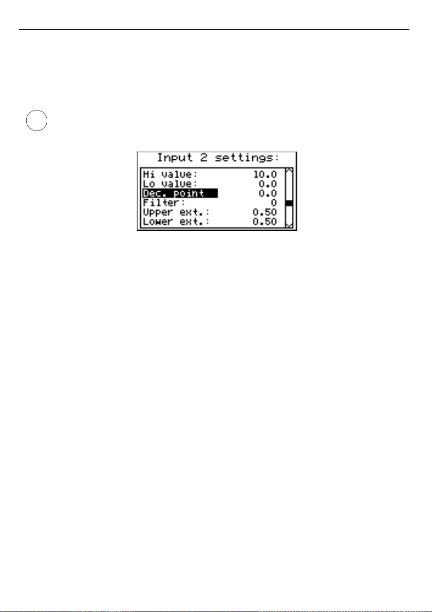
User manual - DATA RECORDER SRD-99 and cooperating software
”Hi value”
”Lo value”
- these parameters define the values displayed for maximum (Hi), and
minimum (Lo) voltage of
user defined range
(0-5 V, 1-5 V, 0-10 V or
2-10 V). The aforesaid parameters can be set in the range - 9999 ÷ 9999.
A negative number can be input by entering a
'–'
mark (using
[^], [v]
keys).
The value of the
“Lo value”
parameter can be higher than the value of
“Hi value”
parameter. In such a case, for an increasing value of input current the displayed
value decreases.
Fig. 7.24. ”Inputs settings” menu
(part 2)
”Dec. point”
- position of the decimal point for results displayed in numerical form.
The following options are available:
” 0”
” 0.0”
” 0.00”
”0.000”
The position of the decimal point is selected with
[^], [v]
keys.
”Upper ext.”
”Lower ext.”
- parameter defining the allowable range of input voltages (
Fig. 7.21
).
If the input voltage lies within the defined range then the appropriate
measurement result shall be displayed despite exceeding the nominal
measurement value 0-5 V, 1-5 V, 0-10 V or 2-10 V. If the input voltage
exceeds the range defined by
“Upper extension”, “Lower extension”,
a
"-Hi-" or "-Lo-" message (depending on the direction of exceeding the range)
shall be displayed instead of the measurement result in numeric form. The
“Upper extension”
and
“Lower extension”
values are defined in V with
the accuracy of 0.01 V. The
“Lower extension”
value is defined in relation
to a 1 V in the range of 0-1.99 V or 2 V voltage in the range of 0-0.99 V (this
parameter is significant only in the "1-5 V" and “2-10 V” mode). The
“Upper
extension”
value is defined in relation to a 10 V voltage in the range of
0-1.99 V.
52
i
Page 53
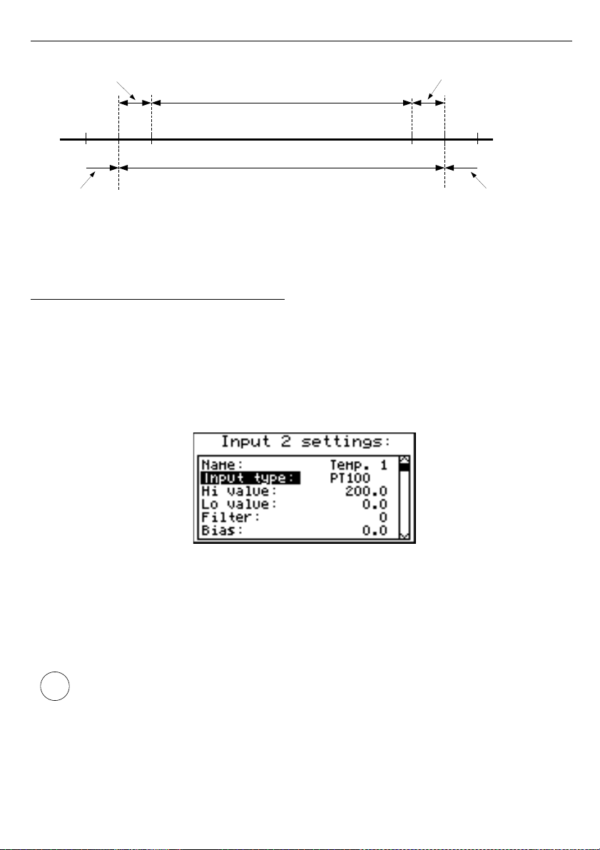
User manual - DATA RECORDER SRD-99 and cooperating software
Fig. 7.25. Defining permissible measurement range for an example of settings of
“Upper ext.” and “Lower ext.” parameters (for user range 2-10 V)
7.4.8.
”Input settings” menu (
RTD version )
”Input type”
- type of input/sensor. The following options are available:
”inactive”
- input is not active
”PT100”
”PT500”
”PT1000”
- temperature sensor inputs,
user defined range
is defined
by “
Hi value
”and “
Lo value
” parameters.
Fig. 7.26. ”Inputs settings”
”Hi value”
”Lo value”
- These parameters define lower and upper limits of
user defined range
.
The percentage results, and the graph are scaled due to this range. The
aforesaid parameters can be set in the range -999.9 ÷ 999.9. A negative
number can be input by entering a
'–'
mark (using
[^], [v]
keys).
The value of the
“Lo value”
parameter can be higher than the value of
“Hi value”
parameter. In such a case, the device automatically selects lower value as lower
limit, and higher value as upper limit of
user defined range
.
”Bias”
- offset (expressed in 0.1°C, range ± 9.9°C (or ±9,9°F)). This parameter allows
shifting of measurement scale, and express value added to calculated (measured)
result.
53
i
user defined range (2-10 V)
permissible measurement range
”Lower ext.” = 1 V
”Upper ext.” = 1 V
measurement result is displayed regardless on
nominal range exceeding
display
message ”-Lo-”
2
display
message ”-Hi-”
10 10 11 12
Page 54

User manual - DATA RECORDER SRD-99 and cooperating software
7.4.9. ” Outputs settings ” menu
This menu allows to change settings of the outputs.
”
Mode
” - Defines operation mode of the output. The following options are available:
”
inactive
” - output is always OPEN. State of the attached channels alarms are
ignored,
”
N.O.
” - normally OPEN,
”
N.C.
” - normally CLOSED.
”
Logic funct.
” - describes active-state computing method for attached alarms. The
following options are available:
„OR” - output is active when
any
of the attached channels is alarm state.
„
AND
” - output is active when
all
of the attached channels are in alarm state.
”
Source
” - brings up a submenu with alarm sources settings (
Fig. 7.27
). The following options
are available for each channel:
”
inactive
” - channel is ignored (never in alarm state).
”
alarm 1
” - channel is in alarm state when alarm 1 is generated.
”
alarm 2"
- channel is in alarm state when alarm 2 is generated.
”
alarm 1 or 2
” - channel is in alarm state when alarm 1 or alarm 2 are generated.
”
alarm 1 and 2
” - channel is in alarm state when alarm 1 and alarm 2 are generated
in the same time.
Fig. 7.27. Submenu ” Source” in menu „Outputs settings”.
”
Close delay
” - Output switch from open to closed state will be delayed until this time elapse.
”
Open delay
” - Output switch from closed to open state will be delayed until this time elapse.
If condition to switch state of the output will repeat occurring more often than half of
the delay and mean duty cycle (D) will be greater than 50% the output will
eventually switch. See chapter ”
Outputs control
” for more details.
”
Closed hold time
” - a relay active state maintain time after the triggering signal disappears,
”
Open hold time
” - a relay inactive state maintain time after the triggering signal disappears,
54
i
Page 55
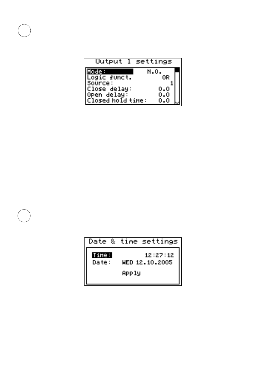
User manual - DATA RECORDER SRD-99 and cooperating software
• All time type parameters which describe outputs, can be set in range 0 ÷ 9999
with resolution of 1 sec.
• Because of computing precision, the time is shorter about 2.5% than the entered
value. This means if time is set to 100.0s the real time will be shorter about 2.5s.
Fig. 7.28. ” Outputs settings” menu.
7.4.10. ”Date & time settings” menu
Menu allows to change date and time of internal clock (RTC):
”Time”
- current time according to the unit’s real time clock,
”Date”
- current date according to the unit’s real time clock,
”Apply”
- this option enables the internal real time clock to be set according to values of the
“
Time
” and “
Date
” parameters.
After entering the menu the current indications of the internal clock are displayed. The
changing of parameters (
“Time”
or
“Date”
) stops the indications updating. Changed
parameters must be stored using the
“Apply”
option.
Reversing the Data Logger unit’s clock (date and time) shall delete all data recorded
by the unit, the recording time of which was later than the new time. In order not to
lose the recorded data, it must be downloaded to a PC before the clock is reversed.
Fig. 7.29. ”Date & time settings” menu
55
i
i
Page 56
User manual - DATA RECORDER SRD-99 and cooperating software
7.4.11. ”RS485 port settings” menu
This menu contains options to configure the RS-485 interface:
”Address”
- this parameter specifies the unit’s address, according to the Modbus protocol
(in the range of 0 to 99). If the address is set as 0, then the unit responds to
the FFh address.
”Baud rate”
- this option defines the RS-485 serial interface transmission speed.
8 possibilities are available:
”
1200
”, ”
2400
”,”
4800”, ”9600
”, ”
19200”, ”38400
”, ”
57600
”, ”
115200
” b/sec.
Default baud rate value is 115200 b/sec. Some RS-485 converters may not work
properly with this setting. In such a case set lower baud rate (according to converter
data sheet).
”Resp. delay”
- this parameter defines minimal (additional) delay between the Modbus
message and the answer of the device (received and sent via RS-485
interface). This additional delay allows the device to work with poor RSconverters which do not works properly on baud rates higher than 19200. This
parameter can be set to one of values:
”stand.”
- device responds without any additional delay
”+10 ch.”
”+20 ch.”
”+50 ch.”
”+100 ch.”
”+200 ch.”
The unit response with additional delay equal to
transmission time of 10, 20, 50, 100 or 200 characters.
In the most cases parameter
”Response delay”
should be set to
”Stand.”
(no
additional delay). Unfortunately for some third party RS-converters
”Response delay”
should be adjusted experimentally. Table below contains most
frequently used values.
”Baud rate” parameter
“38400” “57600” “115200”
”Resp. delay” parameter
“+10 ch.” “+20 ch.” “+50 ch.”
Tab. 7.1. Settings of ”Resp. delay” parameter
”Conf. change”
- this option allows the method of accessing unit’s configuration registers
through the RS-485 interface to be defined.
The following options are available:
”denied”
- configuration registers can not be set via RS-485 interface,
”allowed”
- configuration registers can be set via RS-485 interface.
56
i
i
Page 57
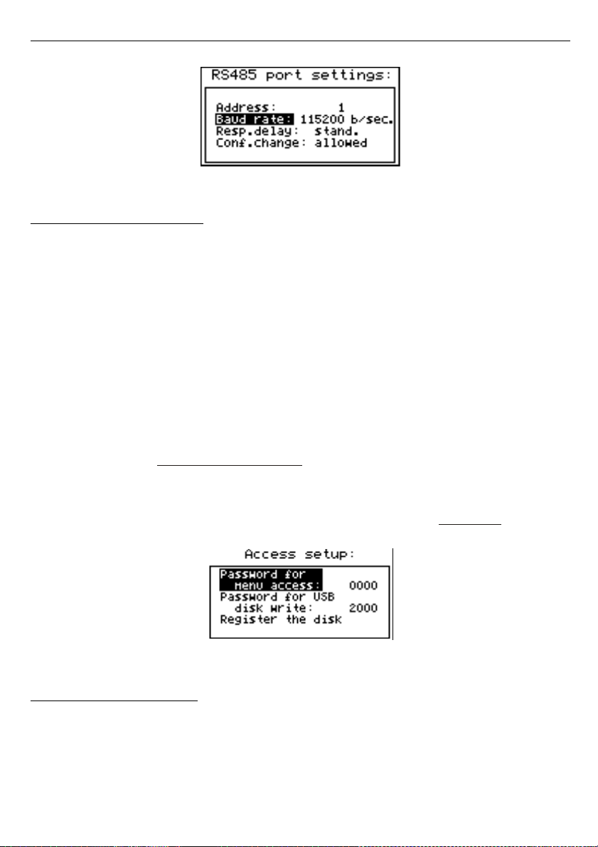
User manual - DATA RECORDER SRD-99 and cooperating software
Fig. 7.30. “RS485 port settings” menu
7.4.12. ”Access setup” menu
This menu contains options controlling access to the unit’s adjustable parameters and to
data downloading function (using USB Host port):
”Password for menu access”
- menu access password (4-digit number). If the parameter is
set to “
0000
” the password is disabled. If the parameter is different from
“
0000
” then menu access requires password to be entered.
If the user do not remember his password, the access to the menu is possible by the
“one-
use password”
. To get this password please contact with Marketing Division. Please set new
user password immediately after use of the
“one-use password”
.
”Password for USB disk write”
- password for data downloading to the flash disk (4-digit
number). If the parameter is set to “
0000
” the password is disabled. If
the parameter is different from “
0000
” then data downloading to
unregistered flash disk
- PenDrive requires password to be entered
(registering can be done using
”Register the disk”
option).
”Register the disk”
- this function allows registering (unregistering) single USB type
FlashDrive (PenDrive). Data can be stored on
registered
flash drive
without entering of the password.
Fig. 7.31. “Access setup” menu
7.4.13. ”USB options” menu
This menu contains options which allows copying of device configurations between PC
and data logger unit, and automatic data transfer using USB type FlashDrive (PenDrive):
”Write config. to disk”
- this option allows writing device configuration to FlashDrive.
”Read config. from disk”
- this option allows reading device configuration from FlashDrive.
57
Page 58
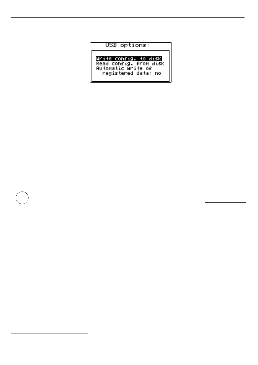
User manual - DATA RECORDER SRD-99 and cooperating software
After selection one of options above device waits for plugging in of FlashDrive. If disk is
found then device displays the message which allows approving or cancelling selected
operation.
Fig. 7.32. “USB options” menu
To return to
”USB options”
menu, after finished reading or writing of configuration,
FlashDrive should be unplugged or any key pressed.
If error occurs while reading or writing proper message is displayed. User have to confirm
this message using
[ENTER]
.
”Automatic write of registered data”
- this option allows activating of automatic data
storage to the Flash Drive plugged to USB socket.
Automatic data writing is made periodically, after recording about 70 kB of new data,
what keeps the usage of internal memory below about 1%.
Autostorage frequency depends on recording settings (number of channels, and
recording period). Minimum period between successive data storages is about 50 min. (8
channels recorded every 1 sec.).
• In case of error while auto data writing, device displays a proper message and
waits for user acknowledge. While waiting for acknowledge,
DEVICE DOES
NOT EXECUTE ANY AUTOSTORAGES
, but all data is recorded to internal
memory of the device. Due to the possibility of occurrence of: write error,
FlashDrive or USB malfunction, and other incidental problems, autostorage
function should be controlled by user from time to time. Lack of control can
cause overwriting of data in internal memory or stopping of data recording due
to impossibility of data storage on FlashDrive.
• If “
Password for USB disk write
” parameter has been set, then after power
off / on sequence it is necessary to enter this password to run “Auto data write”
function. To omit this requirement it is recommended to use function “
Register
the disk
” or disable of “
Password for USB disk write
”.
• While “Auto data write” is active and FlashDisk is plugged to USB connector,
pressing the
[ENTER]
key in any presentation mode will force the storage of
current data to the Flash Drive (other functions of
[ENTER]
key are disabled).
To allow default functions of
[ENTER]
button, it is necessary to unplug Flash
Drive from USB connector.
• Depending on the recording settings, periods between successive storages can
be long. To be sure that current data (up to now) had been written, force data
storage (pressing
[ENTER]
in any data presentation mode) before disconnecting
the Flash Drive from USB (see the previous note).
7.4.14. ” Language ” parameter
This parameter allows selection of messages and menu language.
58
i
Page 59

User manual - DATA RECORDER SRD-99 and cooperating software
7.5. MAIN MENU STRUCTURE
59
0 _ _ _
4-digit user password entering (if it is different from „0000”)
Press and hold at least 2 seconds
MENU
ESC
ENTER
Logging setup
MENU
ESC
MENU
ESC
MENU
ESC
Device information
Result presentation mode
Input type
Parameters
viewing
ENTER
MENU
ESC
ENTER
ENTER
MENU
ESC
ENTER
ENTER
Backlight
Brightness
Contrast
Parameter
edition
Lo value
Filter
Hi value
Upper ext.
Lower ext.
Dec.point
MENU
ESC
Inputs settings
ENTER
MENU
ESC
ENTER
MENU
ESC
Name
Unit
Parameter
edition
Rec.period
Channel 8
Triggering
ENTER
ENTER
MENU
ESC
ENTER
Write
Display options
MENU
ESC
Channel 1
Channel 2 ... Channel 7
MENU
ESC
ENTER
Parameter
edition
MENU
ESC
AL1 mode
Threshold 1
Hysteresis 1
AL2 mode
Threshold 2
Hysteresis 2
See next page
Notice:
Parameters „Unit”, “Dec. point”,
“Upper ext.” and „Lower ext.”
are available for current and voltage
inputs only, parameter „Bias”
is available for RTD inputs only.
Bias
MENU
ESC
Temperature unit
ENTER
MENU
ESC
ENTER
Parameter
edition
Page 60
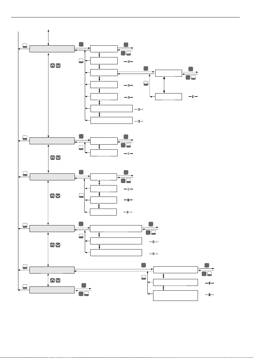
User manual - DATA RECORDER SRD-99 and cooperating software
60
MENU
ESC
Date & Time settings
ENTER
MENU
ESC
ENTER
ENTER
Time
Date
Parameter
edition
MENU
ESC
RS485 port settings
MENU
ESC
Resp.delay
Conf.change
Baud rate
ENTER
ENTER
MENU
ESC
ENTER
Address
Parameter
edition
MENU
ESC
Password for USB disk write
MENU
ESC
Language
ENTER
MENU
ESC
ENTER
Parameter
edition
MENU
ESC
MENU
ESC
Access setup
ENTER
ENTER
MENU
ESC
ENTER
Password for menu access
Parameter
edition
Register the disk
Read config. from disk
MENU
ESC
MENU
ESC
USB options
ENTER
ENTER
MENU
ESC
ENTER
Write config. to disk
Parameter
edition
Automatic write of
registered data
MENU
ESC
Output settings
ENTER
MENU
ESC
ENTER
ENTER
Mode
Logic funct.
Parameter
edition
MENU
ESC
Source
Close delay
Open delay
Closed hold time delay
Open hold time delay
Channel 8
Channel 1
Channel 2 ... Channel 7
MENU
ESC
ENTER
See previous page
ENTER
MENU
ESC
ENTER
Parameter
edition
Page 61
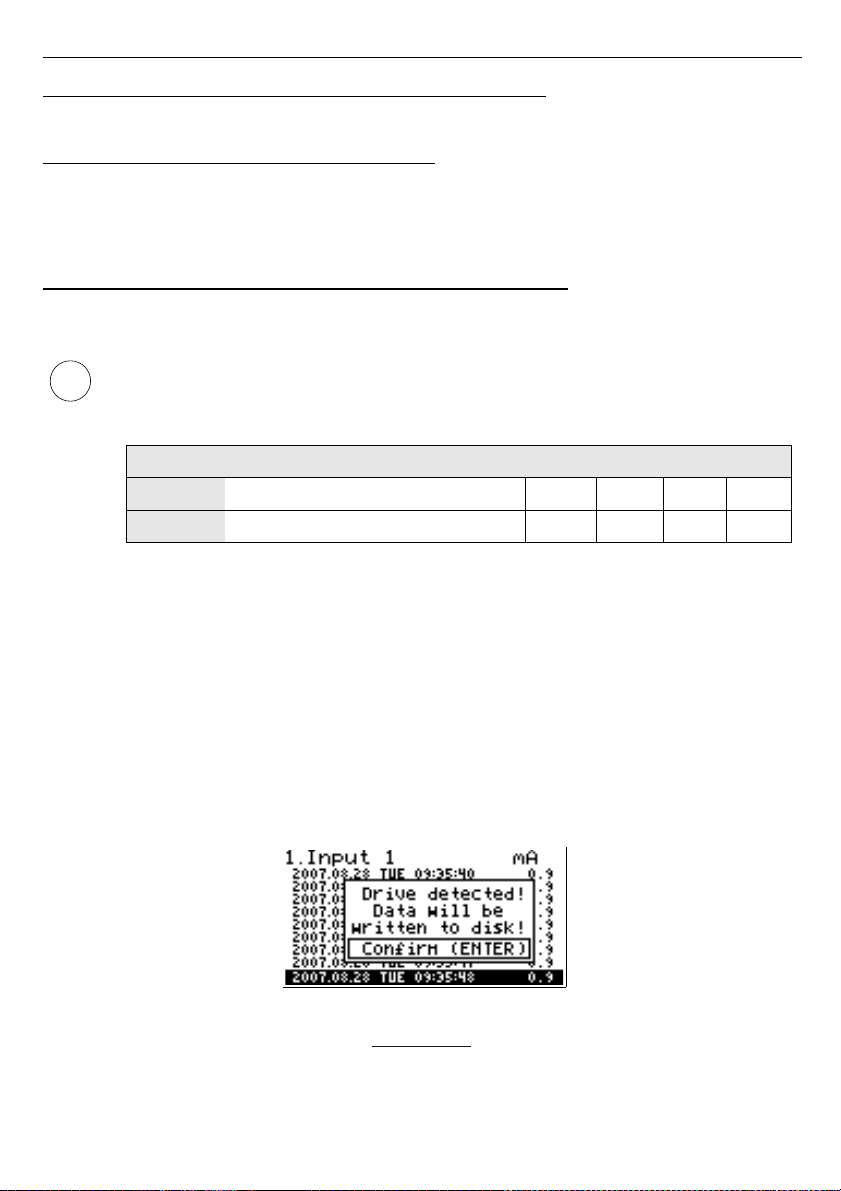
User manual - DATA RECORDER SRD-99 and cooperating software
8. DOWNLOADING DATA FROM DATA LOGGER
8.1. MODBUS (RS485) DATA DOWNLOAD
To download data form the data logger connect it to PC via USB/RS-485 or RS-232/RS-
485 serial converter and use
Loggy Soft
delivered with the device. Description of
Loggy
Soft
can be found in further chapter of this manual.
8.2. USB FLASH DRIVE (PENDRIVE) DATA DOWNLOAD
If data logger is equipped with USB Host interface, then the stored data can be
downloaded from the data logger without PC connection.
1.
Before using a FlashDrive, format it in Windows system to FAT or FAT32 file
system. During formatting operation set the parameters according to the
table below.
format
FAT FAT32
size
1GB 2GB 1GB 2GB 4GB 8GB 16GB
cluster
default default default 8KB 16KB 32KB 64KB
Tab. 8.1. Allowable FlashDrive formatting
Example of FlashDrive
8GB
formatting (FlashDrive available as disk drive P):
format P: /A:32k
2.
If data logger errors occur during read / write operation using FlashDrive,
format it as shown in notice 1.
3.
For FlashDrive grater than 16GB, proper read / write operations are not
guaranteed.
To get data from
Data Logger
device plug a FlashDrive to USB Host port, located on the front
panel of the device.
The following message will appear after a few seconds:
User can confirm (
[ENTER]
key) to start data downloading, or cancel the download
(
[ESC/MENU]
key). FlashDrive device
MUST NOT
be removed during data downloading.
Unexpected removal can cause a data corruption on the FlashDrive device.
Depending on the number of newly logged measurements, the data download time can vary
from a few seconds to three minutes. A progress bar is displayed during the data write:
61
i
Page 62
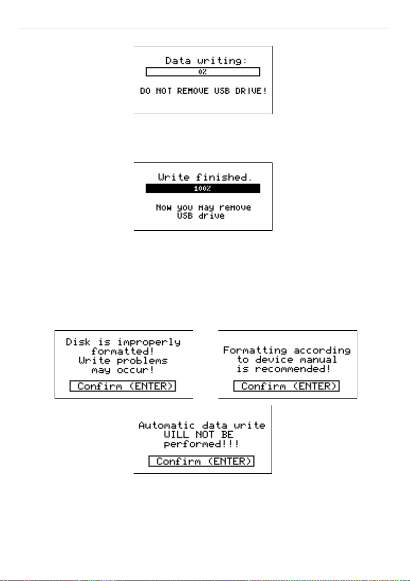
User manual - DATA RECORDER SRD-99 and cooperating software
After successful data write the following message will appear, which has to be confirmed
by pressing ENTER key:
In order to transfer logged data to the PC, connect FlashDrive to PC and use
Loggy Soft
.
Description of
Loggy Soft
can be found in further chapter of this manual.
In case of incorrect flash drive formatting, the user will be informed by one of following
messages:
1) When pendrive is formatted using default Windows standards and automatic write mode is
selected (file writing not done)
62
Page 63
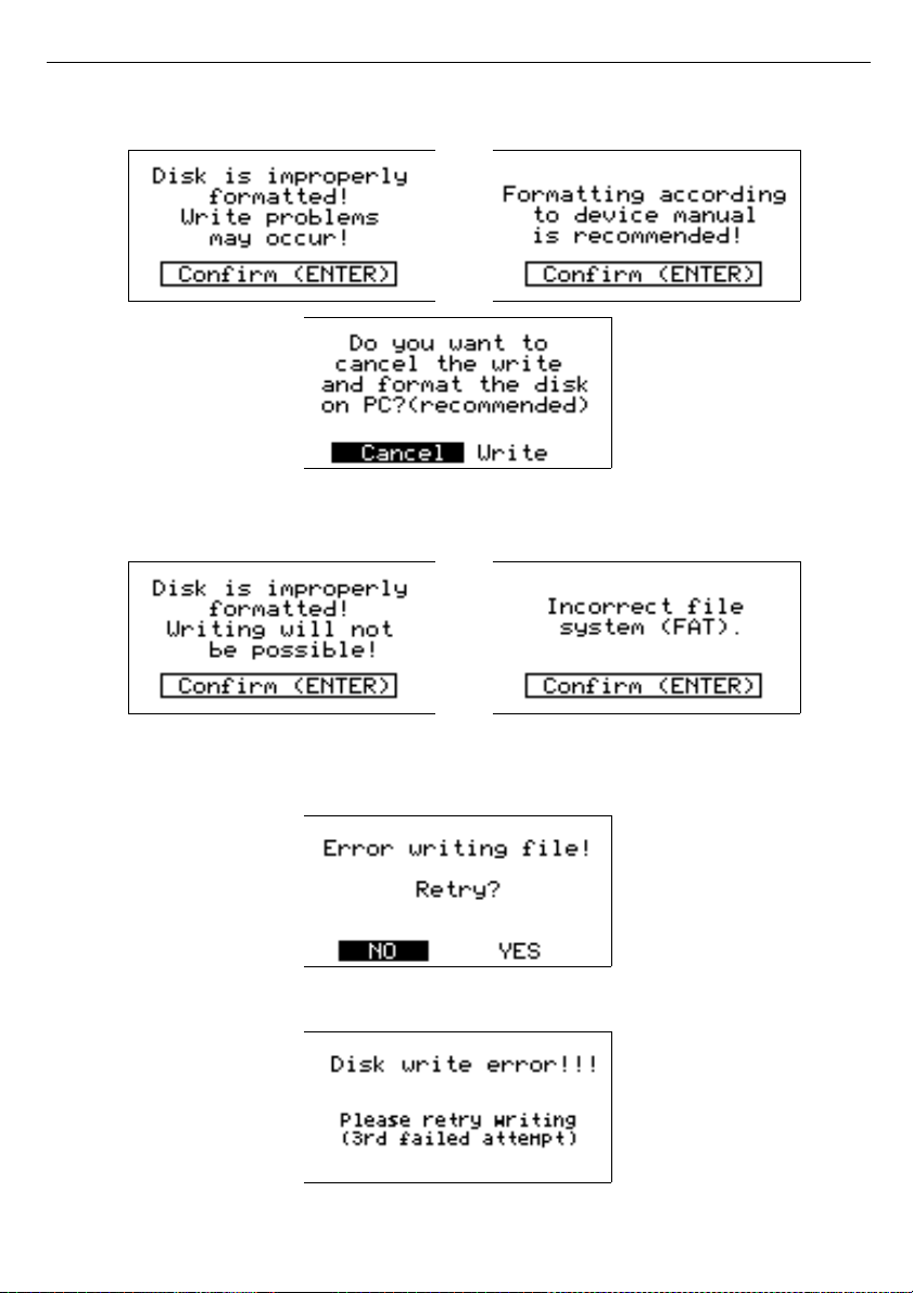
User manual - DATA RECORDER SRD-99 and cooperating software
2) When pendrive is formatted using default Windows standards and manual write mode is
selected (file writing can be forced but it may cause errors)
3) When pendrive is formatted not in accordance with
Tab. 8.1
(file writing not done)
If some error occurs during measurement writing, one of following messages will appear:
1) Write retrial question (when manual write mode is selected)
2) Third unsuccessful writing attempt message (when automatic write mode is selected)
63
Page 64

User manual - DATA RECORDER SRD-99 and cooperating software
9. THE MODBUS PRO TOCOL HANDLING
Transmission parameters: 1 start bit, 8 data bits, 1 stop bit, no parity control
Baud rate: selectable from: 1200 to 115200 bits/second
Transmission protocol: MODBUS RTU compatible
The device parameters and measurement result are available via RS-485 interface, as
HOLDING-type registers of Modbus RTU protocol. The registers (or groups of the registers)
can be read by 03h function, and wrote by 06h (single registers) or 10h (group of the registers)
accordingly to Modbus RTU specification.
9.1. LIST OF REGISTERS
Register Write Range Register description
01h
1
No see descr.
Measurement result for channel 1 (not considering the decimal point)
Current inputs version range: -9999÷9999
RTD inputs version range: -1000÷6000 (for °C)
-1480÷11120 (for °F)
Register from 02h1 to 08h
1
Measurement result for channel 2..8, registry description like for
channel 1 (see registers 01h).
09h No 0÷0FFFFh
Information about exceeding the allowable measurement range on the
given measurement channel in binary form:
HGFEDCBAhgfedcba
.
Higher(2nd) byte
- exceeding upper limit of measurement range
(H - channel no 8, A - channel no 1).
Lower(1st) byte
- exceeding
upper limit of measurement range (h - channel no 8,a - channel no 1).
1
- exceeding the range, 0 - measurement result within range
0Bh No 0÷3
Outputs state (binary)
00000000 000000ba
:
a
– output 1
b
- output 2
0
– open; 1 – closed
11h Yes 0÷1
"
Backlight
" parameter in "
Display options
" menu:
0
- permanent, 1 - temporary
12h Yes 0÷20 LCD backlight brightness
13h Yes 0÷20 LCD contrast
14h Yes 0÷3
"
Language
" parameter: 0 - Polish, 1 - English, 2 - French, 3 - Spanish
15h Yes 0÷1
“Temperature unit” parameter (RTD version):
0
- °C, 1 - °F
18h No 0÷6 Days of the week registry
19h Yes
2000÷2099
Year registry
1Ah Yes 1÷12 Months registry
1Bh Yes 1÷31 Days registry
1Ch Yes 0÷23 Hours registry
1Dh Yes 0÷59 Minutes registry
1Eh Yes 0÷59 Seconds registry
64
Page 65
User manual - DATA RECORDER SRD-99 and cooperating software
Register Write Range Register description
1Fh Yes 0÷3
Control registry for time-related settings:
0
- starting continuous updating of registries 18h ÷ 1Eh by the internal
clock (current time and date),
80h
- stopping continuous updating of registries 18h ÷ 1Eh by the
internal clock (automatically after writing one of 18h ÷ 1Eh registries).
In this status 18h ÷ 1Eh registries can be written with new values in
order to update internal clock settings. Updating the clock settings
with contents of 18h ÷ 1Eh registries can be executed by sending the
following commands to the control registry:
1
- hour update on the basis of (1Ch ÷ 1Eh) registries’ contents;
2
- date update on the basis of (18h ÷ 1Bh) registries’ contents;
3
- time and date update on the basis of (18h ÷ 1Eh) registries’
contents.
After sending commands 1, 2 or 3 the contents of registries
automatically return to 0.
20h
2
Yes 0÷199 Address of device
21h No see descr.
Device identification code
Current inputs version: 7Ah
RTD inputs version: 6Bh
22h
3
Yes 0÷7
“
Baud rate
” parameter in “
RS485 port settings
” menu (baud rate):
0
- 1200; 1 - 2400; 2 - 4800; 3 - 9600; 4 - 19200; 5 - 38400;
6
- 57600; 7 - 115200;
23h
4
Yes 0÷1
“
Conf. change
” parameter in “
RS485 port settings
” menu
(permission to write registers):
0
- write denied; 1 - write allowed.
28h No Firmware version
29h No Compilation number
2Ah No Higher (2nd) word of serial number
2Bh No Lower (1st) word of serial number
2Ch No 1, 4, 8 Number of units’ measurement channels
2Dh No Size of unit’s memory for recording in kB.
30h Yes 0÷255
Activation of logging for selected channel (binary):
00000000
hgfedcba (h
– channel no 8, a – channel no 1):
0
– logging On; 1 – logging Off.
31h Yes 0÷2
“
Triggering
” parameter in “
Logging setup
” submenu:
0
- always; 1 - hi level, 2 - lo level
32h Yes 0÷14
“
Rec. period
” parameter in "
Logging setup
" submenu:
0
- 1 sec.; 1 - 2 sec.; 2 - 5 sec.; 3 - 10 sec.; 4 - 15 sec.; 5 - 20 sec.;
6
- 30 sec.; 7 - 1 min.; 8 - 2 min.; 9 - 5 min.; 10 - 10 min.; 11 - 15 min.;
12
- 20 sek.; 13 - 30 min.; 14 - 60 min.
33h Yes 0÷1
“
Write
” parameter in "
Logging setup
" submenu:
0
- until full; 1 - cyclic
34h Yes 0÷255
Activation of averaging for selected channel (binary):
00000000
hgfedcba (h
- channel no 8, a - channel no 1):
0
- averaging off; 1 - averaging on;
65
Page 66
User manual - DATA RECORDER SRD-99 and cooperating software
Register Write Range Register description
38h No Written memory in kB
39h No
Approximated time remaining until memory is filled with recorded
measurement results – Higher (2nd) byte (parameter in seconds).
3Ah No
Approximated time remaining until memory is filled with recorded
measurement results – Lower (1st) byte (parameter in seconds).
Configuration parameters for channel No. 1 (
I version
)
40h Yes 0÷2
“
Input type
” parameter in “
Inputs settings
” submenu for channel 1:
0
- inactive; 1 - 0-20mA; 2 - 4-20mA
41h Yes -9999÷9999
“
Lo value
” parameter in “
Inputs settings
” submenu for channel 1
(not considering decimal point)
42h Yes -9999÷9999
“
Hi value
” parameter in “
Inputs settings
” submenu for channel 1 (not
considering decimal point)
43h Yes 0÷3
“
Dec. point
” parameter in “
Inputs settings
” submenu for
channel1: 0 - 0; 1 - 0,0; 2 - 0,00; 3 - 0,000
44h Yes 0÷5
“
Filter
” parameter in “
Inputs settings
” submenu for channel 1:
(filtration coefficient)
45h Yes 0÷399
“
Lower ext.
” parameter in “
Inputs settings
” submenu for channel 1
expressed in 0.01 mA (not considering decimal point)
46h Yes 0÷199
“
Upper ext.
” parameter in “
Inputs settings
” submenu for channel 1
expressed in 0.01 mA (not considering decimal point)
Configuration parameters for channel No. 1 (
RTD version
)
40h Yes 0÷2
“
Input type
” parameter in “
Inputs settings
” submenu for channel 1:
0
- inactive; 1 - PT100; 2 - PT500 3 - PT1000
41h Yes -9999÷9999
“
Lo value
” parameter in “
Inputs settings
” submenu for channel 1
expressed by 0,1°C or °F (not considering decimal point)
42h Yes -9999÷9999
“
Hi value
” parameter in “
Inputs settings
” submenu for channel 1
expressed by 0,1°C or °F (not considering decimal point)
43h No 1
“
Dec. point
” parameter in “
Inputs settings
” submenu for
channel1, constant value: 1 - 0,0
44h Yes 0÷5
“
Filter
” parameter in “
Inputs settings
” submenu for channel 1:
(filtration coefficient)
45h Yes -99÷99
“
Bias
” parameter in “
Inputs settings
” submenu for channel 1
expressed by 0,1°C or °F (shift of measurement scale)
Configuration parameters for channel No. 1 (common)
47h Yes Character
“
Name
” parameter in “
Inputs settings
” submenu for channel 1;
Higher byte – character No. 1; Lower byte – character No. 2
48h Yes Character
“
Name
” parameter in “
Inputs settings
” submenu for channel 1;
Higher byte – character No. 3; Lower byte – character No. 4
49h Yes Character
“
Name
” parameter in “
Inputs settings
” submenu for channel 1;
Higher byte – character No. 5; Lower byte – character No. 6
66
Page 67
User manual - DATA RECORDER SRD-99 and cooperating software
Register Write Range Register description
4Ah Yes Character
“
Name
” parameter in “
Inputs settings
” submenu for channel 1;
Higher byte – character No. 7; Lower byte – character No. 8
4Bh Yes Character
“
Name
” parameter in “
Inputs settings
” submenu for channel 1;
Higher byte – character No. 9; Lower byte – 0
4Ch Yes Character
“
Unit
” parameter in “
Inputs settings
” submenu for channel 1;
Higher byte – character No. 1; Lower byte – character No. 2
4Dh Yes Character
“
Unit
” parameter in “
Inputs settings
” submenu for channel 1;
Higher byte – character No. 3; Lower byte – character No. 4
Register from 50h to 5Dh
Parameters in “
Inputs settings
” submenu for channel 2; registry
description like for channel 1 (see registers 40h to 4Dh).
Register from 60h to 6Dh
Parameters in “
Inputs settings
” submenu for channel 3; registry
description like for channel 1 (see registers 40h to 4Dh).
Register from 70h to 7Dh
Parameters in “
Inputs settings
” submenu for channel 4; registry
description like for channel 1 (see registers 40h to 4Dh).
Register from 80h to 8Dh
Parameters in “
Inputs settings
” submenu for channel 5; registry
description like for channel 1 (see registers 40h to 4Dh).
Register from 90h to 9Dh
Parameters in “
Inputs settings
” submenu for channel 6; registry
description like for channel 1 (see registers 40h to 4Dh).
Register from A0h to ADh
Parameters in “
Inputs settings
” submenu for channel 7; registry
description like for channel 1 (see registers 40h to 4Dh).
Register from B0h to BDh
Parameters in “
Inputs settings
” submenu for channel 8; registry
description like for channel 1 (see registers 40h to 4Dh).
Alarm configuration parameters for channel No. 1
C0h Yes 0÷1
"
AL1 mode"
parameter in “
Inputs settings
” submenu for channel 1;
0
– under threshold; 1 – over threshold
C1h Yes -9999÷9999
"
Threshold 1"
parameter in “
Inputs settings
” submenu
for channel 1;
C2h Yes -9999÷9999
"
Hysteresis 1"
parameter in “
Inputs settings
” submenu
for channel 1;
C3h Yes 0÷1
"
AL2 mode"
parameter in “
Inputs settings
” submenu for channel 1;
0
– under threshold; 1 – over threshold
C4h Yes -9999÷9999
"
Threshold 2"
parameter in “
Inputs settings
” submenu
for channel 1;
C5h Yes -9999÷9999
"
Hysteresis 2"
parameter in “
Inputs settings
” submenu
for channel 1;
Register from C8h to CDh
Alarm parameters in “
Inputs settings
” submenu for channel 2;
registry description like for channel 1 (see registers C0h to C5h).
Register from D0h to D5h
Alarm parameters in “
Inputs settings
” submenu for channel 3;
registry description like for channel 1 (see registers C0h to C5h).
Register from D8h to DDh
Alarm parameters in “
Inputs settings
” submenu for channel 4;
registry description like for channel 1 (see registers C0h to C5h).
67
Page 68
User manual - DATA RECORDER SRD-99 and cooperating software
Register Write Range Register description
Register from E0h to E5h
Alarm parameters in “
Inputs settings
” submenu for channel 5;
registry description like for channel 1 (see registers C0h to C5h).
Register from E8h to EDh
Alarm parameters in “
Inputs settings
” submenu for channel 6;
registry description like for channel 1 (see registers C0h to C5h).
Register from F0h to F5h
Alarm parameters in “
Inputs settings
” submenu for channel 7;
registry description like for channel 1 (see registers C0h to C5h).
Register from F8h to FDh
Alarm parameters in “
Inputs settings
” submenu for channel 8;
registry description like for channel 1 (see registers C0h to C5h).
Configuration parameters for output No. 1
100h Yes 0÷2
“
Mode
” parameter in “
Outputs settings
” submenu for output 1;
0
– inactive (always OPEN)
1
– normally OPEN (N.O.)
2
– normally CLOSED (N.C.)
101h Yes 0÷1
“
Logic func.
” parameter in “
Outputs settings
” submenu for output 1;
0
– OR; 1 –
AND
102h Yes 0÷4
“
Channel 1
” parameter in “
Outputs settings:source
” submenu for
output 1;
0
–
inactive
1
–
alarm 1
2 – alarm 2
3 – alarm 1 or 2
4 – alarm 1 and 2
103h Yes 0÷4
“
Channel 2
” parameter in “
Outputs settings:source
” submenu for
output 1; registry description like for “
Channel 1
” (see register 102h).
104 Yes 0÷4
“
Channel 3
” parameter in “
Outputs settings:source
” submenu for
output 1; registry description like for “
Channel 1
” (see register 102h).
105 Yes 0÷4
“
Channel 4
” parameter in “
Outputs settings:source
” submenu for
output 1; registry description like for “
Channel 1
” (see register 102h).
106 Yes 0÷4
“
Channel 5
” parameter in “
Outputs settings:source
” submenu for
output 1; registry description like for “
Channel 1
” (see register 102h).
107 Yes 0÷4
“
Channel 6
” parameter in “
Outputs settings:source
” submenu for
output 1; registry description like for “
Channel 1
” (see register 102h).
108 Yes 0÷4
“
Channel 7
” parameter in “
Outputs settings:source
” submenu for
output 1; registry description like for “
Channel 1
” (see register 102h).
109 Yes 0÷4
“
Channel 8
” parameter in “
Outputs settings:source
” submenu for
output 1; registry description like for “
Channel 1
” (see register 102h).
10A Yes 0÷9999
“Close delay
” parameter in “
Outputs settings
” submenu for output 1
10B
Yes 0÷9999 “
Open delay”
parameter in
“Outputs settings”
submenu output 1
10C
Yes 0÷9999
“
Closed hold time”
parameter in
“Outputs settings”
submenu for
output 1.
10D
Yes 0÷9999
“
Open hold time”
parameter in
“Outputs settings”
submenu for
output 1.
68
Page 69
User manual - DATA RECORDER SRD-99 and cooperating software
Register Write Range Register description
Register from 110h to 11Dh
Parameters in “
Outputs settings
” submenu for output 2; registry
description like for output 1 (see registers 100h to 10Dh).
1 - if the measurement result exceeds the allowable measurement range defined by "
Hi value
", "
Lo value
" and
“
Upper ext.
”, “
Lower ext.
” parameters then 01h ÷ 08h registries shall contain limit values for the allowable range.
Exceeding the allowable measurement range shall be signalled by setting appropriate bits of the 09h registry.
2 - after writing registry 20h the unit replies with the frame starting from the old (unchanged) address
3 - after writing registry 22h the unit replies with the frame sent according to the new baud rate
4 - status of “
Triggering
” parameter in “
RS485 port settings
” submenu also relates to the writing of this parameter;
therefore it is possible to block writing of all registries using the RS-485 port, but unblocking can be made only
through the device's menu.
9.2. TRANSMISSION ERRORS HANDLING
If during reading or writing one of registries an error occurs then the unit shall return the frame
containing the error code (according to the Modbus protocol, see: example No. 5, page 71).
Error codes should be interpreted as follows:
01h
- illegal function (only functions 03h, 06h and 10h are available),
02h
- illegal register address
03h
- illegal data value
08h
- no write permission (see: “
Config change
” parameter in the “
RS485 port settings
”
menu)
69
Page 70

User manual - DATA RECORDER SRD-99 and cooperating software
9.3. EXAMPLES OF QUERY/ANSWER FRAMES
The examples concern a unit with address 1. All values are given in the hexadecimal system.
Designations:
ADDR
Address of the device in the system
FUNC
Function number
REG H,L
Higher and lower part of registry number, to which the command refers to
COUNT H,L
Higher and lower part of registry counter number, to which the command refers
to, starting with the register, which is defined by REG (max. 32)
BYTE C
Number of higher bytes in the frame
DATA H,L
Higher and lower part of data word
CRC L,H
Higher and lower part of CRC sum
1. Read of ID code
ADDR FUNC REG H,L COUNT H,L CRC L,H
01 03 00 21 00 01 D4 00
The answer:
ADDR FUNC BYTE C DATA H,L CRC L,H
01 03 02 00 7A 39 A7
DATA H,L - identification code (007Ah)
2. Change of the device address from 1 to 2 (write to reg. 20h)
ADDR FUNC REG H,L DATA H,L CRC L,H
01 06 00 20 00 02 09 C1
DATA H - 0
DATA L - new device address (2)
The answer (the same as the message):
ADDR FUNC REG H,L DATA H,L CRC L,H
01 06 00 20 00 02 09 C1
3. Read of the displayed value (measurement) for channel 1, the device address = 01h:
ADDR FUNC REG H,L COUNT H,L CRC L,H
01 03 00 01 00 01 D5 CA
70
Page 71
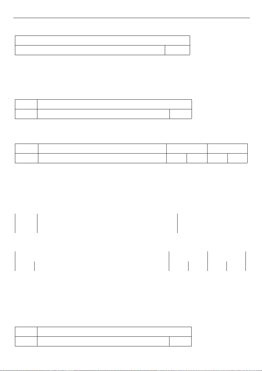
User manual - DATA RECORDER SRD-99 and cooperating software
The answer:
ADDR FUNC BYTE C DATA H,L CRC L,H
01 03 02 00 FF F8 04
DATA H, L - displayed value = 255, no decimal point. Decimal point position can be
read from reg. 43h (position of decimal point for channel 1)
4. Read of the registers 1, 2 and 3 in one message (example of reading a number of
registries in one frame):
ADDR FUNC REG H,L COUNT H,L CRC L,H
01 03 00 01 00 03 54 0B
COUNT L - the count of being read registers (max. 32)
The answer:
ADDR FUNC BYTE C DATA H1,L1 DATA H2,L2 DATA H3,L3 CRC L,H
01 03 06 00 0A 00 02 02 80 18 74
DATA H1, L1 - 01h registry (10 – value displayed for channel 1, no decimal point),
DATA H2, L2 - 02h registry (2 – value displayed for channel 2, no decimal point),
DATA H3, L3 - 03h registry (640 – value displayed for channel 3, no decimal point).
5. Setting of name for channel 1 as "Channel 1 "
(example of writing a number of registries in one frame)
ADDR FUNC REG H,L COUNT H,L BYTE C
01 10 00 47 00 05 0A
continue of frame:
DATA H1,L1 DATA H2,L2 DATA H3,L3 DATA H4,L4 DATA H5,L5 CRC L,H
43 68 61 6E 6E 65 6C 20 31 20 7F D0
DATA H1, L1 - 47h registry (43h - character "C", 68h - character "h"),
DATA H2, L2 - 48h registry (61h - character "a", 6Eh - character "n"),
DATA H3, L3 - 49h registry (6Eh - character "n", 65h - character "e"),
DATA H4, L4 - 4Ah registry (6Ch - character "l", 20h - space " "),
DATA H5, L5 - 4Ah registry (31h - character "1", 20h - space " ").
a) The answer (we assume that input current is not out of range):
ADDR FUNC REG H,L COUNT H,L CRC L,H
01 10 00 47 00 05 B0 1F
71
Page 72
User manual - DATA RECORDER SRD-99 and cooperating software
b) The answer (if an error occur):
ADDR FUNC ERR CRC L,H
01 90 08 4D C6
ERR - error code (08 - registry writing blocked by “
Config change
” parameter in “
RS485
port settings
” menu)
6. Change of baud rate of all devices connected to the net (BROADCAST message).
ADDR FUNC REG H,L COUNT H,L CRC L,H
00 06 00 22 00 04 29 D2
DATA H - 0
DATA L - 4, new baud rate 19200 baud
Device do not reply to BROADCAST-type messages.
There is no full implementation of the Modbus Protocol in the device. The
functions presented above are available only.
72
i
Page 73
User manual - DATA RECORDER SRD-99 and cooperating software
10. USER'S SETTINGS LIST
Parameter Description Value
Description
page
Parameters in the "Measurements list options” menu
List type Type of measurement results list 42
Date, Time Position of time line on historical list 43
Parameters in the "Graph options” menu
Scale Setting time scale 43
Parameters in the "Channels list options” menu
Display Method of displaying results 43
Parameters in the “Device information ” menu
Version Device firmware version 45
Serial no Device serial number 45
Memory Available device's memory 45
Used Used memory 45
Time left Time until memory is full 45
Parameters in the “Display options ” menu
Backlight Method of display backlight operation 45
Brightness Brightness of display backlight 45
Contrast Display contrast 45
Parameters in the “Logging setup” menu
Write Recording mode 46
Triggering
Method of measurement recording, digital
input function
47
Rec. period Time interval for measurement recording 47
Channel 1 Type of recorded value 47
Channel 2 Type of recorded value 47
Channel 3 Type of recorded value 47
Channel 4 Type of recorded value 47
Channel 5 Type of recorded value 47
Channel 6 Type of recorded value 47
Channel 7 Type of recorded value 47
Channel 8 Type of recorded value 47
Settings for Channel 1 in “Inputs settings” menu
Name Measurement channel name 49
73
Page 74
User manual - DATA RECORDER SRD-99 and cooperating software
Parameter Description Value
Description
page
Unit Unit for measured value 50
Input type Type of input/sensor 50, 53
Hi value
Value displayed for maximum value of input
current
50, 53
Lo value
Value displayed for minimum value of input
current
50, 53
Dec. point Position of the decimal point 50
Filter Level of filtration of indications 49
Bias Shifting of measurement scale 53
Upper ext. Upper extension of measurement range 51
Lower ext. Lower extension of measurement range 51
AL1 mode Alarm 1 generation mode 49
Threshold 1 Threshold of alarm 1 49
Hysteresis 1 Hysteresis of alarm 1 49
AL2 mode Alarm 2 generation mode 49
Threshold 2 Threshold of alarm 2 49
Hysteresis 2 Hysteresis of alarm 2 49
Settings for Channel 2 in “Inputs settings” menu
Name Measurement channel name 49
Unit Unit for measured value 50
Input type Type of input/sensor 50, 53
Hi value
Value displayed for maximum value of input
current
50, 53
Lo value
Value displayed for minimum value of input
current
50, 53
Dec. point Position of the decimal point 50
Filter Level of filtration of indications 49
Bias Shifting of measurement scale 53
Upper ext. Upper extension of measurement range 51
Lower ext. Lower extension of measurement range 51
AL1 mode Alarm 1 generation mode 49
Threshold 1 Threshold of alarm 1 49
Hysteresis 1 Hysteresis of alarm 1 49
AL2 mode Alarm 2 generation mode 49
Threshold 2 Threshold of alarm 2 49
74
Page 75
User manual - DATA RECORDER SRD-99 and cooperating software
Parameter Description Value
Description
page
Hysteresis 2 Hysteresis of alarm 2 49
Settings for Channel 3 in “Inputs settings” menu
Name Measurement channel name 49
Unit Unit for measured value 50
Input type Type of input/sensor 50, 53
Hi value
Value displayed for maximum value of input
current
50, 53
Lo value
Value displayed for minimum value of input
current
50, 53
Dec. point Position of the decimal point 50
Filter Level of filtration of indications 49
Bias Shifting of measurement scale 53
Upper ext. Upper extension of measurement range 51
Lower ext. Lower extension of measurement range 51
AL1 mode Alarm 1 generation mode 49
Threshold 1 Threshold of alarm 1 49
Hysteresis 1 Hysteresis of alarm 1 49
AL2 mode Alarm 2 generation mode 49
Threshold 2 Threshold of alarm 2 49
Hysteresis 2 Hysteresis of alarm 2 49
Settings for Channel 4 in “Inputs settings” menu
Name Measurement channel name 49
Unit Unit for measured value 50
Input type Type of input/sensor 50, 53
Hi value
Value displayed for maximum value of input
current
50, 53
Lo value
Value displayed for minimum value of input
current
50, 53
Dec. point Position of the decimal point 50
Filter Level of filtration of indications 49
Bias Shifting of measurement scale 53
Upper ext. Upper extension of measurement range 51
Lower ext. Lower extension of measurement range 51
AL1 mode Alarm 1 generation mode 49
Threshold 1 Threshold of alarm 1 49
75
Page 76
User manual - DATA RECORDER SRD-99 and cooperating software
Parameter Description Value
Description
page
Hysteresis 1 Hysteresis of alarm 1 49
AL2 mode Alarm 2 generation mode 49
Threshold 2 Threshold of alarm 2 49
Hysteresis 2 Hysteresis of alarm 2 49
Settings for Channel 5 in “Inputs settings” menu
Name Measurement channel name 49
Unit Unit for measured value 50
Input type Type of input/sensor 50, 53
Hi value
Value displayed for maximum value of input
current
50, 53
Lo value
Value displayed for minimum value of input
current
50, 53
Dec. point Position of the decimal point 50
Filter Level of filtration of indications 49
Bias Shifting of measurement scale 53
Upper ext. Upper extension of measurement range 51
Lower ext. Lower extension of measurement range 51
AL1 mode Alarm 1 generation mode 49
Threshold 1 Threshold of alarm 1 49
Hysteresis 1 Hysteresis of alarm 1 49
AL2 mode Alarm 2 generation mode 49
Threshold 2 Threshold of alarm 2 49
Hysteresis 2 Hysteresis of alarm 2 49
Settings for Channel 6 in “Inputs settings” menu
Name Measurement channel name 49
Unit Unit for measured value 50
Input type Type of input/sensor 50, 53
Hi value
Value displayed for maximum value of input
current
50, 53
Lo value
Value displayed for minimum value of input
current
50, 53
Dec. point Position of the decimal point 50
Filter Level of filtration of indications 49
Bias Shifting of measurement scale 53
Upper ext. Upper extension of measurement range 51
76
Page 77
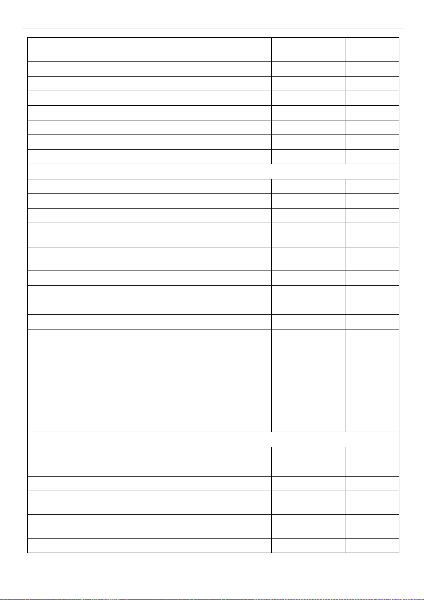
User manual - DATA RECORDER SRD-99 and cooperating software
Parameter Description Value
Description
page
Lower ext. Lower extension of measurement range 51
AL1 mode Alarm 1 generation mode 49
Threshold 1 Threshold of alarm 1 49
Hysteresis 1 Hysteresis of alarm 1 49
AL2 mode Alarm 2 generation mode 49
Threshold 2 Threshold of alarm 2 49
Hysteresis 2 Hysteresis of alarm 2 49
Settings for Channel 7 in “Inputs settings” menu
Name Measurement channel name 49
Unit Unit for measured value 50
Input type Type of input/sensor 50, 53
Hi value
Value displayed for maximum value of input
current
50, 53
Lo value
Value displayed for minimum value of input
current
50, 53
Dec. point Position of the decimal point 50
Filter Level of filtration of indications 49
Bias Shifting of measurement scale 53
Upper ext. Upper extension of measurement range 51
Lower ext. Lower extension of measurement range 51
AL1 mode Alarm 1 generation mode 49
Threshold 1 Threshold of alarm 1 49
Hysteresis 1 Hysteresis of alarm 1 49
AL2 mode Alarm 2 generation mode 49
Threshold 2 Threshold of alarm 2 49
Hysteresis 2 Hysteresis of alarm 2 49
Settings for Channel 8 in “Inputs settings” menu
Name Measurement channel name 49
Unit Unit for measured value 50
Input type Type of input/sensor 50, 53
Hi value
Value displayed for maximum value of input
current
50, 53
Lo value
Value displayed for minimum value of input
current
50, 53
Dec. point Position of the decimal point 50
77
Page 78

User manual - DATA RECORDER SRD-99 and cooperating software
Parameter Description Value
Description
page
Filter Level of filtration of indications 49
Bias Shifting of measurement scale 53
Upper ext. Upper extension of measurement range 51
Lower ext. Lower extension of measurement range 51
AL1 mode Alarm 1 generation mode 49
Threshold 1 Threshold of alarm 1 49
Hysteresis 1 Hysteresis of alarm 1 49
AL2 mode Alarm 2 generation mode 49
Threshold 2 Threshold of alarm 2 49
Hysteresis 2 Hysteresis of alarm 2 49
Output 1 settings in submenu ”Outputs settings”
Mode Output mode 54
Logic funct. Logic function mode 54
Source: channel 1 Channel 1 alarmstate source 54
Source: channel 2 Channel 2 alarm state source 54
Source: channel 3 Channel 3 alarm state source 54
Source: channel 4 Channel 4 alarm state source 54
Source: channel 5 Channel 5 alarm-state source 54
Source: channel 6 Channel 6 alarm-state source 54
Source: channel 7 Channel 7 alarm-state source 54
Source: channel 8 Channel 8 alarm-state source 54
Close delay Close switch delay time 54
Open delay Open switch delay time 54
Closed hold time Time for holding the closed state 54
Open hold time Time for holding the open state 54
Output 2 settings in submenu ”Outputs settings”
Mode Output mode 54
Logic funct. Logic function mode 54
Source: channel 1 Channel 1 alarm state source 54
Source: channel 2 Channel 2 alarm state source 54
Source: channel 3 Channel 3 alarm state source 54
Source: channel 4 Channel 4 alarm state source 54
Source: channel 5 Channel 5 alarm state source 54
Source: channel 6 Channel 6 alarm state source 54
78
Page 79

User manual - DATA RECORDER SRD-99 and cooperating software
Parameter Description Value
Description
page
Source: channel 7 Channel 7 alarm state source 54
Source: channel 8 Channel 8 alarm state source 54
Close delay Close switch delay time 54
Open delay Open switch delay time 54
Closed hold time Time for holding the closed state 54
Open hold time Time for holding the open state 54
Parameters in the “RS485 port settings” menu
Address Device address 56
Baud rate Baud rate 56
Resp. delay Delay of device response 56
Conf. change
Permission for modifying unit’s parameters
through RS-485 interface
56
Parameters in the “USB options” menu
Automatic write of
registered data
Permission for auto data write 58
Language User interface language 58
79
Page 80

User manual - DATA RECORDER SRD-99 and cooperating software
II. USER MANUAL FOR “ LOGGY SOFT ”
System requirements:
At least i486 computer,
Colour monitor with minimum resolution of 640 x 480,
20 MB of free hard drive space.
Designed for Windows
tested on Windows® XP, Windows® Vista, Windows® 7, Windows® 8
1. GENERAL CHARACTERISTICS
The
Loggy Soft
program enables the visualization, archiving and printing of
measurements (e.g. temperature, humidity, pressure) stored in memory of device such as
Data Logger with monochrome display
. Work with
Data Logger
devices takes place
through an RS-485 serial interface, or via the USB FlashDrive (PenDrive) device (optional
interface). Connecting a network of units to a serial port (RS 232) or USB port of a PC is
possible using a proper converter (RS-485 to RS-232 or RS-485 to USB).
2. INSTALLATION A ND STARTUP
The
LoggySoft-install
file is designed to install the program. The install file is located in
Loggy Soft
folder on CD delivered with device.
During installation follow the directions provided by
Installation wizard.
The wizard will
create a folder called
Loggy Soft
on the computer’s hard drive, the program files will be
placed in this folder. The shortcut to the program will be placed in a location specified by the
user.
Manual startup of the program is done using the
Loggy.exe
executable file.
Initial startup of the application enables detection of all
Data Logger
devices present in
the network. The user is asked to perform devices installation and measurement channel
configuration procedure for all detected devices.
Follow the guidelines in the windows displayed by the program.
WARNING!
There is no need of detecting the devices using USB FlashDisk data download at
this point. Devices of that kind will be detected and installed later, during the first data
download. If the system consist of FlashDisk-served devices only, you can skip the following
installation steps by pressing
[FLASH DRIVE only]
button.
To continue installation procedure, click on the [
Next>>
] button.The next screen (
Fig. 2.1
)
enables the selection of the number for the RS 232 serial port for the converter, and the
transmission speed. The number of chosen for the selected port must comply with number of
the port to which the converter is connected.
80
Page 81
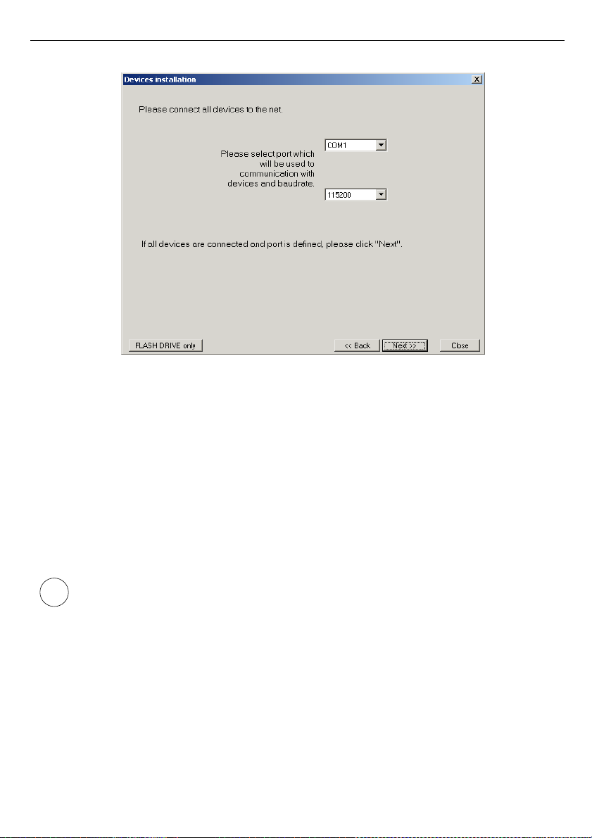
User manual - DATA RECORDER SRD-99 and cooperating software
Fig. 2.1. Selection of serial port and baud rate
After defining the communications port and baud rate, go to device detection screen (
Fig. 2.2
)
by clicking on the [
Next>>
] button.
Prior to scanning the network for devices, set the addresses identifying the selected devices in
the network (a different address for each device – see page 56). In order to detect units
connected to the network (after assigning addresses to the devices) press the [
Scan network
]
button.
Address set in the unit should be in 1÷254 range. Devices with not changed
address will not be found by software !
81
i
Page 82
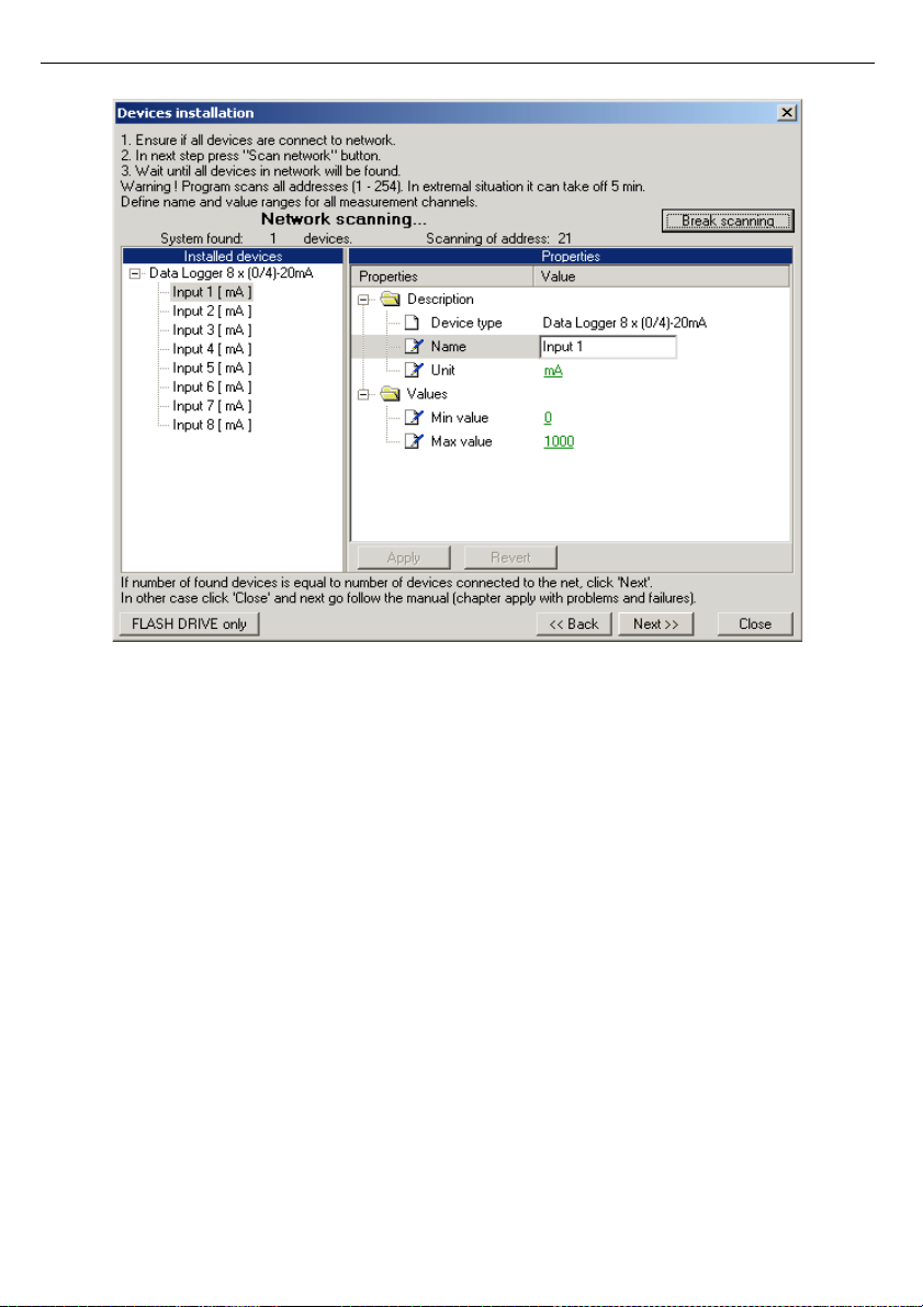
User manual - DATA RECORDER SRD-99 and cooperating software
Fig. 2.2. Scanning network for devices
The list shown on the figure (Fig. 2.2) contains one detected device. Order of devices on the
list corresponds to the order of addresses assigned by the user to individual devices. Once all
devices are detected press [
Break scanning
] button.
„Properties”
list available in right part of the window allows configuration of measurement
channels. Appropriate names (e.g. the location where the sensor connected to this channel
was installed), unit denotation and allowable measured values (minimum and maximum)
should be assigned to measurement channels of detected devices. In case these values are
exceeded during system operation an alarm message will be displayed.
After pressing the [
Next>>
] button the final installation screen will be displayed.
82
Page 83
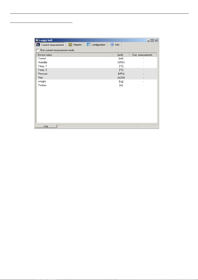
User manual - DATA RECORDER SRD-99 and cooperating software
3. USING THE PROGRAM
Upon application startup the
Current measurement
menu is displayed (
Fig. 3.1
).
Fig. 3.1Program window upon startup
The selection from the currently active menu is made using the flat buttons in the upper
part of the program window (
Fig. 3.1
). Three positions are available:
•
Current measurement
- menu for current measurements visualizing;
•
Reports
- menu for visualizing and printing reports;
•
Configuration
- menu for changing system settings and defining measurement
channel groups;
•
Info
- menu containing program information.
Button
[Log]
located in bottom part of the main window allows opening/closing additional
window with messages related to the program execution. These messages window is opened
automatically when new message appears.
83
Page 84
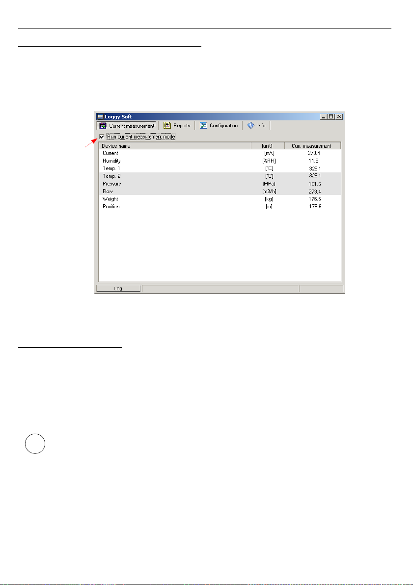
User manual - DATA RECORDER SRD-99 and cooperating software
3.1. „ CURRENT MEASUREMENT
” MENU
Current measurement
menu allows to view current measurements results in table
format. This table contains measures of channels of all installed devices. Only the
measurements from devices installed using the RS-485 interface will be available. To enable
continuous reading of data from the devices check
Enable current measurement mode
.
Presently read data will be showed in column named
Current measurement
.
Fig. 3.2. Current measurement menu
3.2. „ REPORTS ” MENU
Reports
menu is used to view and print reports containing recorded measurement
results in the form of tables or graphs. This menu also enables export of measurement data to
a text format file.
Creating new reports is possible in two modes:
• for a group (collective report for a maximum of 12 measurement channels),
• for a single channel.
Creating a report for a channel belonging to a removed device is possible only in
single channel mode.
84
i
Current
measurement
enable field
Page 85
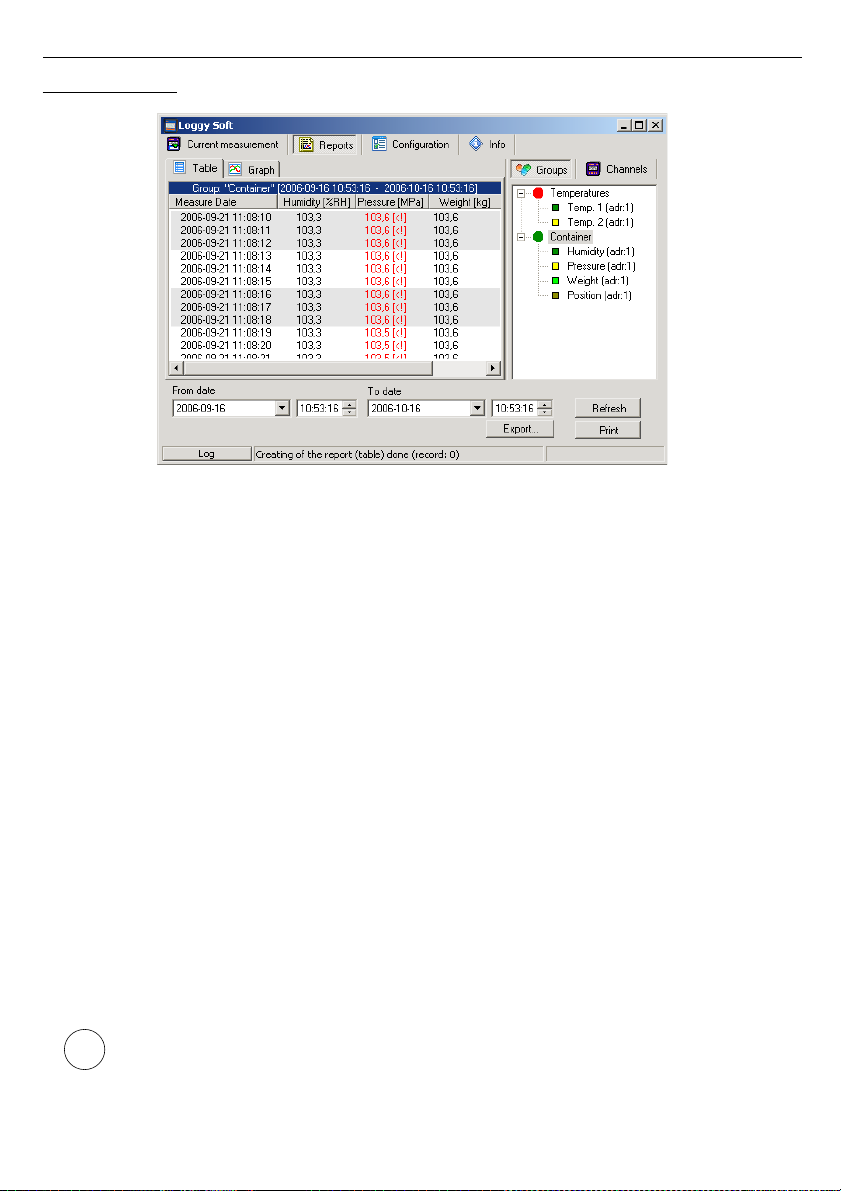
User manual - DATA RECORDER SRD-99 and cooperating software
3.2.1. „ Table ” tab
Fig. 3.3. Reports - menu
The
Table
tab (
Fig. 3.3
) is used for printing information concerning recorded measurements
(e.g. temperature, humidity) in the form of a table for one of the groups or a particular
measurement channel selected by the user (for more information on groups see
3.3.2
section,
at page 97). This tab also enables the export of data to text format files. The exported file is
formatted in a way allowing the transfer of data to a calculation sheet.
A table consisting of columns containing measurement date and value (for one or a number of
channels) is displayed in the centre of the tab. The remaining elements of the
Table
tab are:
•
From date
- this is the date and time defining the beginning of analysed
measurement recording period for printing in the form of a table,
•
To date
- this is the date and time defining the end of analysed measurement
recording period for printing in the form of a table (this does not have to
be the current date),
•
[Print]
button - prints the report,
•
[Refresh]
button - updates the displayed data
•
[Export...]
button - exports data to a text or csv file
•
Groups/Channels
- this box enables creating tables in two modes:
- for a group - collective table for a maximum of 12 measurement channels
(observed channels can belong to different devices),
- for a single channel.
Creating groups is described in the
Group operations
section (page 97).
85
i
Page 86
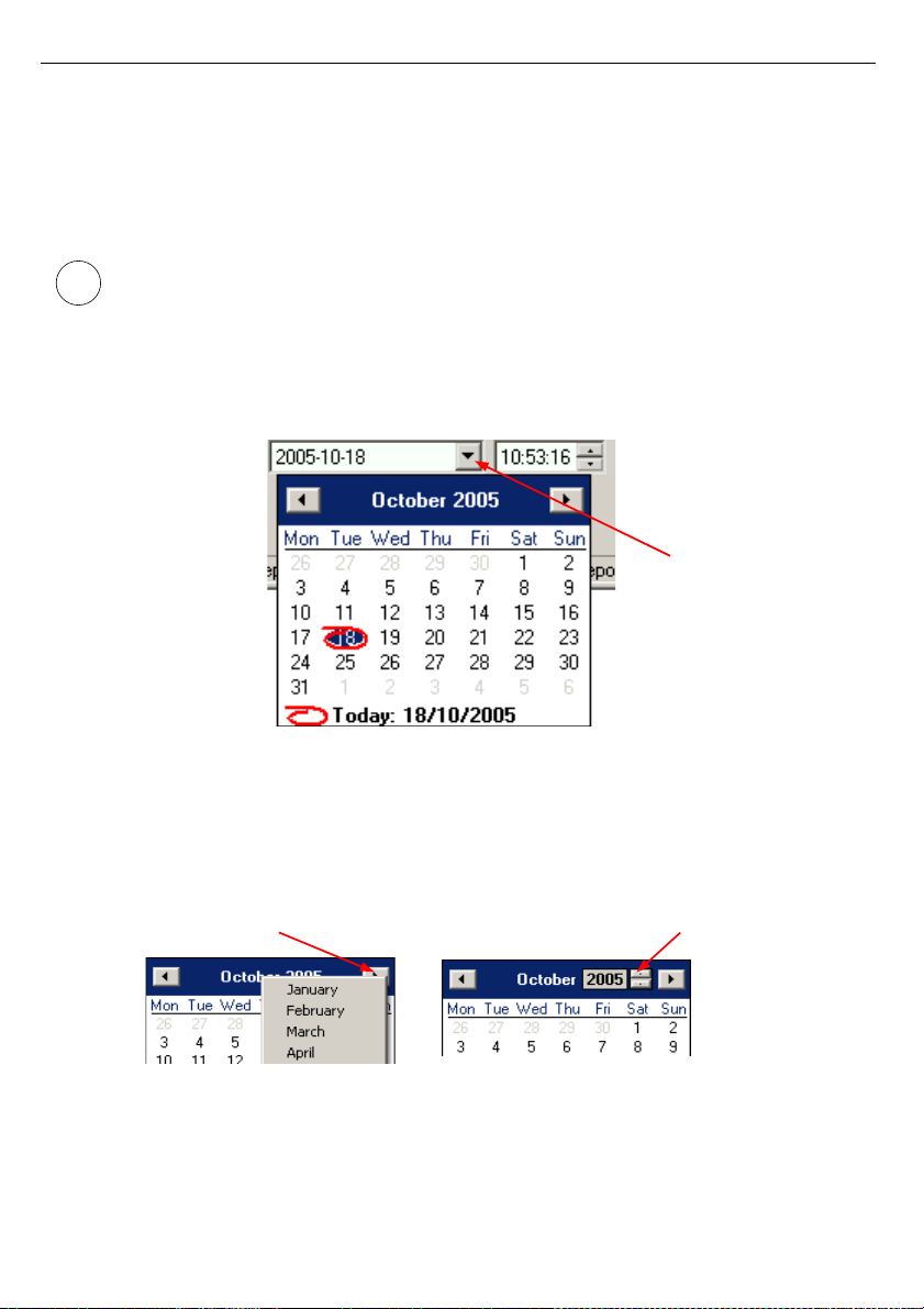
User manual - DATA RECORDER SRD-99 and cooperating software
Selecting table type (for a group or single channel)
In order to select table type:
• click appropriate tab
Groups
or
Channels
(
Fig. 3.3
),
• check specific group or measurement channel. This will display measurement results for
the selected group or single channel (displaying results takes place automatically after
each change of group or measurement channel).
In order to use table for groups the group must be created first. Creating groups is
described in the
Group operations
section (
3.3.2
, page 97).
Change of “From date” or “To date”
1)
In order to change “From date” or “To date” date, click onto the arrow on right side of the
date (
Fig. 3.4
). The calendar window will open:
Fig. 3.4. Changing the “From date”
2)
The date can be change by clicking onto any day in the calendar. Buttons at the top part of
the calendar are used to change months (
Fig. 3.5
). After clicking on the current year
located to the right from month’s name an edition window and buttons for changing the
year are displayed (
Fig. 3.5)
.
Fig. 3.5. Changing months and year
86
i
Date change button
month change button
year change button
Page 87

User manual - DATA RECORDER SRD-99 and cooperating software
3)
The time can be changed by clicking on the box, in which it is displayed and manually
typing it in using the keyboard.
4)
The operation is completed by pressing the [
Refresh
] button; this will update the data
shown in the table.
3.2.2. „ Graph ” tab
Fig. 3.6. Reports - Graph tab
Graph
tab (
Fig. 3.6
) is used for viewing and printing of measurement results recorded by
device (e.g. temperature, humidity) in the form of a graph. Measurements from a maximum of
five recorded measurement channels can be viewed.
The
Graph
tab contains such elements as:
•
graphs area
- plots measured values (e.g. temperature, humidity) in function of time.
Each channel is distinguished by a different colour (
Fig. 3.6
);
•
From date
- this is the date and time defining the beginning of analysed
measurement recording period for printing in the form of a graph;
•
To date
- this is the date and time defining the end of analysed measurement
recording period for printing in the form of a graph (this does not have to
be the current date);
•
[Print]
button - prints the report;
87
Page 88

User manual - DATA RECORDER SRD-99 and cooperating software
•
[Refresh]
button - updates the displayed data;
•
Show cursor
field - check this field to activate special graphical cursor which allows to
track measurement points of the selected channel graph.
•
Groups/Channels
- this box enables creating graphs in two modes:
- for a group - collective graph for a maximum of 12 measurement channels
(observed channels can belong to different devices);
- for a single channel.
Creating groups is described in the
Group operations
section (
3.3.2
, page 97).
Selecting graph type (for a group or single channel)
In order to select table type:
• click appropriate tab
Groups
or
Channels
(
Fig. 3.6
),
• check specific group or measurement channel. This will display measurement results for
the selected group or single channel (displaying results takes place automatically after
each change of group or measurement channel).
In order to use table for groups the group must be created first. Creating groups is
described in the
Group operations
section (
3.3.2
, page 97).
Change of “From date” or “To date”
Change of start and end date take place the same way as in
Table
tab (see page 86).
Changing the graph display method
Following operations are available for the
graph area
:
•
enlarge graph
- a graph can be enlarged by marking the area of interest with the
mouse pointer. In order to do this first left-click on the graph and,
while holding down the left mouse button, drag the pointer to the
bottom right corner of the graph. The rectangle marked this way will
be enlarged (
Fig. 3.7
).
88
i
i
Page 89
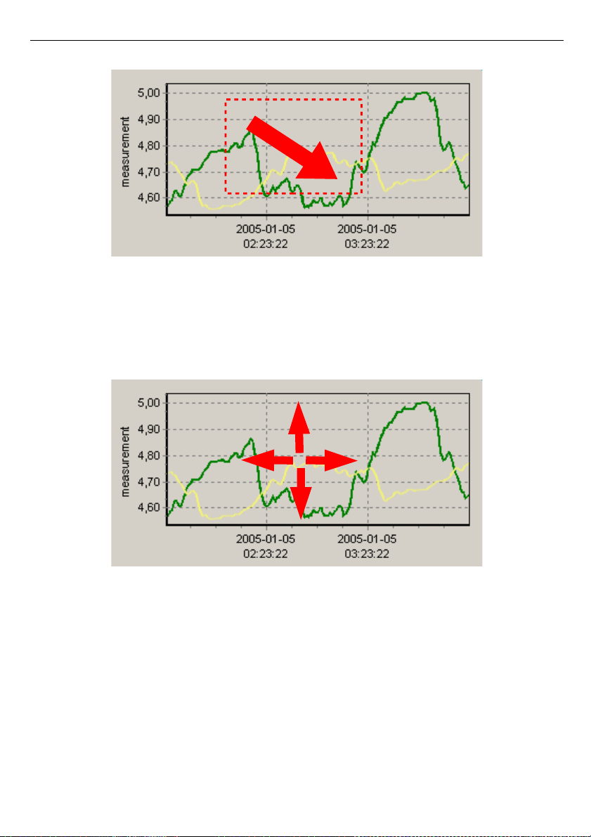
User manual - DATA RECORDER SRD-99 and cooperating software
Fig. 3.7. Enlarging graph
•
moving the graph
- the graph can be moved to the left/right (earlier/later time period,
correspondingly). In order to do this, right-click on the graph and
drag the pointer in desired direction (
Fig. 3.8
).
Fig. 3.8. Moving the graph
89
Page 90
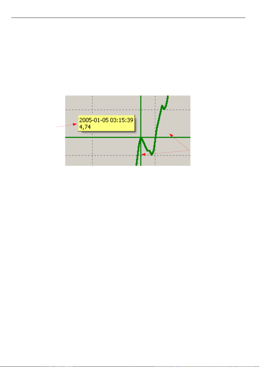
User manual - DATA RECORDER SRD-99 and cooperating software
•
measurement points tracking
- if
Show cursor
field is checked then special graphical
cursor is displayed on the graph. This cursor allows to
easy tracking of measured data. Colour of the cursor is
same as selected channel colour. To change selection
click left mouse button until cursor became same colour
as desired channel. Near to the cursor informations about
selected point are displayed. Date and time of recording
and value of the registered measurement point.
Fig. 3.9. Graph with special tracking cursor
•
restoring default values
- the [
Refresh
] button enables returning to
initial
graph in 1:1 scale;
•
update the displayed measurements
- the [
Refresh
] button allows to update
measurement data displayed on the graph.
90
Informations about
measurement points
Cursor lines displayed
in graph colour
Page 91
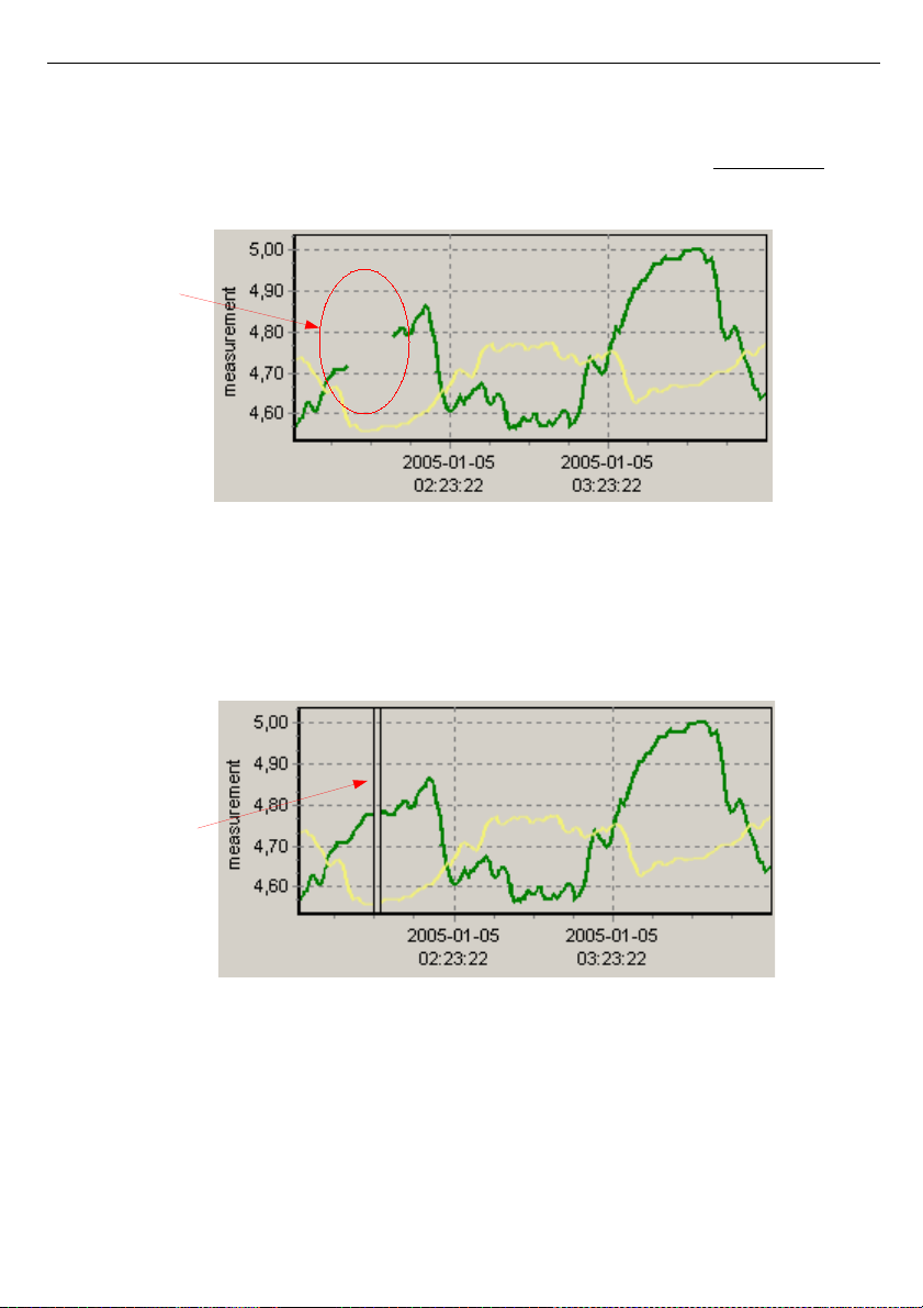
User manual - DATA RECORDER SRD-99 and cooperating software
Information on periodical lack of measurement
If any measurement channel, for whatever reasons (e.g. sensor fault), will not record
measurement values, then this situation will be presented on the graph as
interruption
in the
measurement (
Fig. 3.10
).
Fig. 3.10. Interruption in the graph (e.g. sensor fault)
If measurements can not be executed for some time (e.g. power supply fault or the device is
switched off) then the program will show this situation on the graph in the form of two vertical
lines (
Fig. 3.11
).
Fig. 3.11. Vertical lines on the graph - interruption of measurements
91
No measurement
values
Interruption of
measurements
Page 92

User manual - DATA RECORDER SRD-99 and cooperating software
Prior to analysing recorded measurement results, read the current data recorded by
devices. In order to download current data recorded by devices press the
[Download data (RS 485)]
button in the
Devices
tab in the
Configuration
menu,
or insert the USB FlashDrive (PenDrive) with logged data to PC USB port and
confirm the data download. The database of recorded measurements will be
updated.
3.3. „ CONFIGURATION
” MENU
The
Configuration
menu is used to:
• change the settings of channels of devices working in the system and getting data from
these devices (
Devices
tab);
• operations of groups (
Groups
tab),
• change the settings of program (
Settings
tab).
Parameters in tabs of
Configuration
menu can be edited after clicking on [
Show
advanced options
] button. (
Fig. 3.12
).
Fig. 3.12. Configuration menu (advanced options hidden)
The user will be asked to enter a password protecting against the changing of the settings by
an unauthorized person. Entering of proper password allows to edit parameters and displaying
of additional keys for devices adding / removing (
Fig. 3.13
). Default password is „srd system”.
92
i
Page 93
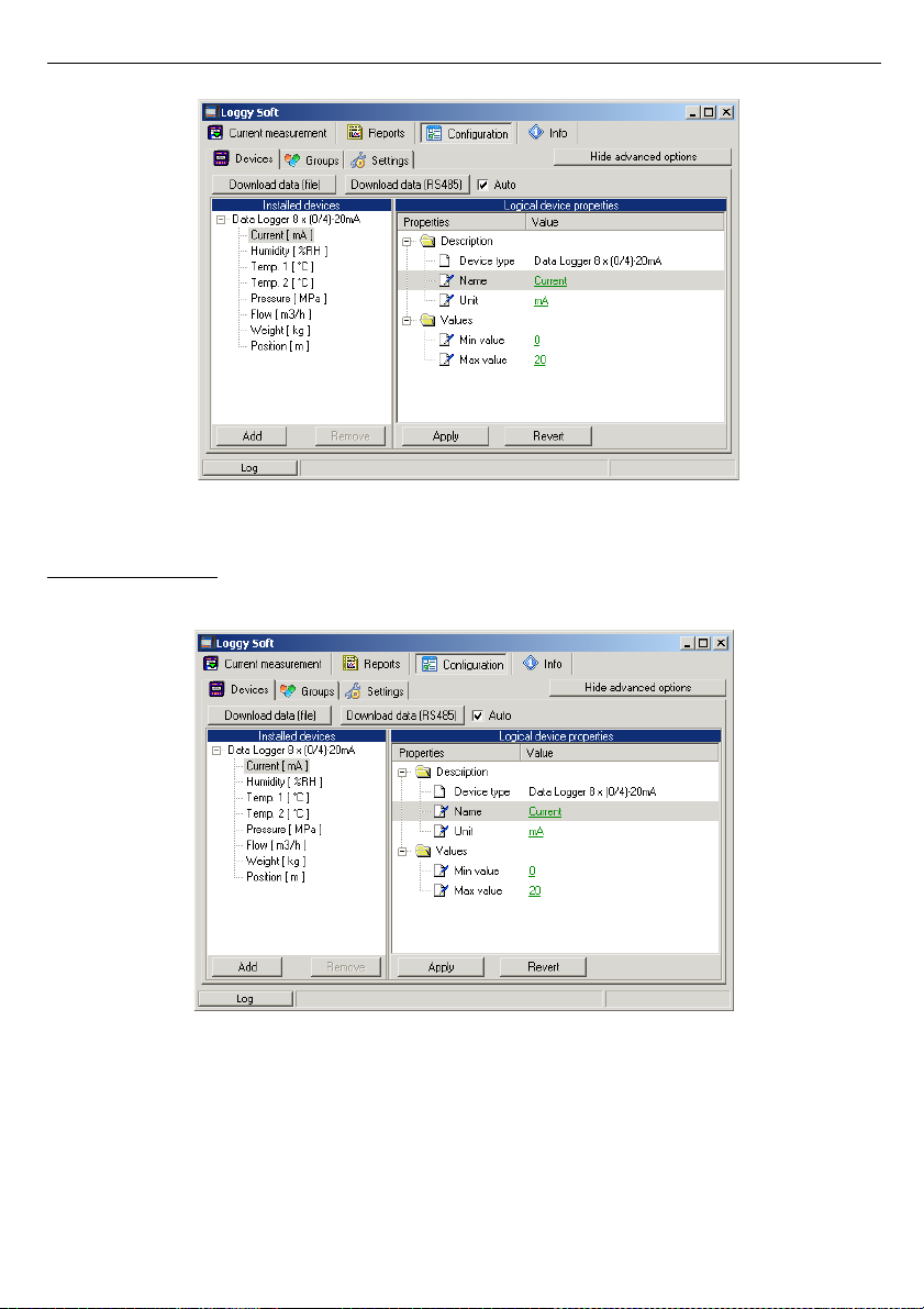
User manual - DATA RECORDER SRD-99 and cooperating software
Fig. 3.13. Configuration menu (advanced options active)
3.3.1. „ Devices ” tab
Fig. 3.14. Configuration - Devices tab (advanced options active)
93
Page 94

User manual - DATA RECORDER SRD-99 and cooperating software
The
Devices
tab (Fig. 3.14) contains such elements (fields) as:
•
Installed devices
- shows the tree contains a list of all currently installed
devices together with their addresses. The first level of
the tree shows individual devices. After clicking the “+”
sign next to the device name with mouse pointer, the
measurement channels corresponding to this device are
displayed. By clicking on one of devices we can see
measurement channels under names defined during
system installation (e.g. “Flow”).
•
[Add]
and
[Remove]
buttons - allow to add and remove installed devices from the
system,
• ...device properties
- shows the tree containing a list of properties of
selected device or channel. All parameter's values
(underlined) can be edited. All changed but not
approved (using
[Apply]
) values are showed in bold.
•
[Apply]
and
[Revert]
buttons - allow to memorize of changed parameters or revert
changed but not approved (using
[Apply]
) parameters.
•
[Download data (file)]
button - allows to read measurement data from files created
while data downloading using USB FlashDrive. After
selecting this command, user has to point location (folder
with files written by data logger) containing data to
download.
•
[Download data (RS485)]
- allows to read data stored in all devices installed using
RS-485 interface,
Changing of devices settings
The settings of devices can be changed by clicking on the
Devices
tab. Activation of
advanced options allows to edit parameters and displaying of additional keys for devices
adding / removing (
Fig. 3.15
).
94
Page 95
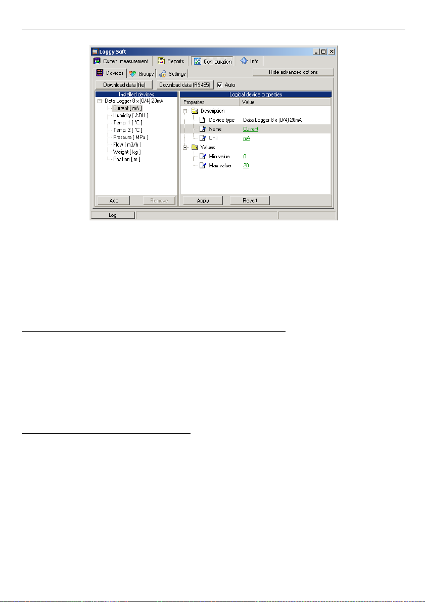
User manual - DATA RECORDER SRD-99 and cooperating software
Fig. 3.15. Devices adding and removing (advanced options active)
Downloading of registered data
Downloading of data stored on internal memory can be done in two ways:
• using USB FlashDisk (PenDrive)
• using RS-485 interface
Data downloading from Flash drive and selected localisation
The USB FlashDisk will be automatically detected if inserted to PC USB port, and the
user will be asked for confirmation of data download (if any data available on the inserted
disk).
Loggy Soft
allows to download data from any localisation (selected directory) by means
of
[Download data (file)]
button. This method should be used only if the logged data was
previously copied manually from FlashDrive to PC hard drive.
Data downloading via RS-485 interface
Default settings of data downloading via RS-485 allow to import only newest data, stored
since last downloading. This method prevents user against multiply downloading of stored
data, and reduces time of data downloading. Date of last download is automatically stored to
internal memory of logger while downloading initialised by pressing of
[Download data
(RS485)]
button.
In some cases there is a need to download already downloaded data again (failure of the
device, errors in database, lost of downloaded data). In such situations it is possible to
download data more than one time, but only if data is not overwritten or damaged.
95
Page 96

User manual - DATA RECORDER SRD-99 and cooperating software
To download data again enter
Advanced Settings
(password is required), then disable
Auto
option and select date of the begin of required data (
Fig. 3.16
). After that click
[Download
data (RS485)]
button.
Fig. 3.16. Downloading data using RS-485 interface (advanced options active)
If data downloading is broken unexpectedly or data is incomplete it can be result of
database damage. In such situation try download data again but omit damaged part of data
(range of time). For example if data were logged every 15 minutes, and data downloaded
lastly were stored
2009-07-28 17:15
, then set parameter
„From date:”
omitting one or more
data points. To omit one point only, set
2009-07-28 17:45
and click
[ Download data
(RS485)]
again.
Data can also be downloaded automatically at specific time intervals. Although the
memory capacity of device allows data logging at least for day, this functionality is especially
useful for continuous data protection on the server. A more detailed description of automatic
data download can be found in chapter
II 3.3.3
.
Data downloaded from devices, are stored to files "
YEAR-MONTH.mdb"
in subdirectory
"
bases
", while informations of devices connected to the network are stored to file "
main.mdb"
(
Fig. 3.17
). Regular backup of these files is recommended .
96
Page 97
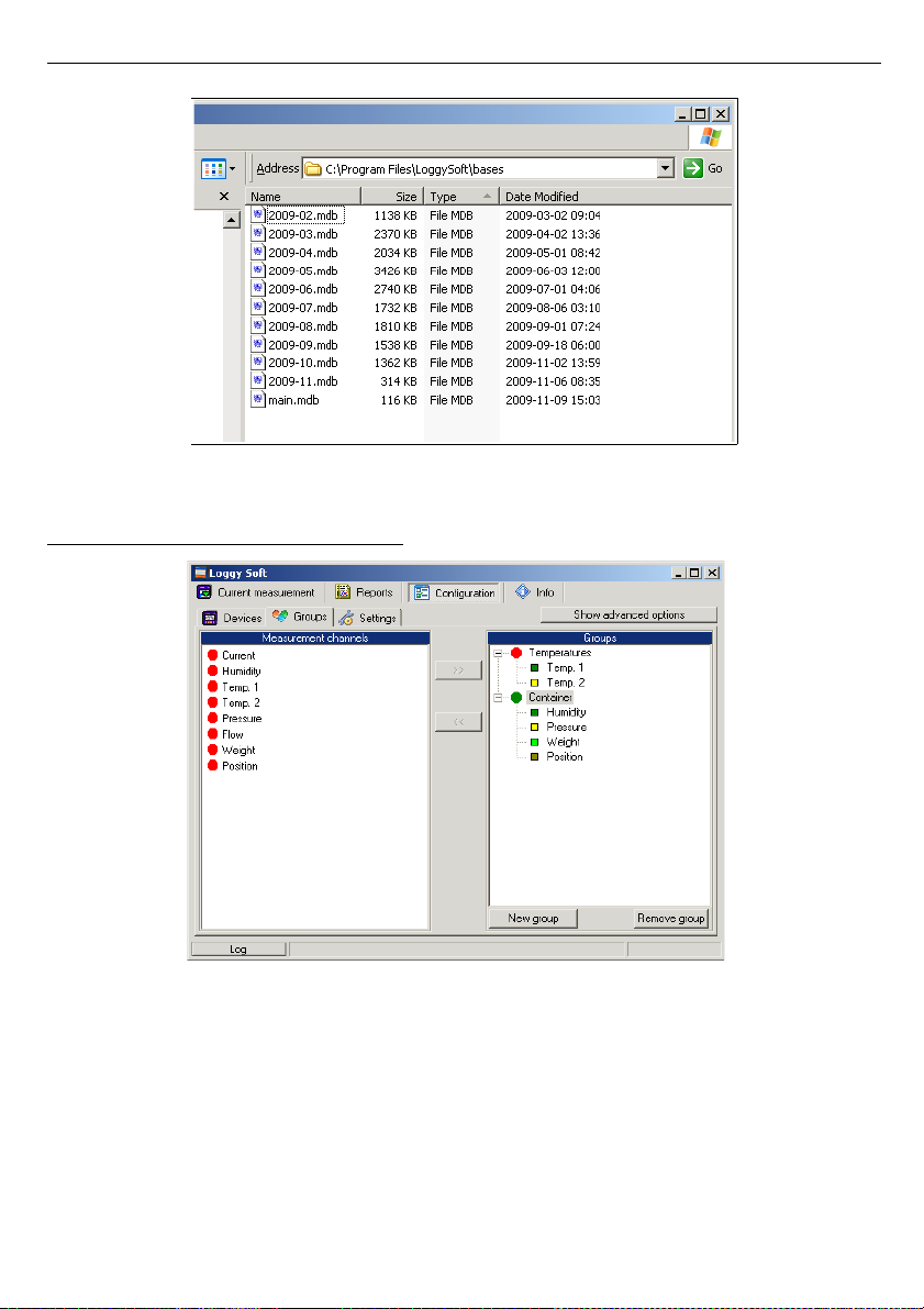
User manual - DATA RECORDER SRD-99 and cooperating software
Fig. 3.17. Contents of Loggy Soft measurement data folder
3.3.2. „Groups” tab - group operations
Fig. 3.18. Configuration - Groups tab
A
group
enables creating a collective current graph/report for a number of measurement
channels belonging to the same or to different devices, which the user wishes to view on one
graph/report. A group consists of a maximum of 12 measurement channels.
97
Page 98

User manual - DATA RECORDER SRD-99 and cooperating software
Typical methods of grouping measurement channels:
• measurement channels recording the measurements of the same physical value
(e.g. temperature or humidity),
• measurement channels recording the measurements from sensors located in the same
places, e.g. “Assembly room”.
One measurement channel can belong to different groups.
Creating a new group
In order to create a new group:
• click on the [
New group
] button,
• assign a name to the new group.
Removing a group
In order to remove a group:
• check the desired group on the
Groups
list,
• click on the
[Remove group]
button.
Changing group name
In order to change a group’s name:
• check the desired group on the
Groups
list,
• click on the group again,
• the group name will be highlighted - the name can be edited. The edit can be cancelled
(restore previous name) by pressing the [
ESC
] key.
Upon completing the edit, confirm changes with
[
ENTER
] key.
Adding measurement channels to a group
In order to add a measurement channel to a group:
• check the group, to which the channel is to be added (the checked group is marked with a
green circle),
• then check one, or (holding down the
[Ctrl]
key) many channels of
Measurement
channels
list,
• finish the procedure using the [>>] button.
A maximum of 12 channels can be added to one group.
Removing a measurement channel from a group
To remove a channel from a
Group
:
• find the desired group on the
Groups
list,
• show the list of devices in the group using “+” mark,
• check the measurement channel to be removed,
• finish the procedure using the
[<<]
button.
98
i
i
Page 99
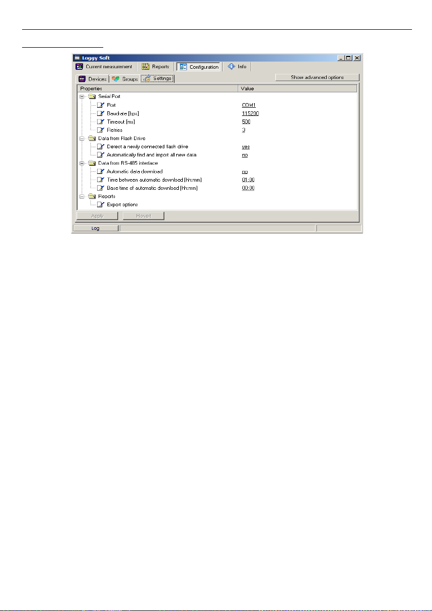
User manual - DATA RECORDER SRD-99 and cooperating software
3.3.3. „ Settings ” ta b
Fig. 3.19. Configuration - Settings tab (advanced options hidden)
Settings
tab (
Fig. 3.19
) allows to change settings related to serial port and method of data
downloading from the USB FlashDisk. The settings list contains following fields:
•
Port field
- used to change the computer’s communication
port to which the converter is connected,
•
Baudrate field
- defines baud rate,
•
Detect a newly connected Flash Drive
option
- enabling this option causes that if the user connects a flash drive
to the computer, the program asks him to search connected drive
for data files stored by data logger. If files that have been found
contain new data, program will display relevant information or data
will be imported automatically (if the option
Automatically find and
import all new data
is enabled),
•
Automatically find and import all new data
option
- enabling this option causes the program won't ask the user for
search data on connected Flash Drives, because it will always do.
Search result, so the import process, will be accepted automatically.
To make the data searched and imported automatically, the option
Detect a newly connected Flash Drive
must be enabled too,
•
Automatic data download
option
- enabling this option activates mechanism to automatically
download data from all data loggers installed in the program that
are connected to the computer via RS-485 interface. Begin of
download data will be triggered at specified time interval set in the
Time between automatic download
field,
99
Page 100
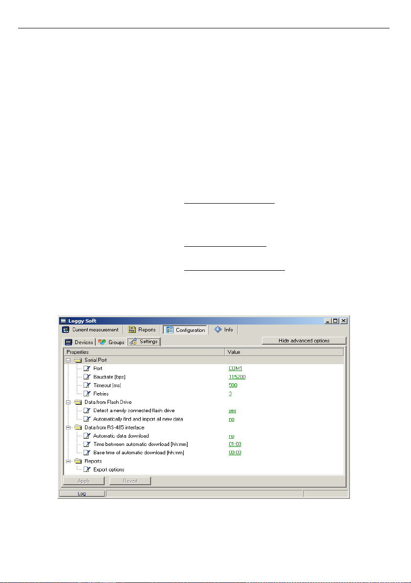
User manual - DATA RECORDER SRD-99 and cooperating software
•
Time between automatic download
field
- this field specifies the time interval between automatic download
new data from data loggers. This time can be set with precision to
one minute, but can't be longer than 23 hours and 59 minutes. The
starting point of counting intervals is specified by
Base time of
automatic downloa
d field,
•
Base time of automatic download
field
- this field specifies start time from which begins counting the first
and following automatic data download processes,
•
Export options
field
- settings that are here, affect the way of creation a file from
generated data using the
[Export...]
button accessible from
Reports
menu. These settings include:
• Exclude Min/Max info – if this option is active,
instead of information about exceeds minimum and
maximum values of measurements, numeric values
will be created, which may be incorrect,
• Exclude error name – instead of an error in the
measurement, the default numerical value appears,
• Separate date and time – it creates a separate
column for date and time.
In order to change these settings, make sure the advanced options mode is active. If
necessary, activate it by clicking on the button
[Show advanced options] (Fig. 3.20
).
Fig. 3.20. Configuration - Settings tab (advanced options active)
100
 Loading...