

Page 1
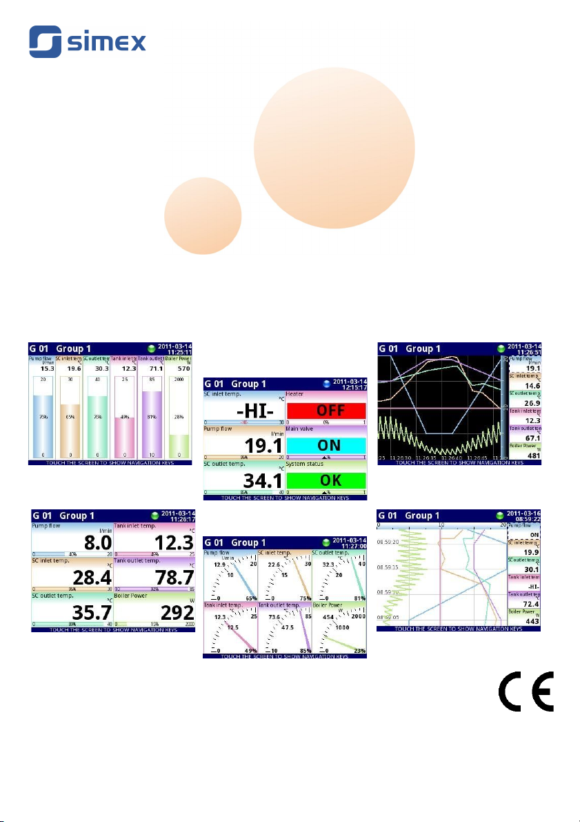
Assisting the automation
industry since 1986
User manual
CONTROLLER/DATA RECORDER
MultiCon CMC-99/141
•
Firmware: v.2.27.0 or higher
Read the user's manual carefully before starting to use the unit or software.
Producer reserves the right to implement changes without prior notice.
2016.06.01 MultiCon CMC-99/141_INSSXEN_v.1.17.015
Page 2

User Manual For - CONTROLLER/DATA RECORDER MultiCon CMC-99/141
CONTENTS
1. BASIC REQUIREMENTS AND USER SAFETY.......................................................................................5
1.1. THE USE OF TOUCH-SCREEN.......................................................................................................6
2. GENERAL CHARACTERISTICS...............................................................................................................6
3. TECHNICAL DATA....................................................................................................................................9
4. DEVICE INSTALLATION.........................................................................................................................10
4.1. UNPACKING...................................................................................................................................11
4.2. ASSEMBLY.....................................................................................................................................12
4.3. CONNECTION METHOD...............................................................................................................14
4.3.1. Available modules..................................................................................................................17
4.4. MAINTENANCE..............................................................................................................................31
5. INTRODUCTION TO MULTICON CMC-99/141.......................................................................................31
5.1. UNDERSTANDING CONTROLLER/DATA RECORDER MULTICON CMC-99/141.....................31
5.1.1. Logical channels....................................................................................................................32
5.1.2. Groups...................................................................................................................................34
5.2. HARDWARE CONFIGURATIONS ................................................................................................35
6. WORKING WITH THE MULTICON CMC-99/141....................................................................................36
6.1. MULTICON CMC-99/141 POWER UP...........................................................................................36
6.2. THE USE OF THE TOUCH-SCREEN............................................................................................36
6.3. DISPLAY.........................................................................................................................................36
6.3.1. Information bar.......................................................................................................................37
6.3.2. Navigation bar........................................................................................................................38
6.3.3. Data panels............................................................................................................................39
6.3.4. Important messages..............................................................................................................42
7. CONFIGURATION OF THE MULTICON CMC-99/141...........................................................................43
7.1. EDIT DIALOGUES..........................................................................................................................43
7.2. MAIN MENU SELECTION PANEL.................................................................................................46
7.3. FILES MANAGEMENT...................................................................................................................47
7.4. DEVICE INFORMATION, LICENCE, FIRMWARE UPDATE, REMOTE DISPLAY, EXPORT
MANUAL AND RENEW CONFIGURATION..........................................................................................53
7.5. DEVICE CONFIGURATION............................................................................................................56
7.6. CONFIGURATION MENU STRUCTURE.......................................................................................59
7.7. GENERAL SETTINGS....................................................................................................................63
7.8. LOGICAL CHANNELS....................................................................................................................67
7.8.1. Logical Channels - General settings.....................................................................................67
7.8.2. Logical channels - Hardware input mode..............................................................................84
7.8.3. Logical Channels - Hardware output monitor mode..............................................................87
7.8.4. Logical Channels - Modbus mode.........................................................................................89
7.8.5. Logical Channels - Set point value mode..............................................................................92
7.8.6. Logical Channels - Math function mode................................................................................95
7.8.7. Logical Channels - Controller mode....................................................................................105
7.8.8. Logical Channels - Profile/timer mode.................................................................................107
7.8.9. Logical Channels - Profile/timer (cycle counter) mode........................................................109
7.8.10. Logical Channels - Data from other channel mode...........................................................110
7.8.11. Examples of Logical Channels configuration....................................................................111
7.8.11.1. Application of Logical channel in the Hardware input mode for UI4 module...111
7.8.11.2. Application of Logical channel in the Hardware input mode for TC4 modules 118
7.8.11.3. Application of Logical channel in the Hardware input mode for RT4 modules 121
7.8.11.4. Application of Logical channel in the Hardware output monitor mode for R45
modules.............................................................................................................................123
7.8.11.5. Application of Logical channel in the Modbus mode........................................125
7.8.11.6. Application of Logical channel in the Hardware input for TC8 modules..........127
7.8.11.7. Application in Math function mode....................................................................129
7.8.11.8. Application of Logical channel in the Controller mode.....................................131
7.8.11.9. Application of Logical channel in the Profile/timer mode.................................133
7.8.11.10. Application of Logical channel in the Hardware input mode and Data from
2
Page 3

User Manual For - CONTROLLER/DATA RECORDER MultiCon CMC-99/141
other channel for FT4 module...........................................................................................135
7.9. BUILT-IN INPUTS.........................................................................................................................137
7.9.1. Built-in inputs - General settings.........................................................................................137
7.9.2. Built-in inputs - Input modules.............................................................................................139
7.9.3. Built-in inputs - Binary input Inp.X2 : Digital 24V................................................................139
7.9.4. Built-in inputs - Demo input numbered X3, X4, X5..............................................................140
7.9.5. Built-in inputs – Modules.....................................................................................................141
7.9.5.1. Voltage and current measurement modules........................................................141
7.9.5.2. Mixed UIN/UID modules......................................................................................141
7.9.5.3. Isolated current inputs module.............................................................................143
7.9.5.4. Analogue flowmeter modules..............................................................................143
7.9.5.5. Pulse flowmeter modules.....................................................................................144
7.9.5.6. Thermocouples sensor measurement modules..................................................145
7.9.5.7. RTD measurement modules................................................................................147
7.9.5.8. Isolated universal inputs modules.......................................................................147
7.9.5.9. Optoisolated digital inputs modules.....................................................................148
7.9.5.10. Optoisolated universal counters modules.........................................................148
7.9.5.11. Optoizolated hourmeters modules.....................................................................150
7.10. BUILT-IN OUTPUTS...................................................................................................................152
7.10.1. Built-in outputs - General settings.....................................................................................152
7.10.2. Built-in Output - Relays, Sound signal, Virtual relays.......................................................154
7.10.3. Build-in output - PWM (Pulse-width modulation) mode for SSR relay output..................158
7.10.4. Built-in output - Current output..........................................................................................160
7.10.5. Examples of build-in output configurations.......................................................................162
7.10.5.1. Application of the output for R45 modules.......................................................162
7.10.5.2. Application of output for IO modules................................................................164
7.11. EXTERNAL OUTPUTS...............................................................................................................165
7.11.1. External outputs - General settings...................................................................................165
7.11.2. External outputs - Control type: as a relay........................................................................167
7.11.3. External outputs - Control type: as a linear output............................................................169
7.11.4. Examples of external output configurations......................................................................171
7.11.4.1. Application of external output for protocol Modbus in the MASTER mode.......171
7.12. PROFILES/TIMERS....................................................................................................................174
7.12.1. Profile/timer - General settings..........................................................................................174
7.12.2. Profiles/timers - Triggering mode: level (gate), edge (once), edge (retrig.)......................178
7.12.3. Profiles/timers - Triggering mode: on time........................................................................180
7.12.4. Examples of Profile/timer configurations...........................................................................182
7.12.4.1. Application of the Profiles/timers......................................................................182
7.12.4.2. Application of the Profiles/timers triggered on time..........................................184
7.13. CONTROLLERS.........................................................................................................................186
7.13.1. Controllers - General settings............................................................................................186
7.13.2. Examples of Controller configurations...............................................................................189
7.13.2.1. Application of the Controllers............................................................................189
7.13.2.2. Application of the Controllers in cooperation with heater which is controlled by
SSR output........................................................................................................................190
7.14. GROUPS.....................................................................................................................................193
7.14.1. Groups - General settings..................................................................................................193
7.14.2. Groups - Logging options..................................................................................................198
7.14.3. Groups - Examples of visualisations of groups.................................................................200
7.14.3.1. Single channel - one big needle.......................................................................200
7.14.3.2. Three channels view - one bigger, two smaller................................................201
7.15. MODBUS.....................................................................................................................................202
7.15.1. Modbus - General settings................................................................................................203
7.15.2. Modbus - SLAVE mode.....................................................................................................203
7.15.2.1. Modbus SLAVE - Modbus Templates for SLAVE mode...................................204
7.15.2.2. Modbus SLAVE - Device channels for SLAVE mode.......................................205
7.15.2.3. Modbus SLAVE - The Modbus protocol handling.............................................207
3
Page 4

User Manual For - CONTROLLER/DATA RECORDER MultiCon CMC-99/141
7.15.2.4. Modbus SLAVE - List of registers.....................................................................207
7.15.2.5. Modbus SLAVE - Transmission errors handling...............................................209
7.15.2.6. Modbus SLAVE- Example of query/answer frames..........................................209
7.15.3. Modbus - MASTER mode..................................................................................................210
7.15.3.1. Modbus MASTER - Device templates parameter block....................................211
7.15.3.2. Modbus MASTER - Device channels parameter block.....................................212
7.15.3.3. Modbus MASTER - Register settings................................................................214
7.15.3.4. Modbus MASTER - Register blocks parameter block.......................................215
7.15.4. Modbus - Example of Modbus protocol configuration in the device.................................217
7.15.4.1. Input configuration of Modbus protocol in MASTER mode..............................217
7.15.4.2. Configuration of the Modbus Input in the MASTER mode...............................220
7.16. NETWORK AND REMOTE DISPLAY SETTINGS.....................................................................223
7.17. ACCESS OPTIONS....................................................................................................................225
7.18. PRINTOUTS................................................................................................................................229
7.19. NOTIFICATIONS.........................................................................................................................231
8. APPENDICES.........................................................................................................................................234
8.1. PS3, PS4, PS32, PS42 - POWER SUPPLY MODULE................................................................234
8.2. UI4, UI8, UI12, U16, U24, I16, I24 – VOLTAGE AND CURRENT MEASUREMENT MODULES
..............................................................................................................................................................235
8.3. UI4N8, UI4D8, UI8N8, UI8D8 – MIXED UIN/UID MODULES......................................................241
8.4. IS6 – ISOLATED CURRENT INPUTS MODULE.........................................................................244
8.5. FI2. FI4, FT2, FT4 – FLOWMETER MODULES..........................................................................246
8.6. TC4, TC8, TC12 – THERMOCOUPLE SENSOR MEASUREMENT MODULES........................249
8.7. RT4 , RT6 – RTD MEASUREMENT MODULES..........................................................................252
8.8. UN3, UN5 – OPTOISOLATED UNIVERSAL INPUTS MODULES..............................................255
8.9. D8, D16, D24 – OPTOISOLATED DIGITAL INPUTS MODULE..................................................261
8.10. CP2, CP4 – OPTOISOLATED UNIVERSAL COUNTERS MODULES......................................263
8.11. HM2, HM4 – OPTOIZOLATED HOURMETERS MODULES.....................................................266
8.12. S8, S16, S24 - SOLID STATE RELAY DRIVERS MODULES...................................................268
8.13. R45, R81, R65, R121 - RELAY MODULES................................................................................272
8.14. IO2, IO4, IO6, IO8 – PASSIVE CURRENT OUTPUT................................................................274
8.15. COMMUNICATION MODULES..................................................................................................278
8.16. MULTIPINT MLP-149 – EXTERNAL PRINTER.........................................................................279
8.16.1. General characteristic........................................................................................................279
8.16.2. Technical data....................................................................................................................279
8.16.3. Working with MultiPrint MLP-149......................................................................................280
8.17. DATA FORMAT...........................................................................................................................285
8.18. DIRECT ACCESS TO LOG FILES USING HTTP PROTOCOL................................................294
4
Page 5
User Manual For - CONTROLLER/DATA RECORDER MultiCon CMC-99/141
Explanation of symbols used in the manual:
- This symbol denotes especially important guidelines concerning the installation and
operation of the device. Not complying with the guidelines denoted by this symbol
may cause an accident, damage or equipment destruction.
IF THE DEVICE IS NOT USED ACCORDING TO THE MANUAL THE USER IS
RESPONSIBLE FOR POSSIBLE DAMAGES.
- This symbol denotes especially important characteristics of the unit.
Read any information regarding this symbol carefully
1. BASIC REQUIREMENTS AND USER SAFETY
- The manufacturer is not responsible for any damages caused by inappropriate
installation, not maintaining the proper environmental conditions and using the
unit contrary to its assignment.
- Installation should be conducted by qualified personnel . During installation all
available safety requirements should be considered. The fitter is responsible for
executing the installation according to this manual, local safety and EMC
regulations.
- GND input of device should be connected to PE wire;
- The unit must be properly set-up, according to the application. Incorrect
configuration can cause defective operation, which can lead to unit damage or
an accident.
-
If in the case of a unit malfunction there is a risk of a serious threat to the
safety of people or property additional, independent systems and solutions
to prevent such a threat must be used.
-
The unit uses dangerous voltage that can cause a lethal accident. The
unit must be switched off and disconnected from the power supply prior to
starting installation of troubleshooting (in the case of malfunction).
- Neighbouring and connected equipment must meet the appropriate of
appropriate standards and regulations concerning safety and be equipped with
adequate overvoltage and interference filters.
- Do not attempt to disassemble, repair or modify the unit yourself. The unit has
no user serviceable parts. Defective units must be disconnected and submitted
for repairs at an authorized service centre.
- In order to minimize fire or electric shock hazard, the unit must be protected
against atmospheric precipitation and excessive humidity.
- Do not use the unit in areas threatened with excessive shocks, vibrations, dust,
humidity, corrosive gasses and oils.
- Do not use the unit in areas where there is risk of explosions.
5
i
!
!
!
Page 6

User Manual For - CONTROLLER/DATA RECORDER MultiCon CMC-99/141
- Do not use the unit in areas with significant temperature variations, exposure to
condensation or ice.
- Do not use the unit in areas exposed to direct sunlight.
- Make sure that the ambient temperature (e.g. inside the control box) does not
exceed the recommended values. In such cases forced cooling of the unit must
be considered (e.g. by using a ventilator).
The unit is designed for operation in an industrial environment and must
not be used in a household environment or similar.
1.1. THE USE OF TOUCH-SCREEN
Do not use pointers with sharp edges (like tips of pencils and pens, knifes, scissors,
needles, wires, nails, screws, bolts etc.) while working with touch-screen. It is strongly
recommended to use a special stylus made of plastic or another soft material with round ends
(for example the stylus delivered with the device). The display of the
MultiCon CMC-99/141
should also be protected against aggressive substances and extremely high and low
temperatures (see
Chapter 3. TECHNICAL DATA
).
2. G ENERAL CHARACTERISTICS
The
MultiCon CMC-99/141
is a sophisticated multichannel unit which allows
simultaneous measurement, visualisation and control of numerous channels. This device can
operate autonomously or with cooperation with external measurement devices and actuators.
Essential features of
MultiCon CMC-99/141
are listed and briefly described below.
• Advanced processing unit and system based on LINUX
The powerful
MultiCon CMC-99/141
processor allows the device to run under the control
of a LINUX operating system. Such a solution makes the firmware flexible and gives the
possibility of simultaneous operation of many processes (like: measurement,
communication, visualisation). The use of LINUX also makes software independent of
installed hardware.
• Color TFT display with Touch-panel
The
MultiCon CMC-99/141
displays all data and dialogue on a legible, 320x240 pixels,
color TFT screen. Full control of the device is realised using the built-in touch-panel which
makes operating the
MultiCon CMC-99/141
easy and intuitive.
• Hardware flexibility and a large variety of possible configurations
MultiCon CMC-99/141
is designed as modular device consisting of a
base
and optional
input and output modules
. The
base
contains:
– main processor,
– display with touch-screen,
– Switch Mode Power Supply
• 19V...24...50V DC, 16V...24...35V AC
• 85V...
230
...260V,
– basic communication interfaces (USB and RS485).
– three slots (marked as A, B, C) designed for installation of measurement and/or
output modules.
6
!
!
Page 7

User Manual For - CONTROLLER/DATA RECORDER MultiCon CMC-99/141
– one slot (marked as D) used for advanced communication module (additional USB
Host, RS-485, RS-485/RS-232 and Ethernet).
All measurement and output modules are optional and can be installed inside the device
according to the customer's needs.
Input modules that can be installed:
– 4/8/16/24x Voltage/Current input module,
– 16/24x NTC/Voltage/Current/Digital mixed inputs module,
– 6x Isolated current input module,
– 4/6x RTD input module,
– 4/8/12x TC input module,
– 8/16/24x Optoisolated digital input,
– 3/5x universal input module,
– 2/4x universal counter module,
– 2/4x hourmeter module,
– 2/4x flowmeter input + 2/4x current input module.
– 2/4x pulse input + 2/4x current input module
Output modules that can be installed:
– 8/16/24x SSR driver module,
– 4/6x Relay module 5A/250V,
– 8/12x Relay module 1A/250V,
– 2/4/6/8x Passive current output module.
• Full freedom of data sources, presentation modes and controlling methods
The multi level structure of the
MultiCon CMC-99/141
firmware allows for selection of
presented data sources, presentation modes and controlling methods. The
MultiCon
CMC-99/141
displays the values of virtual
logical channels
which can be fed with:
– measurement data from built-in physical channels,
– measurement data from remote channels (other devices connected to the
MultiCon
CMC-99/141
by RS-485 interface),
– output states and quantities (looped back results of controlling processes),
– generate profiles/timers or also the mathematical combination of one or more
logical channels
.
All of these can be freely named and described by the user, and presented in many
forms:
– as numerical values,
– vertical and horizontal charts,
– vertical and horizontal bars,
– as needle graphs.
Every
logical channel
(visualised or not) can be used as input data for one or more
controlling process. The
MultiCon CMC-99/141
implements many different controlling
methods:
– above defined level,
– below defined level,
– inside defined range,
– outside of defined range,
– PID control.
7
Page 8
User Manual For - CONTROLLER/DATA RECORDER MultiCon CMC-99/141
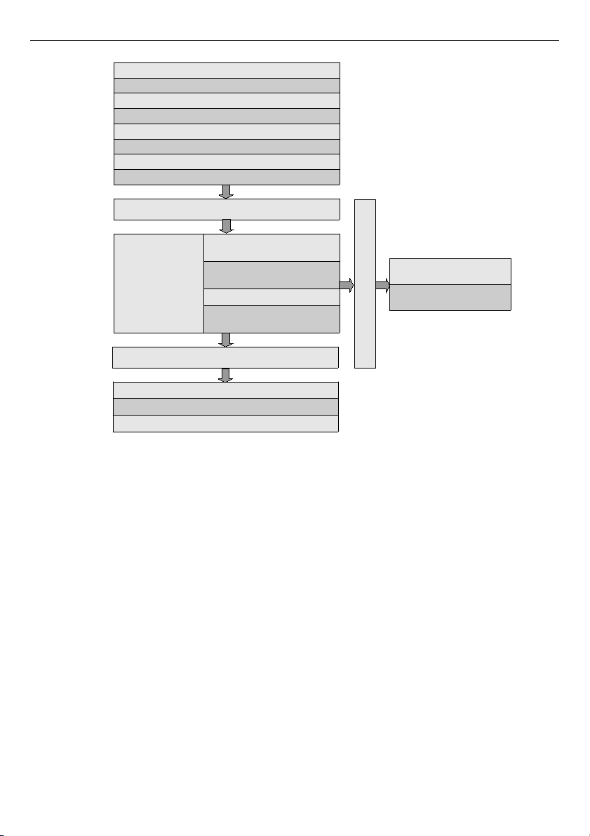
Fig. 2.1. Basic structure of the multichannel device
Process control with built-in outputs can be done with programmable hysteresis and
delays of the outputs control. It is possible to control (linearly or bistably) remote
modules. Controlling processes can drive built-in physical outputs or virtual outputs
which can be used as inputs to
logical channels
.
8
Build-in analog input
Buid-in binary input
External input (RS-485)
Profiles/timers
Controller
Mathematical & logical combination data
States of hardware & virtual outputs
Set point values
Display
Numeric, logical or text values
Charts & bars
Needles indicators
Grouping data
Interface
Build-in analog output
Build-in binary output
External output (RS-485)
Interface
Reading data via Ethernet
Reading data stored on the
flash drive
Interface
Page 9

User Manual For - CONTROLLER/DATA RECORDER MultiCon CMC-99/141
3. TECHNICAL DATA
Power supply voltage
(depending on version)
External Fuse (required)
Power consumption
85...
230
...260V AC/DC; 50 ÷ 60 Hz
or 19...24...50V DC; 16V...24...35V AC
T - type, max. 2 A
typically 15 VA; max. 20 VA
Display (depending on version) 3.5” or 5.7”, TFT color graphic display, 320 x 240
pixels, with LED backlight
Sensor power supply output 24V DC ± 5% / max. 200 mA,
Basic communication interfaces RS 485, 8N1/2, Modbus RTU, 1200 bit/s ÷ 115200 bit/s
USB Host port, USB Device port
Digital input 1 input 0/15..24V DC, galvanic isolation (low state:
0÷1V, high state:8÷24V)
power consumption: 7,5 mA / 24V,
isolation: 1min @ 500V DC.
Optional communication module* Second USB Host port
Serial RS-485 and RS-485/RS-232
Ethernet 10M RJ-45
Optional input modules* 4/8/16/24x Voltage (0÷10V) / Current (0÷20mA)**
16/24x NTC (0÷100k)/ Voltage (0÷10V)/
Current (0÷20mA)/ Digital (TTL,HTL)**
6x Isolated current (4÷20mA),
4/6x RTD (Pt100, Pt500, Pt1000, Cu50, Cu100)**
4/8x/12 TC (J, K, S, T, N, R, E, L(GOST), B, C**
8/16/24x Digital input**
3/5x Universal input**
2/4x Universal counter input**
2/4x Hourmeter module**
2/4x Flowmeter + 2/4x Current input**
2/4x Pulse input + 2/4x Current input**
Optional output modules*
4/6x Relay 5A/250V (cos ϕ = 1)**
8/12x Relay 1A/250V (cos ϕ = 1)**
8/16/24x SSR driver (10÷15V, up to 100mA per
output)**
2/4/6/8x IO Passive current output (4÷20mA)**
Protection level
USB interface on rear panel
USB interface from front
IP 65 (from front, after using waterproof frame)
IP 54 (from front, with transparent door)
IP 40 (from front, standard)
IP 20 (housing and connection clips)
IP 54 (from front, with transparent door)
IP 40 (from front, standard)
IP 20 (housing and connection clips)
Housing type
Housing material
panel
NORYL - GFN2S E1
9
Page 10
User Manual For - CONTROLLER/DATA RECORDER MultiCon CMC-99/141
Housing dimensions 96 x 96 x 100 mm (small housing - 3,5” Display)
or 144 x 144 x 100 mm (big housing - 5,7” Display)
Mounting hole 90.5 x 90.5 mm (small housing - 3,5” Display)
or 137 x 137 mm (big housing - 5,7” Display)
Assembly depth
Panel thickness
102 mm
max. 5 mm
Operating temperature
(depending on version)
0°C to +50°C
or -20°C to +50°C
Storage temperature
(depending on version)
-10°C to +70°C
or -20°C to +70°C
Humidity
Altitude
5 to 90% no condensation
up to 2000 meters above sea level
Screws tightening max. torque 0,5 Nm
Max. connection leads diameter 2,5 mm
2
Safety requirements according to: PN-EN 61010-1
installation category: II
pollution degree: 2
voltage in relation to ground: 300V AC
isolation resistance: >20MΩ
isolation strength between power supply and
input/output terminal: 1min. @ 2300V (see
Fig. 4.1
)
EMC PN-EN 61326-1
Weight
340g (only base, see
Fig. 4.8
)
* check the current list of measurement modules at producer's website
** see the full specification in the Appendices
4. DEVICE INSTALLATION
The unit has been designed and manufactured in a way assuring a high level of user
safety and resistance to interference occurring in a typical industrial environment. In order to
take full advantage of these characteristics installation of the unit must be conducted correctly
and according to the local regulations.
- Read the basic safety requirements on page 5 prior to starting the installation.
- Ensure that the power supply network voltage corresponds to the nominal
voltage stated on the unit’s identification label.
- The load must correspond to the requirements listed in the technical data.
- All installation works must be conducted with a disconnected power supply.
- Protecting the power supply connections against unauthorized persons must
be taken into consideration.
10
!
Page 11
User Manual For - CONTROLLER/DATA RECORDER MultiCon CMC-99/141
This is a class A unit. Class A equipment is suitable for use in all
establishments other than domestic and those directly connected to a low
voltage power supply network which supplies buildings used for domestic
purposes.
This is group 1 unit. Group 1 contains all equipment in the scope of this
standard which is not classified as group 2 equipment. Group 2 contains
all ISM RF equipment in which radio-frequency energy in the frequency
range 9 kHz to 400 GHz is intentionally generated and used or only used, in
the form of electromagnetic radiation, inductive and/or capacitive
coupling, for the treatment of material or inspection/analysis purposes.
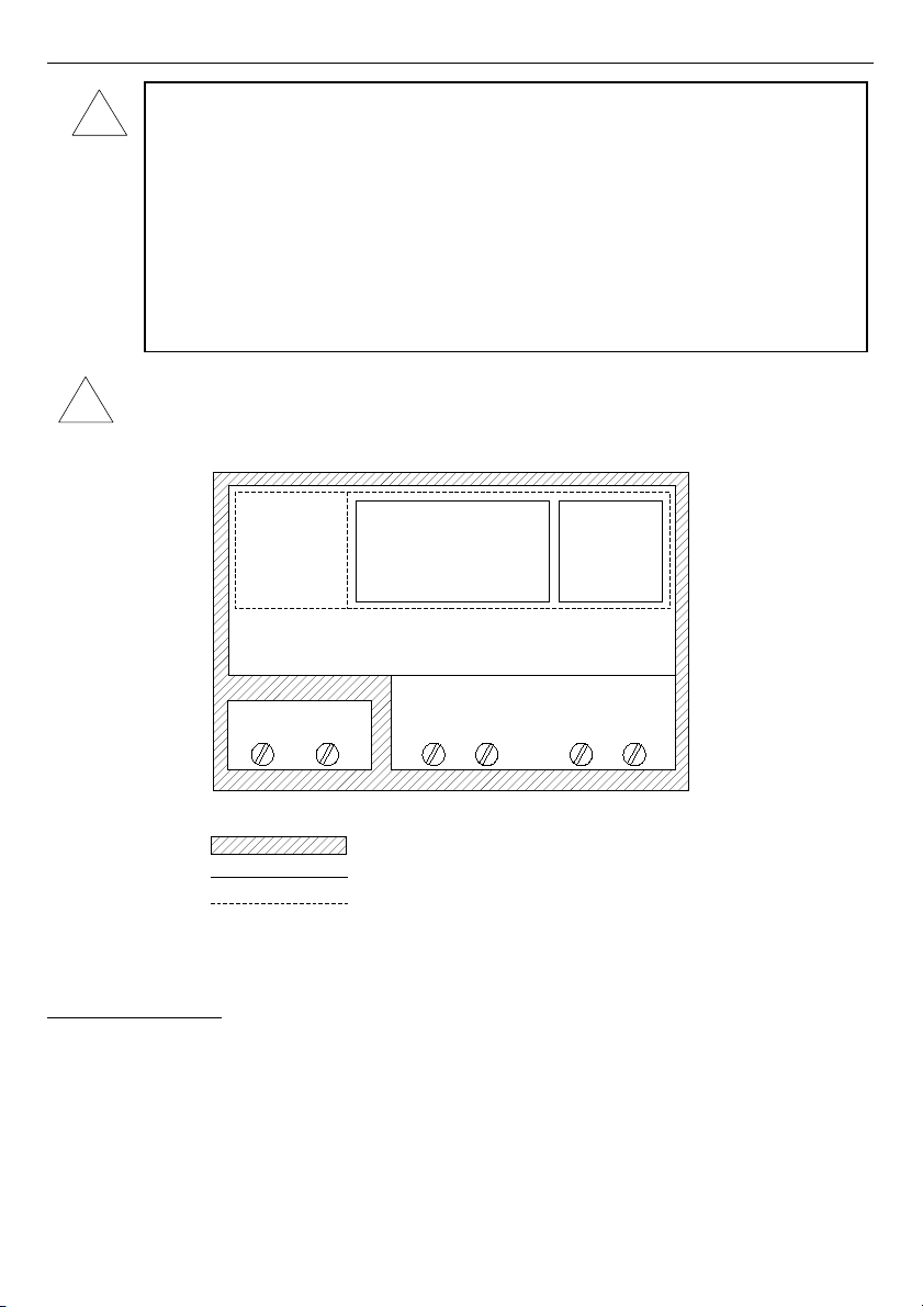
Carefully check that the isolation used with the unit (
Fig. 4.1
) meets the
expectations and if necessary use appropriate measures of over voltage protection.
Additionally, insure the appropriate air and surface insulation gaps when installing.
Fig. 4.1. Schematic diagram showing the isolation between individual circuits of the unit.
4.1. UNPACKING
After removing the unit from the protective packaging, check for transportation damage.
Any transportation damage must be immediately reported to the carrier. Also, write down the
unit serial number located on the housing and report the damage to the manufacturer.
Attached with the unit please find:
– assembly brackets - 2 pieces,
– pointer for touch screen,
– user’s manual for
MultiCon CMC-99/141
unit (device) in
pdf.
,
11
!
!
Internal circuits
External sensor
supply output
Measurement inputs
RS 485
interface
and
digital input
Isolation strength 1min @ 2300V AC
Isolation strength 1min @ 500V AC
No isolation
Outputs circuits
Power supply
Page 12
User Manual For - CONTROLLER/DATA RECORDER MultiCon CMC-99/141
4.2. ASSEMBLY
- The unit is designed for mounting inside housings (control panel, switchboard)
insuring appropriate protection against surges and interference. Metal
housings must be connected to ground in a way that complies with the
governing regulations.
- Disconnect the power supply prior to starting assembly.
- Check the connections are wired correctly prior to switching the unit on.
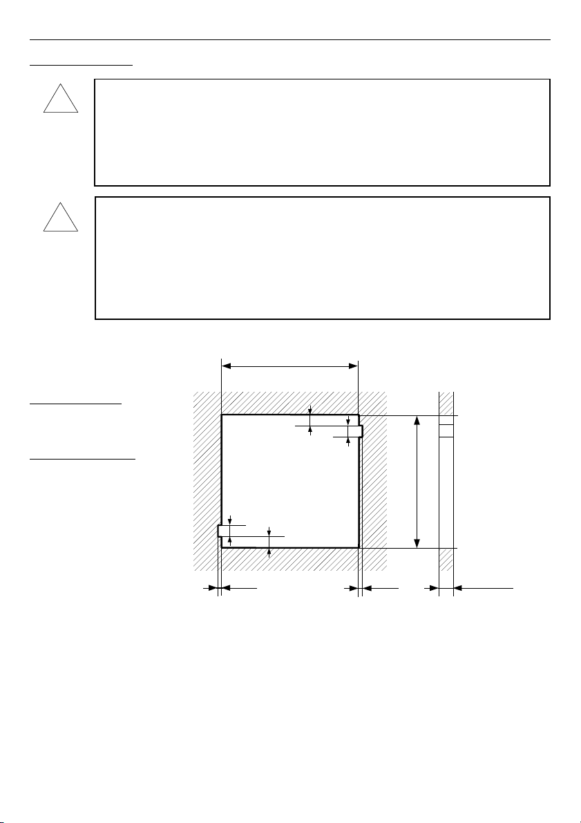
- In order to install the unit, a mounting hole must be prepared according to
Fig. 4.2
. The thickness of the material of which the panel is made must not
exceed 5mm. W hen preparing the mounting hole take the grooves for catches
located on both sides of the housing into consideration (
Fig. 4.2
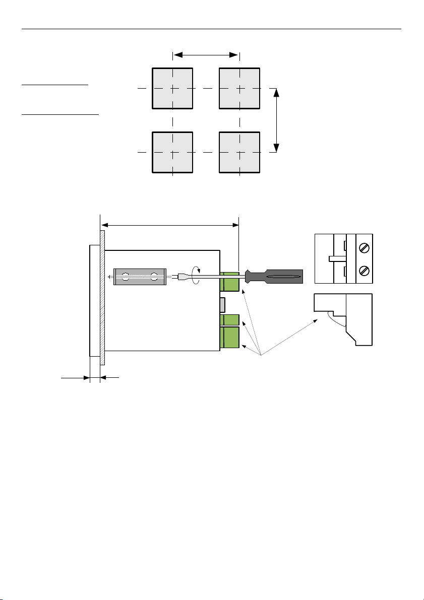
). Place the
unit in the mounting hole inserting it from the front side of the panel, and then
fix it using the brackets (
Fig. 4.4
). The minimum distances between the centre
points of multiple units - due to the thermal and mechanical conditions of
operation - are shown on
Fig. 4.3
.
96 x 96 housing:
H, W = 90.5 mm
h = 16 mm
144 x 144 housing:
H, W = 137 mm
h= 38.5 mm
Fig. 4.2. Mounting hole dimensions
12
W
h
8 mm
8 mm
h
1 mm
max. 5 mm
H
1 mm
!
!
Page 13
User Manual For - CONTROLLER/DATA RECORDER MultiCon CMC-99/141
96 x 96 housing:
H, W = 115 mm
144 x 144 housing:
H, W = 165 mm
Fig. 4.3. Minimum distances when assembly of a number of units
Fig. 4.4. Installing of brackets
13
98 mm
8 mm
removable terminals
W
H
Page 14
User Manual For - CONTROLLER/DATA RECORDER MultiCon CMC-99/141
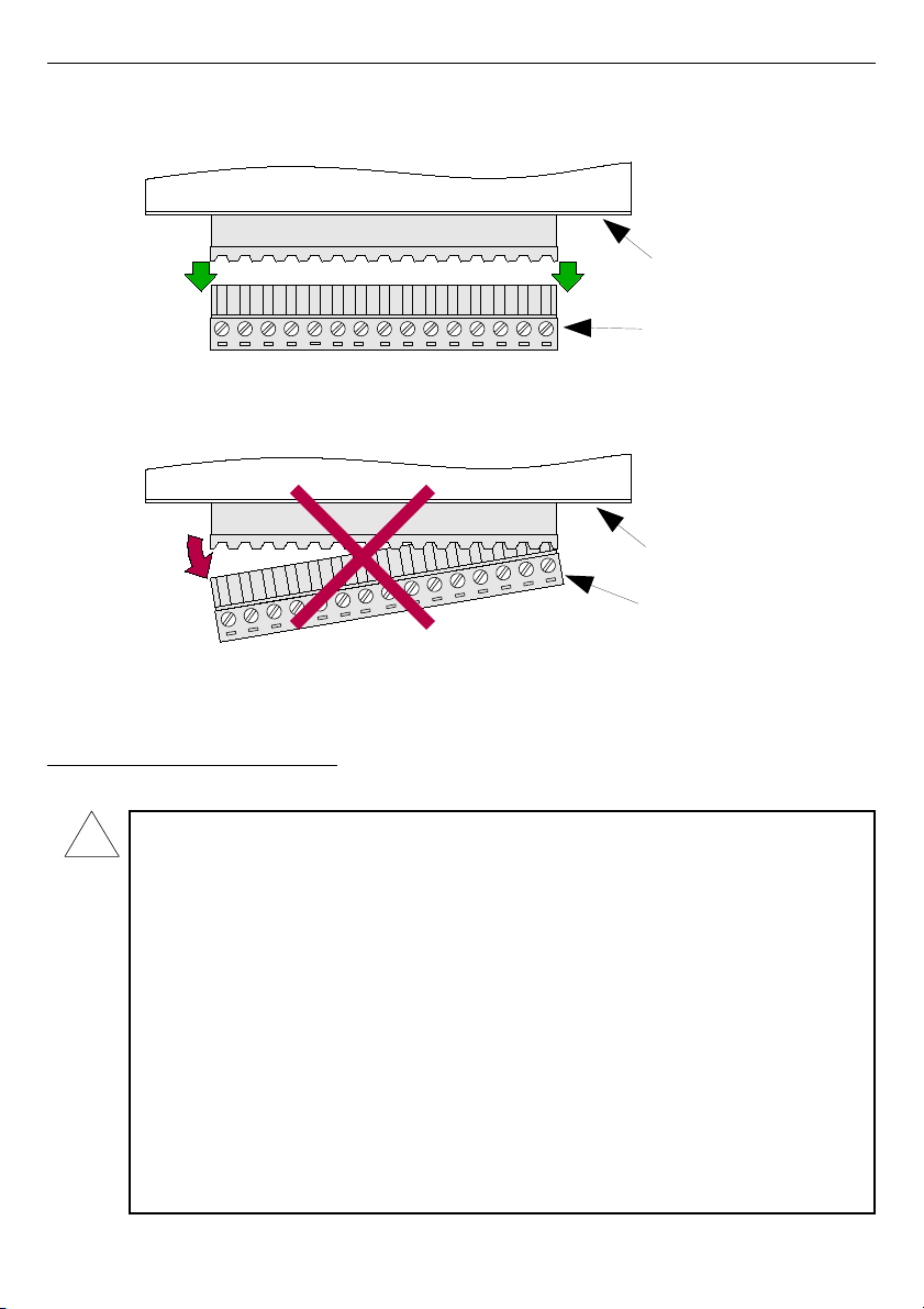
To avoid connectors slots destruction use the method shown on
Fig. 4.5
Fig. 4.5. Connectors removing method
4.3. CONNECTION METHOD
Caution
- Installation should be conducted by qualified personnel. During installation all
available safety requirements should be considered. The fitter is responsible for
executing the installation according to this manual, local safety and EMC
regulations.
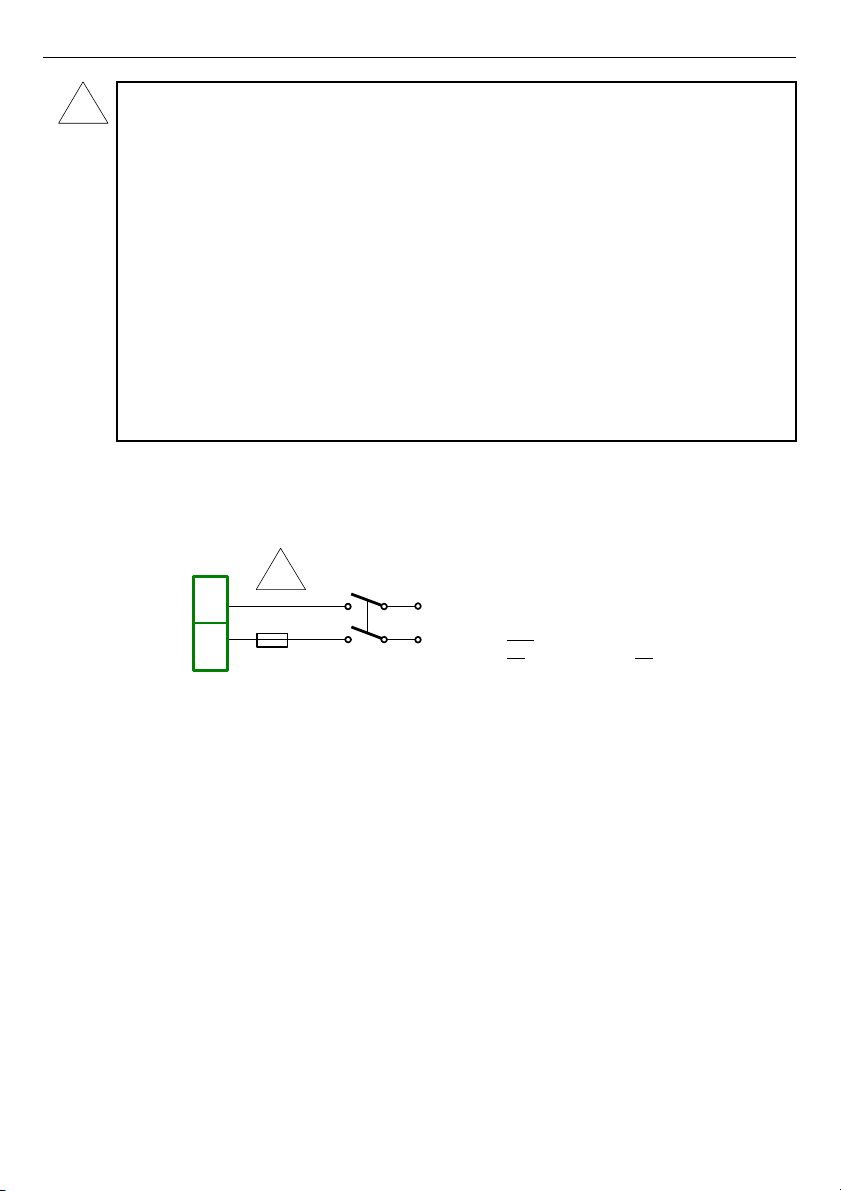
- The unit is not equipped with an internal fuse or power supply circuit breaker.
Because of this an external time-delay cut-out fuse with a small nominal current
value must be used (recommended bipolar, max. 2A) and a power supply circuitbreaker located near the unit (
Fig. 4.6
). In the case of using a monopolar fuse it
must be mounted on the active wire (L).
- The power supply network cable diameter must be selected in such a way that in
the case of a short circuit of the cable from the side of the unit the cable shall be
protected against destruction with an electrical installation fuse.
- Wiring must meet appropriate standards and local regulations and laws.
- In order to secure against accidental short circuit the connection cables must be
terminated with appropriate insulated cable tips.
14
back side
of device
connector
GOOD
back side
of device
connector
WRONG
!
Page 15
User Manual For - CONTROLLER/DATA RECORDER MultiCon CMC-99/141
- Tighten the clamping screws. The recommended tightening torque is 0.5 Nm.
Loose screws can cause fire or defective operation. Over tightening can lead to
damaging the connections inside the units and breaking the thread.
- In the case of the unit being fitted with separable clamps they should be inserted
into appropriate connectors in the unit, even if they are not used for any
connections.
- Unused terminals (marked as n.c.) must not be used for connecting any
connecting cables (e.g. as bridges), because this can cause damage to the
equipment or electric shock.
- If the unit is equipped with housing, covers and sealing to protecting against
water intrusion, pay special attention to their correct tightening or clamping. In the
case of any doubt consider using additional preventive measures (covers, roofing,
seals, etc.). Carelessly executed assembly can increase the risk of electric shock.
- After the installation is completed do not touch the unit’s connections when it is
switched on, because it carries the risk of electrical shock.
Due to possible significant interference in industrial installations appropriate measures
assuring correct operation of the unit must be applied. To avoid the unit of improper
indications keep recommendations listed below.
Depending on version:
85...230...260V AC/DC or
19...24...50V DC; 16...24...35V AC
Fig. 4.6. Connection of power supply
• Avoid running signal cables and transmission cables together with power supply cables
and cables controlling inductive loads (e.g. contactors). Such cables should cross at a
right angle.
• Contactor coils and inductive loads should be equipped with interference protection
systems, e.g. RC-type.
• Use of screened signal cables is recommended. Signal cable screens should be
connected to the earthing only at one of the ends of the screened cable.
• In the case of magnetically induced interference the use of twisted pair signal cables is
recommended. Twisted pair (best if shielded) must be used with RS-485 serial
transmission connections.
• In the case of measurement or control signals are longer than 30m or go outside of the
building then additional safety circuits are required.
• In the case of interference from the power supply side the use of appropriate interference
filters is recommended. Bear in mind that the connection between the filter and the unit
should be as short as possible and the metal housing of the filter must be connected to
the earth with the largest possible surface. The cables connected to the filter output must
not be run with cables with interference (e.g. circuits controlling relays or contactors).
15
!
!
FUSE
N
L
N
L
1
2
Page 16
User Manual For - CONTROLLER/DATA RECORDER MultiCon CMC-99/141
Connections of power supply voltage and measurement signals are executed using the
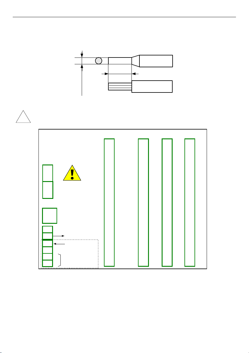
screw connections on the back of the unit’s housing.
Fig. 4.7. Method of cable isolation replacing and cable terminals dimensions
All connections must be made while power supply is disconnected !
Fig. 4.8. Terminals description
The basic performance of the device (see
Fig. 4.8
) contains only the extreme left
terminals:
– Power supply,
– SERVICE,
– Sensor supply output +24V DC Imax=200mA,
– Digital input 0V...15...24V DC (low state: 0÷1V, high state:8÷24V)
– Interface RS-485,
16
!
5-6 mm
max. 1.5 mm
Slot D
Power supply
(depending on version)
1
2
Slot B
8
5
6
7
3
4
Slot A
Slot C
+24V DC ±5%
Imax. = 200mA
digital input
0/15..24V DC
RS-485
GND
GND
A+
B-
isolated
SERVICE
Page 17
User Manual For - CONTROLLER/DATA RECORDER MultiCon CMC-99/141
– If the
UN3
or
UN5
module is installed, the +24V DC output is available only in
devices equipped with
PS42
power supply module. In other cases there is
no +24V DC output
available and these terminals remain disconnected.
Depending on customer's needs, the basic version of the device can be upgraded with up to:
– three I / O modules (installed in a place designated as
Slot A, Slot B, Slot C
),
– advanced communication module (additional serial, USB and Ethernet interfaces
installed in
Slot D
).
According to the order these terminals can look different than shown in
Fig. 4.8
or be not
present. Terminals and connections of available modules are shown in
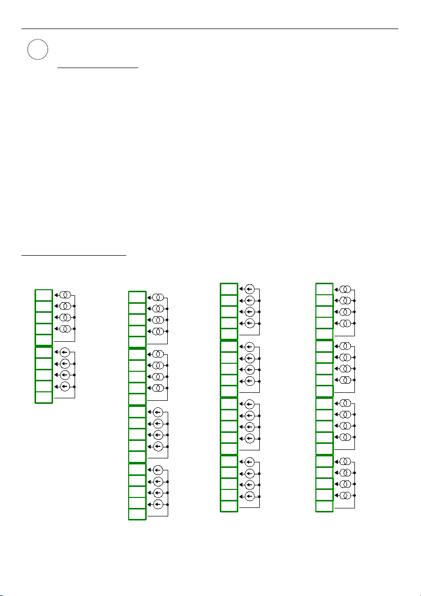
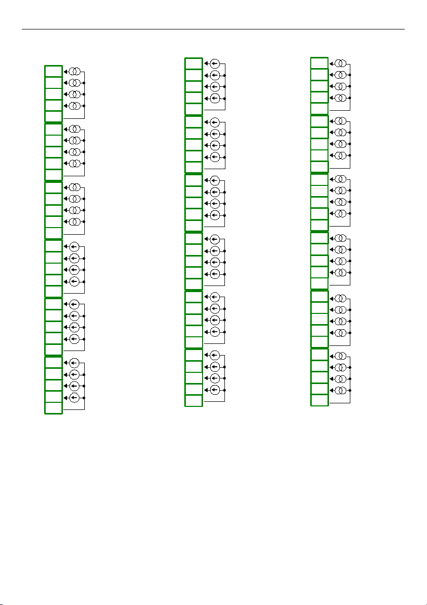
Fig. 4.9÷Fig. 4.21
in
Section 4.3.1.
.
Shown below is an example of a configuration of the installed modules:
– base,
– Slot A - UI8 module (8 current input & 8 voltage input),
– Slot B - RT4 module (4 RTD input),
– Slot C - R81 module (8 relay output 1A/250V),
– Slot D - ACM module (additional serial, USB and Ethernet interfaces).
4.3.1. Available modules
Fig. 4.9. Voltage and current input modules
17
i
U16
16 voltage inputs
n08
n09
n10
n11
n12
n04
n05
n06
n07
n01
n02
n03
n20
n16
n17
n18
n19
n13
n14
n15
GND
IN9
IN10
IN11
IN12
4 x 0-10V
GND
IN13
IN14
IN15
IN16
4 x 0-10V
GND
IN1
IN2
IN3
IN4
4 x 0-10V
GND
IN5
IN6
IN7
IN8
4 x 0-10V
I16
16 current inputs
n08
n09
n10
n11
n12
n04
n05
n06
n07
n01
n02
n03
n20
n16
n17
n18
n19
n13
n14
n15
GND
IN1
IN2
IN3
IN4
4 x 0-20mA
GND
IN5
IN6
IN7
IN8
4 x 0-20mA
GND
IN9
IN10
IN11
IN12
4 x 0-20mA
GND
IN13
IN14
IN15
IN16
4 x 0-20mA
UI4
4 current
+ 4 voltage inputs
n08
n09
n10
n04
n05
n06
n07
n01
n02
n03
GND
IN1
IN2
IN3
IN4
4 x 0-20mA
GND
IN5
IN6
IN7
IN8
4 x 0-10V
UI8
8 current
+ 8 voltage inputs
n08
n09
n10
n11
n12
n04
n05
n06
n07
n01
n02
n03
n20
n16
n17
n18
n19
n13
n14
n15
GND
IN1
IN2
IN3
IN4
4 x 0-20mA
GND
IN5
IN6
IN7
IN8
4 x 0-20mA
GND
IN9
IN10
IN11
IN12
4 x 0-10V
GND
IN13
IN14
IN15
IN16
4 x 0-10V
Page 18
User Manual For - CONTROLLER/DATA RECORDER MultiCon CMC-99/141
Fig. 4.10. Voltage and current input modules contd.
18
UI12
12 current
+ 12 voltage inputs
n08
n09
n10
n11
n12
n04
n05
n06
n07
n01
n02
n03
n20
n16
n17
n18
n19
n13
n14
n15
n21
n22
n30
n26
n27
n28
n29
n23
n24
n25
GND
IN1
IN2
IN3
IN4
4 x 0-20mA
GND
IN5
IN6
IN7
IN8
4 x 0-20mA
GND
IN21
IN22
IN23
IN24
4 x 0-10V
GND
IN13
IN14
IN15
IN16
4 x 0-10V
GND
IN17
IN18
IN19
IN20
4 x 0-10V
GND
IN9
IN10
IN11
IN12
4 x 0-20mA
U24
24 voltage inputs
n08
n09
n10
n11
n12
n04
n05
n06
n07
n01
n02
n03
n20
n16
n17
n18
n19
n13
n14
n15
n11
n12
n20
n16
n17
n18
n19
n13
n14
n15
n21
n22
n30
n26
n27
n28
n29
n23
n24
n25
GND
IN9
IN10
IN11
IN12
4 x 0-10V
GND
IN13
IN14
IN15
IN16
4 x 0-10V
GND
IN1
IN2
IN3
IN4
4 x 0-10V
GND
IN5
IN6
IN7
IN8
4 x 0-10V
GND
IN17
IN18
IN19
IN20
4 x 0-10V
GND
IN21
IN22
IN23
IN24
4 x 0-10V
I24
24 current inputs
n08
n09
n10
n11
n12
n04
n05
n06
n07
n01
n02
n03
n20
n16
n17
n18
n19
n13
n14
n15
n21
n22
n30
n26
n27
n28
n29
n23
n24
n25
GND
IN1
IN2
IN3
IN4
4 x 0-20mA
GND
IN5
IN6
IN7
IN8
4 x 0-20mA
GND
IN9
IN10
IN11
IN12
4 x 0-20mA
GND
IN13
IN14
IN15
IN16
4 x 0-20mA
GND
IN17
IN18
IN19
IN20
4 x 0-20mA
GND
IN21
IN22
IN23
IN24
4 x 0-20mA
Page 19
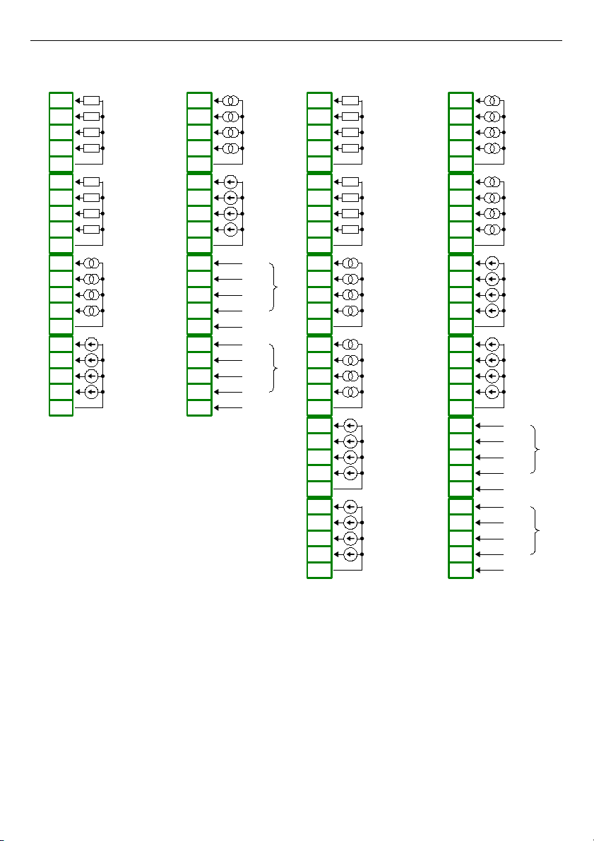
User Manual For - CONTROLLER/DATA RECORDER MultiCon CMC-99/141
Fig. 4.11. Mixed input modules
19
n01
n02
n03
n04
n05
n06
n07
n08
n09
n10
n11
n12
n13
n14
n15
n16
n17
n18
n19
n20
GND
IN9
IN10
IN11
IN12
4 x 0-20mA
GND
IN5
IN6
IN8
IN7
4 x 0 - 100kΩ
IN1
IN2
IN4
IN3
GND
4 x 0 - 100kΩ
UI4N8
8 resistance
+ 4 current and 4 voltage inputs
GND
IN13
IN14
IN15
IN16
4 x 0-10V
n01
n02
n03
n04
n05
n06
n07
n08
n09
n10
n11
n12
n13
n14
n15
n16
n17
n18
n19
n20
UI4D8
4 current and 4 voltage
+ 8 digital inputs
GND
IN1
IN2
IN3
IN4
4 x 0-20mA
GND
IN5
IN6
IN7
IN8
4 x 0-10V
COM 9-12
IN9
IN10
IN11
IN12
IN17
COM 13-16
IN13
IN14
IN15
IN16
IN18
n01
n02
n03
n04
n05
n06
n07
n08
n09
n10
n11
n12
n13
n14
n15
n16
n17
n18
n19
n20
n21
n22
n23
n24
n25
n26
n27
n28
n29
n30
GND
IN9
IN10
IN11
IN12
4 x 0-20mA
GND
IN13
IN14
IN15
IN16
4 x 0-20mA
GND
IN5
IN6
IN8
IN7
4 x 0 - 100kΩ
IN1
IN2
IN4
IN3
GND
4 x 0 - 100kΩ
UI8N8
8 resistance
+ 8 current and voltage inputs
GND
IN17
IN18
IN19
IN20
4 x 0-10V
GND
IN21
IN22
IN23
IN24
4 x 0-10V
n01
n02
n03
n04
n05
n06
n07
n08
n09
n10
n11
n12
n13
n14
n15
n16
n17
n18
n19
n20
n21
n22
n23
n24
n25
n26
n27
n28
n29
n30
GND
IN1
IN2
IN3
IN4
4 x 0-20mA
GND
IN5
IN6
IN7
IN8
4 x 0-20mA
UI8D8
8 current and voltage
+ 8 digital inputs
GND
IN9
IN10
IN11
IN12
4 x 0-10V
GND
IN13
IN14
IN15
IN16
4 x 0-10V
COM 17-20
IN17
IN18
IN19
IN20
IN25
COM 21-24
IN21
IN22
IN23
IN24
IN26
Page 20
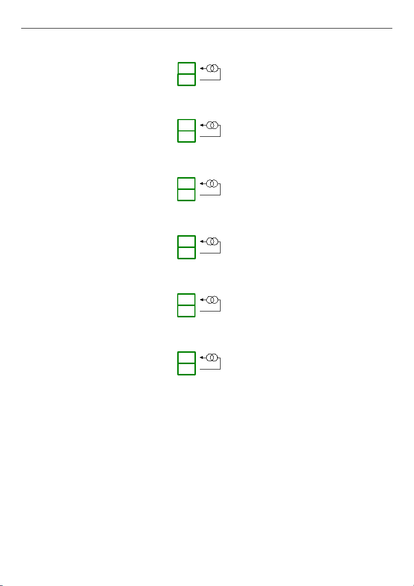
User Manual For - CONTROLLER/DATA RECORDER MultiCon CMC-99/141
Fig. 4.12.Isolated current input modules
20
IS6
6 isolated current input
IN 1
n01
n02
n03
n04
n05
n06
n07
n08
n09
n10
n11
n12
IN 2
IN 3
IN 4
IN 5
IN 6
Page 21
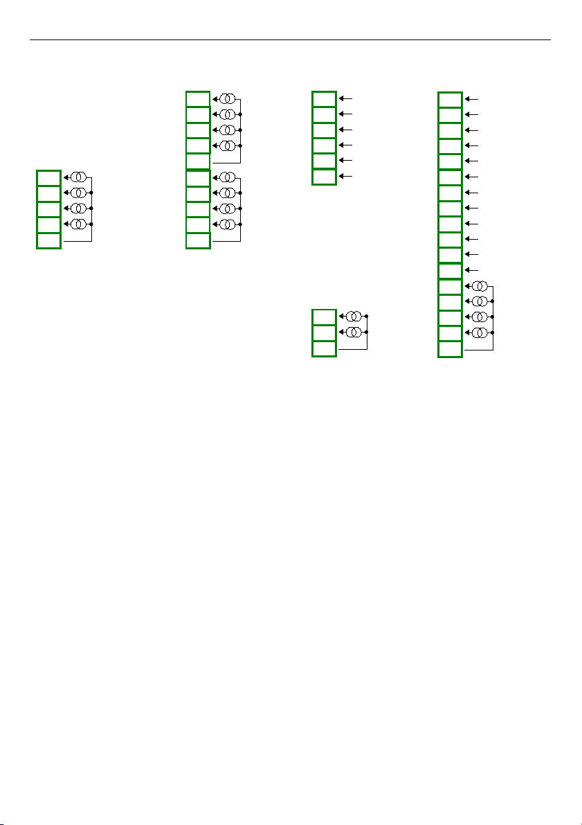
User Manual For - CONTROLLER/DATA RECORDER MultiCon CMC-99/141
Fig. 4.13. Flowmeter modules
21
FI4
4 flowmeter inputs
+ 4 current inputs
n08
n09
n10
n04
n05
n06
n07
n01
n02
n03
GND
IN1
IN2
IN3
IN4
4 x 0-20mA
(flowmeters)
GND
IN5
IN6
IN7
IN8
4 x 0-20mA
FI2
2 flowmeter inputs
+ 2 current inputse
n03
n04
n05
n01
n02
GND
IN1
IN2
IN3
IN4
2 x 0-20mA
2 x 0-20mA
(flowmeters)
FT2
2 pulse inputs
+ 2 current inputs
n07
n08
n09
n04
n05
n01
n02
n03
n04
n05
n01
n02
n03
n06
GND
IN3
IN4
2 x 0-20mA
COM2
Inp22
Inp21
COM1
Inp12
Inp11
FT4
4 pulse inputs
+ 4 current inputs
n15
n16
n17
n04
n05
n13
n14
n01
n02
n03
n04
n05
n01
n02
n03
n06
n10
n11
n07
n08
n09
n12
GND
IN5
IN6
IN7
IN8
4 x 0-20mA
COM4
Inp42
Inp41
COM3
Inp32
Inp31
COM2
Inp22
Inp21
COM1
Inp12
Inp11
Page 22
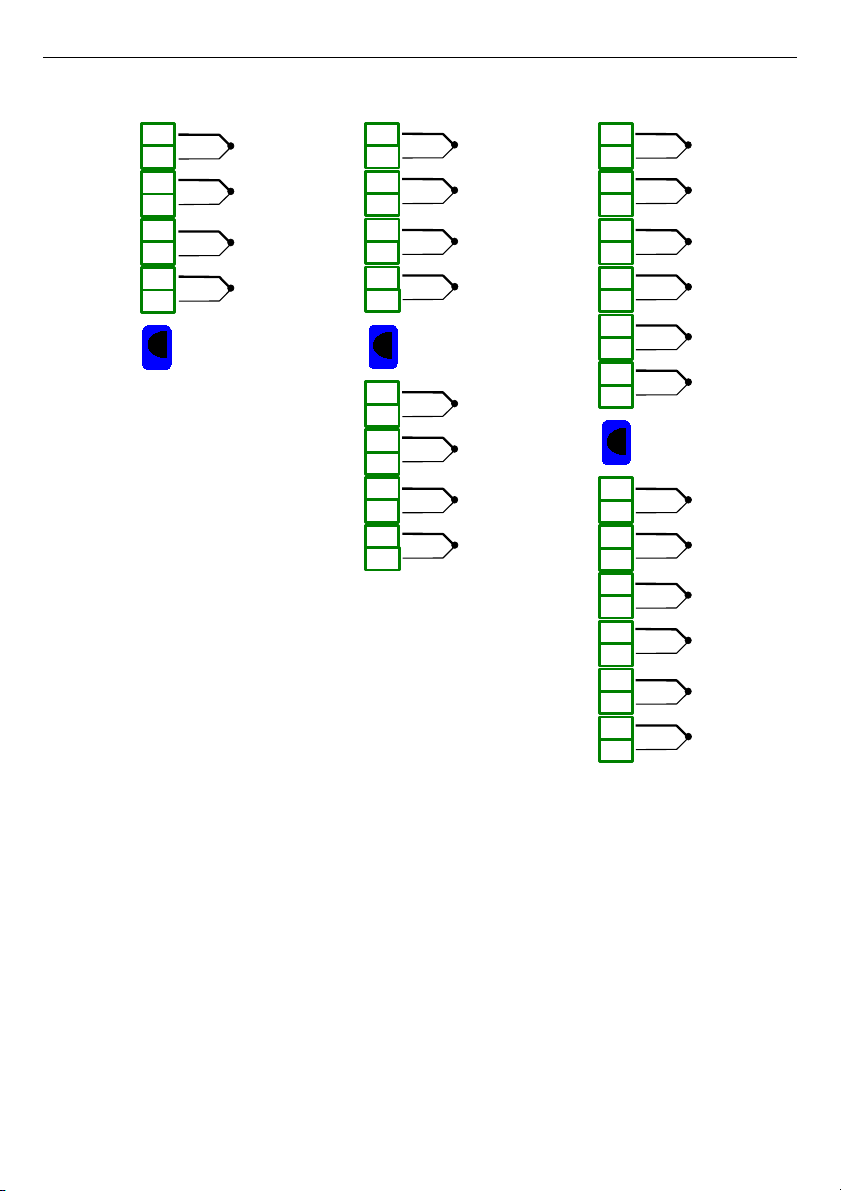
User Manual For - CONTROLLER/DATA RECORDER MultiCon CMC-99/141
Fig. 4.14. TC input modules
22
TC8
8 thermocouple inputs
n06
n07
n08
n04
n05
n01
n02
n03
n14
n15
n16
n12
n13
n09
n10
n11
IN1
+
-
IN2
+
-
IN3
+
-
IN4
+
-
IN5
+
-
IN6
+
-
IN7
+
-
IN8
+
-
IN_T
TC4
4 thermocouple inputs
n06
n07
n08
n04
n05
n01
n02
n03
IN1
+
-
IN2
+
-
IN3
+
-
IN4
+
-
IN_T
TC12
12 thermocouple inputs
n06
n07
n08
n04
n05
n01
n02
n03
n14
n15
n16
n12
n13
n09
n10
n11
IN1
+
-
IN2
+
-
IN3
+
-
IN4
+
-
IN5
+
-
IN6
+
-
IN7
+
-
IN8
+
-
IN_T
n22
n23
n24
n20
n21
n17
n18
n19
IN9
+
-
IN10
+
-
IN11
+
-
IN12
+
-
Page 23
User Manual For - CONTROLLER/DATA RECORDER MultiCon CMC-99/141
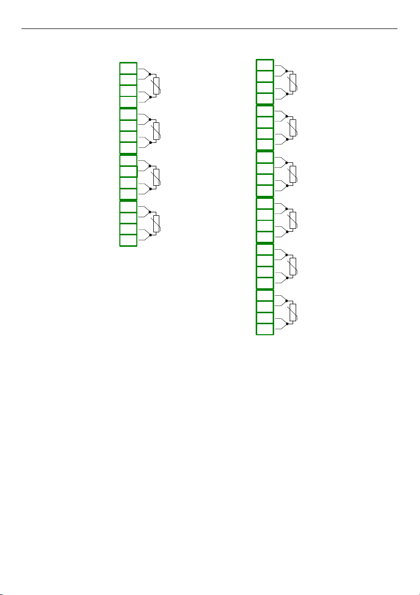
Fig. 4.15. RTD input modules
23
RT4
4 RTD inputs
n08
n09
n10
n11
n12
n04
n05
n06
n07
n01
n02
n03
n16
n13
n14
n15
IN1IN2IN3IN4
RT6
6 RTD inputs
IN1IN2IN3
IN4IN5
n08
n09
n10
n11
n12
n04
n05
n06
n07
n01
n02
n03
n16
n13
n14
n15
n20
n17
n18
n19
n24
n21
n22
n23
IN6
Page 24
User Manual For - CONTROLLER/DATA RECORDER MultiCon CMC-99/141
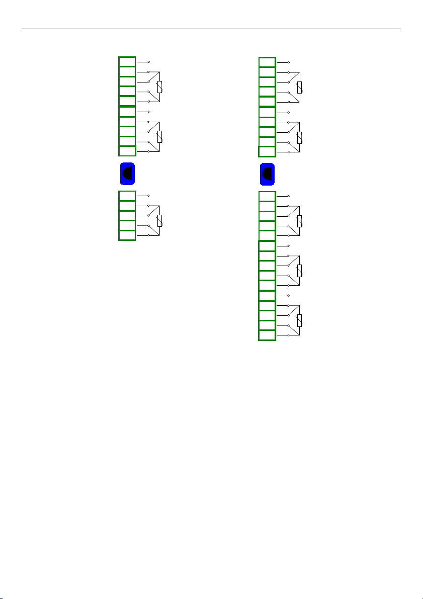
Fig. 4.16. Universal input modules
24
UN3
3 universal inputs
n08
n09
n10
n11
n12
n04
n05
n06
n07
n01
n02
n03
n13
n14
n15
V, mA
+
+
-
TC, mV
RTD
IN1
+
+
-
TC, mV
RTD
IN2
+
+
-
TC, mV
RTD
IN3
V, mA
V, mA
IN_T
UN5
5 universal inputs
n08
n09
n10
n11
n12
n04
n05
n06
n07
n01
n02
n03
n13
n14
n15
V, mA
+
+
-
TC, mV
RTD
IN1
+
+
-
TC, mV
RTD
IN2
+
+
-
TC, mV
RTD
IN3
V, mA
V, mA
n16
n17
n18
n19
n20
+
+
-
TC, mV
RTD
IN4
V, mA
n21
n22
n23
n24
n25
+
+
-
TC, mV
RTD
IN5
V, mA
IN_T
Page 25
User Manual For - CONTROLLER/DATA RECORDER MultiCon CMC-99/141
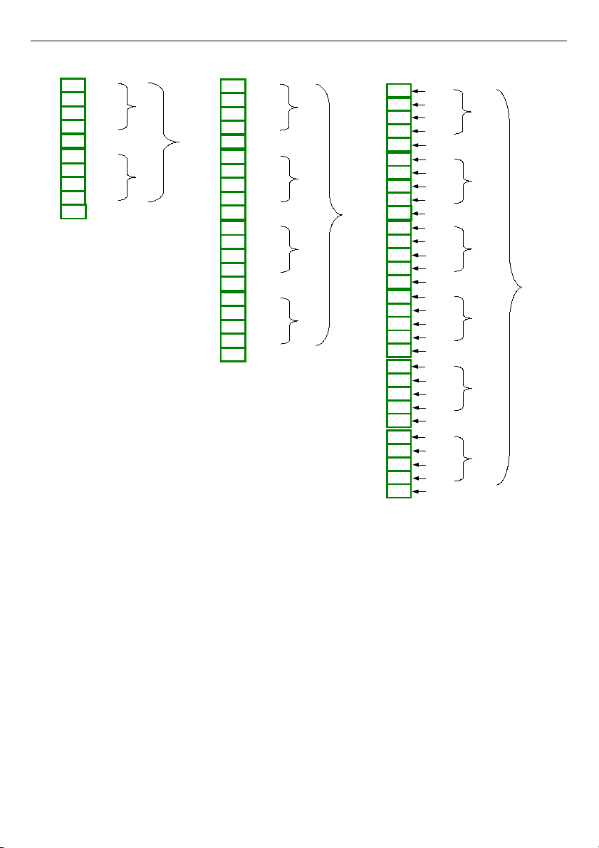
Fig. 4.17. Digital input modules
25
D16
16 Digital inputs
n08
n09
n10
n11
n12
n04
n05
n06
n07
n01
n02
n03
n20
n16
n17
n18
n19
n13
n14
n15
IN3
IN1
IN2
IN4
COM 1-4
IN5
IN6
IN12
IN11
IN9
COM 9-12
COM 13-16
IN15
IN13
IN14
IN16
IN7
IN10
IN8
COM 5-8
IN18
IN19
IN20
IN21
IN17
D8
8 Digital inputs
IN3
IN1
IN2
IN4
COM 1-4
IN5
IN6
IN7
IN8
COM 5-8
n08
n09
n10
n04
n05
n06
n07
n01
n02
n03
IN9
IN10
IN11
D24
24 Digital inputs
n08
n09
n10
n11
n12
n04
n05
n06
n07
n01
n02
n03
n20
n16
n17
n18
n19
n13
n14
n15
IN3
IN1
IN2
IN4
COM 1-4
IN5
IN6
IN12
IN11
IN9
COM 9-12
COM 13-16
IN15
IN13
IN14
IN16
IN7
IN10
IN8
COM 5-8
IN26
IN27
IN28
IN31
IN25
n25
n21
n22
n23
n24
COM 17-20
IN19
IN17
IN18
IN20
n30
n26
n27
n28
n29
COM 21-24
IN23
IN21
IN22
IN24
IN29
IN30
Page 26
User Manual For - CONTROLLER/DATA RECORDER MultiCon CMC-99/141
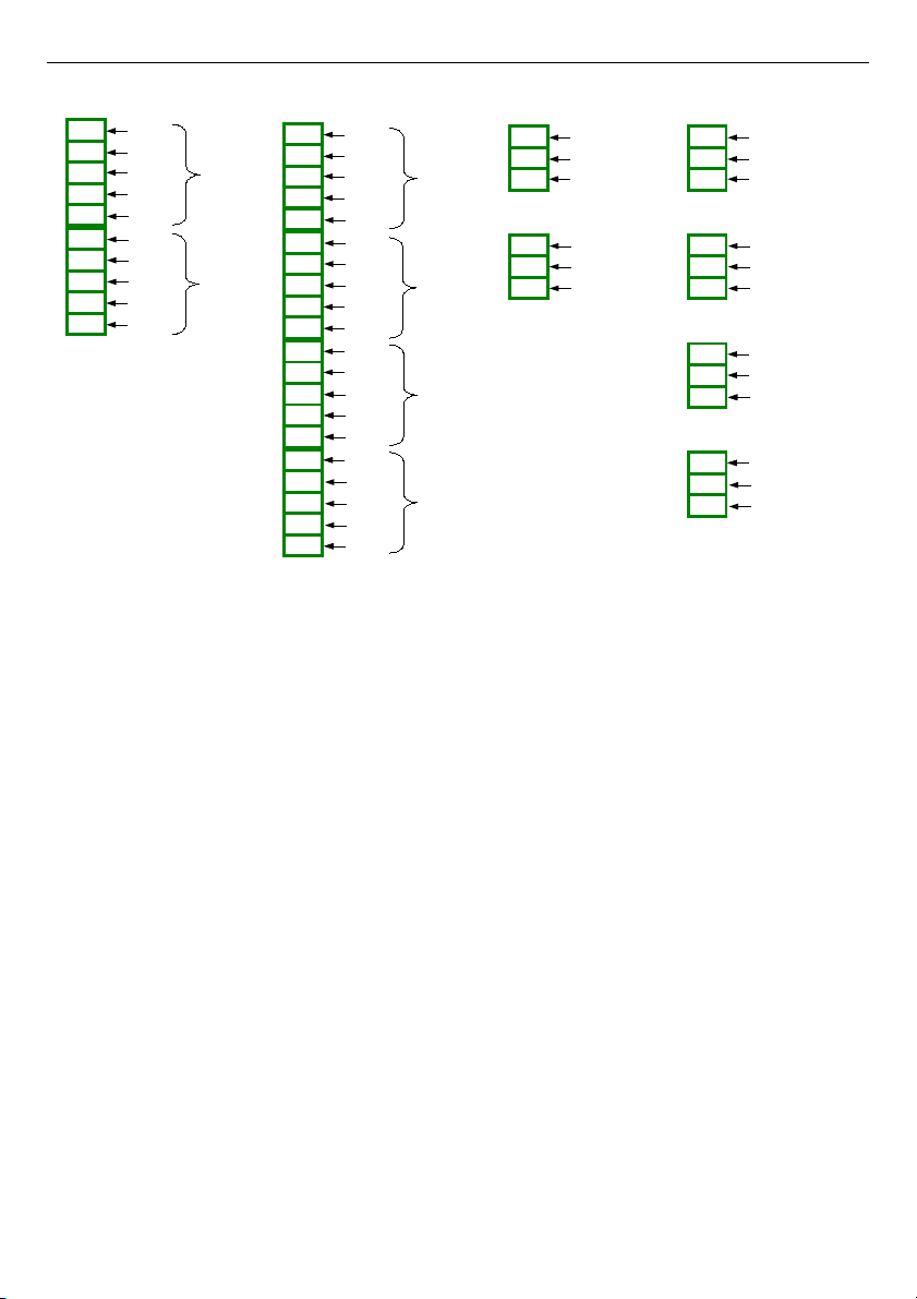
Fig. 4.18. Universal counters and hourmeters modules
26
CP4
4 universal counters
n08
n09
n10
n11
n12
n04
n05
n06
n07
n01
n02
n03
n20
n16
n17
n18
n19
n13
n14
n15
Prg1
Inp11
Inp12
Res1
COM1
Counter 1
Counter 2
Counter 3
Counter 4
Prg2
Inp21
Inp22
Res2
COM2
Prg3
Inp31
Inp32
Res3
COM3
Prg4
Inp41
Inp42
Res4
COM4
HM4
4 hourmeters
n06
n07
n08
n04
n05
n01
n02
n03
n10
n11
n12
n09
COM 1
START/STOP 1
PRG 1
COM 2
START/STOP 2
PRG 2
COM 3
START/STOP 3
PRG 3
COM 4
START/STOP 4
PRG 4
CP2
2 universal counters
n08
n09
n10
n04
n05
n06
n07
n01
n02
n03
Prg1
Inp11
Inp12
Res1
COM1
Counter 1
Counter 2
Prg2
Inp21
Inp22
Res2
COM2
HM2
2 hourmeters
n08
n04
n05
n01
n02
n03
COM 1
START/STOP 1
PRG 1
COM 2
START/STOP 2
PRG 2
Page 27
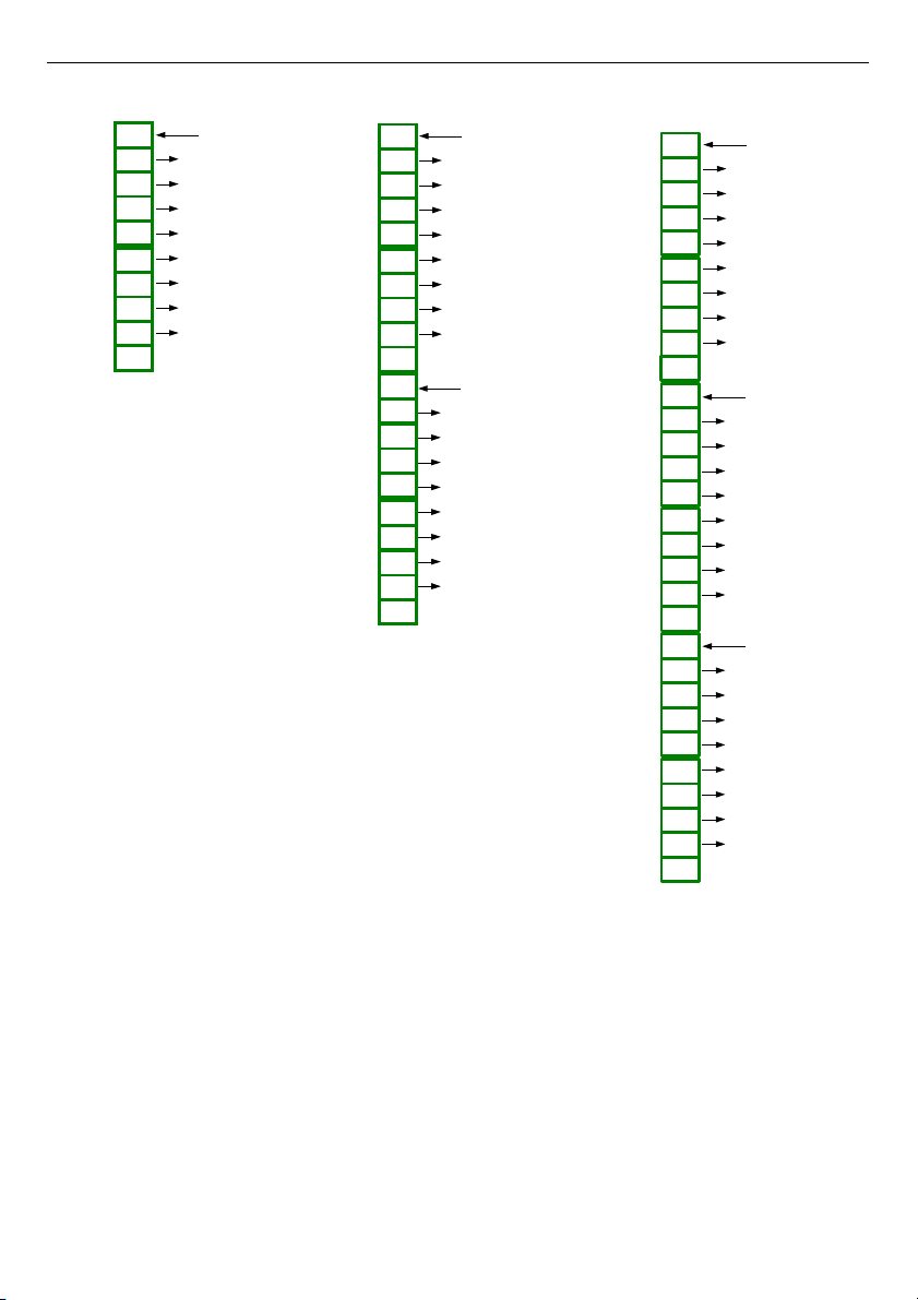
User Manual For - CONTROLLER/DATA RECORDER MultiCon CMC-99/141
Fig. 4.19. SSR output modules
27
S8
8 SSR outputs
OUT1
+10..24V DC
OUT2
OUT3
OUT4
OUT5
OUT6
OUT7
OUT8
GND
n01
n02
n03
n04
n05
n06
n07
n08
n09
n10
S16
16 SSR outputs
OUT1
+10..24V DC
OUT2
OUT3
OUT4
OUT5
OUT6
OUT7
OUT8
GND
OUT9
+10..24V DC
OUT10
OUT11
OUT12
OUT13
OUT14
OUT15
OUT16
GND
n01
n02
n03
n04
n05
n06
n07
n08
n09
n10
n11
n12
n13
n14
n15
n16
n17
n18
n19
n20
S24
24 SSR outputs
n08
n09
n10
n11
n12
n04
n05
n06
n07
n01
n02
n03
n20
n16
n17
n18
n19
n13
n14
n15
n21
n22
n30
n26
n27
n28
n29
n23
n24
n25
OUT1
+10..24V DC
OUT2
OUT3
OUT4
OUT5
OUT6
OUT7
OUT8
GND
OUT9
+10..24V DC
OUT10
OUT11
OUT12
OUT13
OUT14
OUT15
OUT16
GND
OUT17
+10..24V DC
OUT18
OUT19
OUT20
OUT21
OUT22
OUT23
OUT24
GND
Page 28
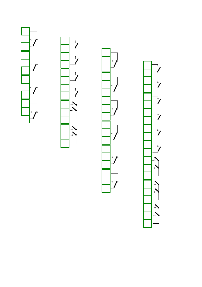
User Manual For - CONTROLLER/DATA RECORDER MultiCon CMC-99/141
Fig. 4.20. Relay output modules
28
R121
12 relay outputs 1A/250V
n01
n02
n03
n04
n05
n06
n07
n08
n13
n14
n15
n16
n17
n18
n09
n10
n11
n12
n19
n20
n21
OUT1
OUT2
OUT3
OUT4
OUT5
OUT6
OUT9
OUT10
OUT7
OUT8
OUT11
OUT12
R65
6 relay outputs 5A/250V
n01
n02
n03
n04
n05
n06
n07
n08
n09
n10
n11
n12
n13
n14
n15
n16
n17
n18
OUT1
OUT2
OUT3
OUT4
OUT5
OUT6
R81
8 relay outputs 1A/250V
n08
n09
n10
n11
n12
n04
n05
n06
n07
n01
n02
n03
n13
n14
OUT2
OUT1
OUT4
OUT3
OUT5
OUT6
OUT7
OUT8
R45
4 relay outputs 5A/250V
n06
n07
n08
n09
n10
n04
n05
n01
n02
n03
n11
n12
OUT1
OUT2
OUT3
OUT4
Page 29
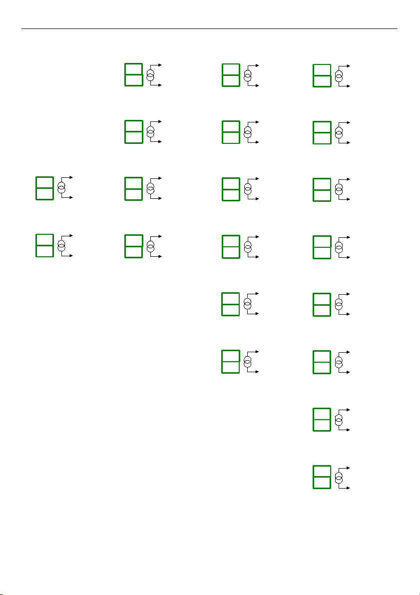
User Manual For - CONTROLLER/DATA RECORDER MultiCon CMC-99/141
Fig. 4.21. Passive current output modules
29
IO6
6 current output
OUT 6
PASSIVE
OUT 5
PASSIVE
OUT4
PASSIVE
OUT 3
PASSIVE
n05
n06
n03
n04
n01
n02
n07
n08
n09
n10
n11
n12
OUT 2
PASSIVE
OUT 1
PASSIVE
IO4
4 current output
n05
n06
n03
n04
n01
n02
n07
n08
OUT 4
PASSIVE
OUT 3
PASSIVE
OUT 2
PASSIVE
OUT 1
PASSIVE
IO2
2 current output
OUT 2
PASSIVE
OUT 1
PASSIVE
n05
n06
n07
n08
IO8
8 current output
OUT 8
PASSIVE
OUT 7
PASSIVE
OUT6
PASSIVE
OUT 5
PASSIVE
n05
n06
n03
n04
n01
n02
n07
n08
n09
n10
n11
n12
n13
n14
n15
n16
OUT 4
PASSIVE
OUT 3
PASSIVE
OUT 2
PASSIVE
OUT 1
PASSIVE
Page 30
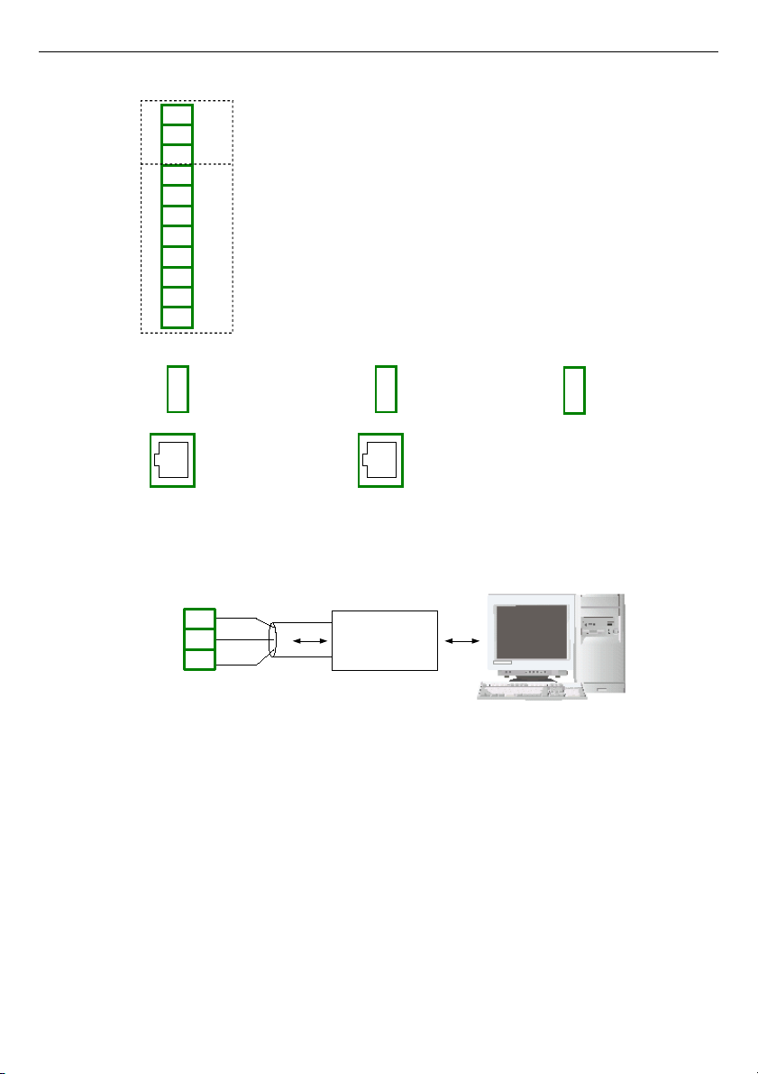
User Manual For - CONTROLLER/DATA RECORDER MultiCon CMC-99/141
Fig. 4.22. Communication Modules
Fig. 4.23. Connection of RS-485 transmission signals
The
MultiCon CMC-99/141
device supports the following converters:
– USB / RS-485 converter
SRS-USB/4-Z45
– RS-232 / RS-485 converter
SRS-2/4-Z45
30
RS232/RS485
or USB/RS485
interface
8
6
7
RS-485
GND
A+
B-
RJ-45
ETH
USB
host
19
16
17
18
14
15
RS-485 (2)
GND
RxD
A+
B-
isolated
13
10
11
12
9
A+
B-
GND
TxD
CTS
RTS
RS-232 + RS-485 (3)
isolated
GND
ACM
RJ-45
ETH
USB
host
ETU
USB
host
USB
Page 31
User Manual For - CONTROLLER/DATA RECORDER MultiCon CMC-99/141
4.4. MAINTENANCE
The unit does not have any internal replaceable or adjustable components available to
the user. Pay attention to the ambient temperature in the room where the unit is operating.
Excessively high temperatures cause faster ageing of the internal components and shorten
the fault-free time of the unit's operation.
In cases where the unit gets dirty do not clean with solvents. For cleaning use warm water
with small amount of detergent or in the case of more significant contamination ethyl or
isopropyl alcohol.
Using any other agents can cause permanent damage to the housing.
Product marked with this symbol should not be placed in municipal waste. Please
check local regulations for disposal of electronic products.
5. INTRODUCTION TO MultiCon CMC-99/141
5.1. UNDERST ANDING CONTROLLER/DATA RECORDER MultiCon CMC-99/141
The
MultiCon CMC-99/141
device was developed as a universal multichannel
controller. To maintain this concept its firmware was written with multi level structure. The
device runs under the control of a LINUX operating system keeping all subsystems ready to
use and allowing independent and simultaneous operation of many processes
(communication, data acquisition, post-processing, visualisation etc.). Such an approach
gives great advantages to high level applications, making it flexible and dynamically
configurable. Similarly data structures and streams were implemented in quite a different way
than in most similar devices. The main difference is the concept of using
Logical Channels
as a bridge: physical inputs and outputs - visualisation and controlling processes. Designers
of
MultiCon CMC-99/141
decided to use such solution to increase functionality of the device
and make software near fully independent on the hardware.
31
!
Page 32
User Manual For - CONTROLLER/DATA RECORDER MultiCon CMC-99/141
5.1.1. Logical channels
A
Logical Channel
is a data stream existing in the memory of the device, having it's
own name and can be displayed in almost any way.
Logical Channels
can be used as:
– measurement inputs,
– data source of control loop,
– control source of the physical outputs,
– input data to other
Logical Channels
,
– data source for visualisation and logging.
Depending on type, the device can be equipped with different number of
Logical
channels
and other functions. Their amount is shown in table bellow:
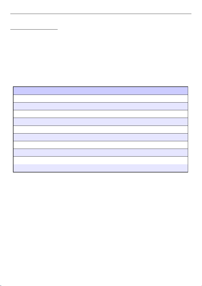
type 96 x 96 144 x 144
LC
(logical channels)
60 90 (60 with logging option)
Di
(digital inputs)
48 72
Ai
(analog inputs)
48 72
Rel/SSR
(relays/SSR)
16/48 36/72
Ao
(analog outputs)
12 24
MP
(Modbus ports)
4 4
F
(math functions)
34 34
G
(groups)
10 15
P/t
(Profile/timers)
8 8
C
(controllers)
8 8
Tab.5.1 Maximum amount of functions, included in device
32
Page 33
User Manual For - CONTROLLER/DATA RECORDER MultiCon CMC-99/141
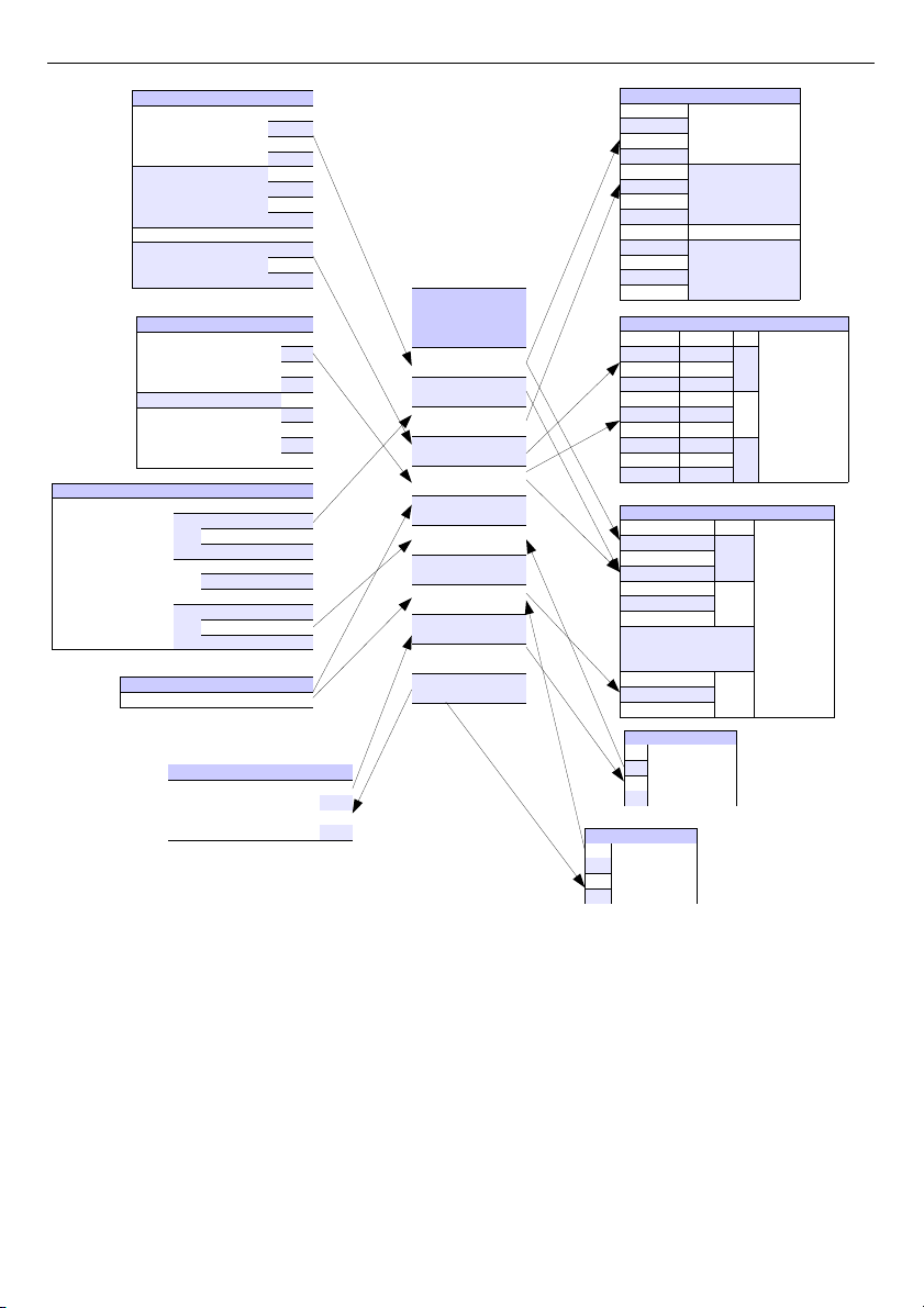
Fig. 5.1. The overall connections structure of the Logical channel with the device I /O
Fig. 5.1
shows general structure of of connections between logical channels, and device
inputs/outputs. Each of
Logical Channels
can be configured to represent:
– measurement data from built-in physical input channels,
– output data and states of physical output channels,
– output data and states of external modules connected to
MultiCon CMC-99/141
via
RS-485 interface,
– states and data coming from outputs of controlling processes,
– generated profile/timer
– states of virtual input channels, and timers,
– mathematical combination of other
Logical Channels
.
33
Modbus input
Hardware input
Digital input
Analog input
Digital input 24V X2
Virtual demo input
(sinus, tringle,
rectangular)
Output monitor
Relays
Sound signal X1
Virtual relay
Modbus
port address input
1 1
1
... ...
255 100
1 1
...
.. ...
255 100
1 1
MP
... ...
255 100
Set point value
Value -1E6 ÷ 1E6
Math function
Function
1
2
...
Di
1
2
...
Ai
X3
X4
X5
Rel
V16
Built-in output
1
2
Relay/SSR
...
Rel/SSR
1
2
Analog output
...
Ao
X1 Sound signal
V1
V2
Virtual relay
...
Logical
1
2
...
channel
1
2
V1
V2
...
3
4
5
...
...
...
...
...
...
LC
1
2
...
F
V16
output address port
1 1
100 255
1 1
100 255
1 1
100 255
Slot Group
Profile/timer
1
2
Profile/timer
...
P/t
Controller
1
2
Controller
...
C
External output
Groups
1
6
1
6
...
1
6
1... ...
2... ...
MP... ...
1...
Visualization
2...
G...
Remote
Modbus
output
& logging
(optional)
Page 34
User Manual For - CONTROLLER/DATA RECORDER MultiCon CMC-99/141
More information about Logical channels and samples of configuration Logical channels are
presented in
Chapter 7.8. LOGICAL CHANNELS
.
To make visualization clearer
Logical Channels
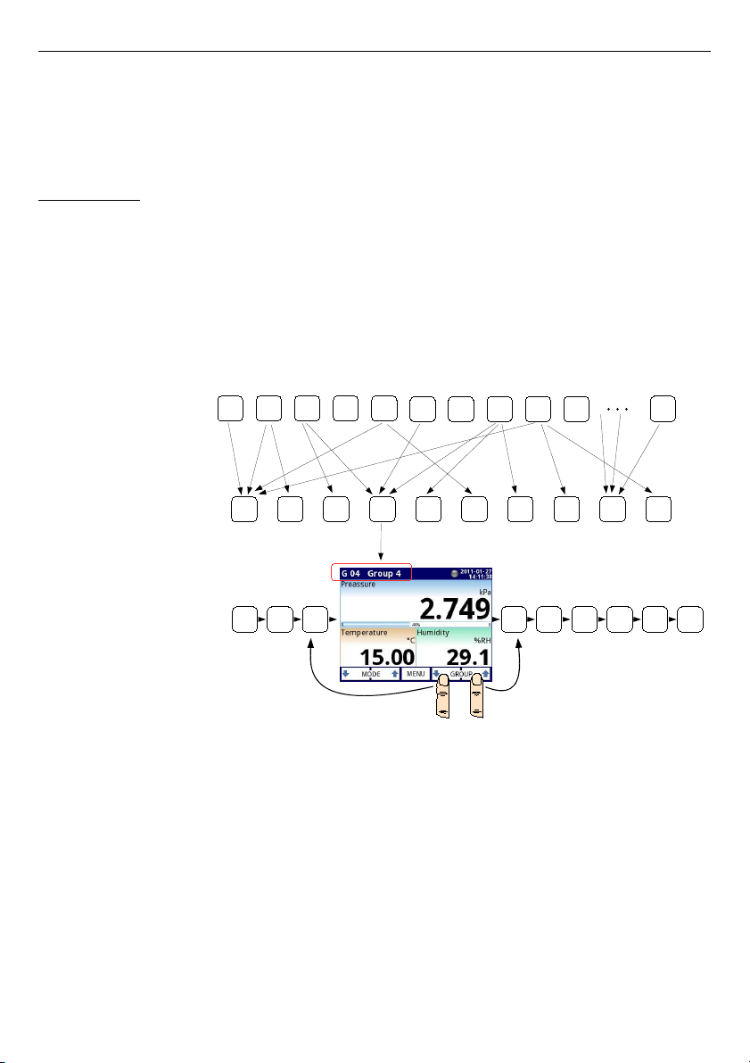
can be gather into
Groups
.
5.1.2. Groups
A
Group
is a set of 1-6
Logical Channels
. The
MultiCon CMC-99/141
can show on the
same screen only channels belonging to the same
Group,
additionally each
Group
has its
own individual name making operation with the device very clear. Every
Logical Channel
can
belong to one or more groups simultaneously, and also not to belong to any group (then it will
not be shown, but it can still be used for other processes). It is common that channels
belonging to the same
Group
are related to one another in some way (for example
representing parameters of single object or representing similar parameters of few separate
objects) but it is also possible to create a
Group
consisting of completely unrelated channels.
Overview of the concept is presented in
Fig. 5.2
.
Fig. 5.2. An overview of the concept of Group in the device
Using
Groups
,
Logical Channels
and mathematical combinations of them gives incredible
flexibility to the software, allowing for ease in designing advanced control methods and
visualisation with a low cost
MultiCon CMC-99/141
.
More information about
Groups
and samples of Group configurations are presented in
Chapter 7.14. GROUPS
.
34
Groups
Logical channels
Visualization and logging
1 2 3 4 5 6 7 8 9 10
60
1 2 3 5
6 7 8 9
10
1 2 3 4 5
6 7 8 9 10
Page 35

User Manual For - CONTROLLER/DATA RECORDER MultiCon CMC-99/141
5.2. HARDWARE CONFIGURATIONS
The functionality of
MultiCon CMC-99/141
can fit to the user's needs. The
base
of the
MultiCon CMC-99/141
contains: the main processor, display with touch-screen, Switch Mode
Power Supply (in one of two versions:
19V...24...50V DC 16V...24...35V AC
and 85V..230..260V
AC) and basic communication interfaces: USB and RS485, see
Fig. 4.8
- most far left
connectors. All other modules are optional and can be installed inside the device according to
customer's needs. Next to the basic connectors is the slot for an advanced communication
module. In the simplest version this module can be equipped only with rear USB Host
connector (this is standard for the IP-65 version of the
MultiCon CMC-99/141
). The full
version of this module contains also 2 additional serial ports (RS485 and RS485/RS232) and
a 10Mb Ethernet RJ-45 connector (see
Fig. 4.22
).
Three slots designed for built-in hardware inputs and outputs are installed on the right
side of the case (see
Fig. 4.8
, terminals marked: slot A, slot B and slot C). The number and
size of these terminals varies depending on module type. Brief descriptions of available
modules are shown in
Fig. 4.9÷Fig. 4.22
. Measurement and actuator modules are constantly
being developed, so the current list of available modules varies (visit manufacturers website
to check current list of
MultiCon CMC-99/141
modules).
Basic measurement modules are:
– 4/8/16/24x Voltage/Current input module,
– 16/24x NTC/Voltage/Current/Digital input module,
– 6x Isolated current input module,
– 2/4x flowmeter + 2/4x current input,
– 2/4x pulse input + 2/4x current input,
– 4/6x RTD input module,
– 4/8/12x TC input module.
– 8/16/24x Digital input
– 3/5x universal input
– 2/4x universal counter input
– 2/4x hourmeter input
Output modules are:
– 8/16/24x SSR driver module,
– 8/12x Relay 1A/250V module,
– 4/6x Relay 5A/250V module,
– 2/4/6/8x IO passive current output.
Communication module:
– ACM,
– ETU,
– USB,
35
Page 36
User Manual For - CONTROLLER/DATA RECORDER MultiCon CMC-99/141
6. WORKING WI TH THE MultiCon CMC-99/141
6.1. MultiCon CMC-99/141 POWER UP
After powering up a starting Logo is showed on the
MultiCon CMC-99/141
display.
While the operating system is being loaded a progress bar is visible in the middle of the
screen. During this process the view of screen may stay dimmed for 3-5 seconds. Please wait
until the end of this operation before starting to operate the device. Additionally, in the last
phase of loading in the lower left corner displays the software version. After that the main
application is started. The view of the main program depends of the
General settings
(see
the
Chapter 7.7. GENERAL SETTINGS
) and
Group
settings (see
Chapter 7.14. GROUPS
).
An example view of the main program shown in
Fig. 6.2
.
6.2. THE USE OF THE TOUCH-SCREEN
Do not use pointers with sharp edges (like tips of pencils and pens, knifes, scissors,
needles, wires, nails, screws, bolts etc.) while working with touch-screen. It is strongly
recommended to use a special stylus made of plastic or another soft material with round ends
(for example the pionter delivered with the device) or a finger. The display of the
MultiCon
CMC-99/141
should also be protected against aggressive substances and extremely high and
low temperature(see technical data in
Chapter 3. TECHNICAL DATA
).
To clean the LCD screen you should use a special detergent designed for LCDs
and a soft cloth.
6.3. DISPLAY
The
MultiCon CMC-99/141
displays all data and dialogue on a 3,5” or 5,7” 320x240
pixel, color TFT screen with embedded touch screen panel. New devices have the display
protected with a thin transparent plastic cover. This protective layer should be removed before
use to ensure perfect visibility of pictures and sensitivity of the touch-screen.
While normal operation the
MultiCon CMC-99/141
displays data in a form selected by
user, at any time it is possible to switch presentation mode and group or show configuration
menu. All details of the user interface are designed to make use of device easy and intuitive.
To change display mode, group or to enter the menu, touch the screen of the
MultiCon CMC-
99/141
and press appropriate button in the
Navigation bar
.
Further information about menu and presentation modes are described in further
chapters.
36
i
!
Page 37
User Manual For - CONTROLLER/DATA RECORDER MultiCon CMC-99/141
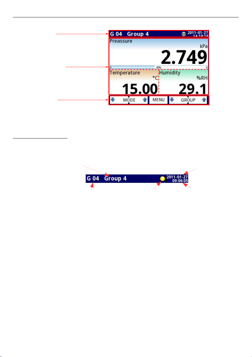
Chapter
6.3.1
Chapter 6.3.3
Chapter 6.3.2
Fig. 6.1. Typical view of a MultiCon CMC-99/141 main page, after touching display
6.3.1. Information bar
The
Information bar
informs the user about current, display group, logging, actual date
and time.
Fig. 6.2. View of information bar
Information bar displays (
Fig. 6.2
):
–
name of the Group
visible on the screen, in place of standard name (e.g.
Group 4
).
It is possible to enter a more descriptive name for clarity (for more information see
Chapter 7.14. GROUPS
),
–
group number
- number of the currently displayed Group, to change the displayed
Group
press button
[↓GROUP]
or
[GROUP↑]
in the
Navigation bar
(see
Chapter
6.3.2. Navigation bar
),
–
time
and
date
- actual time and date display on the right upper corner on the screen
can be set in
General settings
(see
Chapter 7.7. GENERAL SETTINGS
),
–
logging data indicator
- located in the
Information bar
the
logging data indicator
changes color depending of state logging:
•
gray color
- data logging option is not activated (to activate the data logging
option you need to enter the licence key provided by the manufacturer - see
Chapter 7.4. DEVICE INFORMATION, LICENCE, FIRMWARE UPDATE,
REMOTE DISPLAY, EXPORT MANUAL AND RENEW CONFIGURATION
), or
when the logging option is activated but is disabled.
•
green color
- after activation the data logging option indicator changes to green
when the data logging is enabled (for more information about setting data
logging see
Chapter 7.14.2. Groups - Logging options
),
37
Information bar
Data panels
Navigation bar
time
group number
name of the group which is visible on the display
logging data indicator
date
Page 38
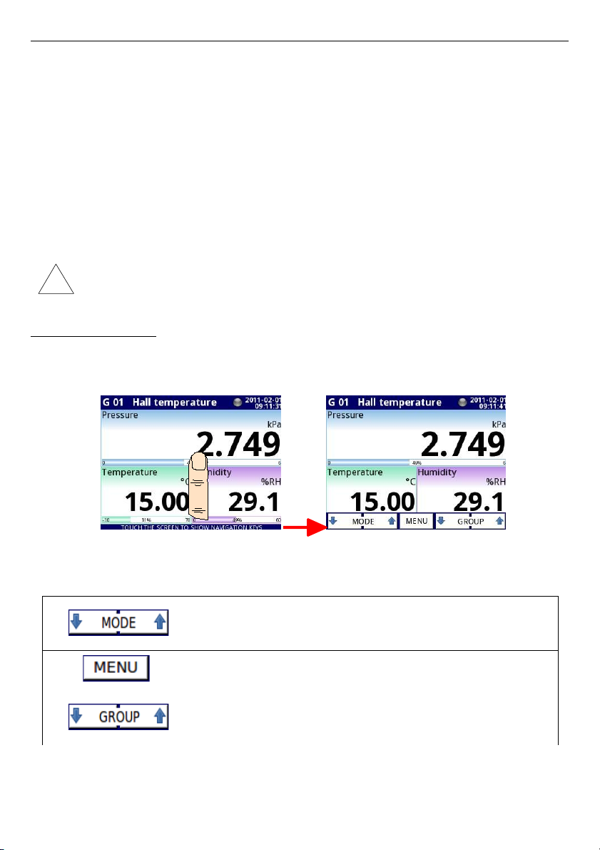
User Manual For - CONTROLLER/DATA RECORDER MultiCon CMC-99/141
•
yellow color
– It is possible to log data in the device but there is less than
20%
of total free memory remaining (to clear the memory you need to move onto a
removable flash drive any important data logging files and possibly the Modbus
templates, after which remove them from the device - more information see
Chapter 7.3. FILES MANAGEMENT
). Also at the moment when free memory
drops bellow 20% a warning will be displayed on the screen.
•
red color
- warning about the lack of space on memory card, meaning data
logging would not be possible until space is freed in the memory (how to remove
data and exchange data with a flash drive is shown in
Chapter 7.3. FILES
MANAGEMENT
)
•
alternately blinking green with a blue color
- when the indicator flashes blue
the logged data is moved to memory (Note! at this time you must not turn off the
device because it may cause a loss of recently logging data).
In order to turn off the device especially when the data logging is ON it is
recommended to use the safe-off device by pressing the button
Safe-shutdown
in
the main menu (see
Fig. 7.14
).
6.3.2. Navigation bar
The touching the screen at any place causes the
Navigation bar
to display
(see
Fig. 6.3
) which allows the user to switch between visualisation modes, groups and to
enter the menu.
Fig. 6.3. Main window of device – displaying the Navigation bar
This bar contains three kinds of buttons shown in
Tab. 6.1
.
switching between visualisation modes of current group (for
possible modes see
Chapter 6.3.3. Data panels
and
Chapter
7.14. GROUPS
)
entering the main menu (see details in
Chapter
7. CONFIGURATION OF THE MultiCon CMC-99/141
)
switching between presented groups of logical channels
(activation and settings for
Group
view see
Chapter 7.14.
GROUPS
)
Tab. 6.1 Buttons of the navigation bar
38
!
Page 39
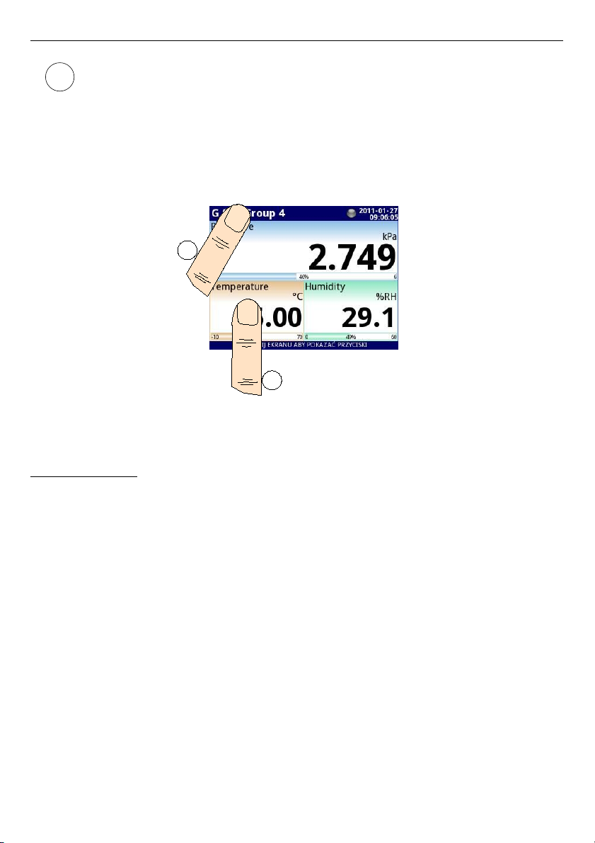
User Manual For - CONTROLLER/DATA RECORDER MultiCon CMC-99/141
To enter directly into the configuration menu of particular
Logical channel
, press
and hold screen over the channel data panel for 3-4 seconds (see option
(1)
in the
Fig. 6.4
entering configuration of the
logical channel
named
'Temperature'
).
Similarly to go directly to configuration of displayed
Group
, touch and hold
the group number
or
group name
in the upper
Information bar
for a few
seconds (see option
(2)
in the
Fig. 6.4
entering configuration of the
Group
named
'Group 4'
). In both cases if a password is set (see
Chapter 7.17. ACCESS
OPTIONS
) then the user has to enter the password before entering the
configuration.
Fig. 6.4. Methods for direct entry to Logical channel configuration (1) and Group
configuration (2)
6.3.3. Data panels
The great deal of the screen is being used for channel visualisation. Data can be
presented in one of the following modes:
– as numerical values,
– as charts,
– as bars,
– as needle dials.
All channels of the current group are simultaneously presented in the same mode. In the
current version of software there is no possibility to mix different modes in one view. Figures
6.6
÷
6.11
show examples of different views. The switching between visualisation modes can
be done by pressing the buttons
[MODE↑]
or
[MODE↓]
in the
Navigation bar
(see
Chapter
6.3.2. Navigation bar
). Switching between groups can be done by pressing the buttons
[GROUP↑]
or
[GROUP↓]
.
39
1
2
i
Page 40
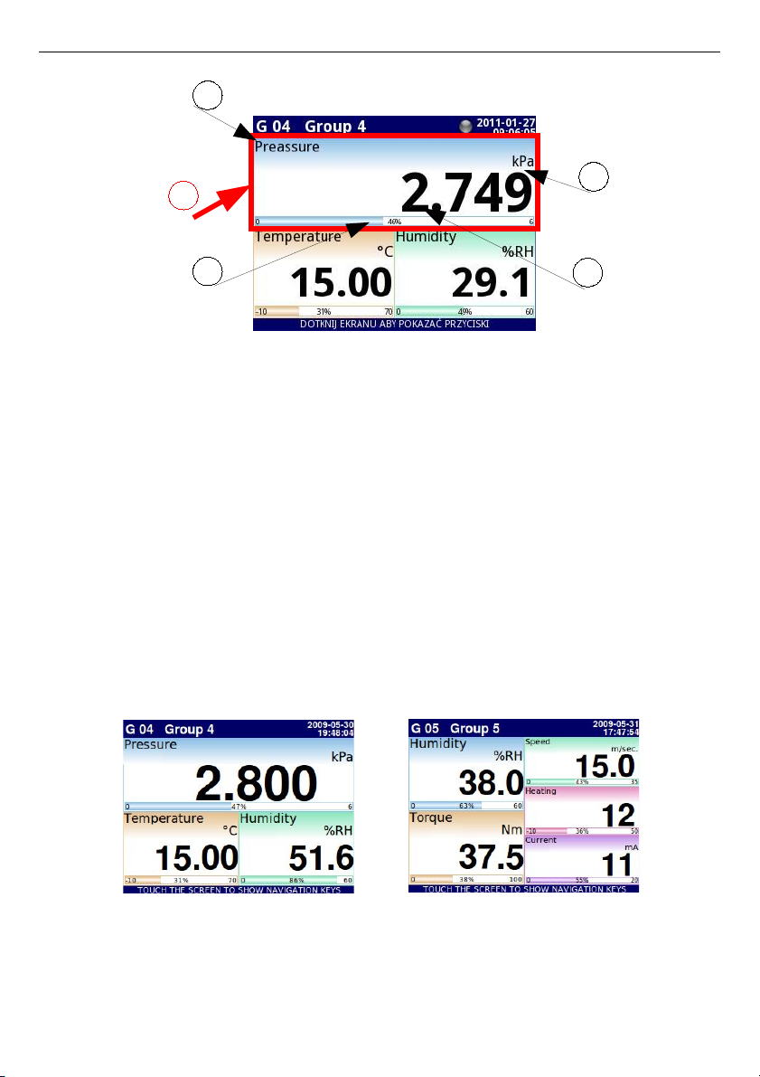
User Manual For - CONTROLLER/DATA RECORDER MultiCon CMC-99/141
Fig. 6.5. View of the Data panel
In all data panels (a sample of a data panel is shown inside the frame marked
(1)
in
Fig. 6.5
)
the following information is available:
– value of the logical channel (denoted by
(2)
in
Fig. 6.5
),
– data unit (denoted by
(3)
),
– channel's name (denoted by
(4)
),
– on some modes there is also a visible percentage indicator of the value in relation to
it's full scale (denoted by
(5)
),
Every
Group
of
Logical Channels
can be presented in one of 6 modes:
– as numerical values
Fig. 6.6
– as horizontal bars
Fig. 6.7
– as vertical bars
Fig. 6.7
– as horizontal charts
Fig. 6.8
– as vertical charts
Fig. 6.8
– as phasor charts
Fig. 6.9
– as needle dials
Fig. 6.10
Fig. 6.6. Examples of Numerical Values presentation mode
40
5
4
3
2
1
Page 41
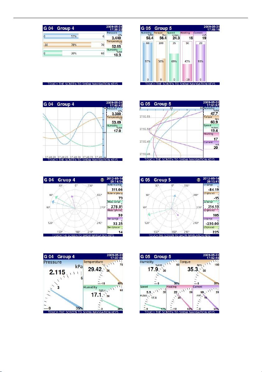
User Manual For - CONTROLLER/DATA RECORDER MultiCon CMC-99/141
Fig. 6.7. Examples of Horizontal (for 3 channels) and Vertical Bars (for 5 channels)
Fig. 6.8. Examples of Horizontal (for 3 channels) and Vertical Charts (for 5 channels)
Fig. 6.9 Examples of Phasor Charts presentation mode
Fig. 6.10. Examples of Needle Dials for 3 channels and for 5 channels
41
Page 42
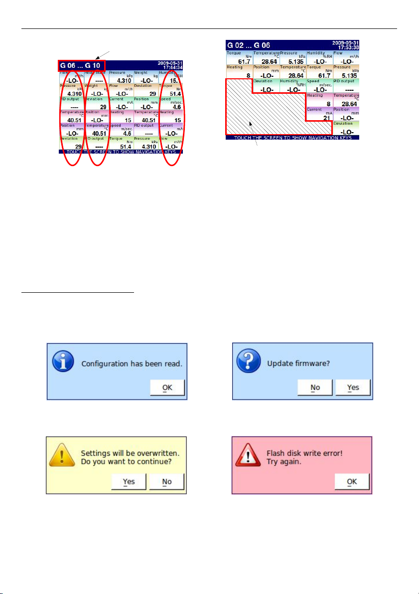
User Manual For - CONTROLLER/DATA RECORDER MultiCon CMC-99/141
Fig. 6.11. Examples of simultaneous presentation of Many Groups
There is also the possibility to show many groups on a single screen (
Fig. 6.11
). In this
mode channels belonging to the same group are displayed under one another, and groups
are placed side by side. As much as 5 groups can be displayed simultaneously on a single
screen (for example, groups starting from group 8 will display on the screen, starting from the
left side of the page, groups: 8, 9, 10, 1, 2),
See
Chapter 7.14. GROUPS
for more information about
Groups
.
6.3.4. Important messages
The user will sometimes be asked, informed and alerted about a variety of events by
messages displayed on the screen. Figures show below (
Fig. 6.12÷Fig. 6.15
) present
examples of message types.
Fig. 6.12. Information message Fig. 6.13. Question message
Fig. 6.14. Warning message Fig. 6.15. Alert message
42
Group
6
7
10
Index of displayed groups
. . .
Inactive logical channels in the groups
Page 43
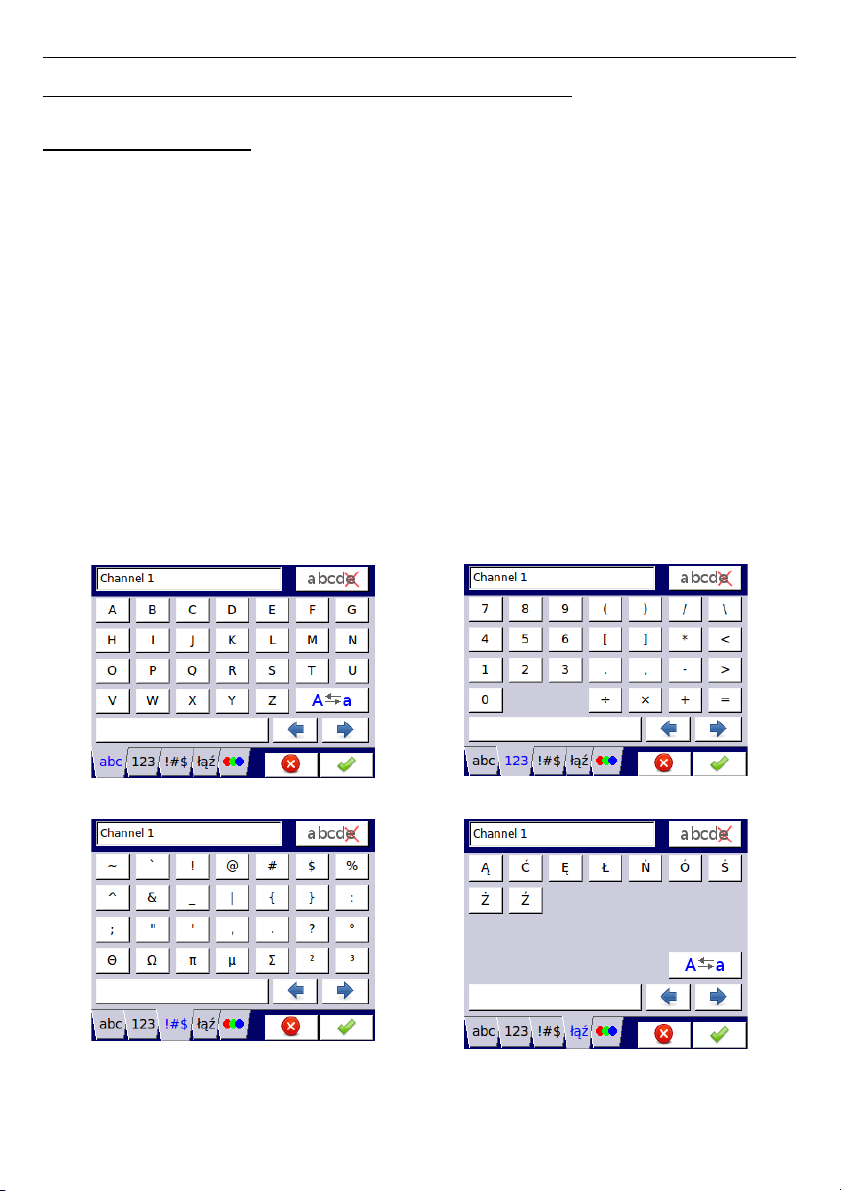
User Manual For - CONTROLLER/DATA RECORDER MultiCon CMC-99/141
7. CONFIGURATION OF THE MultiCon CMC-99/141
7.1. EDIT DIALOGUES
Configuration process are based on edit dialogues. Some of the dialogues are common
to different menus, such dialogues are:
– text editor, which is divided into tabs:
• letters, see
Fig. 7.1
,
• numbers and arithmetic signs, see
Fig. 7.2
,
• the special symbols, see
Fig. 7.3
,
• diacritical letters,
Fig. 7.4
,
• font and background colors, see
Fig. 7.5
,
– values editor, which is divided into tabs:
• decimal form, see
Fig. 7.6
,
• hexadecimal form, see
Fig. 7.7
,
• binary form, see
Fig. 7.8
,
– switch editor, which is divided:
• single choice type options, see
Fig. 7.9
,
• multiple choice type options, see
Fig. 7.10
,
– file editor, which is divided:
• single file selection, see
Fig. 7.11
,
• multiple files selection, see
Fig. 7.12
,
Fig. 7.1. Text editor – letters Fig. 7.2. Text editor – numbers
Fig. 7.3. Text editor – special symbols Fig. 7.4. Text editor example – diacritical
letters
43
Page 44
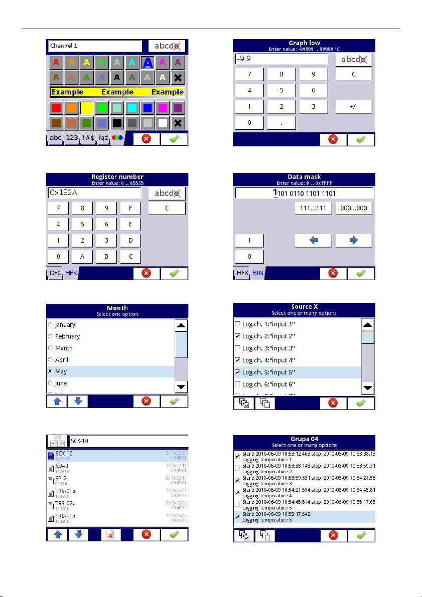
User Manual For - CONTROLLER/DATA RECORDER MultiCon CMC-99/141
Fig. 7.5. Text editor – font and background
color selection
Fig. 7.6. Value editor – decimal form
Fig. 7.7. Value editor – hexadecimal form Fig. 7.8. Value editor – binary form
Fig. 7.9. Single choice type editor
Fig. 7.10. Multiple choice type editor
Fig. 7.11. File editor - single file selection Fig. 7.12. File editor - multiple file selection
44
Page 45
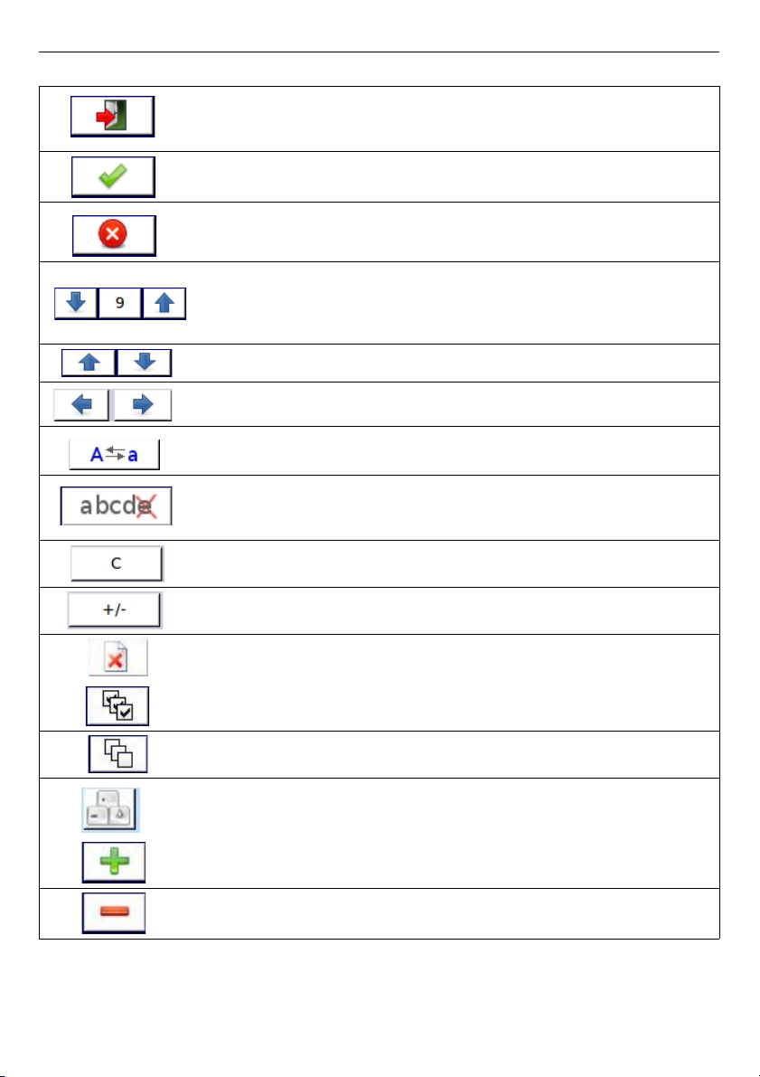
User Manual For - CONTROLLER/DATA RECORDER MultiCon CMC-99/141
Functions of common buttons
“
Exit
” - exits from current menu or sub-menu
”OK” - accept choice or changes of edit dialogue (and exit from this
dialogue)
“
Cancel
” - reject entered choice or changes of edit dialogue (and exit
from this dialogue)
Selection of element for editing. Arrow buttons allow the user to select
successive elements (groups, logical channels, controllers or outputs).
The middle button allows a direct selection of particular element from
the list.
Navigation keys in choice type dialogues.
Move arrows. Allow to move cursor along the edited text.
“
Caps lock
” - switches between lower and upper case letters.
“
Backspace
”. When editing values, pressing this button deletes last
visible number. When editing text, the last edited symbol shown
directly before cursor is deleted.
“
Clear
” - clears the whole number when editing values.
“
Sign
” - changes the sign of the edited value.
This button deletes the selected file.
“
All
” - selects all the available options.
“
None
” - deselects all the available options.
Press this button to enter Text editor window.
Add a new object
Delete a selected object
Tab.7.1 Button functions common for different views
45
Page 46
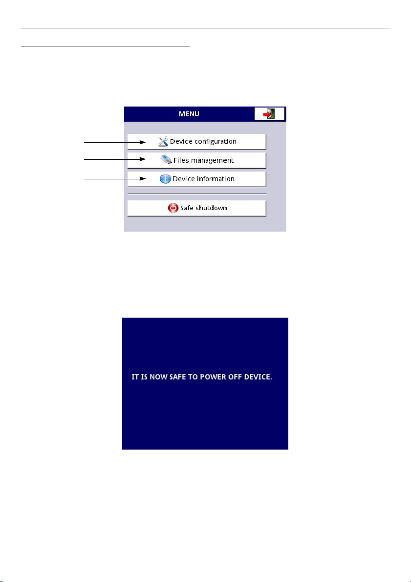
User Manual For - CONTROLLER/DATA RECORDER MultiCon CMC-99/141
7.2. MAI N MENU SELECTION PANEL
Pressing the
[MENU]
button on the
Navigation bar
(see
Chapter 6.3.2. Navigation
bar
) enters the main selection panel (see
Fig. 7.13
). This panel allows users to select
between entering the
Device Configuration
menu,
Files management
menu and
Device
Information
window.
Further information about the different menus are described in further chapters.
Chapter 7.5
Chapter 7.3
Chapter 7.4
Fig. 7.13. Main menu window
The
Safe shutdown
button allow for a safe power down of the device. After pressing the
button and accepting the
warning message
the screen will look like in the
Fig. 7.14
. Now,
the user can power off the device. The manufacturer recommends turning off the device this
way. This method is especially recommended when data logging is enabled. Not complying
with these instructions could cause loss of recently logged data samples.
Fig. 7.14. The view of the screen after pressing the Safe shutdown button
46
Page 47
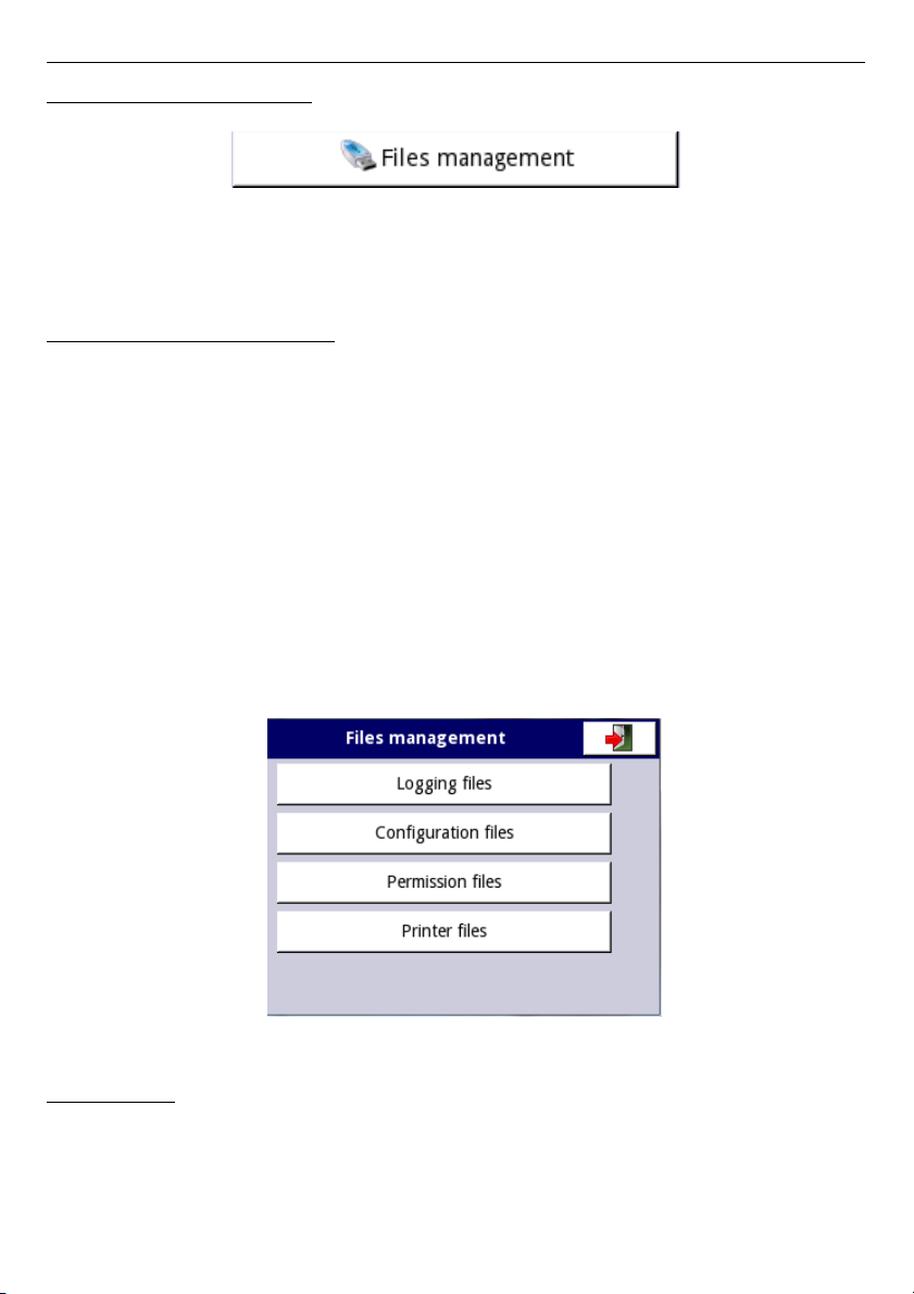
User Manual For - CONTROLLER/DATA RECORDER MultiCon CMC-99/141
7.3. FILES MANAGEMENT
Fig. 7.15. This button allows to entry to the files management menu
After pressing
MENU -> Files management
(see
Fig. 7.15
) opens the files
management menu which is used to exchange data with a flash drive.
Requirements for a flash drive:
– Maximum current consumption is 100mA. Some flash drives with large capacities are
not supported by the device (in this case can use an external USB hub with power
supply). The manufacturer recommends the use of flash drives of 2GB in size.
– The flash disk must be formatted for Windows as FAT (NOTE!! not FAT32).
– update files, configurations files, and Modbus templates must be located in the main
folder (the root of the drive).
A view of the
File management
menu is shown in
Fig. 7.16
. There are four buttons
called
Logging files, Configuration files, Permission files
and
Printer files
.
The
Logging files
button is always visible and it contains all possible parameters but
their functionality is blocked until the licence key for data logging is entered (more information
about the licence key is located in
Chapter 7.4.
). The
Configuration files
button is visible
and active always. The
Permission files
button is available when
Access mode
parameter
in
Access options
menu is set as
MultiLevel
(see
Chapter 7.17.
).
Printer files
button is
always visible but this functionality is active only when
MultiPrint MLP-149
printer is
connected to the device.
Fig. 7.16. Files management menu
Logging files:
The
Logging files
button (see
Fig. 7.16
) opens the logging files management menu
(see
Fig. 7.17
). To export and/or delete logged files follow these steps:
– select a file/s of logged data from a group,
– select the more files in the other groups (if needed),
– export selected files to flash drive and / or delete selected logged data files,
47
Page 48
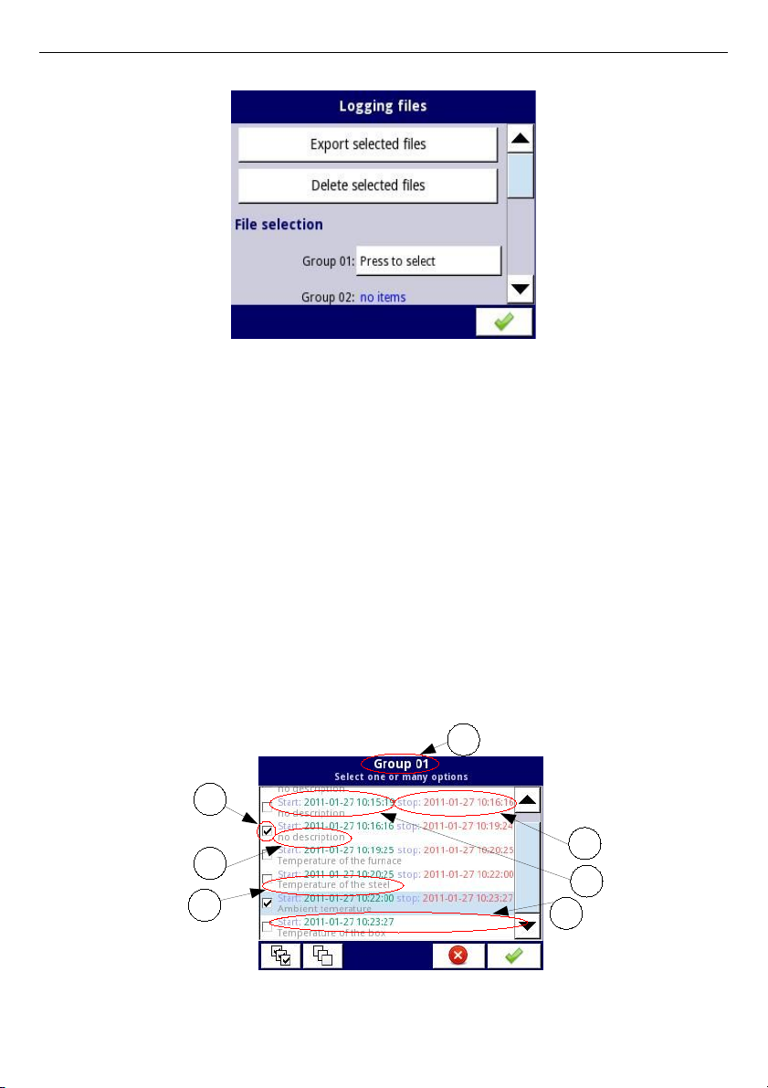
User Manual For - CONTROLLER/DATA RECORDER MultiCon CMC-99/141
Fig. 7.17. Logging files menu
The
Logging files
menu is presented in
Fig. 7.17
. The menu consists of buttons:
–
Export files
- after pressing this button the selected logged files will be exported to a
flash drive,
–
Delete files
- after pressing this button the selected logged files will be removed
from the device,
–
Press to select
next to the
Damaged files
label- (this button is visible if at least one
damaged file exists) when the user presses this button the window with a list of
damaged files is dispayed (the damaged logging files are those that contain errors
caused by inappropriate shutdown the device during data logging). There is no
guarantee that this logged data will be readable,
–
Press to select
next to
Group number
label - if the user has enabled the logging of
particular group of logical channels (see
Chapter 7.14.2. Groups - Logging
options
) in the
Logging files
menu next to the label of the group number appears
the button
'Press to select'
. Depending on how many groups (the device can define
10 groups) logging is enabled (past or present) as many
'Press to select'
buttons
will be active.
Fig. 7.18. A sample view of selected logged files from Group 1
48
2
1
3
4
5
6
7
Page 49
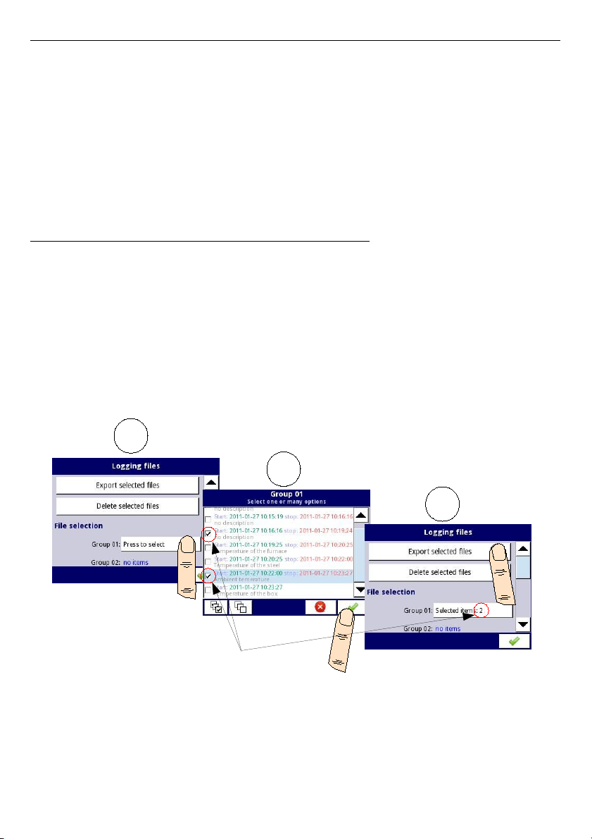
User Manual For - CONTROLLER/DATA RECORDER MultiCon CMC-99/141
In
Fig. 7.18
presents a sample view of selected logged files from Group 1. The numbers refer
to:
–
(1)
- group number,
–
(2)
- the selected logged file,
–
(3)
- no description for the logged file,
–
(4)
- description defined by the user (a description of the logged file is defined in the
Groups menu - see
Chapter 7.14.2. Groups - Logging options
–
(5)
- date and time of the end of the logged data file,
–
(6)
- date and time of the start of the logged data file,
–
(7)
- date and time of the start of the logged data file whose logging has not yet
ended.
An example of exporting the logged data to a flash drive
An example of exporting 2 logged files from group 1 is shown in
Fig. 7.19
. First plug the flash
drive into the device (when the device is equipped with one of the communication modules).
– In step
(1)
, press the button
Press to select
next to the
Group 01
label,
– In step
(2),
select 2 files by pressing the selected files and then choose the button to
accept:
• File 1. Name: "no description", Start: 2010-12-01 3:24:58 p.m., stop: 2010-12-01
4:34:11 p.m. "
• File 2. Name: "Ambient temperature" Start: "2010-12-03 9:53:15 a.m.",
stop: "2010-12-03 9:55:00 a.m."
– In step
(3)
, press the
Export selected files
button and wait for a message to end the
operations of exporting data to a flash drive,
Fig. 7.19. Steps of exporting logged files to flash drive
After exporting logged files a folder is created on the flash drive with the same name as the
product identification number, which includes a folder with the selected logged files.
Deleting files from the device is similar export logging files, the difference is that instead of
pressing the
Export selected files
button in
(3)
step (see
Fig. 7.19
), press the
Delete
button.
49
1
2
3
Page 50
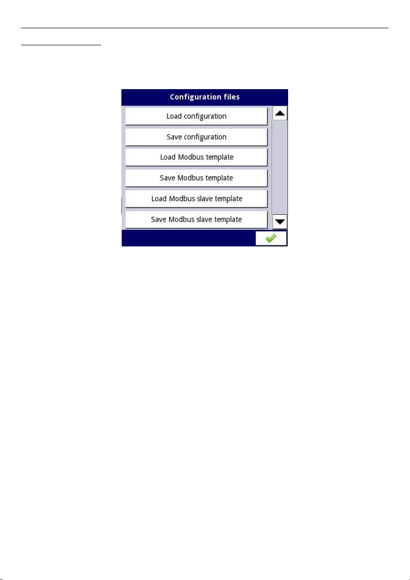
User Manual For - CONTROLLER/DATA RECORDER MultiCon CMC-99/141
Files management:
The second button on the
File management
menu is the
Configuration files
button.
Pressing this button, will open the menu shown in
Fig. 7.20
, which allows the user to
load/save the configuration and Modbus templates.
Fig. 7.20. View window when the configuration changes
Load/save configuration
will load/save the configuration defined by the user, which includes:
– general settings (see
Chapter 7.7. GENERAL SETTINGS
),
– logical channel settings,
– built-in, external inputs settings,
– built-in, external output settings,
– Modbus protocol settings,
– profile/timer settings,
– control settings,
– network settings,
– group settings,
Load/save Modbus templates
allows the user to load/save the configuration of the Modbus
MASTER protocol, e.g.:
– name,
– configuration of the device channels (the list of inputs and outputs)
– configuration of register blocks (block list) - see
Chapter 7.15.3. Modbus - MASTER
mode
,
Having saved these Modbus templates means the user can at any time quickly establish a
connection between the MultiCon and the SLAVE devices, needing only to choose the
appropriate address of the SLAVE devices (more about templates in
Chapter 7.15.3.
Modbus - MASTER mode,
).
50
Page 51
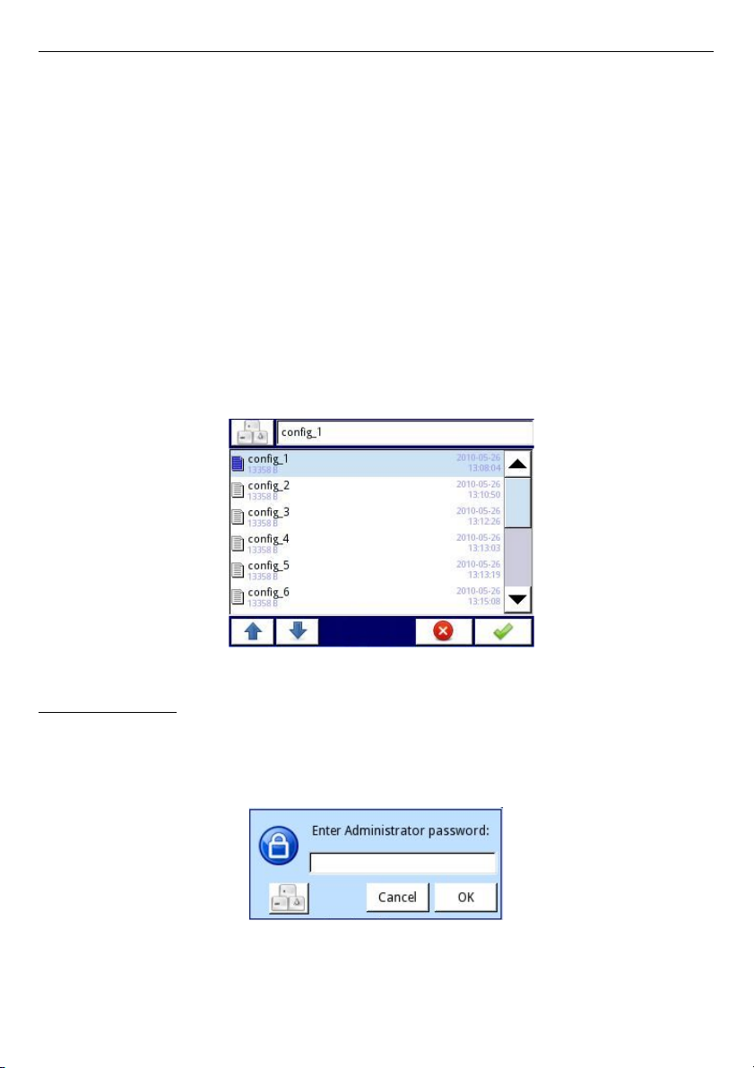
User Manual For - CONTROLLER/DATA RECORDER MultiCon CMC-99/141
Load/save Modbus slave templates
allows the user to load/save the configuration of the
Modbus SLAVE protocol with a defined block of registers, e.g.: register type (Holding/Input),
write mode of register, data format (16 bits or 32 bits). For configuration of Modbus SLAVE
see
Chapter 7.15.2. Modbus - SLAVE mode
,
The process of exchanging configuration files or Modbus templates between the MultiCon and
flash drive starts when you plug the flash drive to the unit. Then enter
MENU -> File
management -> Configuration Files
. If you want to
Load configuration/template
the
window panel will show a view of the contents of the flash drive with the available files:
– for
configuration file
with extension
.cfg
,
– for
Modbus template file
with extension
.mcfg
,
– for
Modbus slave template file
with extension
.scfg
,
Please note that the file name is defined by the user. If the user wants to
Save
configuration/Modbus template
, press the
Save configuration, Save Modbus template
or
Save Modbus slave template
button. A window appears with the available files that can be
overwritten or a new file can be created by pressing button with keys symbol in the upper left
corner (see
Fig. 7.21
). After confirming the write process the data is stored on the flash drive.
An example of configuration files in
Fig. 7.21
.
Fig. 7.21. Example of logging and configuration files
Permissions files:
Third button in the
Files management
menu is
Permission files
. This menu is related
with
MultiLevel Access
mode (see
Chapter 7.17.
). Access to that menu has only user
logged as Administrator. If no user is logged, the administrator's password must be passed to
open that menu (see
Fig. 7.22
).
Fig. 7.22. Enter password dialogue
51
Page 52
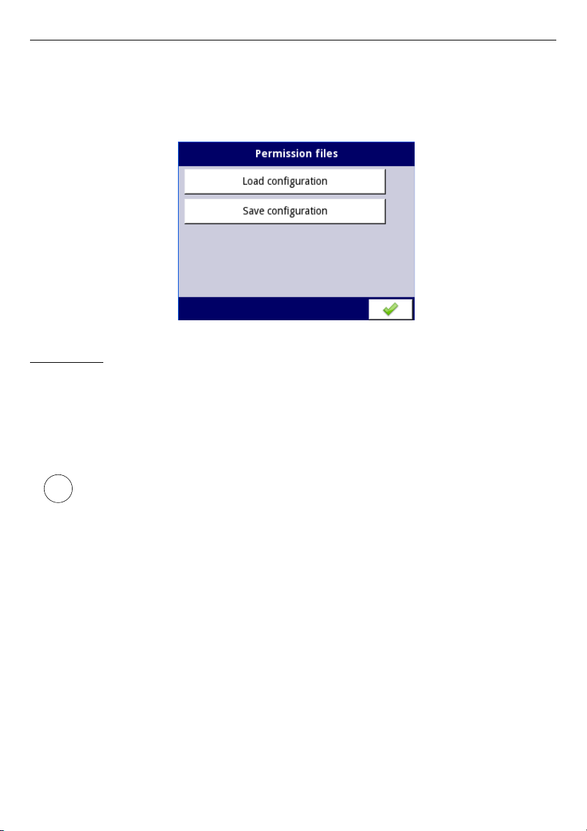
User Manual For - CONTROLLER/DATA RECORDER MultiCon CMC-99/141
In this menu Administrator has access to two buttons:
Load configuration
and
Save configuration
(see
Fig. 7.23
) which allows to store and move saved access settings
using external USB flash drive. That streamlines the process of setting up another devices. It
is the only way to save
Access options
settings (see
Chapter 7.17.
) , main configuration file
doesn't contain those settings.
Fig. 7.23. Enter password dialogue
Printer files:
Fourth button in the
Files management
menu is
Printer files
. It is always visible but
functionality is active only when to the device
MultiPrint MLP-149
printer is connected.
Printer description is shown in
8.16. MULTIPINT MLP-149 – EXTERNAL PRINTER
. In Printer
files menu contains two buttons:
–
Load image
– loads image from flash drive and saves it in device's memory in order
to use it in printing processes as header or footer,
–
Delete image
– removes selected image from the device's memory,
Printouts description is shown in
7.18. PRINTOUTS
.
52
i
Page 53
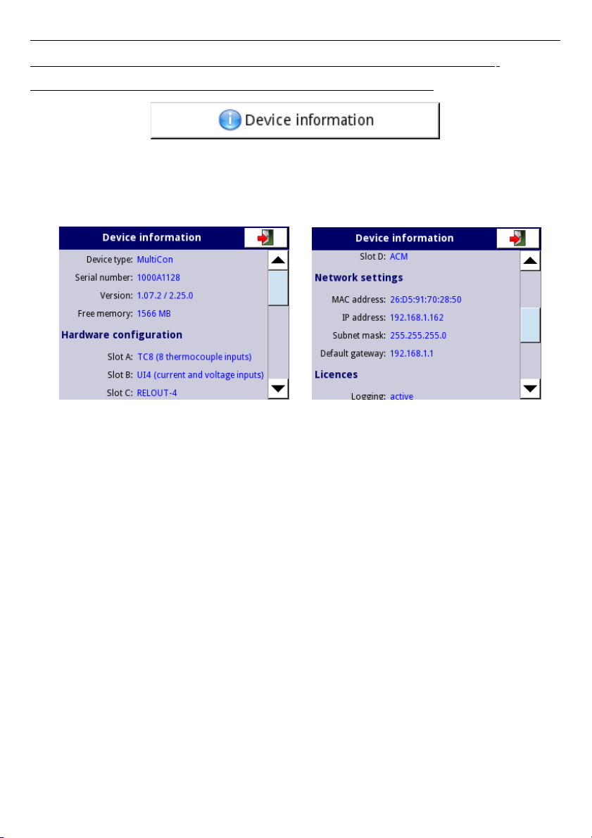
User Manual For - CONTROLLER/DATA RECORDER MultiCon CMC-99/141
7.4. DEVICE INFORMATION, LICENCE, FIRMWARE UPDATE, REMOTE
DISPLAY, EXPORT MANUAL AND RENEW CONFIGURATION
Fig. 7.24. The button which will show information about the device
The
Device information
menu gives basic information about the device and allows the
user to enter a licence key for data logging, perform a firmware update of the device, run
displaying on the remote screen and download a user manual to the flash drive.
Fig. 7.25. Device Information screens
Pressing the
MENU -> Device information
button (see
Fig. 7.24
) will show window (see
example window information
Fig. 7.25
) with basic information about software and hardware
on the device, such as:
– type of device,
– serial number,
– version of the software
– available free memory,
– hardware configuration - a list of installed modules (
number of slot: module type
)
– network settings,
– active licences.
Enter licence key
button (see
Fig. 7.27
) allows the user to enter a licence key purchased
from the manufacturer (or supplier), enabling additional software options which enhance the
functionality of the device. After entering and accepting the licence key the device
automatically starts up with new software options (e.g. if the licence key for data logging is
entered the text under the
Licences
heading appears as:
Logging
: the period of validity –
see
Fig. 7.27
).
Firmware update
button (see
Fig. 7.27
) allows the user to update the device software. To
perform the update:
– download the latest software version available form the multicon24.eu website ,
– unzip file and copy to a flash drive,
– plug in the flash drive (some high capacity Pendrives are not supported, best choice
is pendrive with 2GB capacity) - start the update process by pressing the
Firmware
update
button (see
Fig. 7.27
).
53
Page 54
User Manual For - CONTROLLER/DATA RECORDER MultiCon CMC-99/141
Note on the update:
– do not power off the device or remove the flash drive from the USB port during the
update,
– the update process must go continuously to the end, the user will be informed of the
progress throughout the update cycle;
Attention! The user can not start an unfinished update again because this may
damage the device,
– there can not be more than one update file on a flash drive,
– update files must reside in the main folder (root of the drive),
– the update process may take about 5 minutes, depend on the version of the device.
The requirements for removable flash drives are presented in
Chapter 7.3. FILES
MANAGEMENT
.
The
Remote display
button allows the MultiCon to communicate with the PC to display the
screen of the
MultiCon
on the PC monitor to configure and view the data.
This button is available only for devices with installed ACM or ETU module.
Below please find a step by step description of how to configure the
MultiCon
with a PC.
1.
Download free “
Xming
” software from http://sourceforge.net/projects/
xming/files/Xming/6.9.0.31/Xming-6-9-0-31-setup.exe/download
2.
Install “
Xming
” on your PC using default settings. During installation enable create a
desktop icon for “
Xming
” option and disable “
Launch Xming
” option.
3.
After installation of "
Xming
" use the right mouse button to open the properties
window for desktop icons of the "
Xming
" and replace the “
-multiwindow”
with
“
-ac -kb -notrayicon -screen 0 320x240+900+400”
, then close the window
properties. “
Xming
" in cooperation with the
MulitCon
device allows to change the
following parameters selected below:
Fig. 7.26 Xming parameters description
Screen number in "
Xming"
should be set the same as the value of the
Screen number
parameter in
Network settings
submenu in
MultiCon
device (see below the point 5).
4.
Next close the window properties and run “
Xming
” using desktop icon.
5.
In “
Network settings
” of the device in the group "
Remote Display
" enter the
IP address
of your computer and “
Screen number=0"
, then exit menu and save
configuration changes.
6.
In the “
Device information
” menu press the “
Remote display
” button and confirm
switching to remote display. After a while the device screen will be redirected to your
computer screen.
54
i
xming.exe :0 -ac -kb -notrayicon -screen 0 320x240+900+400
Screen number (0÷9)
Shift the screen by 900 pixels to the right and 400 pixels down,
Page 55

User Manual For - CONTROLLER/DATA RECORDER MultiCon CMC-99/141
To establish connection between the device and PC, port number 6000 must be
unlocked in software and hardware firewall.
The
Export manual
button allows you to download the user manual on to the flash drive.
The
Service options
button (see
Fig. 7.27
) allows the user to:
– Delete current configuration and restore default settings (excepting Access options –
see
Chapter 7.17.
). It is done by passing the password, which is “
RENEW
CONFIGURATION
".
– Calibrate RTC clock in the device. RTC is hardware clock which measures time
when the device is switch off. This calibration increases precision of the device and
should be made in order to compensate work temperature effect.
To do this press
Service options
button and pass the password, which is “
RTC
CALIB
” and then enter current time and date. After at least two weeks password
should be entered again and once again current time and date.
– Calibrate system clock in the device. It is software clock which is clocked by the CPU
and it measures time while the device is switch on. During calibration a delay
between RTC and system clock is calculated and used to correct software clock
measurements. This calibration shuold be made after RTC calibration is done.
To do this press
Service options
button and pass the password, which is “
SYSCLK
CALIB
” and then the device should be powered for at least 48 hours. After this time
pass this password again.
Fig. 7.27. Device information menu
Remote display mode should not be used for normal device work, but only for its
configuration.
55
i
i
Page 56
User Manual For - CONTROLLER/DATA RECORDER MultiCon CMC-99/141
7.5. DEVICE CONFIGURATION
Fig. 7.28. The device configuration menu
The
Device configuration
menu is the main menu of the device that allows the user to
configure all inputs and outputs of the device to measure and control the system.
To prevent accidental or unauthorized change the settings in the
Device configuration
menu
the user can set the access protection (see
Chapter 7.17. ACCESS OPTIONS
). If this option
is set, before entering each submenu, the user will be requested to enter the password.
More information about selected sub-menus is described in further Chapters.
To exit the main menu, press the button located in the upper right corner of the screen.
Due to the fact that the configuration process takes place in real time, all changes must be
confirmed before saving them. In the confirmation window, you can
Save
or
Revert changes
(see
Fig. 7.30
).
There is a possibility to press the button again. In that case warning message will appear
(see
Fig. 7.31
), and the user must choose to save new configuration or go to main screen
with unsaved but active configuration. If second option is chosen, the icon: , will be
displayed on the information bar, the device will also keep new configuration in memory and
user can determine are those changes gave the desired effect (see
Fig. 7.32
). This operation
can be repeated any number of times, as long as new configuration is saved or the old one is
reverted.
In case of power failure, changing to remote or local display, any unsaved
settings will be lost, and the last saved configuration will be restored.
56
i
Page 57
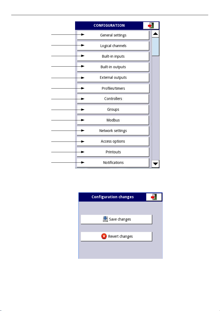
User Manual For - CONTROLLER/DATA RECORDER MultiCon CMC-99/141
Chapter 7.7
Chapter 7.8
Chapter 7.9
Chapter 7.10
Chapter 7.11
Chapter 7.12
Chapter 7.13
Chapter 7.14
Chapter 7.15
Chapter 7.16
Chapter 7.17
Chapter 7.18
Chapter 7.19
Fig. 7.29. Main menu selection panel
Fig. 7.30. Save / revert changes window
57
Page 58
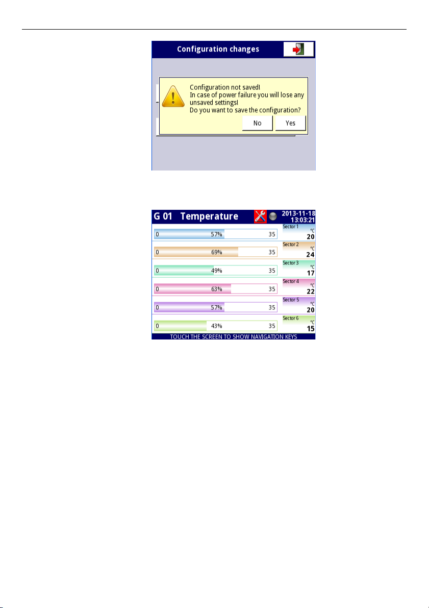
User Manual For - CONTROLLER/DATA RECORDER MultiCon CMC-99/141
Fig. 7.31. Warning message about unsaved configuration
Fig. 7.32. Example of unsaved configuration screen view
58
Page 59
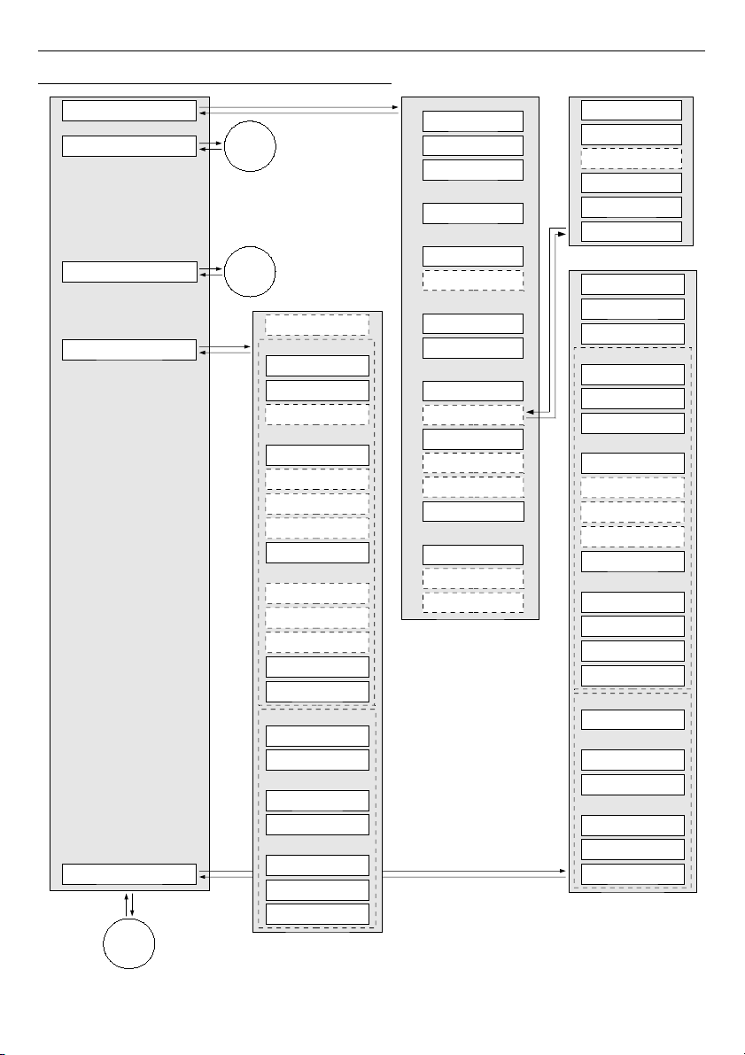
User Manual For - CONTROLLER/DATA RECORDER MultiCon CMC-99/141
7.6. CONFIGURATION MENU STRUCTURE
59
Built-in outputs
General settings
Input channels
Name
Mode
Alarm state
Level
Lower level
Upper level
Hysteresis
Source
ON delay
OFF delay
Min. ON time
Min. OFF time
Timing
Levels
Binary output
Analog outputs
Lower level
Upper level
Source
Lower level
Upper level
Alarm level
Output levels
Input levels
Level mode
Period
Unit
Display mode
Displayed group
Display time
Add a new view
Delete this view
Move to pos.
External outputs
Mode
Alarm state
Level
Lower level
Upper level
Hysteresis
Source
ON delay
OFF delay
Min. ON time
Min. OFF time
Timing
Levels
Binary output
Analog output
Lower level
Upper level
Source
Lower level
Upper level
Alarm level
Output levels
Input levels
Device
Output channel
Level mode
Comm. port
Date and time
Language
Basic
Backlight
Mode
Display mode
Displayed group
Change mode
Display time
Triggering source
Change timeout
LCD screen
Initial view
Automatic view change
Screen saver
Brightness
Setup list
Triggering mode
Remote shutdown
Mode
Triggering source
Delay
Reg.num. display.
1
3
Built-in inputs
2
Page 60
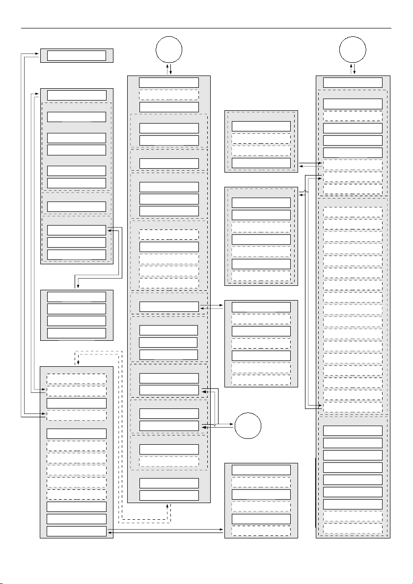
User Manual For - CONTROLLER/DATA RECORDER MultiCon CMC-99/141
60
Reset now
Reset mode
Strobe mode
Counting direction
Reset source
Strobe source
Direction source
Totalizer
Wire compensation
Compensation mode
Compensation
Actual temperature
Compensate
Decay constant
Output unit
Input unit
Input value
Output value
Point 2
Input value
Output value
Point 1
Scaling = linear
Scaling = offset
Value to add
Output unit
Num. of points
Edit points
Scaling = user char.
Scaling
Configure scaling
Filter type
Filter conf.
Processing
Format
Off-state text
Graph low
Graph high
On-state text
Precision
Displaying
Digits
Dormat pattern
Channel highlight
Name
Min. simulated val.
Max. simulates val.
Period
High state time
Source = Demo
Unit
Mode
Low limit
High limit
Rise time
Unit
Low limit
High limit
Mode
Source = analog input
Wire compensation
Totalizer
Base unit
Offset
Zero time
Source = digital input
Filter
Reset now
Counting mode
Reset mode
Prog. inp mode
Low limit
High limit
Unit
Base unit
Mode
Function mode
Filter time
Totalizer
Start/Stop inp. trig.
Reset source
Prog. inp. trig.
2
1
Output value
Input value
Add point
Delete point
Source X
Function
Type of source Y
Source Y
Type of source X
X error handling
Unit
Name
Mode
Unit
Source
Configure source
Function
Controller num.
Feedback channel
Mode = Controller
Set point channel
Mode = Math function
Mode = Hardwaer input
Source
Mode = Hard.out. monitor
Edit button
Mode = Set point value
Mode = Modbus
Port
SLAVE device
Device input
Source
Configure source
Mode = Profile/timer
Set point value
Mode
Latch
Triggering source
Source
Configure source
Mode = P/t (cycle counter)
Edit range low
Edit range high
Button mode
Source
Mode = Data from other ch.
Quantity
4
Trig. Hold time
Mode
Trigger
Alarm level
Blink period
Color
Page 61
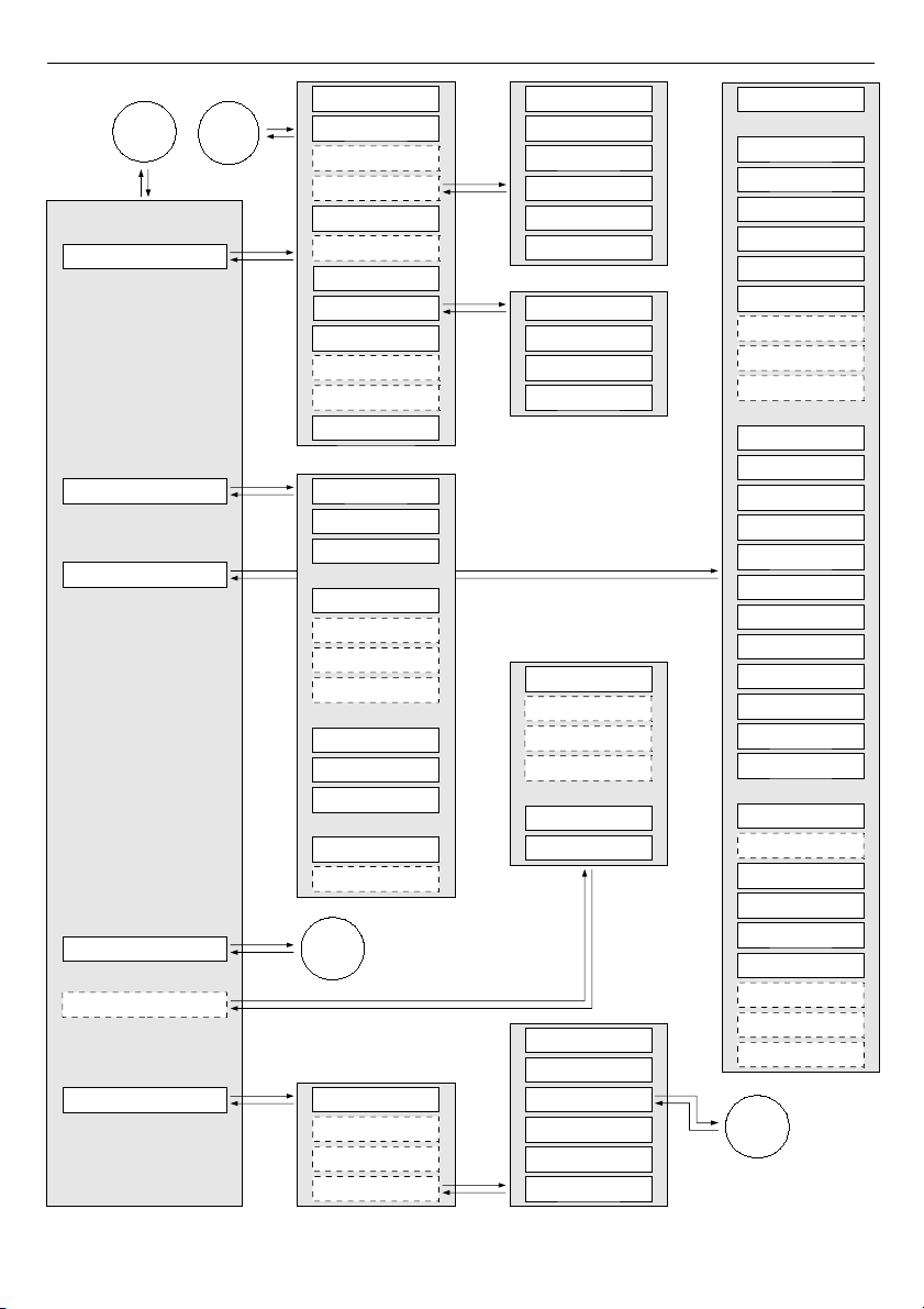
User Manual For - CONTROLLER/DATA RECORDER MultiCon CMC-99/141
61
Groups
Access options
Network settings
Profiles/times
Controllers
Modbus
Controller name
Mode
P coefficient
I coefficient
D coefficient
Differentiated signal
Dead zone
Offset
Low output limit
High output limit
Controller parameters
Controller output
Controller output
Init type
Initial output
Group
Name
Charts
Bars
Line width
Time scale
Background
Slot 1
Slot 2
Slot 3
Slot 4
Slot 5
Slot 6
Display option
Logging options
Channels
Mode
Description
Alternative mode
Besa period
Base unit
Alternative unit
Alternative source
Alternative period
Rotation direction
Offset
Labels
Theme
Theme
Theme
Theme
Theme
Theme
Triggering source
3
Months
Days
Week days
Hours
Minutes
Seconds
Name
Triggering mode
Triggering times
Idle value
Section list
Looping
Triggering source
Return to possition
Pause mode
Pause source
Loop count
Looping source
Shape
Duration
Final value
Unit
DHCP
IP address
Default gateway
Subnet mask
Screen number
IP address
Remote display
5
6
Access timeout
Access mode
Users list
Access pasword
Permissions
Name
Access dongle
Password
Assign dongle
Remove dongle
4
Page 62
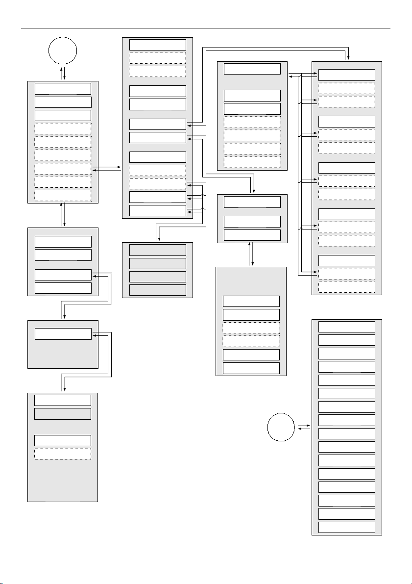
User Manual For - CONTROLLER/DATA RECORDER MultiCon CMC-99/141
62
Value register
Decimal point
-HI- register
-HI- state
Channel value
Channel status '-HI-'
-LO- register
-Lo- state
Channel status '-LO-'
-WAIT- register
-WAIT- state
Channel status '-WAIT-'
-ERR- register
-ERR- state
Channel status '-ERR-'
Dec.point register
-HI- value
-LO- value
-WAIT- value
-ERR- value
Register type
Write mode
32-bit reading
Data shift
Data format
Data mask
Register number
Ordering
Device type
Save device templ.
Load device templ.
Device templates
Load device templ.
Device name
Output list
Input list
Device channels
Max. block size
Blocks config.mode
Register blocks
Block list
Avail. input blocks
Avail. output blocks
Block type
Register size
Last register
First register
Mode
Baud rate
Request retials
SLAVE devices
Request timeout
Format
SLAVE settings
Interval
Address
5
Edit buttons
General settings
Built-in outputs
Profiles/timers
Built-in inputs
Controllers
Logical channels
Groups
Modbus
External outputs
Network settings
Logging files
Configuration files
Enter licence key
Firmware update
Remote display
Register type
Write mode
32-bit reading
Data shift
Data format
Data mask
Register number
Ordering
Output active
Output register
Control type
Channel value
Load device templ.
Save device templ.
Avail. output blocks
Output list
Device templates
Device channels
Value register
Status register
Dec.point register
Log. ch.
Register type
Write mode
32-bit reading
Data shift
Data format
Data mask
Register number
Ordering
6
Page 63
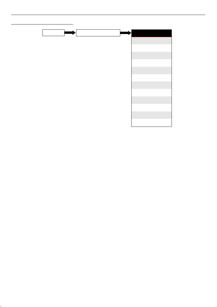
User Manual For - CONTROLLER/DATA RECORDER MultiCon CMC-99/141
7.7. GENERAL SETTINGS
The
General settings
menu allows to configure user interface display settings, the default
screen when the device powers on and automatic view change settings.
The parameters of the
General settings
menu are:
–
Basic
parameter block – this block includes two parameters:
•
Language
- this parameter allows the user to select the language, available
languages are: English, Polish, Spanish, German, Russian, French, Czech,
Romanian and Hungarian.
•
Date and time
- this parameter allows the user to set the current date and time,
•
Time zone
– parameter which should contain time zone where the device works
which allows to properly correct date and time in the device,
•
Reg. num. displaying
- this parameter allows to change mode of displaying the
Register addresses for
Logical channel
and
External output
menu. Two
formats are available:
◦
hexadecimal
- the registers are displayed in hexadecimal format. To
indicate that data has a hexadecimal format, the letter 'h' is added at the
end - for example, 12h (0x12),
◦
decimal
- the registers are displayed in decimal format (without any marker)
e.g. 123
–
LCD screen
parameter block:
•
Backlight
- this parameter allows the user to set the level of the LCD backlight.
Available levels are:
20%
(least backlight),
40%
,
60%
,
80%
,
100%
(the most
backlight),
–
Screen saver
parameter block - these parameters can reduce backlight level of the
LCD screen (or make it completely blank) during normal operation, i.e. when the
user does not touch the screen for a set time. This block has two parameters:
•
Mode
- this parameter has the following options:
63
Device configuration
MENU
General settings
Logical channels
Built-in inputs
Built-in outputs
External outputs
Profiles/timers
Controllers
Groups
Modbus
Network settings
Access options
Printouts
Notifications
Page 64

User Manual For - CONTROLLER/DATA RECORDER MultiCon CMC-99/141
◦
disabled
- this option turns off screen savers, the LCD screen is illuminated
at all times according to parameter settings:
Backlight
(see above
Screen
saver
parameter block )
◦
1min, 5min, 10min, 30min
,
•
Brightness
- this parameter is hidden for
Mode = disabled
, in the other modes
(
1min, 5min, 10min, 30min
) this parameter is visible, the user can change the
brightness level of the LCD screen after time set in parameter
Mode
elapses.
The options are: 0% (screen blank),
20%, 40%, 60%
,
–
Initial view
parameter block - allows the user to set the initial display screen on the
LCD screen when the device is turned on, this block includes two parameters:
•
Display mode
- select the presentation of data in the displayed group (see
parameter:
Displayed group
). For possible modes see
Chapter 6.3.3. Data
panels
, and
Chapter 7.14. GROUPS
,
•
Displayed group
- selects a group displayed at startup. If
Display mode
is
chosen as
many groups
, parameter
Displayed group
selects the first of five
following groups displayed on the screen (
many group
mode presents 5 groups
in one window). For example, when the user sets
Display group
as
Group 8
then the unit will display: starting from the left side of: Group 8 -> Group 9 ->
Group 10 -> Group 1 -> Group 2,
–
Automatic view change
parameter block - this parameter block allows the user to
set the display to change every time period. The parameters of this block include:
•
Change mode
- this parameter has the following options:
◦
disabled
- no changes in the display. For this mode the remaining
parameters in this block are not visible,
◦
change modes
- allows the user to automatically change the displayed
mode,
◦
change groups
- allows the user to automatically change displayed group,
◦
detailed list
- allows to automatically change displayed views defined by
the user,
•
Triggering mode
– this parameter has the following options:
◦
by time
– it enables to change displayed view at fixed time intervals,
◦
from log. channel
– changes displayed view depending on value in
selected logical channel. If value in this channel is less than 1, displayed
view number is 1, if value in this parameter equal or more than 1 but less
than 2 displayed view number is 2, and so on. The last defined view does
not has the upper limit.
•
Display time
– this parameter is visible for the
Change mode: change modes
,
change groups
– duration (set in seconds) for each screen,
•
Triggering source
– this parameter is visible for the
Change mode
:
change modes
,
change groups
, and for the
Triggering mode
:
from log. channel
; it allows the user to choose logical channel from the list,
which value will sets up the displaying view,
•
Change timeout
– this parameter determines the time from the device startup
or manually change of the view to first automatic view change,
•
Setup list
– this button is visible for
Change mode
parameter setted as
detailed list
, this parameter is described below in this
Chapter
,
64
Page 65
User Manual For - CONTROLLER/DATA RECORDER MultiCon CMC-99/141
–
CSV Format settings
parameter block – contains parameters which are related with
creating and sending CSV files,
•
Decimal separator
– selects decimal separator in CSV files for numeric values,
◦
dot
– decimal separator is a dot and a comma will separate all fields in CSV
files,
◦
comma
– decimal separator is a comma and a semicolon will separate all
fields in CSV files,
–
Remote shutdown
parameter block – allows to set automatic shutdown of the
device,
•
Mode
– turns on and off shutdown from logical channel,
◦
disable
– remote shutdown is off,
◦
from log. channel
– remote shutdown is on,
•
Triggering source
– contains the logical channels list, where selected one will
be source for the remote shutdown; the shutdown procedure will start each time
when signal in selected channel will change from value ≤
0
to value
> 0
,
•
Delay
– settable time that will pass before the device will shutdown; this
procedure will be stopped if during this time:
◦ signal in
Triggering source
parameter will drop to ≤
0
value,
◦ the user will press
cancel
button on the screen,
When device starts or when in
Remote shutdown
parameter block has been
made any changes and in selected channel in
Triggering source
parameter is
value greater than 0, the shutdown procedure won't start. To start shutdown
procedure, value in this channel must change to value equal or lower than 0 and
then to value greater than 0.
Setup list
parameter
After pressing the
Setup list
button the user enters the
View
menu allowing the creation of
1
to 20 views.
Arrows placed in the upper right corner of the screen allow you to
move to the next view. The middle button allows you to directly select a
particular view.
Parameters of
View
menu are:
–
Display mode
- this parameter allows the user to select the presentation of the data
in the displayed group (see parameter:
Displayed group
). For possible modes see
Chapter 6.3.3. Data panels
and
Chapter 7.14. GROUPS
,
–
Displayed group
- allows the user to select a group displayed at startup. If the
Display mode
is chosen as
many groups
, parameter
Display group
selects the
first of five following groups displayed on the screen (mode many group presents 5
groups in one window). For example, when setting the parameter to
Display group=Group 8
then the display will show: starting from the left side of:
Group 8 -> Group 9 -> Group 10 -> Group 1 -> Group 2,
–
Display time
- this parameter is visible for the
Triggering mode: by time
, it sets the
duration (in seconds) of the selected view,
–
Add a new view
button - adds a new view to the list
–
Delete this view
button - deletes selected view from the list,
–
Move to position
- this parameter allows the user to move the current view to the
appropriate position,
65
i
Page 66

User Manual For - CONTROLLER/DATA RECORDER MultiCon CMC-99/141
Example:
Steps to create four views are as follows:
1.
In the Change mode parameter select detailed list,
2.
Press the
Setup list
button and enter the
View
menu,
3.
Set parameters for a first View,
Arrows placed in the upper right corner of the screen allow you to
move to the next view. The middle button allows direct selection of a
particular view.
4.
To add or delete further views use the
Add a new view
button or
Delete this view
button, respectively,
5.
When the user wants to add a view between the existing views, e.g. between views 2
and 3, user can choose two ways:
•
select the 2nd view (by the arrows in the upper right corner of the screen) and
then add a new view by clicking the
Add a new view
button,
•
after adding new view on the end of the list, the
Move to position
parameter set
as 3 value,
6.
When finished, the user can see all the defined views by clicking t he middle button
between the arrows in the upper right corner of the screen,
66
Page 67
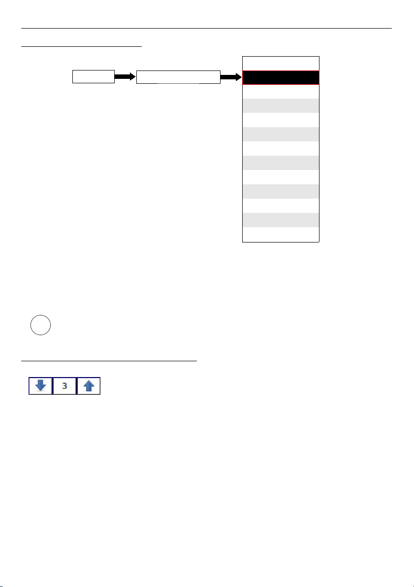
User Manual For - CONTROLLER/DATA RECORDER MultiCon CMC-99/141
7.8. LOGICAL CHANNELS
The
Logical channels
menu is used to configure the logical channels. Channels can be
treated as input data for outputs, controllers or other
Logical channels
and can be collected
into
Groups
for simultaneous display. To see a detailed definition of
Logical Channel
see
Chapter 5.1.1. Logical channels
.
To enter directly into the configuration menu of particular channel, press and hold
on the screen over the channel data panel for a few seconds (see option
(1)
in the
Fig. 6.5
). If the password is set (see
Chapter 7.17. ACCESS OPTIONS
) then the
user has to enter the password before entering the configuration.
7.8.1. Logical Channels - General settings
Arrows placed in the upper right corner of the screen allow you to
switch between a succession of logical channels. The middle button
allows you to directly select a specific logical channel from the list.
The parameters of a logical channel depends on the
Mode
of the logical channel. The
Logical channel
has modes:
– disabled
– Hardware input
– Hardware output monitor
– Modbus
– Set point value
– Math function
– Controller
– Profile/timer
– Profile/timer (cycle counter)
– Data from other channel
A detailed description of the models is in the following chapters.
67
i
Device configuration
MENU
General settings
Logical channels
Built-in inputs
Built-in outputs
External outputs
Profiles/timers
Controllers
Groups
Modbus
Network settings
Access options
Printouts
Notifications
Page 68

User Manual For - CONTROLLER/DATA RECORDER MultiCon CMC-99/141
The channel for
Mode=disabled
has only one parameter - the
name
of the channel. In other
modes the
Logical channels
are
active
and may affect the processing and control data.
Parameters and blocks of parameters common for
active Logical channels
:
–
Name
- it gives the name to the logical channel,
–
Unit
- is related with a data source of channel,
• for
Built-in modules
it will automatically use a default
Unit
,
• for
Mode=Set point value
and
Mode=Controller
the
Unit
can be defined freely,
directly in the
Logical Channel
menu,
• for other modes the
Unit
can be added only using the
Scaling
parameter (see
below in this
Chapter
for discussion about the
Scaling
parameter),
–
Mode
- in this parameter the user selects the source of the data for logical channel .
It is possible to select one of ten modes:
• disabled
,
• Hardware input
- see Chapter
7.8.2
,
•
Hardware output monitor
- see Chapter
7.8.3
,
•
Modbus
- see Chapter
7.8.4
,
•
Set point value
- see Chapter
7.8.5
,
•
Math function
- see Chapter
7.8.6
,
•
Controller
- see Chapter
7.8.7
,
•
Profile / timer
- see Chapter
7.8.8
,
•
Profile/timer (cycle counter)
– see Chapter
7.8.9
,
•
Data from other channel
– see Chapter
7.8.10
,
–
Latch
parameter block - allows user to set the
latch function
which will hold the last
value of a channel; this block has the following parameters:
•
Mode
- this parameter allows the user to choose how to trigger the latch
function; there are 2 options:
◦
disabled
- the latch function is disabled,
◦
from logic channel
- the latch function is activated depending of the value
of channel selected in the
Triggering source
parameter,
•
Triggering source
- this parameter is only visible if user sets
Mode=from logic channel
; using this parameter the user chooses a logical
channel which is the triggering source of the latch function (when the value of
triggering channel is ≤0 the latch is
active
, for a value >0 latch is
disabled
),
During device restart, the logical channels, which have the latch function enabled
have value: '0' and on the LCD screen blinking dashes '
----
' appear in place of the
value.
–
Processing
parameter block - is used for scaling and filtering data (for explanation
see below)
–
Displaying
parameter block - for these parameters the user selects the format and
range of the data displayed on the screen. For more information about
Displaying
parameters see below in this
Chapter
.
68
i
Page 69
User Manual For - CONTROLLER/DATA RECORDER MultiCon CMC-99/141
Processing
parameter block
For this block the parameters are:
–
Scaling
,
–
Filter type
,
To enter the scaling menu press the button next to the
Scaling
label. The menu has the
following options:
a)
disabled
– no scaling of input data,
b)
linear
– after choosing this option, parameter appears:
•
Configure scaling
– submenu which allows the user to change unit in this
logical channel and rescale value using two points. This submenu contains
following options:
◦
Input unit
– read only parameter, it displays unit of the logical channel
source,
◦
Output unit
– unit of rescaled data,
◦
Point 1
block contains following options:
–
Input value
– value of point 1 before scaling,
–
Output value
– value of point 1 after scaling,
◦
Point 2
block contains following options:
–
Input value
– value of point 2 before scaling,
–
Output value
– value of point 2 after scaling,
In MultiCon, linear scaling can be done in with table placed below, but slope and offset are
constant values and they should be determined by user earlier.
Input value Output value
Point 1 x
1
y1=slope*x1+offset
Point 2 x
2
y2=slope*x2+offset
Tab.7.2 The way to calculate the output value
Example:
The task is to rescale temperature from Centigrades, in which all of the MultiCon modules are
scaled, to degrees Fahrenheit. The formula, which should be used for this task is shown
bellow:
where:
TF – temperature in degrees Fahrenheit,
TC – temperature in Centigrades,
9/5 – slope,
32 – offset,
69
TF=1.8⋅TC32
Page 70
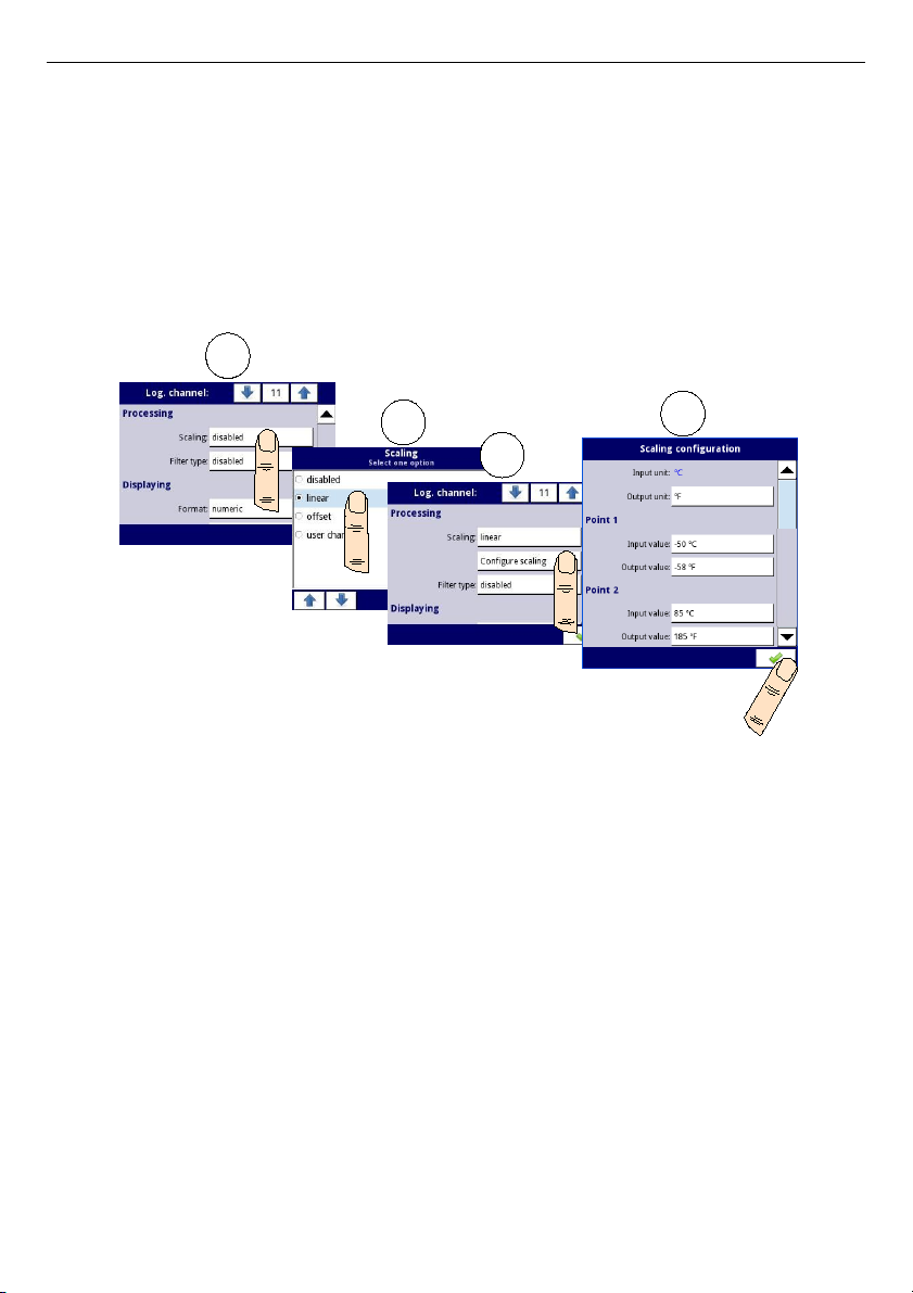
User Manual For - CONTROLLER/DATA RECORDER MultiCon CMC-99/141
Lets assume that our temperature range is from -50˚C to 85˚C (but this range is arbitrary). In
that case:
–
Scale
parameter set as
linear
,
– enter Configure scaling submenu:
•
in
Output unit
parameter write: ˚F,
•
in
Input value
parameter for
Point 1
block write:
-50
(which is low range limit),
•
in
Output value
parameter for
Point 1
block write:
-58
(according to the
formula),
•
in
Input value
parameter for
Point 2
block write: 85 (which is low range limit),
•
in
Output value
parameter for
Point 2
block write:
185
(according to the
formula),
Fig. 7.33. Example of scaling configuration
c)
offset
– after choosing this option, parameter appears:
•
Configure scaling
– function, which allows to add a constant value to input
value. It is given by formula:
In this function, there are following parameters:
•
Input unit
– read only parameter, it displays unit of the logical channel
source,
•
Value to add
– it defines offset value,
d)
user char.
- is defined as set of X-Y points. Number of the points is variable and may
be set from 2 to 20 points which make linear segments (see
Fig. 7.34
). After
choosing this option, parameter appears:
•
Configure scaling
– submenu which allows to define further points of the
user characteristic. There are following parameters:
◦
Input unit
– read only parameter, it displays unit of the logical channel
source,
◦
Output unit
– unit of rescaled data,
70
y=xoffset
1
2
3
4
Page 71
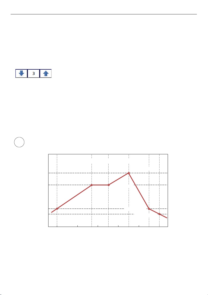
User Manual For - CONTROLLER/DATA RECORDER MultiCon CMC-99/141
◦
Num. of point
– read only parameter, in displays number of points that
currently are defined in characteristic,
◦
Edit points
– submenu that defines point in characteristic:
–
Input value
– point value before scaling,
–
Output value
– point value after scaling,
–
Add point
button – adds new point, behind currently displayed,
–
Delete point
button – deletes currently displayed point, parameter
is inactive when number of points in characteristic is 2,
The arrows placed in the upper right corner of the screen allows to
switch between points. The middle button allow direct selection of a
particular point from the list.
For 2 points the user characteristic works like a linear process (see subsection b)).
For more than 2 defined points the user characteristic is a composite of the line
characteristics therefore for input value
'x'
the user obtain an output value
'y'
which is
described by the relationship:
,where
'slope'
and
'offset'
are coefficients of a segment contained between two points
(see
Fig. 7.34
), and
n = 1, 2 ..
is the number of the segment.
If the input exceeds the extreme
'x'
values of the designated points of
P
n
, the output
value is scaled by the functions defined at the extreme segments.
Fig. 7.34. Example of user characteristic
71
y=slopen⋅xoffset
n
i
Input value
Output value
P1(X1=0, Y1=0)
0 4 8
12
0
25
32
-3
P2(X2=7, Y2=25)
P3(X3=10, Y3=25)
P4(X4=14, Y4=32)
P5(X5=18, Y5=0)
P6(X6=20, Y6=-3)
5-interval characteristics
16 20
Page 72
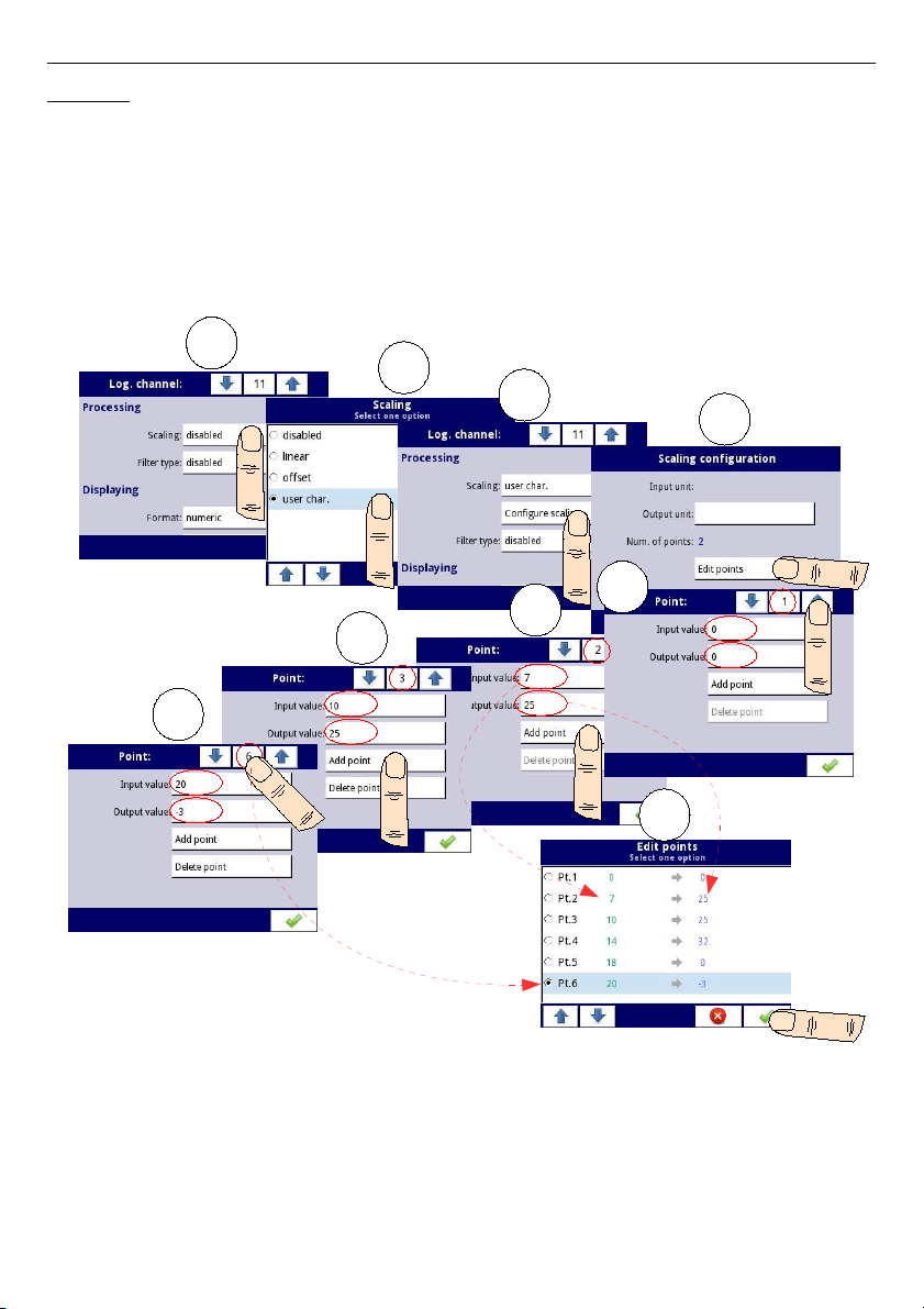
User Manual For - CONTROLLER/DATA RECORDER MultiCon CMC-99/141
Example:
Steps to create a user characteristic consisting of 6 points (like on
Fig. 7.34
):
1.
Press the button next to the
Scaling
label and select
user characteristic
option
(point
(1)
and
(2)
in
Fig. 7.35
).
2.
Press the
Configure scaling
button and enter the
Scaling configuration
menu
(point
(3)
in
Fig. 7.35
).
3.
If you want to create an output
Unit
, which replaces the input unit, or if no unit is
defined on the input, press the button next to
Output Unit
label.
4.
Press the
Edit points
button (point
(4)
in
Fig. 7.35
) and go to
Edit points
menu.
Fig. 7.35. Configuring the user characteristic
For
Point 1
set input and output value (point
(5)
in
Fig. 7.35
).
5.
Switch to
Point 2
by using the arrow keys and there also set the value of input and
output (point
(6)
in
Fig. 7.35
).
6.
To
add
or
delete
points the user should use the
Add point
button or
Delete point
button, respectively,
72
1
2
3
4
5
6
7
8
9
Page 73
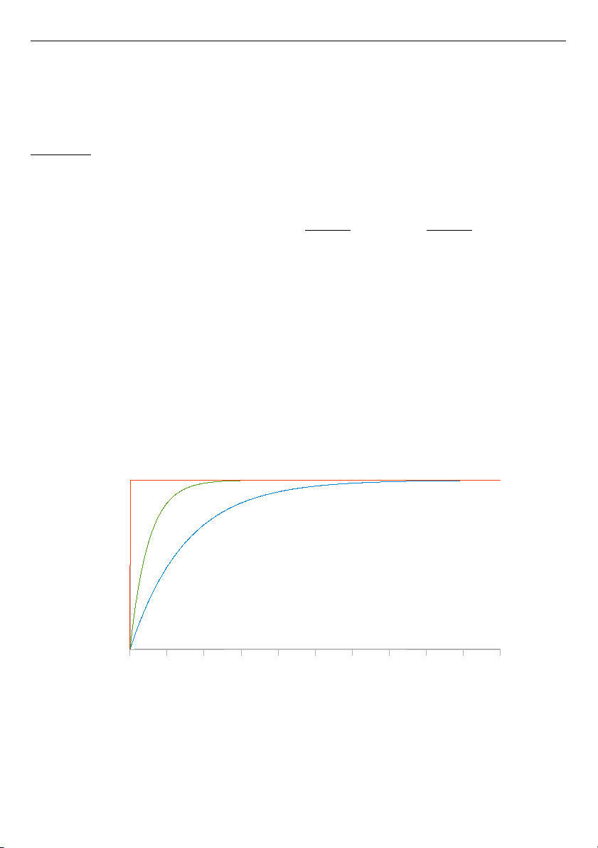
User Manual For - CONTROLLER/DATA RECORDER MultiCon CMC-99/141
7.
When the user wants to add a new point between the existing point e.g. between 5
and 6, select the edit
Point 5
and then add a new point by press the
Add point
button.
8.
At the end we check all the points defined by clicking the middle button between the
arrows in the upper right corner of the screen (point
(8)
and
(9)
in
Fig. 7.35
).
Filter type
The
Filter type
parameter has options:
–
disabled
- filtering of the input value is turned off,
–
smoothing
- this option enables a filter that is expressed by the formula:
,where
n
- number of sample, where n = 1, 2, 3 ...,
Y
n
- output value for n-th sample,
Y
n-1
- output value for n-1 sample,
X
n
- input value for n-th sample,
w
- time constant in seconds, this filter coefficient is defined by the user from the
Decay constant
parameter (a value of
'0'
for the filter is turned off),
0.1 sec.
- sample time,
After selecting
smoothing
option in
Filter type
parameter new button is available -
Filter
configuration
which allows the user to enter a time constant with the
Decay constant
parameter (see above filter formula).
Fig. 7.36. Example of the input signal (red chart), filtered signal for the time constant = 5s
(green chart) and time constant = 15s (blue chart)
73
Yn=Xn⋅1−e
−0,1sek.
w
Y
n−1
⋅e
−0,1sek.
w
0 10 20 30 40 50 60 70 80 90 100
10
15
time [s]
output value
Page 74
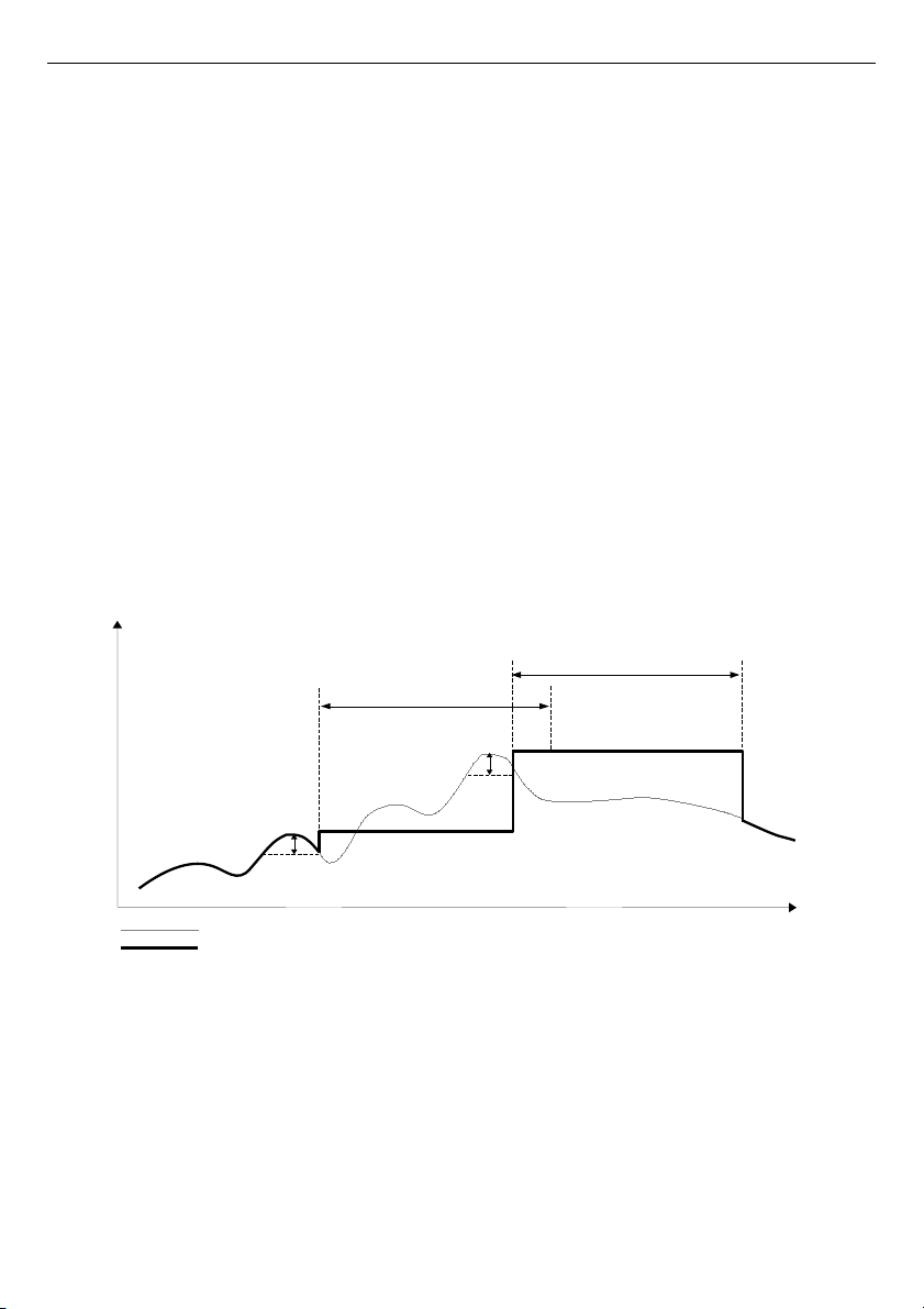
User Manual For - CONTROLLER/DATA RECORDER MultiCon CMC-99/141
–
peak detect
– function which allows to detect and visualize peak values in measured
signal. Detection of the peak value can be done if the measured signal raises and
drops (or the opposite) by value, which is settable by the user. Next, the detected
value can be hold for settable by user period of time. If during the time when peak is
detected, new peak is detected, then the peak value is updated and the time of hold
is reset. When this time will elapse, or no peak is detected, the device will display
current value of the signal (see
Fig. 7.37
).
After selecting this option,
Filter conf.
button will appear which contains
configuration parameters of this filter:
•
Mode
– allows to choose filter work mode,
◦
peaks
– function detects highest values in logical channel
◦
valleys
– function detects lowest values in logical channel,
•
Value
– the peak will be detected when signal value will drop or rise for value in
this parameter,
•
Hold time
– the time which the detected peak will be hold, under condition that
there will be no new peak detected,
•
Reset mode
– turns on and off reset of the peak value from logical channel,
◦
disabled
– reset form logical channel is off,
◦
from log. channel
– allows to select a logical channel, in which value that
is higher than 0, will reset the peak detect,
•
Reset source
– it contains the logical channels list, where selected on will be
for the peak detect source of reset,
Fig. 7.37. Process of peak detection
74
”Hold time”
measure
time
”Hold time”
”Value”
”Value”
real measurement result
display value
Page 75
User Manual For - CONTROLLER/DATA RECORDER MultiCon CMC-99/141
Displaying
parameter block
The constant parameters of
Displaying
block are:
–
Format
- the logical channel data formats, which are:
•
numeric
– value in this channel is displayed as a number,
•
binary
– only for values:
'0'
for low state and
'1'
for high state,
•
time
– value in this channel is displayed as a time. Logical channel in time
Format will always considers its value as a number of seconds and base on this
and settings in
Time pattern
parameter, the logical channel will calculate the
value to display,
–
Time pattern
– this parameter occurs only when
Format
parameter is set as
time
;
it allows user to define time pattern at his will. Only restrictions are that higher units
have to be before lower units and different units have to be separated by colon
character. Allowed is to create units which contains any number of digits. When user
creates a pattern which is forbidden, the device will detect it and set the pattern as
default.
–
Precision
– this parameter occurs when
Format
parameter is set as
numeric
or
time
, which specifies the precision to be displayed on the output value (see
Fig. 7.39
),
–
Off-state text
– this parameter occurs when
Format
parameter is set as
binary
,
when the input value is
≤ 0
the value is replaced by the text defined by the user,
default settings text is:
OFF
,
–
On-state text
- this parameter occurs when
Format
parameter is set as
binary
,
when the input value is >0 the value is replaced by the text defined by the user,
default settings text is: ON,
The text of
Off-state
and
On-state
can be:
• text with black font such as: ALARM, off, OK,
• text using numbers and special characters such as: ALARM_ #12
• text using font color and / or a background color for example:
• no text, only a rectangle with the selected color - the width of the rectangle on
the screen is defined by pressing the
Spacebar
(empty string), and the color of
the rectangle is the background color, for example:
–
Digits
- this parameter occurs when
Format
parameter is set as
numeric
, allowing
user to choose the part of the number that is to be the value of the logical channel
displayed on the screen,
75
Page 76
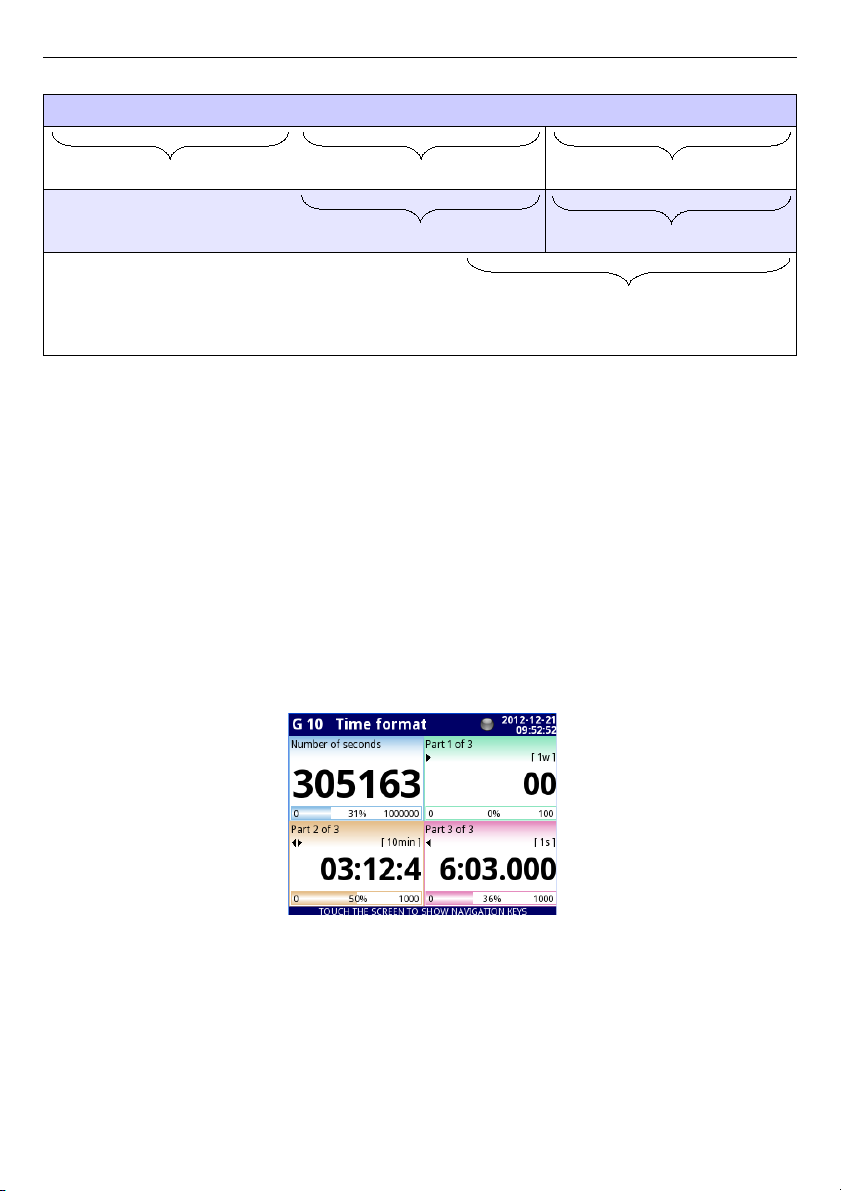
User Manual For - CONTROLLER/DATA RECORDER MultiCon CMC-99/141
Example of a number representing the value of the logical channel:
1 2 5 6 2 8 0 2 2 1 5 8 6 4 . 8 7 3
part 1 of 3 part 2 of 3 part 3 of 3
part 1 of 2 part 2 of 2
all digits
(limited ability to display up to
5 digits plus decimal point on the
screen)
– Available options for
Digits
parameter are:
•
all digits
– display all parts. With this option the number is limited only to
possibilities of the display;
•
part 1 of 2
- display the higher part of the number on the screen,
•
part 2 of 2
– display the lower part of the number on the screen,
•
part 1 of 3
– display the highest part of the number on the screen,
•
part 2 of 3
- display the middle part of the number on the screen,
•
part 3 of 3
- display the lowest part of the number on the screen,
For time Format in logical channel only 6 digits, three special signs (colons, dot), but not
more than eight signs and minus. Using Digits and Precision parameters, the device will
display time from youngest unit with maintaining all restrictions, see
Fig. 7.38
.
Minus signs is displayed only before the highest unit of the
Time Pattern
. When the
highest unit can not be displayed in logical channel, minus sign will not appear and value in
this channel will be considered as a positive value.
Fig. 7.38.Example of time Format view with Precision 0.000 and standard Time Pattern
[ww:dd:hh:mm:ss]
–
Graph
low - minimum range value for graphs, bars, needle dials and percentage
bars (see
Fig. 7.39
),
–
Graph high
- maximum range value for graphs, bars, needle dials and percentage
bars (see
Fig. 7.39
),
76
Page 77
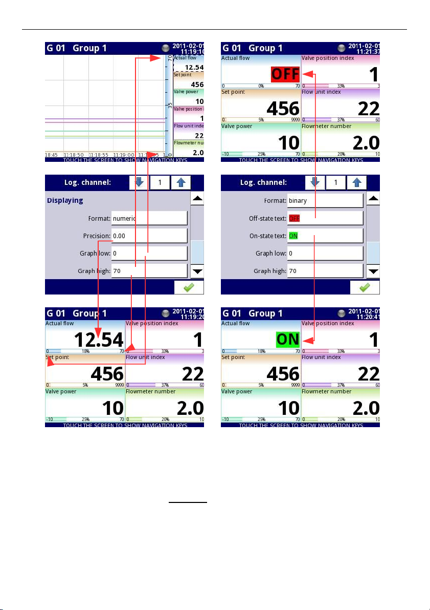
User Manual For - CONTROLLER/DATA RECORDER MultiCon CMC-99/141
Fig. 7.39. Input channels menu – 2 different kinds of Displaying parameters
To calculate percentage which will be displayed on the indicator, the device is using
following equation:
where:
R – result
V – value in logical channel
Lo – Graph low value in logical channel
Hi – Graph high value in logical channel
77
R=
V −Lo
Hi−Lo
⋅100 %
Page 78
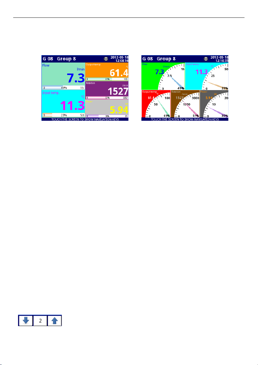
User Manual For - CONTROLLER/DATA RECORDER MultiCon CMC-99/141
–
Channel highlight
– block of parameters, used to change background color
and its mode in the logical channel. User can set up to three different variants of
highlights, depending to event weight, which should trigger highlight in this
channel.
Fig. 7.40 Example of logical channel highlights
In
Channel highlight
user can set following parameters:
•
Mode
– is used to change the way of highlight displaying. There are three
options: disabled, permanent, blinking,
•
Blink period
– it appears, when
Mode
parameter is set on
blinking
. It
defines the blink period of the highlight,
•
Trig. hold time
– it is a minimal time, during which, the highlight variant will
be generated, even if the generating signal will disappear. However, user
should pay attention on the highlight hierarchy. If the highlight variant with
higher number is active, and the highlight variant with lower number will
appear, generated will the one with lower number, even if the Trig. hold time
of the first one will not expire,
•
Trigger
– using this parameter, user can choose the logical channel, which
will be the source of triggering for the channel highlight. When in source
channel, there is a value
≤ 0
, then highlight is inactive, and when there is a
value > 0, then highlight is active,
•
Alarm level
– in this parameter, user can choose is the highlight variant
active, when channel selected in
Trigger
parameter, will returns an
Err, Hi
or Lo alarm:
◦
no highlight
– selected highlight variant will not be active while alarm
state in logical channel,
◦
highlight forced
– selected highlight variant will be active while alarm
state in logical channel,
•
Color
– in this parameter, user can set the background color and font color
of the highlight variant,
Using arrows placed in the upper right corner of the screen, user can
choose highlight variant, which he wants to configure. The middle
button allows direct selection of a specific variant from the list.
78
Page 79
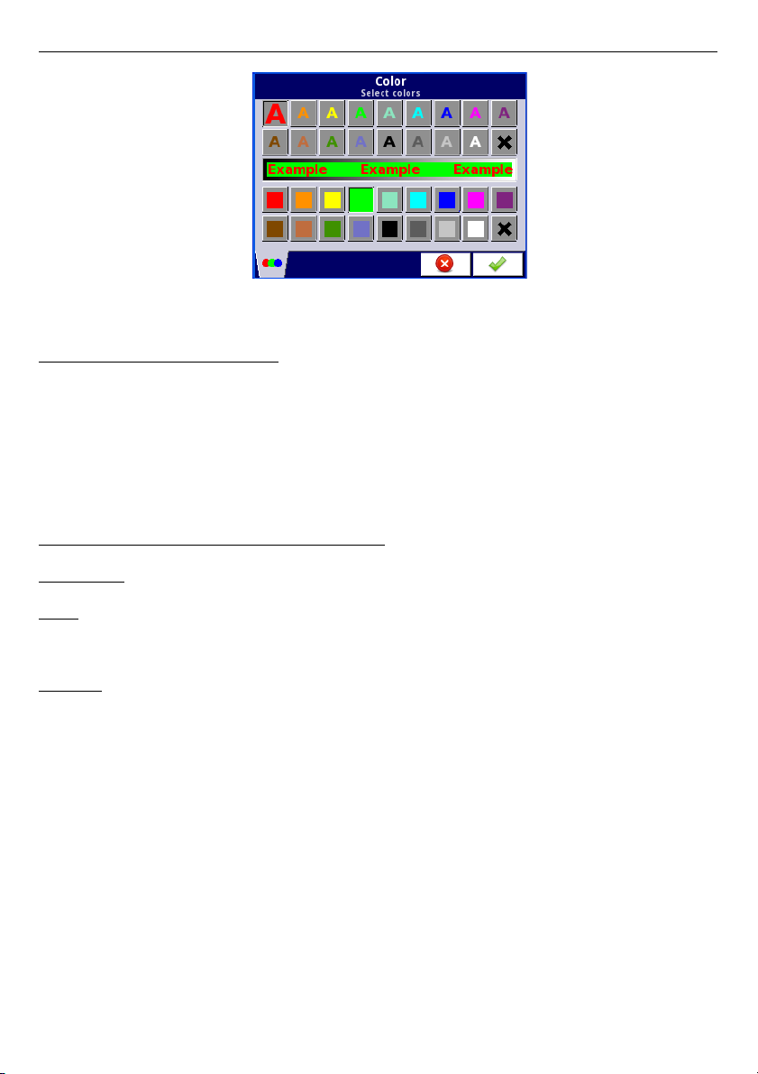
User Manual For - CONTROLLER/DATA RECORDER MultiCon CMC-99/141
Fig. 7.41 Color edit dialog
Comments regarding the display:
– The precision of the displayed data can be set in the device with any accuracy (up to
4 decimal places), it must be remembered that the resolution and accuracy of
external sensors connected to the device is finite, and usually not better than 0.1%.
– User should pay attention on the highlight hierarchy. If there are two or three variants
of highlight generated at once, one with the lowest number will be displayed.
– The time scale is common for the entire
Group
and can be set in the
Groups
menu
(see
Chapter 7.14. GROUPS
).
Examples of Channel highlight configuration.
Example 1:
Task:
User's task is to set blinking highlight on alarm channel, which will be active when
measured current value is too high or too low.
Solution:
After connecting all measuring devices and configuring them in MultiCon, we can start to
configure the highlights.
To complete the task, we will need to configure 4 logical channels and 1 virtual relay:
a) Channel with measured current value.
b) Channel with overhead alarm threshold .
c) Channel with bottom alarm threshold.
d) Channel with highlight alarm.
e) Virtual relay which will define, when is time to activate the alarm.
Logical channel 1: Measuring the current:
–
In
Name
parameter write:
Current value
,
–
Mode
parameter set as:
Hardware input
,
–
Source
parameter set as:
Inp.A1 : Current
,
–
Precision
parameter set as:
0.00
,
–
In
Graph low
parameter write: 0,
–
In
Graph high
parameter write: 22,
–
All other parameters should be set as default,
79
Page 80

User Manual For - CONTROLLER/DATA RECORDER MultiCon CMC-99/141
Logical channel 2: Overhead alarm threshold:
–
In
Name
parameter write:
Overhead alarm threshold
,
–
Mode
parameter set as:
Set point value
,
–
Edit button
parameter set as:
enabled
,
–
In
Unit
parameter write: mA,
–
Precision
parameter set as:
0.00
,
–
In
Graph low
parameter write: 0,
–
In
Graph high
parameter write:
22
,
–
All other parameters should be set as default,
Logical channel 3: Bottom alarm threshold:
–
In
Name
parameter write:
Bottom alarm threshold
,
–
Mode
parameter set as:
Set point value
,
–
Edit button
parameter set on:
enabled
,
–
In
Unit
parameter write: mA,
–
Precision
parameter set as:
0.00
,
–
In
Graph low
parameter write: 0,
–
In
Graph high
parameter write: 22,
–
All other parameters should be set as default,
Logical channel 4: Alarm displaying:
–
In
Name
parameter write:
Alarm state
,
–
Mode
parameter set as:
Hardware output monitor
,
–
Source
parameter set as:
Out.V1 : Virtual relay
,
–
Format
parameter set as:
binary
,
–
In
Off-state text
parameter write:
No alarm
,
–
In
On-state text
parameter write:
ALARM!
,
–
In
Graph low
parameter write: 0,
–
In
Graph high
parameter write: 22,
–
Now we go to
Channel highlight
submenu:
•
Highlight color
parameter set as: 1,
•
Mode
parameter set as:
blinking
,
•
In
Blink period
parameter write: 1,
•
In
Trig.hold time
parameter write: 1,
•
Trigger
parameter set as logical channel that we currently configuring (in
this task, it will be Logical channel 4 named
Alarm state
),
•
Alarm state
parameter set as:
no highlight
,
•
Now, go to
Color
parameter and set font color (at the top of screen) and
background color (at the bottom of the screen),
•
For
Highlight color 2
and 3, set
Mode
parameter as
disabled
,
Virtual relay V1: Defining, when is time to activate the alarm:
–
Mode
parameter set as:
outside range
,
–
Source
parameter set as logical channel named as
Current value
,
–
Alarm state
parameter set as:
immed. ON
,
–
Level mode
parameter set as:
channel
,
–
Lower level
parameter set as logical channel named as
Overhead alarm
threshold
,
–
Upper level
parameter set as logical channel named as
Bottom alarm
threshold
,
–
All other parameters should be set as default,
80
Page 81

User Manual For - CONTROLLER/DATA RECORDER MultiCon CMC-99/141
Example 2:
Task:
User's task is to set blinking highlight on temperature channel, which will be activated on
three different levels.
Solution:
After connecting all measuring devices and configuring them in MultiCon, we can start to
configure the highlights.
To complete the task, we will need to configure 7 logical channels:
a) Channel with first level.
b) Channel with second level .
c) Channel with third level.
d) Channel that will tell when will first alarm appear.
e) Channel that will tell when will second alarm appear.
f) Channel that will tell when will third alarm appear.
g) Channel where the temperature is measured, and the alarms will appear.
Logical channel 1: First level:
–
In
Name
parameter write:
First level
,
–
Mode
parameter set as:
Set point value
,
–
Edit button
parameter set as:
enabled
,
–
In
Unit
parameter write: °C,
–
Precision
parameter set as:
0.0
,
–
In
Graph low
parameter write:
-50
,
–
In
Graph high
parameter write: 85,
–
All other parameters should be set as default,
Logical channel 2: Second level:
–
In
Name
parameter write:
Second level
,
–
Mode
parameter set as:
Set point value
,
–
Edit button
parameter set as:
enabled
,
–
In
Unit
parameter write: °C,
–
Precision
parameter set as:
0.0
,
–
In
Graph low
parameter write:
-50
,
–
In
Graph high
parameter write:
85
,
–
All other parameters should be set as default,
Logical channel 3: Third level:
–
In
Name
parameter write:
Third level
,
–
Mode
parameter set as:
Set point value
,
–
Edit button
parameter set as:
enabled
,
–
In
Unit
parameter write: °C,
–
Precision
parameter set as:
0.0
,
–
In
Graph low
parameter write:
-50
,
–
In
Graph high
parameter write: 85,
–
All other parameters should be set as default,
Logical channel 4: Calculating the time of the first alarm,
–
In
Name
parameter write:
Calc. First level
,
–
Mode
parameter set as:
Math function
,
–
Click on the
Function
button,
•
Function
parameter set as:
X – Y
,
81
Page 82

User Manual For - CONTROLLER/DATA RECORDER MultiCon CMC-99/141
•
Source X
parameter set as logical channel where the temperature
measurement is shown,
•
Type of source Y
parameter set as:
channel
,
•
Source Y
parameter set as logical channel named as
First level
,
–
Precision
parameter set as
0.0
,
–
Graph low
parameter set as:
-50
,
–
Graph high
parameter set as: 85,
–
All other parameters should be set as default,
Logical channel 5: Calculating the time of the second alarm,
–
In
Name
parameter write:
Calc. Second level
,
–
Mode
parameter set as:
Math function
,
–
Click on the
Function
button,
•
Function
parameter set as:
X – Y
,
•
Source X
parameter set as logical channel where the temperature
measurement is shown,
•
Type of source Y
parameter set as:
channel
,
•
Source Y parameter
set as logical channel named as
Second level
,
–
Precision
parameter set as
0.0
,
–
Graph low
parameter set as:
-50
,
–
Graph high
parameter set as: 85,
–
All other parameters should be set as default,
Logical channel 6: Calculating the time of the third alarm,
–
In
Name
parameter write:
Calc. Third level
,
–
Mode
parameter set as:
Math function
,
–
Click on the
Function
button,
•
Function
parameter set as:
X – Y
,
•
Source X
parameter set as logical channel where the temperature
measurement is shown,
•
Type of source Y
parameter set as:
channel
,
•
Source Y
parameter set as logical channel named as
Third level
,
–
Precision
parameter set as
0.0
,
–
Graph low
parameter set as:
-50
,
–
Graph high
parameter set as: 85,
–
All other parameters should be set as default,
Logical channel 7: Temperature measurement:
–
In
Name
parameter write:
Temperature
,
–
Mode
parameter set as:
Hardware input
,
–
Source
parameter set as:
Inp.A4 : Intern.temp
,
–
Precision
parameter set as:
0.0
,
–
In
Graph low
parameter write:
-50
,
–
In
Graph high
parameter write: 85,
–
Now go to
Channel highlight
submenu:
•
Highlight color
parameter set as: 1,
◦
Mode
parameter set as:
permanent
,
◦
In
Trig.hold time
parameter write: 5,
◦
Trigger
parameter set as logical channel named
Calc. Third level
,
◦
Alarm state
parameter set as:
no highlight
,
◦
Now, go to
Color
parameter and set font color (at the top of screen)
and background color (at the bottom of the screen),
82
Page 83

User Manual For - CONTROLLER/DATA RECORDER MultiCon CMC-99/141
•
Highlight color
parameter set as: 2,
◦
Mode
parameter set as:
blinking
,
◦
In
Blink period
parameter write: 3,
◦
In
Trig.hold
time parameter write: 3,
◦
Trigger
parameter set as logical channel named
Calc. Second level
,
◦
Alarm state
parameter set as:
no highlight
,
◦
Now, go to
Color
parameter and set font color (at the top of screen)
and background color (at the bottom of the screen),
•
Highlight color
parameter set as: 3,
◦
Mode
parameter set as:
blinking
,
◦
In
Blink period
parameter write: 1,
◦
In
Trig.hold time
parameter write: 1,
◦
Trigger
parameter set as logical channel named
Calc. First level,
◦
Alarm state
parameter set as:
no highlight
,
◦
Now, go to
Color
parameter and set font color (at the top of screen)
and background color (at the bottom of the screen),
–
All other parameters should be set as default,
83
Page 84
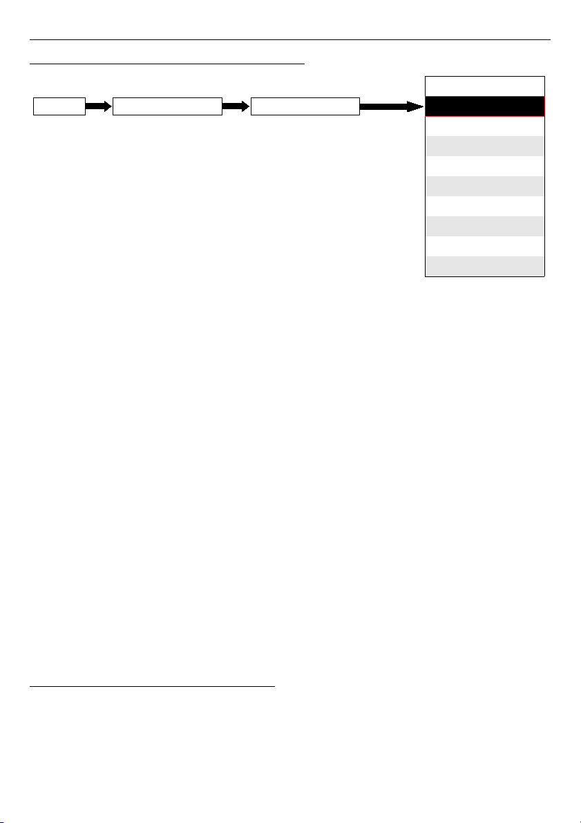
User Manual For - CONTROLLER/DATA RECORDER MultiCon CMC-99/141
7.8.2. Logical channels - Hardware input mode
This mode allows the user to measure data from installed input modules which can be
displayed, and/or processed in any other logical channels (e.g. by mathematical function or
virtual relay) or it can be the data source for controlling outputs.
The
Logical channels
parameters in
Hardware inpu
t mode are:
–
Name
- it gives the name to the logical channel,
–
Unit
- for
Built-in modules
it will automatically use the default
Unit
, to change the
unit use the
Scaling
parameter in
Processing
parameter block,
–
Mode=Hardware input
- in this parameter user can select the source type of the
data for the logical channel,
–
Source
- in this parameter user selects the source of the data from the hardware
input list for the logical channel (see below in this
Chapter
),
–
Configure source
button - after pressing this button user can change the source
configuration, e.g. the range of the input value (see below in this
Chapter
), another
method to change the source configuration is to use the
Built-in inputs
menu
(see
Chapter 7.9. BUILT-IN INPUTS
),
–
Latch
parameter block - allows user to set the
latch function
which will hold the last
value of a channel (discussed in
Chapter 7.8.1. Logical Channels - General
settings
),
–
Processing
parameter block - is used for scaling and filtering data (discussed in
Chapter 7.8.1. Logical Channels - General settings
),
–
Displaying
parameter block - these parameters allow the user to select the format
and range of the data displayed on the screen (discussed in
Chapter 7.8.1. Logical
Channels - General settings
),
Source
parameter in
Hardware input
mode
After pressing the
Source
button a list of available hardware inputs appears. The selected
option will be the source of the data for this logical channel. A sample list of available
hardware inputs for a device with only one input module
I16
- 16 current inputs
(see
Appendices 8.2. UI4, UI8, UI12, U16, U24, I16, I24 – VOLTAGE and CURRENT
MEASUREMENT MODULES
) is shown in
Fig. 7.42
.
84
disabled
Hardware input
Hardware output monitor
Modbus
Set point value
Math function
Controller
Profile/timer
Profile/timer (cycle counter)
Data from other channel
Mode
Logical channelDevice configurationMENU
Page 85
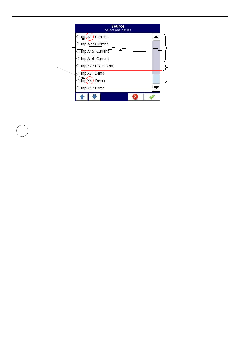
User Manual For - CONTROLLER/DATA RECORDER MultiCon CMC-99/141
see
Fig. 4.8
Fig. 7.42. The view of a sample list of available hardware inputs for a device
In the device there are two methods to change the source configuration of the
Built-in inputs
:
•
using
Configure source
button in
Logical channel
menu in
Hardware
input
mode,
•
using the
Built-in inputs
menu,
The
Source
for
Hardware input
mode can be (in the same order as list in the device - see
Fig. 7.42
):
a) installed
input modules
in the appropriate slots A, B or C (see
Fig. 4.8
) - the list of
currently available modules is on the website,
Description of input modules parameters is shown in
Chapter 7.9.2. Built-in inputs - Input
modules
.
The following steps change the
Source configuration
for the sample of 3 modules shown in
Fig. 7.43
:
– Step
(1)
- selection of
Source
for channel in
Hardware input
mode, for example:
Inp.A1:Current
, next press the
Configure source
button to enter
Source
configuration
menu,
– Step
(2)
- press the
Mode
button to change range of the current input,
– Step
(3)
- choose from the list of available options for signal range - for example:
Current 0-20mA
(for current module),
85
Slot A, Input 1
Slot X (built-in slot)
Input 4
I16 Module
16 current inputs
Built-in binary input
Built-in Demo input
i
Page 86
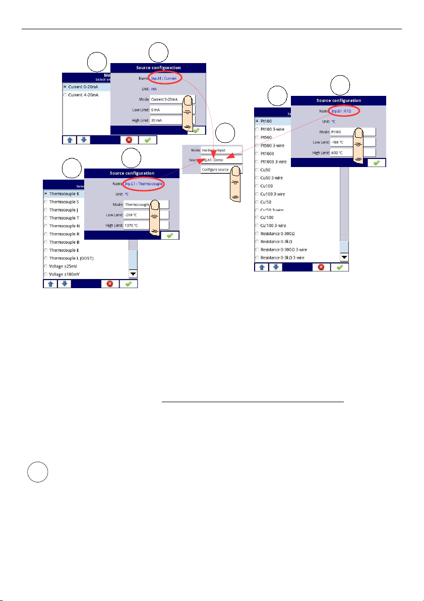
User Manual For - CONTROLLER/DATA RECORDER MultiCon CMC-99/141
Fig. 7.43. Change source configuration for different types of modules
b) built-in digital input is always designated as
Inp.X2: Digital 24V
The device has a built-in digital input, which can be used, for example as a switch for a
process. Descriptions of parameters is shown in
Chapter 7.9.3. Built-in inputs - Binary
input Inp.X2 : Digital 24V
.
c) built-in
Demo
input numbered
Inp.X3:Demo, Inp.X4: Demo, Inp.X5: Demo
The device has 3 built-in simulation
Demo
inputs which can be defined by the user.
Descriptions of parameters is presented in
Chapter 7.9.4. Built-in inputs - Demo input
numbered X3, X4, X5
.
User should remember, that if Hardware input is displayed in more than one logical
channel and if user will change parameters in one of these channels, that will results
the same changes in all the others.
86
1
2
3
3
2
3
2
i
Page 87
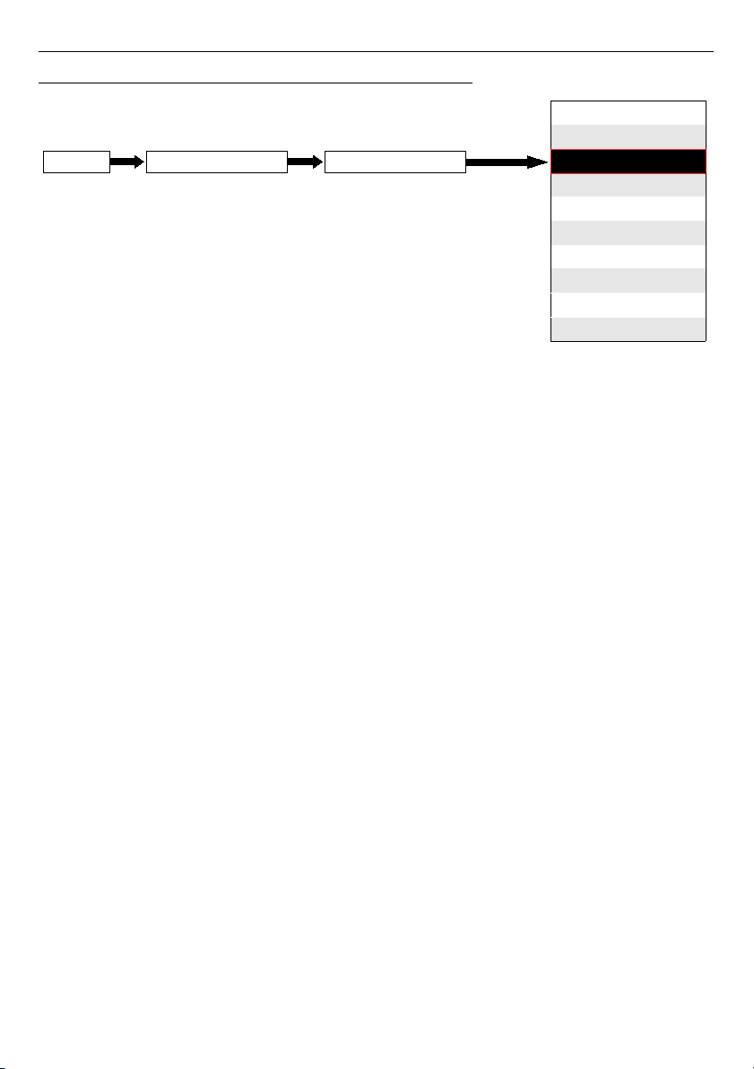
User Manual For - CONTROLLER/DATA RECORDER MultiCon CMC-99/141
7.8.3. Logical Channels - Hardware output monitor mode
This mode allows the user to display data from built-in output modules, processed in any
other logical channels (e.g. by mathematical function or virtual relay) or it can be the data
source for controlling another output.
A view of the configuration of a
Logical channel
in
Hardware output monitor
mode is
shown in
Fig. 7.44
.
The parameters of a
Logical channel
in
Hardware output monitor
mode are:
–
Name
- it gives the name to the logical channel,
–
Unit
- for
Built-in modules
it will automatically default to the unit of the module. To
change the unit use the
Scaling
parameter in
Processing
parameter block,
–
Mode=Hardware output monitor
- in this parameter user selects the source of data
for logical channel,
–
Source
- in this parameter user selects the source of data from the available built-in
outputs list for the logical channel (see below in this
Chapter
),
–
Latch
parameter block - allows the user to set the
latch function
which will hold the
last value of a channel (discussed in
Chapter 7.8.1. Logical Channels - General
settings
),
–
Processing
parameter block - is used for scaling and filtering data (discussed in
Chapter 7.8.1. Logical Channels - General settings
),
–
Displaying
parameter block - these parameters allow the user to select the format
and range of data displayed on the screen (discussed in
Chapter 7.8.1. Logical
Channels - General settings
),
87
disabled
Hardware input
Hardware output monitor
Modbus
Set point value
Math function
Controller
Profile/timer
Profile/timer (cycle counter)
Data from other channel
Logical channelDevice configurationMENU
Mode
Page 88
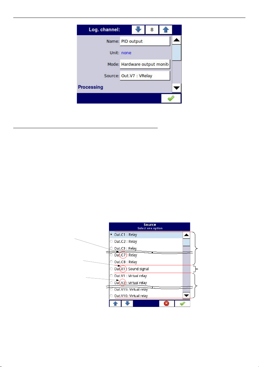
User Manual For - CONTROLLER/DATA RECORDER MultiCon CMC-99/141
Fig. 7.44. Input channels menu – parameters specific for Hardware Output Monitor mode
Source
parameter in the
Hardware output monitor
mode
After pressing
Source
, a list of available hardware outputs appears. The selected option will
be the source of data for that logical channel. An example list of available hardware outputs
for the device with only one output module such as
R81
- 8 relay outputs module
(see
Appendices 8.13. R45, R81, R65, R121 - RELAY MODULES
) is shown in
Fig. 7.45
.
Source
for the
Hardware output monitor
mode can be (in the same order as in the list in
device - see
Fig. 7.45
):
– installed hardware output modules in the respective slots A, B or C (see
Fig. 4.8
)
-a list of modules currently available is on the website; more about the output
modules in
Chapter 7.10. BUILT-IN OUTPUTS
,
– built-in
Sound signal
output is always marked as
Out.X1: Sound signal
- more
about the
Sound
outputs is in
Chapter 7.10. BUILT-IN OUTPUTS
,
– built-in Virtual relays marked as Out. V1 - V16 - more about Virtual relay in Chapter
7.10. BUILT-IN OUTPUTS
.
See
Fig. 4.8
Fig. 7.45. Sample list of available hardware outputs
88
R81 module
8 relay outputs
Built-in
Sound output
Built-in
Virtual relay
Slot X (biuilt-in slot)
Output 1
Slot V (built-in slot)
Output 2
Slot C, Output 7
Page 89
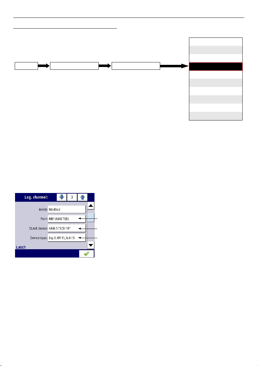
User Manual For - CONTROLLER/DATA RECORDER MultiCon CMC-99/141
7.8.4. Logical Channels - Modbus mode
Modbus
mode allows the user to configure the logical channel to:
– read/write the data from/to a SLAVE device transmitted over RS-485 Modbus RTU
(MultiCon device in
MASTER
mode),
– read/write the data from/to logical channel of MultiCon device transmitted over RS-
485 Modbus RTU (MultiCon device in SLAVE mode) or by Ethernet port (Modbus
TCP/IP, MultiCon device in
SLAVE
mode)
This data stored in the logical channel in Modbus mode can be display on screen, processed
by other logical channels (e.g. by mathematical function or virtual relay) or it can be the data
source for controlling an output.
Fig. 7.46. Sample Logical channel setting in Modbus mode
The parameters of
Logical channel
in
Modbus
mode are (see
Fig. 7.46
):
–
Name
- it gives the name to the logical channel,
–
Unit
- to create a unit use the
Scaling
parameter in
Processing
parameter block
(more information see
Chapter 7.8.1. Logical Channels - General settings
),
–
Mode=Modbus
- in this parameter the user selects source type of data for logical
channel,
–
Port
- this parameter allows the user to select a serial/ethernet port from the list. The
basic version of MultiCon has one built-in RS-485 port. The number of serial ports
can be increased by installing a communication module into slot D of the device.
This module offers 2 additional serial ports (one RS-485, and one RS-485/RS-232)
89
Port MB1, Multicon in MASTER mode for this port
Modbus address: '1', Device name: "SCK-10"
Input channel number: '1', HOLDING Register: '1h', size: 'b.0-15':
disabled
Hardware input
Hardware output monitor
Modbus
Set point value
Math function
Controller
Profile/timer
Profile/timer (cycle counter)
Date from other channel
Mode
Logical channelDevice configurationMENU
Page 90
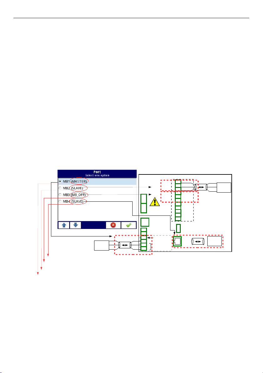
User Manual For - CONTROLLER/DATA RECORDER MultiCon CMC-99/141
and one ethernet port, which allows for an advanced Multi-Modbus system
(see
Fig. 7.47
).
–
Slave device
- this parameter is only visible if the selected option in the
Port
parameter is in
Modbus MASTER
mode (see
Chapter 7.15.3. Modbus - MASTER
mode
). Using this parameter the user can select the SLAVE device from the list
defined in the
Modbus
menu to exchange the data with it,
–
Device input
- this parameter depend on the mode of the port
• for
Modbus MASTER
mode (see
Chapter 7.15.3
), using this parameter the
user can select the read register of the SLAVE device from the list defined in the
Modbus
menu,
• for
Modbus SLAVE
mode (see
Chapter 7.15.2
), next to
Device input
label is
the logical channel number and register number assigned to this logical channel
are displayed,
–
Latch
parameter block - allows user to set the
latch function
which will hold the last
value of a channel (discussed in
Chapter 7.8.1. Logical Channels - General
settings
),
–
Processing
parameter block - is used for scaling and filtering data (discussed in
Chapter 7.8.1. Logical Channels - General settings
),
–
Displaying
parameter block - these parameters allow the user to select the format
and range of data displayed on the screen (discussed in
Chapter 7.8.1. Logical
Channels - General settings
),
Fig. 7.47. Sample list of available Modbus ports
90
Power supply
(depending on version)
1
2
8
5
6
7
3
4
SERV ICE
+24V DC ± 5%
(Imax. = 200mA)
digital input
0/15..2 4V DC
RS-485
GND
GND
A+
B-
isolated
19
16
17
18
14
15
RJ-45
ETH
USB
host
RS-485 (2)
GND
RxD
A+
B-
13
10
11
12
9
A+
B-
GND
TxD
CTS
RTS
RS-2 32 + RS-48 5 (3)
GND
19
GND
A+
B-
GND
A+
Slot D- ACM module
Port MB1
Port MB2
Port MB3
B-
Multicon is MASTER device for this network
Multicon is SLAVE device for this network
Multicon is disabled for this network
Port MB4
Multicon is SLAVE device for this network
MASTER
device
SLAVE
device
MASTER/
SLAVE
device
MASTER/
SLAVE
device
Page 91
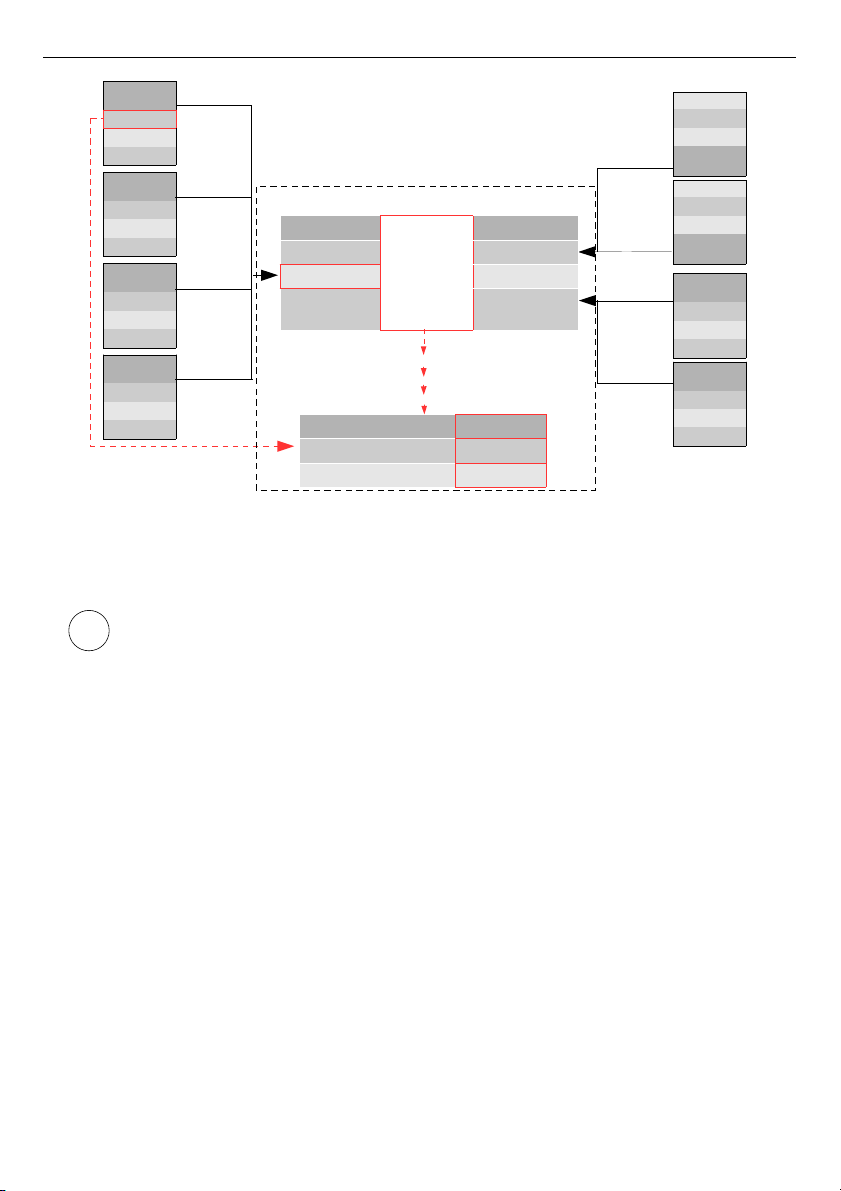
User Manual For - CONTROLLER/DATA RECORDER MultiCon CMC-99/141
Fig. 7.48. An example of configuration block diagram of the Modbus protocol implemented in
the device
Logical channel's in Modbus mode reading registers from Slave devices that
are not connected, will returns an error and instead of the value will display the
state
-ERR-
.
For more information about the Modbus protocol implemented in the MultiCon see
Chapter
7.15. MODBUS
.
91
i
Port MB1
SLAVE Device Address 1
Device input
Register 0
SLAVE
Device
Reg. 0
...
Reg. N
SLAVE
Device
Reg. 0
...
Reg. N
SLAVE
Device
Reg. 0
...
Reg. N
SLAVE
Device
Reg. 0
...
Reg. N
Address 1
Address 2
Address 52
Address 82
SLAVE
Device
Reg. 0
...
Reg. N
SLAVE
Device
Reg. 0
...
Reg. N
Reg. N
...
Reg. 0
SLAVE
Device
Address 82
Address 8
Reg. N
...
Reg. 0
SLAVE
Device
Address 1
Address 4
Built-in
Modbus
Master
Advanced
Port MB2
Port MB1
Port MB3
Unit
Device c onfigurati on
Hardware I nputs
Modbus
Page 92
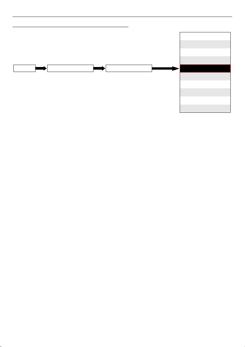
User Manual For - CONTROLLER/DATA RECORDER MultiCon CMC-99/141
7.8.5. Logical Channels - Set point value mode
In
Set point value
mode the user defines constant value which can be displayed on the
screen, used for calculations in other channels (e.g. in math functions, controllers etc.) or as a
data source for built-in or external outputs which will control any object.
The parameters of the
Logical channels
in
Set point value
mode should be:
–
Name
- it gives the name to the logical channel,
–
Mode=Set point value
- in this parameter user selects source type of data for logical
channel,
–
Unit
- this parameter allows the user to define any unit,
–
Set point value
- this parameter is visible only if
Edit button=disabled
, after
pressing the button next to
Set point value
parameter appears in window allowing
entry of a value (see
Fig. 7.6
), this value will be a source of data for this Logical
channel.
–
Edit button
- this parameter allows you to activate the button in the panel data
(see
Fig. 7.49
), this parameter has two options:
•
disabled
- the button is disabled on the display, in this case the data source of
logical channel will be the value set in the
Set point value
parameter,
(see
Fig. 7.50
),
•
enabled
- this button is active, in this case the data source of logical channel will
be the value set after pressing the button, but the initial value is the number
written in
Set point value
parameter, before setting the
Edit button
parameter
to
enabled
,
–
Button mode
– parameter is visible only in case when
Edit button
parameter is set
on
enabled
, and
Format
parameter in
Displaying
parameter block is set on
binary
,
it has two options:
•
bistable
– pressing and releasing the button will cause permanent change of
state,
•
monostable
- pressing and releasing the button will cause that the button on
0,1 second will switch from
OFF
state to ON state, and after that time, it will
switch again to
OFF
state,
92
disabled
Hardware input
Hardware output monitor
Modbus
Set point value
Math function
Controller
Profile/timer
Profile/timer (cycle counter)
Data from other channel
Mode
Logical channelDevice configurationMENU
Page 93
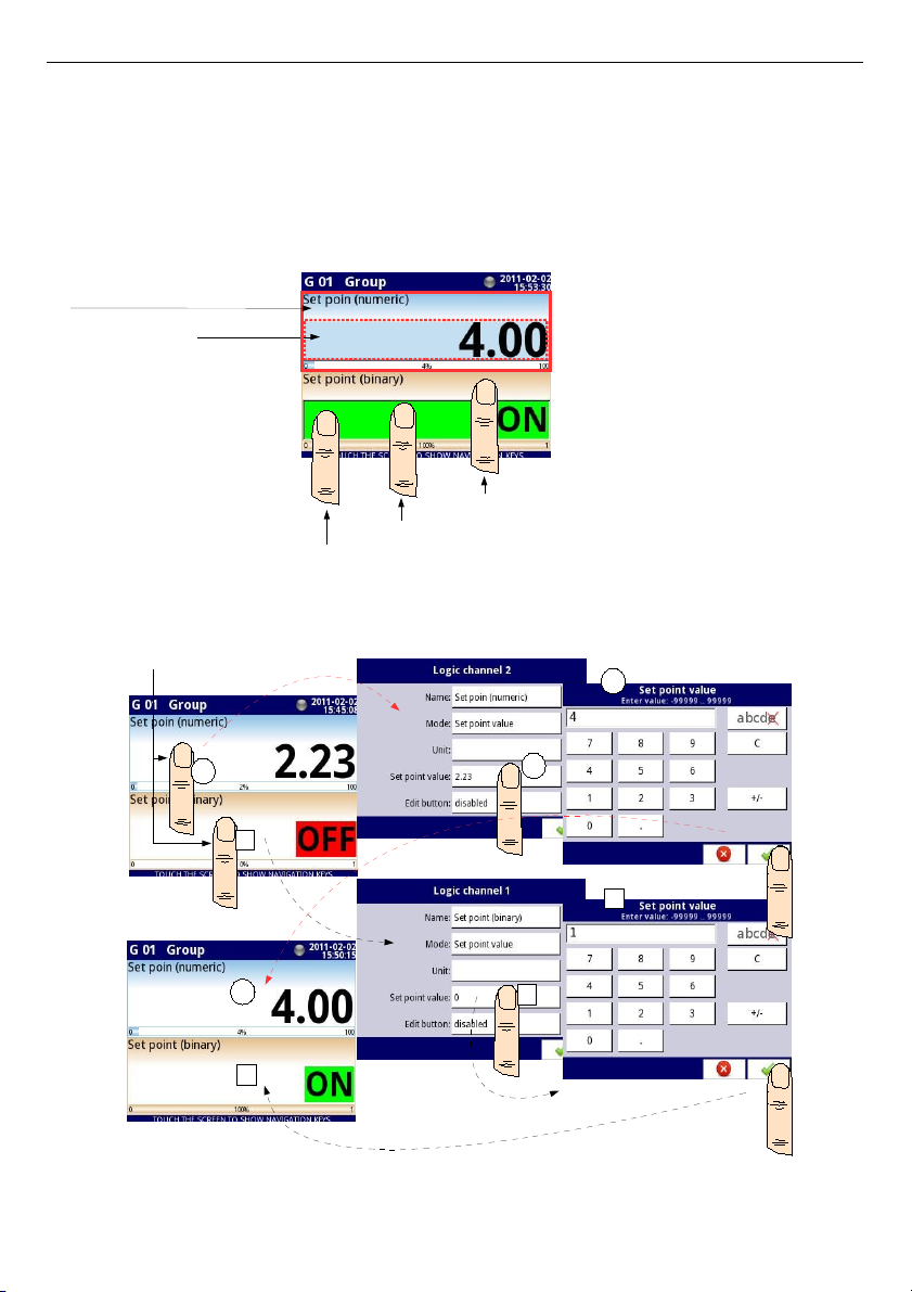
User Manual For - CONTROLLER/DATA RECORDER MultiCon CMC-99/141
–
Latch
parameter block - allows user to set the
latch function
which will hold the last
value of a channel (discussed in
Chapter 7.8.1. Logical Channels - General
settings
),
–
Displaying
parameter block - for these parameters the user select format and range
of data to be displayed on the screen (discussed in
Chapter 7.8.1. Logical
Channels - General settings
),
Fig. 7.49. Data panels for Logical channel in Set point value mode
Fig. 7.50. Configuration of the value for Logical channel in Set point value for the disabled
button
93
Button area
Area of data panel for Logical channel
Touch button to edit or change the value of logical channel
Touch & hold 2-3 sec. data panel to inside into logical channel configuration
Touch & hold 2-3 sec. button to inside into logical channel configuration
4
1
2
3
1
2
3
4
Touch & hold 2-3 sec.
Page 94
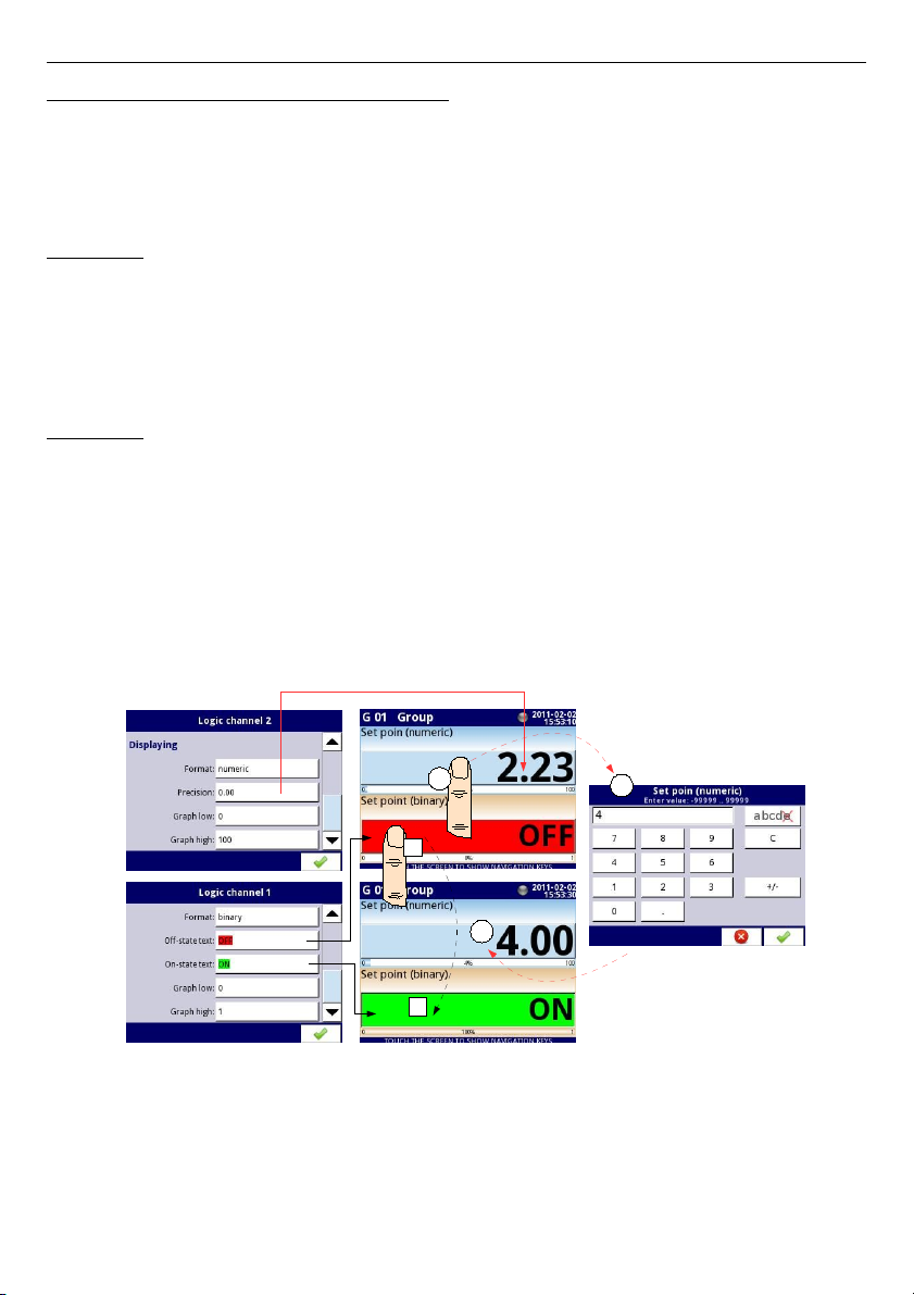
User Manual For - CONTROLLER/DATA RECORDER MultiCon CMC-99/141
Manual operation of a button in the data panel
Action button in the data panel depends on the parameters from
Latch
block (description of
the
Latch
parameter block in Chapter
7.8.1. Logical Channels - General settings
) and on
the
Format
parameter in the
Displaying
parameter block (description of the
Displaying
parameter block in Chapter
7.8.1. Logical Channels - General settings
).
a)
for disabled latch function
, see
Fig. 7.51
For format:
–
numeric
and
time
– after pressing the button an edit window appears allowing entry
of value (see
Fig. 7.6
), this value will be a source of data for that Logical channel,
–
binary
- pressing the button causes a switch between the states (
'0'
and
'1'
) display
in the data panel in accordance with the text states set in the parameters:
Off-state
text
(channel value =
'0'
) and
On-state text
(channel value =
'1'
) in the
Displaying
parameter block,
b) for enabled latch function
For format:
–
numeric
and
time
– after pressing the button an edit window appears allowing entry
of value (see
Fig. 7.6
), which enters the new value that isn’t a data source for this
channel but the value stored at the time of activation of the latch function, in the edit
window the value of the button still appears a new value which will be the data
source for that logical channel by disabling the latch function,
–
binary
- pressing the button does not switch between the states (
'0'
and
'1'
)
displayed in the data panel in accordance with the text states set in the parameters:
Off-state text
(channel value =
'0'
) and
On-state text
(channel value =
'1'
) in the
Displaying
parameter block, but with each new press of the button the state of
button is stored in the buffer and set the value of logical channel with the currently
stored state when the latch function is disabled again.
Fig. 7.51. Manual operation of the button for numeric and binary format
94
2
3
1
1
2
Page 95
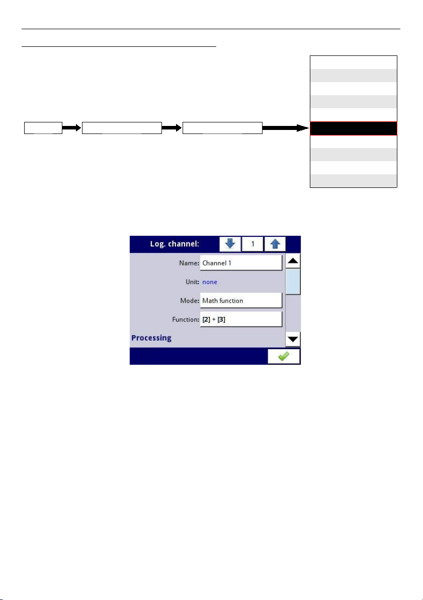
User Manual For - CONTROLLER/DATA RECORDER MultiCon CMC-99/141
7.8.6. Logical Channels - Math function mode
This mode allows the user to define the Math function for display on the screen,
processed this data in any other logical channels or it can be the data source for output to the
control and settings of any object.
Fig. 7.52. Input channels menu - parameters specific for Math function mode
MultiCon
has a wide variety mathematical function which increases functionality and the
range of the applications of the device.
Fig. 7.52
presents parameters of
Input channel
into
Math function
mode. This mode allows the user to display channel value, process this data
in any other logical channel or it can be the data source for an output to control and set any
object.
The parameters of
Logical channel
in
Math function
mode are:
–
Name
- it gives the name to the logical channel,
–
Unit
- to create a unit use the
Scaling
parameter (more information see
Chapter
7.8.1. Logical Channels - General settings
),
–
Mode=Math function
– in this parameter user selects source type of data for logical
channel,
–
Function
- this parameter allow user to select math function from the list, for more
information see below in this
Chapter
,
–
Latch
parameter block - allows user to set the
latch function
which will hold the last
value of a channel (discussed in
Chapter 7.8.1. Logical Channels - General
settings
),
95
disabled
Hardware input
Hardware output monitor
Modbus
Set point value
Math function
Controller
Profile/timer
Profile/timer (cycle counter)
Data from other channel
Mode
Logical channelDevice configurationMENU
Page 96

User Manual For - CONTROLLER/DATA RECORDER MultiCon CMC-99/141
–
Processing
parameter block - is used for scaling and filtering of data (discussed in
Chapter 7.8.1. Logical Channels - General settings
),
–
Displaying
parameter block - for these parameters the user select the format and
range of data displayed on the screen (discussed in Chapter
7.8.1. Logical
Channels - General settings
),
Function
parameter in the
Math function
mode
Basic math functions implemented into device are: addition, subtraction, multiplication and
division. The unit allows the operation of logic functions, trigonometric, array operations,
determining the arithmetic mean, finding maximum and minimum values, and many other
function that are discussed in the table below. After pressing the button next to the
Function
label go to a math function menu. This menu consists of the following parameters (Note! Not
all parameters are available for each function):
–
Function
– available for all math functions, by pressing the button next to the this
label a list of available math functions appears, from which the user can select the
appropriate function,
–
Type of source X
– available for certain math functions. Available types are:
•
channel
– means that the
'X'
source will be a logical channel selected from a
list in
Source X
parameter,
•
value
– means that the
'X'
source will be a constant value entered in the
Source X
parameter,
–
Source X
– available for certain math functions. Depends of
Type of source X
parameter. This parameter allows user to:
• select logical channel from list (
Type of source Y=channel
),
• or enter set point value (
Type of source Y=value
),
–
X error handling
– available for some math functions, depending on this parameter,
the user can set following options:
•
errors forwarded to result
– when the result of the selected channel
(
Source X
) is a state: Error, Hi, Lo, or undefined then the output received states:
Err, Hi
or Lo,
•
skip erroneous channels
- means, that these channels, which result in a status
of
Error, Hi, Lo
are ignored in the calculation of selected math function,
–
Init. value mode
– available for some math functions, depending on this parameter,
the user can set following options:
•
channel
– means that initial value will be loaded from selected logical channel,
•
value
– means that initial value will be a constant value entered in the
Initial value
parameter,
–
Init. value source
– available for certain math functions, selects logical channel from
list which will be initial value source for the function,
–
Initial value
– available for certain math functions, constant value which will be initial
value for the function after its reset or device start,
–
Max. value mode
– available for some math functions, depending on this parameter,
the user can set following options:
•
channel
– means that maximal value will be determined by selected logical
channel,
•
value
– means that maximal value will be a constant value entered in the
Maximal value
parameter,
–
Max. value source
– available for certain math functions, selects logical channel
from list which will be maximal value source for the function,
96
Page 97

User Manual For - CONTROLLER/DATA RECORDER MultiCon CMC-99/141
–
Maximal value
– available for certain math functions, constant value which will be
maximal value for the function,
–
Averaging time
– available for
Function=avarege of X
, determines logical channel
amount of samples which fits in this time and will be averaged; after this time
function enters a saturated state,
–
Reset now
– button available for certain math functions, asynchronously resets
function value,
–
Reset mode
– available for some math functions, depending on this parameter, the
user can set following options:
•
disabled
– means that function after reaching maximal value, will stop on this
value,
•
automatic
– means that function after reaching maximal value will axiomatically
resets it self and returns to initial value,
•
from log. channel
– means that function reset is triggered from selected logical
channel,
–
Reset source
– available for some math functions, selects a logical channel which
will be reset source for the function,
–
Reset triggering
– available for some math functions, allows to select triggering
method from the logical channel, the user can set following options:
•
high level
– function resets when resetting channel is in high state,
•
low level
– function resets when resetting channel is in low state,
•
rising edge
– function resets when in resetting channel rising edge occurs,
•
falling edge
– function resets when in resetting channel falling edge occurs,
–
J input mode
– available for
Function=flip flop
, the user can set following options:
•
always 0
– flip flop J input is always in logical state '0',
•
always 1
– flip flop J input is always in logical state '1',
•
from log. channel
– means that flip-flop J input source will be logical state
value of selected logical channel,
•
from channel (negation)
– means that flip-flop J input source will be negated
logical state value of selected logical channel,
–
J input source
– available for
Function=flip flop
, selects a logical channel which
will be source for flip-flop J input,
–
K input mode
– available for
Function=flip flop
, the user can set following options:
•
always 0
– flip flop K input is always in logical state '0',
•
always 1
– flip flop K input is always in logical state '1',
•
from log. channel
– means that flip-flop K input source will be logical state
value of selected logical channel,
•
from channel (negation)
– means that flip-flop K input source will be negated
logical state value of selected logical channel,
–
K input source
– available for
Function=flip flop
, selects a logical channel which
will be source for flip-flop K input,
–
Clock source
– available for
Function=flip flop
but unavailable if parameters
J input mode
and
K input mode
are both set as always 0, allows to select a logical
channel which will be flip-flop clock input source,
–
Clock triggering
– available for
Function=flip flop
, the user can set following
options:
•
high level
– flip-flop triggers when in selected in
Clock source
parameter
channel is in high logical state,
•
low level
– flip-flop triggers when in selected in
Clock source
parameter
channel is in low logical state,
97
Page 98

User Manual For - CONTROLLER/DATA RECORDER MultiCon CMC-99/141
•
rising edge
– flip-flop triggers when in selected in
Clock source
parameter
channel rising edge occurs,
•
falling edge
– flip-flop triggers when in selected in
Clock source
parameter
channel falling edge occurs,
–
R input mode
– available for
Function=flip flop
, the user can set following options:
•
disabled
– resetting flip-flop R input in inactive,
•
from log. channel
– means that flip-flop R input source will be logical state of
the selected logical channel,
•
from channel (negation)
– means that flip-flop R input source will be negated
logical state of the selected logical channel,
–
R input source
– available for
Function=flip flop
, selects a logical channel which
will be flip-flop R input source,
–
S input mode
– available for
Function=flip flop
, the user can set following options:
•
disabled
– setting flip-flop S input in inactive,
•
from log. channel
– means that flip-flop S input source will be logical state of
the selected logical channel,
•
from channel (negation)
– means that flip-flop S input source will be negated
logical state of the selected logical channel,
–
S input source
– available for
Function=flip flop
, selects a logical channel which
will be flip-flop S input source,
–
Type of source Y
- available for certain math functions. Available types are:
•
channel
- meaning that the
'Y'
source will be a logical channel selected from a
list in
Source Y
parameter,
•
value
- means that the
'Y'
source will be a constant value entered in the
Source Y
parameter,
–
Source Y
- available for certain math functions. Depends of
Type of source Y
parameter. This parameter allows user to:
• select logical channel from list (
Type of source Y=channel
),
• or enter set point value (
Type of source Y=value
),
–
Unit
- available for certain trigonometric functions. Allow an option to be selected:
• degree
• radian
Example of configuration of logical channel in Math function mode
Steps to configure the function which summarizing values of logical channels: 1, 3, 4, 5 are
shown in
Fig. 7.53
. If any logical channel has
Error
state or value exceeds the range of a
logical channel (Hi, Lo) then output has the same state. The following steps are:
(1)
- Select
Math function
mode in the appropriate logical channel (e.g. 14). Press
the button next to the
Function
label to enter the
Function
menu,
(2)
- Enter the
Function
sub-menu by pressing the button next to the
Function
label,
(3)
- Choose function from the list, in this case:
Sum X[i]
,
(4)
- Press button next to the Source X label to enter to the channel list,
(5)
- Choose logical channel from a list, in this case 1, 3, 4, 5,
(6)
- Set the
X error handling
parameter to
errors forwarded to result
,
(7)
- After configuring, we get a description of function next to the
Function
label:
Sum [1, 3, 4, 5]
,
98
Page 99
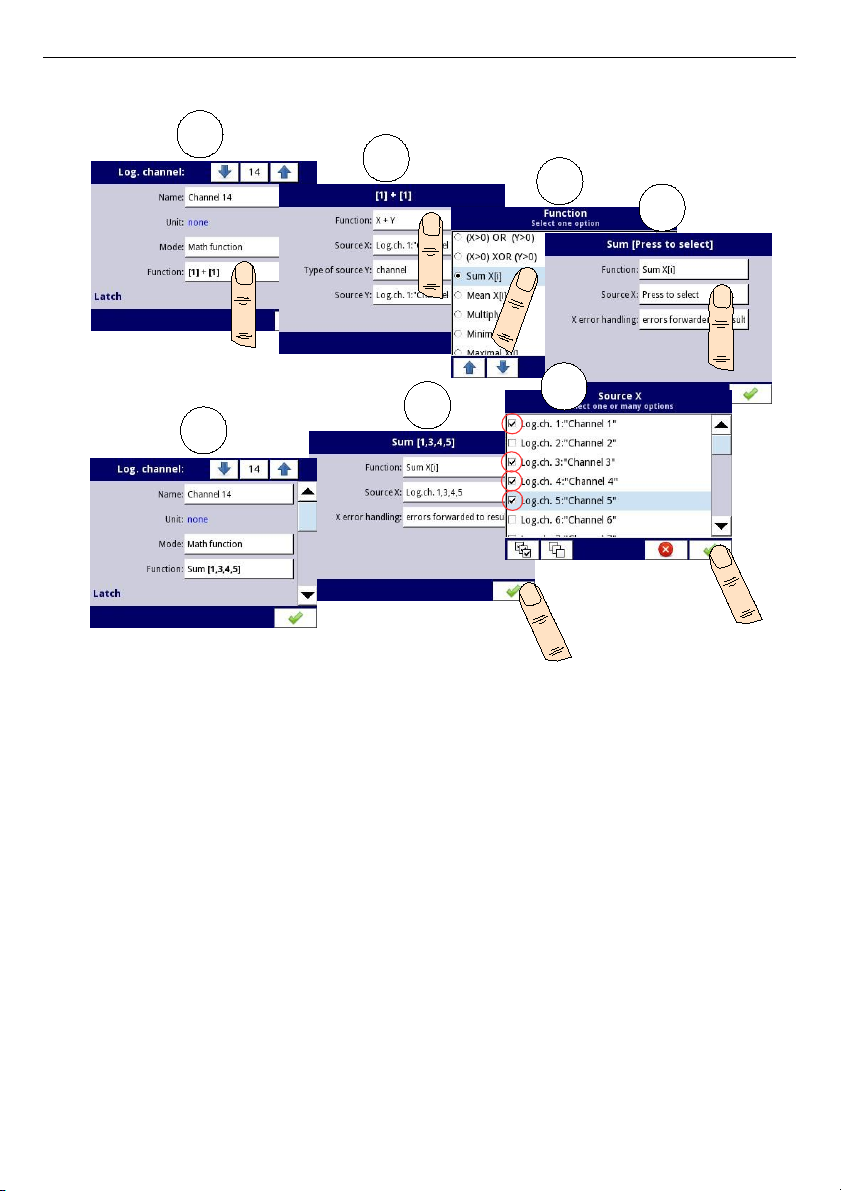
User Manual For - CONTROLLER/DATA RECORDER MultiCon CMC-99/141
Fig. 7.53.
Sample configuration of logical channel in
Math function
mode
99
1
2
3
4
5
6
7
Page 100
User Manual For - CONTROLLER/DATA RECORDER MultiCon CMC-99/141
Math function Description Example
X+Y
The sum of
Source X
and
Source Y
value
[1] + [2]
– The sum of
channel 1 and 2
X-Y
The subtraction of
Source X
and
Source Y
value
[1] - [2]
– The subtraction of
channel 1 and 2
X/Y
The ratio of
Source X
and
Source Y
value
[1] / [2]
– The ratio of the
channel 1 to channel 2
X*Y
The product of
Source X
and
Source Y
value
[1] * [2]
– The product of
channel 1 and channel 2
(X>0) AND (Y>0)
Logical AND
[1] AND [2]
- result = 1, when
the value of channel 1 and 2
is greater than 0
(X>0) OR (Y>0)
Logical OR
[1] OR [2]
– result = 1, when
the value of channel 1 or/and
2 is greater than 0
(X>0) XOR (Y>0)
Logical XOR
[1] XOR [2]
– result = 1,
when the value of the one
channel is greater than 0 and
the value of second channel
is
≤ 0.
When both channels
have values
≤ 0
or when both
channels have values >0
then the result is 0.
SUM X[i]
The sum of selected channels
SUM[1,2,3,4]
– the result is
the sum of channels 1, 2, 3, 4
MEAN X[i]
The mean value of the selected
channels.
MEAN[1,2,3,4]
– the result is
the arithmetic mean value of
channels 1, 2, 3, 4
MULT X[i]
The product of the value of the
selected channels.
MULT[1,2,3,4]
- the result is
the product of channels 1, 2,
3, 4
MIN X[i]
The smallest value of selected value
of the selected channels
MIN[1,2,3,4]
- the result is
lowest value of the selected
channels 1, 2, 3, 4
MAX X[i]
The largest value of selected value
of the selected channels
MAX[1,2,3,4]
- the result is
highest value of the selected
channels 1, 2, 3, 4
100
 Loading...